1
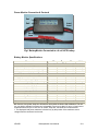
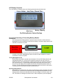
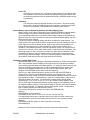
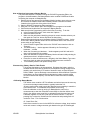
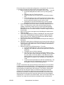
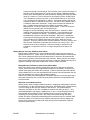
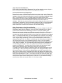
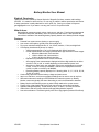
Battery Monitor User Manual
Rights & Permission
This document was created by Wayne Getchell of Sagacitic Solutions, amateur radio callsign
VE3CZO. It is meant for reference use. Do not copy or publish it without permission and citation.
If asked, permission is easily obtained for not for profit use. Send your request to Wayne at
[email protected]. If you want to use any part or all of it for profit let’s talk.
What it does:
BatteryMonitor measures supply voltage, load current, and time. From these measurements
it calculates load power and battery use in amp hours and watt hours. It also provides the
user with an estimate of the remaining battery capacity based on the battery terminal voltage.
Features:
·
·
·
·
·
·
·
·
·
·
·
·
Powered from system source (battery or power supply).
Low current consumption, typically 2mA with backlight off.
Four menu selected backlight levels, off, low, 0.5mA; medium, 1.5mA; and high 2mA.
LCD Display simultaneously shows six values.
o Voltage measurement 4.5 to 24.6V displayed with 100mV resolution.
o Current measurement auto ranged provides three digit resolution in three ranges:
§ 000mA to 999mA with 1mA resolution
§ 1.00A to 9.96A with 10mA resolution
§ 10.0A to 40.9A with 100mA resolution
o Elapsed time to 99h59min with 1minute resolution.
o Auto-ranging Power measurement displayed with three digit resolution as either
xxxmW, x.xxW, xx.xW, or xxxxW depending on the measured power level.
o Amp hours or Watt hours user selectable. Amp hours are displayed as xxxmAh,
x.xxAh, xx.xAh or xxxxAh up to 9999Ah. Watt hours is displayed as xxxmWh,
x.xxWh, xx.xWh or xxxxWh up to 9999Wh.
o Remaining Battery capacity displayed in % showing either 0, 2, 5, 10, 20, 50, 60,
70, 80, 90, or 99%.
Continuously captures minimum battery voltage and peak current.
Amp hour, Watt hour, and time accumulated readings can be reset to zero at any time.
Hibernate mode saves readings to EEPROM and is restored on power-up. Battery
Monitor consumes typically 2uA when hibernating so can be left attached to batteries.
Battery Monitor automatically powers up when initially attached to a power source.
Flexible 15cm 12ga pigtails with Power Pole connectors on source and load leads.
Updates readings frequently, 10,000 times per hour, or about 2.75 times per second.
Utilities Menu and two function switches manage BatteryMonitor features.
Low series resistance 7.5mOhms typically with 15cm 12ga pigtails (Rsense=2.5mOhms).
VE3CZ0
BatteryMonitor User Manual
1/11
Power Monitor Connection & Controls
Sw1
Load
Lead
Sw2
Source
Lead
Fig.1 BatteryMonitor Connected to a 4 cell LIPO battery
Battery Monitor Specifications
Parameter
Min
Typ
Max
Units
Supply Voltage
5.0
25
Volts
Continuous Load Current
30
Amps
Maximum Peak Load Current (<1min)
40
Amps
Supply Current (display backlight off)
2.0
2.5
mA
Supply Current (display backlight hi)
4.0
5.0
mA
Supply Current in Hibernate or Off states
2
4
uA
Source Voltage Display
24.6
Volts
Load Current Display (w/o Sf correction)
0.000
40.9
Amps
1
Load Power Display
0.00
>1,000
Watts
Amp Hour Display
0.000
9,999
Ah
Watt Hour Display
0.000
9,999
Wh
Time Display
00:00
99:59
Hrs:min
Voltage Accuracy
1
2
%
Current Accuracy
1
2
%
Time Accuracy
2
%
Power, Amp hour, or Watt hour Accuracy
2
5
%
NB: Current, time, power, Amp hour & Watt hour accuracies are shown after calibration. The unit
can run without calibration but accuracy is degraded. Expect up to about 6% error on load current
measurements and up to 8-10% error on Power, Amp hour, and Watt hour measurements.
1. The displayed load power maximum is limited only by the product of the maximum source
voltage times the maximum load current.
VE3CZ0
BatteryMonitor User Manual
2/11
LCD Display Overview
The 16 character LCD display shows the following measurements simultaneously.
Source Voltage
Load Current
Load Power Elapsed Time
Amp Hours or
Watt Hours
Remaining
Battery Capacity
Fig.2 BatteryMonitor Display Readings
Connecting Operating & Controlling Battery Monitor
Connections
For most applications BatteryMonitor is placed in series between a source and load.
BatteryMonitor’s source leads are connected to a battery or a power supply and the load
leads are connected to any load.
Source (5.0-25V) +
Battery Monitor
Load
Connect the Power Pole connector closest to the switches to the source, and the other
connector to the load. BatteryMonitor does not require a load to operate but must be
connected to a source for power.
Turning BatteryMonitor On
When initially connected to a power source between 5.0V and 25V Battery Monitor will
automatically power up. If the source is ramped up slowly the unit may not turn on.
Additionally if the unit is left attached to a battery and turned off or placed in hibernation,
the unit will remain off. In these cases pushing Sw2 momentarily will turn the unit on.
On power-up the display shows a splash screen that indicates the software version on
line one. On line two Source and Load are displayed at each end of the line and arrows
in between point in the direction that the current must flow.
Operating BatteryMonitor
BatteryMonitor is unidirectional. For proper measurements current must always flow from
source to load. If the source and load connectors are swapped BatteryMonitor won’t be
damaged and will show the load rather than the source voltage, but current, power, amp
hour, and watt hour readings will remain at zero. After initial power-up the unit displays
VE3CZ0
BatteryMonitor User Manual
3/11
the splash screen then it’s is coming out from hibernation another display which notifies
the user that the unit is ‘Resuming From Hibernation’ is shown for about four seconds.
The unit then begins measuring and will continue to measure until one of the push
buttons is pushed. BatteryMonitor displays six values simultaneously as shown in figure
two; source voltage, load current, load power, either Amp hours or Watt hours, session
time, and remaining battery capacity. The source voltage is displayed using 4 characters
with a resolution of 0.1volts in the format xx.xV. If the source voltage is under 10.0 volts
the display will show a leading zero. The load current is displayed using 5 characters.
The format depends on the parameter’s value. If it’s under one amp the display is shown
in milliamps and takes the form xxxmA. Between one and 9.99 amps the display is
shown as with a resolution of 10ma as x.xxA, and at ten amps and above the display has
a 100mA resolution and is displayed as xx.xA.
The load power is the product of the source voltage and load current and like the load
current the display varies depending on the value of the load power. This parameter uses
five characters. At low power levels the display has a 10mW resolution and is shown as
x.xxW. If the power increases above 10 watts the display changes to show a 100mW
resolution and displays as xx.xW. When the power increases above 100 watts the
displayed readout resolution changes to one watt and is displayed as xxxW. Note that this
display uses only four of the available five display characters so the leading zero is
blanked. In rare cases at high source voltages and load currents the power can exceed
1,000 Watts in which case the display shows xxxxW.
The battery use can be displayed as either charge in Amp hours or energy in Watt hours.
The user chooses which to display at any time using the utilities menu ‘Choose Ah or Wh’
menu item. Both parameters are accumulated by taking 10,000 readings per hour. Amp
hours accumulates the load current used over time while watt hours multiplies the load
current by the source voltage over the 10,000 readings per hour. Both parameters are
cleared at power-up unless the unit is returning from hibernation. Each parameter then
starts at 0 and occupies six digits on the display. Initial accumulated values are shown in
mAh or mWh from 0 to 999. The display changes resolution over 1000 to 10mAh or
10mWh and is displayed as x.xxAh or x.xxWh up to 9.99. Above 10Ah or 10Wh the
display resolution changes to 0.1Ah or Wh and displays as xx.xAh or Wh up to 99.9.
Above 100 the resolution becomes 1Ah or Wh and the display shows xxxAh or Wh up to
999. Above 1000 Ah or Wh the resolution remains 1Ah or Wh. The maximum value
displayed is 9,999 Ah or Wh. At 10,000 the display rolls over and starts again at zero.
The elapsed time portion of the display keeps track of the time in hours and minutes up to
99hours and 59 minutes. At 100 hours the elapsed time rolls over and starts again from
zero. The user can reset the time to zero at any time along with the Amp hour and Watt
hour readings by using the ‘Restart Readings’ item in the utilities menu.
The remaining battery capacity reading provides the user with an estimate of the
percentage battery capacity remaining. Additional information about this parameter and
how it’s derived is available in the ‘Percent Battery Capacity Remaining Readings and
Stored Battery Data’ section of this document.
Additional features can be accessed through the utilities menu and these functions are
detailed in the ‘Utilities Menu’ section of this document.
Sw1 and Sw2 Operation While Measuring
Pressing Sw1 for less than two seconds will invoke the Utilities menu. If Sw1 is held
down for more than two seconds the unit will go into ‘Hibernate’ mode.
Pressing Sw2 momentarily will turn the unit on if it is off and connected to a source. When
BatteryMonitor is on, pressing Sw2 for more than two seconds turns the unit off.
If BatteryMonitor had returned from Hibernate mode at the beginning of the session and if
the ‘Clear Readings’ menu was never invoked then when Sw2 is pushed the unit will
update stored parameters to EEPROM and enter Hibernate mode rather than turn off.
If Battery Monitor resumed from hibernation and is unplugged from the source without first
going back into hibernation or being turned off, the current session data will be lost, but
VE3CZ0
BatteryMonitor User Manual
4/11
the hibernation data from the last session is still available and will be restored on next
power-up.
Hibernation Mode
BatteryMonitor can be put to sleep by pressing Sw1 for more than two seconds. This
mode is useful for example if you have completed a session with a battery, partially
discharged it, and want to resume use at a later time. On entering Hibernation,
BatteryMonitor stores the elapsed time, Amp hours, Watt hours, minimum source voltage,
and peak load current in EEPROM then powers down. When hibernating while connected
to a source BatteryMonitor consumes about two micro amps. This is typically less than
the self discharge current of most batteries. So BatteryMonitor can be stored by
disconnecting it or it can be left attached to the battery. At the start of the next session,
BatteryMonitor will automatically power up when it is reconnected to a battery. If it was
left connected to the battery, pushing Sw2 momentarily restores power. On power up
BatteryMonitor displays an information screen after the splash screen for about four
seconds that indicates it’s ‘Resuming from Hibernation’. On returning from Hibernation
BatteryMonitor restores the elapsed time, Amp hour, Watt hour, minimum source voltage,
and peak load current readings form the last session. BatteryMonitor then starts
measuring and continues to accumulate data. For further information on Hibernation
behaviour refer to the ‘Sw1 and Sw2 Operation While Measuring’ section.
Additional Applications
BatteryMonitor can also be used to monitor a battery under charge by connecting source
leads to the battery charger and load leads to the battery being charged.
Battery
Charger
Battery Monitor
- Battery
+ (5.0-25V)
Utilities Menu
Battery Monitor contains the following utility menu items
· Show Vmin & ILp – shows minimum voltage and maximum peak current.
These two readings can also be cleared using this menu item
· Clear Readings – clears Amp hour, Watt hour, time, minimum voltage and
peak current readings
· Choose Ah or Wh – selects units displayed mode either Amp hours or Watt
hours
· Set Backlight – selects High, Medium, Low, or Off backlight levels
· Select Battery – choose one of up to 8 batteries governing percent capacity
readings
· Hibernate – places BatteryMonitor into its hibernation state
· Power Off – turns BatteryMonitor off
· Calibrate – Calibrate the current to voltage converter Scaling Factor, SF and
Time-Tick cal to improve measurement accuracy.
Enter the utilities menu items by pushing Sw1 for less than two seconds. Scroll through
the utilities menus by momentarily pressing Sw1. When at the end of the utilities menu
items pressing Sw1 again returns the user to the top of the menu list.
When a down arrow appears next to Sw1 the user can scroll through sub-menu items, or
change values but they will not be selected or saved. If a left arrow appears next to Sw1,
the user can select that option and it will be executed or saved. Sw2 is used only to
VE3CZ0
BatteryMonitor User Manual
5/11
select, save, or execute menu options. When an option is selected it’s saved or executed
and the program returns to measuring.
While in the utilities menu, the Amp hour, Watt hour, elapsed time, Vmin, and ILp, are not
updated.
All Utilities menus and submenus except the two ‘Calibration’ submenus feature a
timeout timer. If there is no pushbutton activity for 20 seconds the unit will exit the
utilities menu or submenu and return to the measuring system.
Note that in some menu items there is no ability to ‘escape’ back to the measuring
subsystem. In those cases either choose an option to end the utilities menu or wait for
the timeout timer to return the unit to the measuring system. If you enter a menu item by
mistake, and want to exit before the timeout timer is invoked, it’s typically best to select
the ‘No’ option or the current value
Show Vmin & ILp
BatteryMonitor continuously captures the source voltage minimum and load
current maximum readings. This menu section shows those readings. The
readings can also be reset by pressing Y, Sw1. Pressing N, Sw2, preserves the
readings and returns the user back to the measuring mode.
Restart Readings
Select Y to clear all readings or N to resume readings. Selecting Y also resets
the hibernate flag so that if the unit is unplugged or turned off using Sw2, when
next powered, the unit will show zero in all accumulated readings; elapsed time,
Amp Hours, voltage minimum, and load current maximum.
Choose Ah or Wh
Ether Amp hours or Watt hours can be displayed. Press Sw1 to display Amp
hours or Sw2 to display Watt hours.
Set Backlight
The backlight menu begins with the current backlight level. Pressing Sw1
changes the backlight to the next higher brightness and if high, cycles to off.
The user can cycle between four levels, off, low (0.5mA), medium (1.5mA), and
high (2mA). Sw2 selects and saves the current level then returns the user to the
measuring mode.
Select Battery
The battery selected determines the percent remaining battery capacity that is
displayed. The battery capacity is determined by a table stored in EEPROM that
holds the source voltage versus percent remaining battery capacity data. This
menu allows the user to select any one of up to eight different battery
characteristics. Use Sw1 to scroll through the stored batteries and Sw2 to select
the battery.
Hibernate
Hibernate stores Amp hours, Watt hours, elapsed time, minimum source voltage
and peak load current in EEPROM then powers down. When in hibernate mode
BatteryMonitor typically consumes only two micro amps so can be left attached
to the battery. On power up, after the splash screen is displayed, a screen
indicating that the unit is returning from hibernation will be displayed for about
four seconds. Then saved parameters Amp hours, Watt hours, elapsed time,
minimum source voltage and peak load current values are restored.
BatteryMonitor then begins measuring.
VE3CZ0
BatteryMonitor User Manual
6/11
Power Off
Press Sw2 to turn the unit off. If during the current session the unit had returned
from hibernation and during the session the readings haven’t been cleared, then
all hibernation parameters will be updated and stored in EEPROM before the unit
is powered off.
Calibration
The calibration subroutine provides access to two routines. Sf sets the scaling
factor used to scale the displayed load current reading to match the actual load
current being measured. Tick calibrates the measuring cycle duration.
Percent Battery Capacity Remaining Readings and Stored Battery Data
Battery monitor uses a table of data stored in the PICAXE EEPROM to translate battery
terminal voltage to the percent remaining battery capacity shown on the display.
Up to eight different batteries can be stored. Generic battery tables are provided for six
batteries; three and six cell lead acid, ten and eleven cell Nickel Metal Hydride, and two
and three cell Lithium Polymer.
The percent capacity remaining reading should be considered a rough estimate. The
reading will be fairly accurate at constant low load currents however reading accuracy at
higher load currents will be affected by the battery’s age, its internal impedance, the
Peukert Effect most common in lead acid batteries, as well as interconnect wiring
resistance. Most batteries do have a common exhaustion voltage, 1.8 Volts per cell for
lead acid, 0.9 volts per cell for nickel metal hydride, so indications near exhaustion, 20%
remaining capacity or less, tend to be more accurate. Note that most batteries if used
intermittently at high currents will indicate a lower remaining percent capacity during
periods of high current discharge. The percent remaining capacity number will increase
as the battery rests and recovers during light load current intervals.
Changing or Adding Battery Data
Stored battery data, can be changed to add additional batteries or modify existing battery
data. This procedure requires changes to the program source code then the modified
code needs to be downloaded to the BatteryMonitor. To modify the source code you will
need the PICAXE programming editor, and the original Battery Monitor source code.
Open the original Battery Monitor source code in the PICAXE program editor and
navigate to the EEPROM section located near the beginning.
Data for up to eight different batteries is stored in the PICAXE 20X2 EEPROM. A
comment line is used to indicate the battery number, zero through seven. This is
followed by two lines of data. The first line contains fifteen characters between the quotes
that describe the battery. This information is used by the ‘Select Battery’ utility menu to
describe the battery to the user. The second line contains twelve voltage entries
representing 2, 5, 10, 20, 30, 40, 50, 60, 70, 80, 90, and 99% battery capacity. Each
entry is three digits representing the battery terminal voltage so xxx represents xx.xV at
the respective battery capacity. If the terminal voltage is less than 10.0 volts the leading
zero must be populated. For example 5.6 volts would appear as 056. The data starts
with 2% battery capacity and ends with 99% battery.
The following lines show an example of a battery data EEPROM entry.
‘Battery0
EEPROM $00,("6 Cell LeadAcid")
EEPROM $10,(105,109,111,113,115,118,119,121,122,123,125,126)
If all eight battery entries aren’t used then the first two bytes of the first unused entry
must contain $ff to act as an end of data marker as shown in the following example
‘Battery6
EEPROM $c0,($ff,$ff) 'marker so menu cycles back to first entry
EEPROM $d0,(0)
Modify the source code as needed then save the code with a different name.
VE3CZ0
BatteryMonitor User Manual
7/11
How to Download a program to Battery Monitor
This procedure requires a computer running the PICAXE Programming Editor, the
program to be downloaded to the BatteryMonitor and a modified PICAXE serial cable
connecting the computer to BatteryMonitor.
1. Remove the two top screws from the Battery Monitor housing, remove the top cover
and connect the modified serial cable to Battery Monitor PCB serial connector
located on the top left side of the printed circuit board.
2. Start the PICAXE Programming Editor application.
3. Using the ‘File’ menu select ‘Open’ and navigate to the program to be loaded
4. Connect the serial cable from the computer to Battery Monitor.
5. Make sure that the Programming editor's Serial Port is working. To do this
a. In the Program Editor select 'View' menu then 'Options...'
b. Select the 'Serial Port’ tab
c. Make sure the radio button identifying the port is correct otherwise select a port
then push the 'Test Port' button and follow the instructions.
6. Download the selected program to the Battery Monitor PICAXE Processor. As the
20X2 used in Battery Monitor doesn’t have a reset switch and the unit uses a soft
power switch do the following:
a. In the PICAXE Program Editor click on the ‘PICAXE’ menu item then click on
‘Program…’
b. The ‘Downloading…’ window appears followed by the ‘Connecting to
Hardware…’ window
c. When the ‘Connecting to Hardware…’ window appears push Sw2 and hold it
down until the download is complete.
d. When the download is complete the Battery Monitor will start initially showing its
splash screen then it will start measuring.
e. Press Sw1 to enter the utilities menu, navigate to the Select Battery Type menu
entry then check to make sure the battery modifications were successful.
f. Turn off Battery Monitor and replace the top cover.
Characterizing Battery Data for Table Entries
Fully charge the battery to be characterized. Discharge the battery using the
constant current mode with an electronic load capable of storing voltage versus
capacity such as the Array 3770 series of electronic loads, or West Mountain
Radio’s CBAIII. Use low discharge currents between 100 and 500mA. Export the
stored data to an Excel data sheet and calculate the battery terminal voltage
versus measured total capacity. Use this data to create the entries for Battery
Monitor.
Calibrating BatteryMonitor
The utilities menu contains a Sf Tick calibrate routine that improves the accuracy
of current and voltage measurements to typically better than 1%.
Sf sets a scaling factor used to scale the displayed current reading to match the
actual load current. Tick calibrates the processor clock timing.
Enter the calibration routine by turning on BatteryMonitor, wait for the
measurements to start then Press Sw1 momentarily to enter the utilities menu.
Once in the utilities menu press Sw1 to navigate through the menu items until
Calibration appears on line two. Press Sw2 to enter the routine. From here
pressing Sw1 invokes the ‘ScaleFactor Set’ subroutine and pressing Sw2 will
invoke the Time – Tick Cal subroutine.
Sf - Scale Factor Set
Scale factor corrects for errors in the MCP1541 reference voltage, shunt resistor
value and current to voltage converter gain based on the gain of GainRange0.
VE3CZ0
BatteryMonitor User Manual
8/11
This routine does not calculate the scaling factor; it only stores it from user entry.
To accurately calculate and set the Scale Factor follow these steps:
1. Begin by setting the Scale Factor to the default value of 1000. To do this
a. Invoke the BatteryMonitor’s Utilities menu by briefly pressing
Sw1.
b. Navigate to the ‘Sf & Tick Cal’ submenu.
c. Select the ScaleFactor Set submenu by momentarily pressing
Sw1.
d. Chg Sf will appear on line 1 and the present scale factor on line
2. If the current scale factor isn’t 1000 then use the push buttons
by the up and down arrows to set the value to 1000
e. Press both Sw1 and Sw2 simultaneously to save the setting.
BatteryMonitor will then return to the measuring subsystem.
2. In the next step the load current must be accurately measured to within
0.5%. To do this place a current meter with the required accuracy
capable of measuring at least one amp in series with BatteryMontior.
Alternately use a 1 or 0.1 Ohm precision power resistor in series with
BatteryMonitor and an accurate voltmeter to read the voltage across the
shunt resistor.
3. Apply a current close to the upper end of GainRange0, between about
930mA to 990mA.
4. Insure that BatteryMonitor remains in GainRange0, the reading should
show xxxmA. If BatteryMonitor switches ranges to a higher range the
display will show x.xxA. Reduce the load current so that the reading
remains at the upper end of GainRange0.
5. Record both the load current to the nearest milliamp and the reading on
the display.
6. Calculate the scale factor by dividing the actual current by the reading on
the display. The scale factor to be entered takes the form xxxx where the
most significant digit is either zero or one. For example 1.056 enters as
1056, 0.965 as 0965.
7. Enter this number in the Sf Set subroutine. To do this
a. Invoke the BatteryMonitor’s utility menu by briefly pressing Sw1
b. Navigate to the ‘Calibrate’ menu item then push Sw2 to enter the
subroutine.
c. The default value of 1000 is displayed.
d. Push Sw1 next to the up arrow to increase the reading or Sw2
next to the down arrow to decrease the reading. The unit accepts
any value within a 10% limit (0900 to 1100). Because of code
space limitations you can enter and store a number outside the
limit range but on restart the unit will default to a scale factor of
1.000.
e. To save the value press both Sw1 and Sw2 simultaneously. The
saved scale factor will be displayed for about five seconds then
the program will return to the measuring system.
Tick Cal
In order to accumulate Amp hours & Watt hours accurately the unit must collect
10,000 samples per hour 3600/10000 = 0.360 seconds per cycle. Cycle time is
controlled by a Timer/Settimer interrupt loop. All BatteryMonitor measurements
and calculations are placed within this timed loop. Two activities, servicing the
loop interrupt and writing the display are outside the timing loop. But these
activities use a fixed time per cycle as the code is straight line so there are no
subroutines or branches. At a 4MHz clock these activities use about 8% of the
total period so the interrupt driven timer that controls the loop time is adjusted,
reduced by 8%, to account for the external tasks. Timer is set to ffff so that it will
overflow in one major tick and Settimer is preloaded so that it overflows and
VE3CZ0
BatteryMonitor User Manual
9/11
creates an interrupt in a fixed period. The processor clock is trimmed to within 1%
frequency during manufacture so is quite accurate without calibration tweaking.
But the cycle can be made even more accurate by adjusting the Settimer preload
value by a number of 'Ticks' to account for any frequency errors. At 4MHz each
'Tick' changes the cycle time by 64us* 1+%time outside the loop or 70us. Each
hour can therefore be adjusted by +/-700mS. So the best accuracy that can be
expected is about 2-3 seconds in three hours. Tick will run with a default value if
a calibration hasn't been performed. A stop watch is required to calibrate the
time. A reliable power source such as a battery is required to power
BatteryMonitor. A load isn't required for this procedure. To set Tick invoke the
utilities menu by powering the unit and pressing S1
Navigate to the 'Clear Readings' menu item and select it. Press S1 to Clear
readings and at the same time start the stopwatch. Come back about three
hours later. Watch the time display. Just as the minutes readout changes
simultaneously push Sw1 and stop the stopwatch. When Sw1 is pushed the
clock stops incrementing and the user enters the Utilities menu. In the Utilities
menu navigate to the Calibrate menu then push Sw2 to enter the Tick Cal
submenu. From here enter the time from the stopwatch, first hours, minutes, and
then seconds. Press Sw2 to calculate then save the new value for Tick. Also
note this value for future reference. It may be necessary to perform this cal
procedure a couple times until Tick no longer changes by more than a few
counts.
Battery Monitor Accuracy & Measurement Notes
Battery monitor measures time, source voltage and load current with an accuracy of
typically better than 2%. Power, Amp hour or Watt hour measurements are derived from
time, source voltage and load current and better than 5% accurate. Hibernate and Off
state current is typically 2uA and less than 5uA maximum. Battery monitor auto ranges
load current measurements and resulting Amp hour or Watt hour readings showing so is
capable of showing in the lowest ranges 1mA, 1mAh or 1mWh resolution.
BatteryMonitor Performance while in the Utilities Menu
While in the utilities menu, session elapsed time, Amp hours, Watt hours, peak load
current, and minimum battery voltage measurements are not updated. So while in the
utilities menu these parameters will not change. However all these values are retained
unless cleared by the user, and all parameters will continue to accumulate when the unit
exits the utilities menu to return to the measuring system.
When in the utilities menu BatteryMonitor continues to behave in-circuit the same way it
does when measuring, that is it acts like a very small resistance in series between the
source and load.
Minimum Current Measurements
Battery monitor uses a chopper stabilized op-amp in a high gain configuration to achieve
1mA resolution. On this most sensitive current range, the amplifier gain is 1600 resulting
in 4uA of voltage as the input per milliamp of load current. The sense amplifier’s
maximum input offset is 3uV with a temperature coefficient of 30nV per deg. C. As a
result BatteryMonitor may display a reading error of up to +/-1mA resulting from worst
case amplifier offset voltage as well as potential errors in the A-D converter when
measuring very near ground, bit zero. Also large load currents through the sense
resistor will cause a temperature differential across it which will result in a thermal EMF
across the resistor. If the load current is suddenly reduced near zero the display may
show a small residual current which will decay quickly as the temperature equalizes
across the sense resistor.
VE3CZ0
BatteryMonitor User Manual
10/11
Amps Peak and Volts Minimum
Each reading cycle takes 360ms. Because of this very fast changing source voltages or
peak currents shorter than this period will not be captured accurately.
In Circuit Resistance and Voltage Drop
Battery Monitor uses a 2.5miliohm sense resistor to measure current, so at 40 amps this
element will create a 100 millivolt drop between the source and load. However the series
resistance of the unit’s wiring and connectors can result in a significant additional voltage
drop. For example the 15 cm (6”) 12 gauge copper wire pigtails on each end of
BatteryMonitor plus the wire leads inside BatteryMonitor along with the mating resistance
of the two Power Pole connectors will add 4.6 milliohms for a total for about 7.1
milliohms. While this may not sound like much, the total voltage drop from source to load
at 40 Amps will be 284 mV, 100 mV in the sense resistor and 184 mV in the interconnect
wiring and connectors. This will result in 11.3 watts power dissipation, 4 Watts in the
sense resistor and 7.3 Watts in the connector and interconnect wiring.
Scale Factor Impact on Load Current Readings
Battery monitor uses three ranges in the auto-ranging current to voltage converter block.
GainRange 0 spans from 0 to 999mA in 1mA increments, GainRange1 from 1.00A to
9.99A in 10mA increments and GainRange2 covers 10.0 to 40.9A in 40mA steps.
Displayed load current readings are modified by any applied Scale Factor. This can also
alter the measurement’s minimum step resolution at the top of each of the two lower
current ranges and can impact the maximum current that can be displayed on the highest
range. For example a Scale Factor of 0.9 compensates for a worst case +10% reading
error So, for example, a raw A-D reading of 1.06A (106counts*10mA) means the unit is
in the mid gain range, GainRange1. This raw current measurement is scaled to the
displayed reading of 1.06*.9 or 954mA. In GainRange1 the A/D reading is multiplied by
10 to get the current value, so the smallest increment is 10mA. If the user makes a
minor adjustment in the load current they might expect to see the current varying by 1mA
in the range up to 999mA. But in fact because of the scaling factor the displayed load
current reading will change in 10*Sf, or 9 ma steps in this example as the measuring
system is in GainRange1. So with a Scale Factor of 0.9 the user will see the current
readings above 900mA change in 9mA steps rather than 1mA increments.
The Scale Factor will also impact the maximum current that can be displayed at the top
of GainRange2. Without a scaling factor the largest current displayed would be 40.9A.
With a scale factor of 0.9 the maximum displayed load current will become 40.9*0.9 or
36.8A. So if the load current is increased beyond 36.8A the display won’t change as the
systems A-D converter is at the maximum count on the highest range. Note as well if the
Scale Factor was between 1.0 and 1.1, the other end of the error correcting range, the
resolution at the top of each range will not be effected and the maximum current reading
would become 40.9A times the scaling factor. So at a Sf of 1.1 the maximum reading
would become 45.0A (the rounded value of 1.1*40.9A or 44.99A).
VE3CZ0
BatteryMonitor User Manual
11/11