1
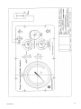
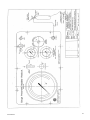
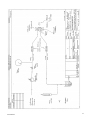
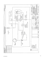
Gauge Pneumatic Bubbler Readout Model 1103/1103hp User Manual Man 136 2.0.1 06/08/2014 C. Spalton Andy Small Chris Rasmussen Manual No. Revision Date Originator Checked Authorised for Issue User Manual 1 Contents Section 1 : FOREWORD ................................................................................................... 3 Section 2 : INTRODUCTION............................................................................................. 4 Section 3 : EQUIPMENT SUPPLIED .................................................................................. 5 3.01 3.02 Equipment....................................................................................................... 5 Accessories...................................................................................................... 5 Section 4 : GENERAL DESCRIPTION ................................................................................ 6 Section 5 : PERFORMANCE .............................................................................................. 7 5.01 5.02 Model 1103 ..................................................................................................... 7 Model 1103-HP ................................................................................................ 7 Section 6 : PREPARING THE READOUT FOR USE .............................................................. 8 Section 7 : CHARGING THE NITROGEN CYLINDERS ......................................................... 9 Section 8 : TAKING READINGS ...................................................................................... 10 8.01 8.02 8.03 Section 9 : 9.01 “NO FLOW MODE METHOD” ............................................................................. 10 "FLOW MODE METHOD" .................................................................................. 11 GENERAL NOTE ON TAKING READINGS ............................................................. 11 TROUBLE SHOOTING ................................................................................... 12 Leaking in the Pneumatic Circuit ...................................................................... 12 Section 10 : CARE AND MAINTENANCE............................................................................ 13 Section 11 : HEALTH AND SAFETY REQUIREMENTS ......................................................... 14 User Manual 2 Section 1 : Foreword It is essential that the equipment covered by this manual is both installed and operated by competent and suitably qualified personnel. They must READ AND UNDERSTAND the procedures outlined in this manual before attempting installation or operation of the equipment on site. Failure to do this may result in degraded performance and reduced reliability. All systems are designed to operate consistently under normal field conditions. The Gauge Pneumatic Bubbler Readout is a precise and sensitive instrument which must be handled with the same care as sensitive surveying instruments. Although the components are relatively robust for such sensitivity they will not survive mishandling or neglect. Treat all items with respect and HANDLE WITH CARE. Obviously these techniques can only serve as a general guide and will require modification to suit particular circumstances on site. If difficulties are encountered time will usually be saved by contacting Soil Instruments Ltd at the earliest opportunity. SAFETY NOTE. This readout contains pressure reservoir cylinders which have been tested and certified in accordance with "Home Office" requirements. The cylinder must be retested and certified every five years in accordance with BS 5430 Part 3 or overseas in line with the local regulations. It is also a UK requirement that when a charged readout unit is transported on public roads that both the unit and the vehicle carry a non-flammable compressed gas hazard label. User Manual 3 Section 2 : Introduction The Bourdon Gauge Pneumatic Bubbler Readout is a portable readout unit for use with all Soil Instruments pneumatic transducers (and other manufacturers instruments) which operate on the "NO FLOW" or "FLOW” principle. A schematic drawing of the basic principle of operation of the pneumatic transducer system is given in Drg. A3/1103 -008. In this measuring technique the pressure to be monitored is caused to act on one side a sealed flexible rubber diaphragm in the transducer unit which is thus held against the back plate by the applied pressure. Two ports are drilled through the back plate surface and connected to nylon tubes which extend to the reading point. Referring to Drg. A3/1103-008, when a reading is required, gas pressure is applied to the black (send) tube and the magnitude is increased via the pressure regulator until it becomes greater than that of the hydraulic pressure acting on the other side of the diaphragm. The diaphragm moves away from the pneumatic ports and gas passes into the return tube. As bypass continues in the return tube, gas is detected visually by the air bubbles escaping at a water pot or through a flowmeter. A flow control valve is adjusted to reduce the return line gas flow to a minimum. This stable balance pressure is read directly from the Bourdon Tube Test Gauge on the front panel. User Manual 4 Section 3 : Equipment Supplied Pneumatic Readout Model 1103 consists of the following items. The Pneumatic Bubbler Readout is housed in a strong high impact polypropylene moulded case with a hinged sealed lid and carrying handle. The readout is connected to pneumatic instruments through two quick release couplings and fly tubes provided as accessories. 3.01 Equipment Gauge Type Pneumatic Bubbler Readout (Model 1103) housed in yellow moulded box. Dimensions : 360 x 280 x 160mm. Weight : 7 Kg. 3.02 Accessories Pair of 2m long nylon flyleads with quick release couplings to connect Readout with pneumatic instruments through a terminal panel. Single High Pressure nylon tube with end fittings to connect readout to external industrial Nitrogen cylinder regulator for recharging internal gas cylinder. Pair of safety goggles for use when recharging internal gas cylinder. User Manual 5 Section 4 : General Description The front panel is shown in Drawing No. A3/1103-006. All main parts involved in operation and function of the readout are located on the front panel except for the gas bottles and pneumatic tubes. Identification with brief function description is as follows; A. Pressure Control Valve. It has three positions as marked on the front panel. It connects the send line to regulated gas pressure or exhaust as shown in Drawing No. A3/1103 -009. B. Flow Control Valve. It is a needle valve which controls the gas flow rate into the send line Ref. Drawing 1103-009. C. Pressure Regulator. It is located between high pressure gas cylinders and the operational part of pneumatic circuit. Turning it clockwise increases the regulated i.e. operating, pressure and anticlockwise to reduce or completely shut the gas pressure. D. Regulated Pressure Gauge 0-200 psi. Indicates the operating pressure to which the send line and pneumatic sensor will be subjected on switching Valve "A" to apply pressure position. This should always be slightly higher than the expected reading. E. Flow Meter. Floating ball type with flow rate of 20 to 30 ml per minute. F. Cylinder Pressure Gauge. 0 to 1000 psi. This indicates the gas pressure in the internal cylinders. Maximum gas charging pressure of 950 psi may not be exceeded while charging the nitrogen. G. Bourdon Tube 6" Test Gauge. Depending on the range of pneumatic instruments the gauges can range from zero to 20, 40, 60, 100m Hd or zero to 200 or 350m Hd (1103 HP). H. Flowmeter connection to front panel. Quick release fitting for return line. Quick release fitting for send line. "Nitrogen" Nitrogen Gas charging point. User Manual 6 Section 5 : Performance The general description and operational procedures described in this manual are common to Model 1103low and high pressure Pneumatic Bubbler Readouts. Higher pressure readouts i.e. 0 to 200m Hd and 0 to 350m Hd will consume greater volumes of gas for same number of readings. The user is hence advised to prepare for more frequent nitrogen gas charging for higher ranged Readouts. The performance specifications are limited by the operating pressures and the range of test gauge in the readout which is as follows:- 5.01 Model 1103 Fitted with 6" Test Gauge Ranges of 0 to 100m Hd. Gauge Ranges available: 0 to 20, 40, 60 and 100m Hd. Gauge Reading Accuracy: ± 0.5% F.S.D. 5.02 Model 1103-HP Fitted with 6" Test Gauges Range of 0 to 350m Hd. Gauge Ranges available: 0 to 200 and 0 to 350 m Hd. Gauge Reading Accuracy: ± 0.5% F.S.D. User Manual 7 Section 6 : Preparing the Readout for Use Before embarking on a visit to site to take a series of readings it is important to ensure that the readout is properly prepared as follows; 1. Ensure that all items are available i.e. Readout, pneumatic flyleads, cleaning materials for cleaning couplings and notepad/pencil for recording readings. 2. The internal Nitrogen cylinders must be sufficiently charged to ensure enough gas is available for the readings to be taken (refer to Section 7 for charging details). In case of high pressure readings greater quantity of gas per reading will be consumed. A careful planning of recharging the gas cylinders is advised to save trips back to base especially over long distances. User Manual 8 Section 7 : Charging the Nitrogen Cylinders Refer to Drg. No. A3/1103-007 WARNING The regulator fitted to external nitrogen cylinder controls the charging pressure eliminating any chance of accidentally over pressurising the nitrogen reservoir in the readout. However the operator MUST ALWAYS watch the gauges and never exceed an indicated CYLINDER PRESSURE of 65 bar (950 psi) while adjusting the regulator setting during charging operation. 1. Remove dust cover from bulkhead fitting marked NITROGEN on the front panel. 2. Examine charging flylead and ensure it is undamaged and end fittings are in good clean condition. 3. Wear Safety Goggles for the following procedures. 4. Ensure Pressure Regulator Valve on the deliver cylinder is closed by turning adjustment knob fully anticlockwise. 5. Connect flylead from readout to regulator on delivery cylinder. Do not over tighten the brass coupling nuts (it is only necessary to use two fingers on the spanner when tightening the nuts). 6. Using special cylinder key open delivery cylinder valve. 7. Slowly open pressure regulator on delivery cylinder by turning the adjustment knob clockwise until flow is heard, accompanied by a rising pressure indicated on the readout CYLINDER PRESSURE GAUGE "F". 8. Continue to turn the delivery cylinder regulator knob clockwise in stages. Wait until the readout cylinder pressure gauge stabilises before continuing. 9. When the readout cylinder pressure gauge registers 65 Bar (950 psi) close off delivery cylinder with the key. 10. Close Pressure Regulator Valve by turning adjustment knob on delivery cylinder regulator fully anticlockwise. 11. Carefully remove flylead by slightly loosening brass nut at readout connection marked "NITROGEN". Allow residue of pressure in flylead to exhaust completely before disconnecting flylead. INFORMATION Always make sure that the flylead is never left connected to the cylinder regulator when not in use. This will prevent "whip-lash" of the flylead in the event of the delivery cylinder valve being accidentally opened. 12. Replace dust cap on "NITROGEN" fitting. User Manual 9 Section 8 : Taking Readings All pneumatic instruments of 3P5.2, 3W5.20, 7P5.1 and 8P2.12 type can be read with this readout using "No Flow" or "Flow Mode" of reading. It is advised that one of the two modes is always used to avoid variance in readings. The two methods are described below. 8.01 “No Flow Mode Method” Refer to Drg.No. A3/1103-006. Connect the Pneumatic Readout to the instrument desired to be read either directly or through the terminal panel. Make sure that quick release couplings are clean and dry. Set Valve "A" to "EXHAUST" position and open Flow Control Valve "B" (turn knob anticlockwise 1 to 2 turns). This exhausts the system to atmosphere making the gauge read zero pressure. 1. Close Valve "B" (screw in gently). 2. Set Valve "A" to "OFF" position. 3. Adjust Pressure Regulator "C" to indicate an output pressure on gauge "D" just in excess of expected reading. 4. Set Valve "A" to APPLIED PRESSURE position. 5. Slowly open FLOW CONTROL Valve "B" (approximately 1/4 turn only) and observe the gauge "G". The reading should slowly rise. Adjust control Valve "B" as necessary to maintain steady increase on gauge "G". After delay (dependent on installed tube lengths) the Flowmeter "E" will indicate gas returning by the float rising in the flowmeter. Adjust flow control Valve "B" to maintain the correct flow, the ball should float between the two indicator lines. 6. Allow flow to continue for approximately 20/30 seconds. 8.1.7 Set Valve "A" to "OFF" position. 7. Reading on the Test Gauge "G" will settle at the balanced pressure and is recorded. 8. Reading may be repeated as a check by resetting Valve "A" to "APPLY PRESSURE" position repeating from Step 2. 9. On completion of readings set Valve "A" to EXHAUST position. Decrease Pressure Regulator "C" to zero pressure (shown on Gauge "D") and open Flow Control Valve "B". Set Valve "A" once again to APPLIED PRESSURE to exhaust the control circuit of residue gas. 10. Finally reset Valve "A" to "OFF" position. 11. Disconnect flyleads and protect fittings with dust caps. User Manual 10 8.02 "Flow Mode Method" This method of reading is less convenient due to time necessary to accurately maintain a constant low gas flow rate throughout the reading cycle. To obtain the most accurate reading a minimum gas flow must be achieved to "just open" the diaphragm valve in the installed pneumatic transducer. To achieve this requirement the flow rate must be adjusted to maintain the flowmeter ball floating on the lower indicator line in the flow tube. 1. This reading method is identical to the "NO FLOW MODE" method up to step 8.1.6. Further steps are as follows. 2. Refine flow rate adjustment to float the ball on lower indicator line. 3. Take the reading on Gauge "G" and record it. This completes the sequence of one reading. Repeat readings or other transducers can be read using same sequence again. 4. After completion of a set of readings, exhaust the pneumatic lines by turning Valve "A" to "Exhaust" and "B" to open position (2 turns anticlockwise). Disconnect the readout pneumatic flyleads and cover fittings with dust caps. 8.03 General Note on Taking Readings When carrying out a reading sequence avoid applying excessive flow rate setting by careful adjustment of "FLOW CONTROL Valve B". Never intentionally allow the flowmeter ball to float to the top of the flow tube; this may give rise to inaccurate readings. Should application of excessive gas flow occur it is important to re-set Valve "A" to "OFF" position and allow the flowmeter ball to return to the bottom of the flow tube. A period of several minutes delay should be allowed (depending on tube lengths) before carrying out a new reading sequence. This ensures that any over pressure in the installed instrument tubes dissipates before attempting to carry out further readings. User Manual 11 Section 9 : Troubleshooting Faults due to failure of mechanical components may be divided into two categories. Those due to leakage in the pneumatic circuit lines and those due to the failure of moving components such as valves and mechanical linkages. 9.01 Leaking in the Pneumatic Circuit The most critical part of the pneumatic circuit is that relating to the send line. Here the smallest of leaks will produce a continuing fall off of indicated pressure at the reading phase rendering the unit unusable. Should leaking be suspected, proceed as follows; 1. Ensure the nitrogen cylinders are charged. 2. Remove the front panel of the readout and fix so that both faces are accessible. 3. Set the readout in the operating mode by setting valve "A" to "APPLY PRESSURE" position, open Control Valve "B" half turn and adjust PRESSURE REGULATOR "C" to indicate a typical output pressure on gauge "F". Ensure symptom is apparent. 4. Listen for sound of leaking gas. Locate leak by ear and touch. 5. If nothing is heard take a length of flexible tubing and use as a stethoscope, moving one end over the area of the circuit where a leak is suspected. 6. If the above measures fail to positively locate the leak, paint all joints with a soapy water solution and inspect for bubbles. 7. Leaks at tube connections/fittings may be sealed in most cases by carefully tightening the offending fitting. 8. Reset valves "A" to "OFF" and "B" to Close (fully clockwise) and adjust regulator "C" to off position (full anticlockwise). 9. Should the leak remain undetected it is likely that a valve is leaking internally. The offending valve must be stripped, examined and cleaned. Apply a thin film of light oil over the seals before re-assembly. Should the leak persist after the above action has been taken a replacement valve should be sought. User Manual 12 Section 10 : Care and Maintenance The Unit is basically a simple pneumatic system and requires little maintenance other than general cleaning of the box and panel after use on site, particularly the quick-connect couplings. The unit should be protected from heavy rain or excessive moisture (it must never be immersed in water) and if such conditions are prevalent on the site arrangements must be made to dry out the readout after use. Always take great care to avoid ingress of water into the pneumatic circuits as this is the primary cause of problems with this type of Readout. Care should be taken to avoid damage by dropping the readout since this may affect the calibration of the Test Gauge. More severe abuse will cause serious damage and can be dangerous as the unit contains compressed gas cylinders. For long term accuracy of readings it is advisable to arrange for periodic calibration check of the Test Gauge. The intervals between checks would depend on usage but is advised that the unit should be checked annually at least. User Manual 13 Section 11 : Health and Safety Requirements The readout unit contains steel high pressure gas cylinders which have been tested and certified in accordance with "Home Office" requirements. The gas cylinders must be retested and certified every 5 years in accordance with BS 5430. The date of last certification is shown on a test label attached to the neck of the cylinders. Soil Instruments will carry out the test on return of the readout. Alternatively the cylinder may be re-certified by any recognised authority. Most Insurance Companies can arrange for this service. When transported on the public road it is a requirement that the unit and the vehicle in which it is being carried carry the non-flammable compressed gas hazard label. Bell Lane, Uckfield, East Sussex t: +44 (0) 1825 765044 e: [email protected] TN22 1QL United Kingdom f: +44 (0) 1825 744398 w: www.itmsoil.com Soil Instruments Ltd. Registered in England. Number: 07960087. Registered Office: 5th Floor, 24 Old Bond Street, London, W1S 4AW User Manual 14 User Manual 15 User Manual 16 User Manual 17 User Manual 18