1
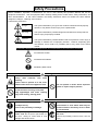
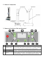
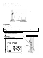
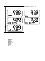
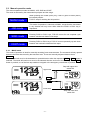
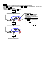
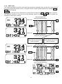
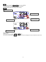
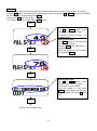
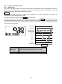
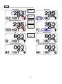
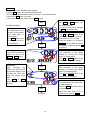
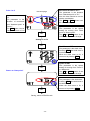
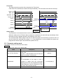
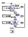
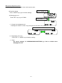
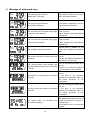
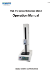
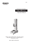
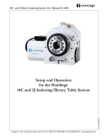
97591A FGS-VC Series Motorized Stand Operation Manual Read Manual thoroughly prior to operation. Use instrument only after reading the complete manual. Follow all safety precautions. Safety Precautions Before Installation, Operation or Maintenance, be sure to read carefully this Operation Manual and use the equipment as directed. Use the equipment after carefully reading all the caution items, safety information, and other discriminations. In this User’s Manual, the Safety Awareness Items are divided into three different categories: “Danger”, “Warning” and “Caution”. Follow these precautions. Danger This symbol indicates if you ignore the contents mentioned and improperly operate, it may lead to serious injury from a potential fire. Warning This symbol indicates a potential dangerous situation that could produce a Serious injury if improperly handled. Caution This symbol indicates a potential situation that could produce a minor injury or Damage to material if it is improperly handled. However, depending upon the situation, there could be a possibility that it may cause more serious results. Protection categories are explained and separated by the following symbols. Proceed with Caution. Not Allowed-Prohibited. Mandatory-Must Follow Warning Heavy! Take sufficient care while handling. Ensure stand is placed on a flat, level, stable surface that can support the unit. Do not operate in areas where explosive gases or vapors may be present. Do not touch the running, inner parts. Keep appendages and loose clothing away from running, moving parts. Caution Fix object surely. There is the possibility of damage. Hold power plug while removing the power cord. Do not pull or put tension on the cord. Doing so could result in cord damage and electric shock Do not install in a high humidity environment or near where water may be present. Electric shock may occur if water is encountered. Never carry or move the FGS-VC with the AC code. There is the possibility of electric shock, a fire and injury. Confirm that the power supply is the same voltage rating as the displayed voltage rating on the unit Do not plug AC connector with wet hand. There is the possibility of electric shock. Attention Safety Warning Disconnect from the AC outlet during any maintenance of the stand. Also, unplug when not using for long periods of time. May cause electric shock, a fire and injury. Attention before using FGS-VC Avoid the following. Place where water, oil, or medicine may splash Dusty locations Places where condensation occurs Places where explosive gases or ignition sources are present. Place where high vibration may occur Places outside of operating temperature range. 32-104°F (0-40°C) Cleaning with thinner and gasoline, etc. Make sure the cable is not stuck in the stand. Install the force gauge after turning off the power switch. Adjust the limit switches when the motor stops. When digital force gauge FGV series is installed Set "ovEr" in the F06 parameter, which is the parameter of Output Type. If "ovEr" is not set, FGS-VC does not stop by the overload of the force gauge. Index 1. Prior to use ................................................................................................................................................... 1 1.1. Procedure from the Installation of a force gauge to the measurement ............................................ 1 1.2. Confirmation of product packing ........................................................................................................ 1 2. Names of components.................................................................................................................................. 2 3. Names and functions of the operation panel ............................................................................................. 2 4. Setup............................................................................................................................................................. 3 4.1. Installation of force gauge ................................................................................................................... 3 4.2. Connection of force gauge to the stand ............................................................................................... 4 4.3. Connection of PC to the stand ............................................................................................................. 5 5. Operation ..................................................................................................................................................... 5 5.1. Basic operation flow ............................................................................................................................. 5 5.2. Operation mode .................................................................................................................................... 7 5.3. Manual operation mode ....................................................................................................................... 8 5.3.1. MANU mode .................................................................................................................................. 8 5.3.2. JOG mode ...................................................................................................................................... 9 5.3.3. SING mode .................................................................................................................................. 11 5.3.4. CONT mode ................................................................................................................................. 14 5.4. Program operation mode ................................................................................................................... 17 5.4.1. PROG mode ................................................................................................................................. 17 5.5. Parameter setting mode .................................................................................................................... 21 5.6. Changing Engineering units ........................................................................................................... 23 6. Message of status and error...................................................................................................................... 24 7. Dimensions................................................................................................................................................. 25 8. Specifications ............................................................................................................................................. 27 9. Troubleshooting ......................................................................................................................................... 27 1. Prior to use 1.1. Procedure from the Installation of a force gauge to the measurement FGS-VC can measure various loads using Shimpo's digital force gauges which are FGV series. Confirm the following procedures before use. Confirm the parameter Install the force gauge. setting of the force gauge Connect the cables. Problem Troubleshooting Measure each mode. 1.2. Confirmation of product packing FGS-VC Cable clip Hex-head spanner Socket bolt (M6 x 16mm) 1 1 1 2 Cable to force gauge USB cable (2m) Bolt (M8 x 8mm) Set screw (M6 x 20mm) 1 1 4 1 Washer 2 Manual 1 -1- 2. Names of components Upper limit Knob Force gauge plate Lower limit knob Emergency switch Measurement table Operation panel 3. Names and functions of the operation panel 2 3 1 No 4 12 5 6 Name 1 Emergency switch 2 3 Speed key (up) Speed key (Down) 4 MAX key 11 7 10 8 9 Description Emergency stops when pushing. Push the switch when FGS-VC acts abnormally or a potentially dangerous situation is occurring. Release the emergency stop to restart operation. Increase or decrease the speed when pushing the up or down arrows of the Speed key. If the up or down arrows are held, the speed adjusts continuously. Push to override the current speed setting. The speed will instantly go to the maximum capable of the stand. Once released, the speed returns to the previous speed setting. This key only is functional in Manu or Jog modes. -2- 5 6 7 8 9 10 MODE key SET key START key PUSH key STOP key PULL key 11 ZERO key 12 LCD display LCD display Change operation modes or function settings. The indicated data is set when the key is pushed. Start the program mode operation Move in the PUSH direction. Stop operation. Move in the PULL direction. Clear distance in Manu and Jog modes. Clear repeat time in Sing, Cont and Prog modes. Displays distance, speed and mode, etc. Main display Sub display Status display 4. Setup 4.1. Installation of force gauge Remove the mounting plate using the hex-head spanner accessory. Set the force gauge in the mounting plate. Fix the mounting plate with the force gauge to the stand using supplied bolts. The force gauge is set in the mounting plate. In case of FGS-220VC The force gauge is fixed to the stand. Force gauge that can be connected with FGS-VC is FGV series. Force gauges up to 100kgf are compatible with the FGS-220VC. Force gauges up to 200kgf are compatible with the FGS-550VC. -3- 4.2. Connection of force gauge to the stand The connection and confirmation between FGS-VC and a force gauge is the following procedure. Parameter setting of the force gauge Set the following parameters. Measurement polarity: + RS232C baud rate: 19,200 bps Refer to the manual of the force gauge. Connect to FGS-VC Connect the force gauge to FGS-VC by the attached cable. Power on Turn on the power of the force gauge. Next, turn on FGS-VC with the power switch on the back. 22 55 Confirmation of the connection Display of FGS-VC as follows: 1. Indicates "FGS-220VC". 2. Indicates "MANU"(Manual Mode) If the connection is wrong, 2. Indicate "NO FORCE GAUGE" in 3 seconds, then indicate "MANU". If the connection is wrong, check: Are the parameter settings of the force gauge correct? Is the sequence of power on correct? Is the cable correct? If no problem, please contact our technical support. -4- 22 4.3. Connection of PC to the stand FGS-VC can connect to PC for taking force and displacement. The software is able to be downloaded from Shimpo's website free of charge. Refer to the software manual. Cable between FGS-VC and force gauge USB cable Personal computer 5. Operation 5.1. Basic operation flow The procedure of basic operation is described as follows. Keep hands, hair and jewelry away from stand when drive assembly is in motion. May cause damage or injury. Force gauge power Turn on the power of the force gauge. Example. Tension test of a wire FGS-VC power Turn on the power of the stand. Separate hands from the force gauge and FGS-VC movable parts. Turn on FGS-VC. 22 55 0 Display appears as below: A wire Wedged chuck -5- Solderless terminal Select measurement mode Select Manual, Jog, Single, Continuous and Program mode according to the measurement purpose and the usage. Mode can be changed by the Mode switch. Start to measure. Start each mode by pressing PUSH, PULL or START switch. Refer to each mode section. FGS-VC is able to test as follows: Compression test Tension test Welding test Peel test Suction test Repulsion test Cork test Open test Etc. -6- 5.2. Operation mode The operation mode consists of manual and program. The mode is selected by the measurement purpose and the usage. You wish to test by PUSH or PULL key. e.g., You want to move to the position of PULL limit by pressing PULL switch. You want to move only while you press the PUSH key. You want to move the round trip operation many times between limits of PUSH and PULL. etc. Select manual operation modes : MANU, JOG, SING, CONT.. You wish to move complex operations. e.g., You want to measure by specifying the positions. The position of the object to be measured cannot be specified. You want to combine a different direction (PUSH/PULL) of operation with a test. etc. Select Program operation mode. How to select the mode? Pressing MODE switch in the Operation panel, the mode changes one by one as follows. A present operational mode is displayed under the left of LCD. MANU mode MODE JOG mode MODE MODE Parameter setting mode SING mode MODE MODE PROG mode -7- MODE CONT mode 5.3. Manual operation mode The manual operation modes are MANU, JOG, SING and CONT. The mode is selected by the measurement purpose and the usage. MANU mode When pressing the PUSH (PULL) key, FGS-VC goes to PUSH (PULL) limit switch position. FGS-VC stops if reaching the limit position. JOG mode This mode of operation is identical to MANU, except that the movement in any direction will only occur while either the PUSH or PULL key is depressed. SING mode Pressing PUSH or PULL keys, FGS-VC moves for one complete cycle between mechanical distance limit stops. CONT mode Pressing PUSH or PULL keys, FGS-VC moves repeatedly up and down between the mechanical distance limit stops. 5.3.1. MANU mode This mode of operation is ideal for manually recording force measurements. The test stand will only operate between the limits that are set by the test stand user. These are manually adjusted distance limits. Contents The test stand will move in the downward or upward direction when the respective PUSH or PULL button is selected. The stand will continue to move in the selected direction until one of the following occurs: STOP button is pushed, one of the limit stop switches is tripped or the emergency reset button is pushed. Stop with upper limit switch ON Upper limit PULL PUSH LL Lower limit Stop with lower limit switch ON -8- Speed Speed can be changed by UP or DOWN button of the SPEED. The speed setting of MANU and JOG mode is common. Also the speed is able to be changed while moving. Display Present position Setting speed Parameter The speed of MANU and JOG modes is adjustable. Press the SET button to enable adjustment via the UP or DOWN buttons of the SPEED key. Then press the SET button to save the new value. If you want to cancel the setting press the ZERO button. Setting speed The UP or DOWN button of the SPEED key can be used to change the speed. The range is 0.40-15.75in/min (10to400[mm/min]]. 5.3.2. JOG mode Contents This mode of operation is identical to MANU mode, except that the movement in any direction will only occur while either the PUSH or PULL button is depressed. Speed Speed can be changed by UP or DOWN button of the SPEED key. The speed setting of MANU and JOG mode is common. Also the speed is able to be changed while moving. Display Present position Setting speed -9- Parameter The parameter, which is the speed of MANU and JOG mode, is available. Pressing SET button, and the speed can be changed by UP or DOWN key of the SPEED. Then press SET button for saving. If you want to cancel the setting, press ZERO button. Setting speed The UP or DOWN button of the SPEED key can be used to change the speed. The range is 0.40-15.75 in/min (10 to 400[mm/min]. - 10 - 5.3.3. SING mode This mode of operation is ideal for completing one cycle between mechanical, manually adjusted distance limit stops. The test stand will only operate between the limits that are set by the test stand user. Contents The test stand will move downward or upward when the respective PUSH or PULL button is selected. The stand will continue to move until one of the following events occurs: the STOP button is pushed, one of the limit switches is tripped or the emergency reset button is pushed. Stop with upper limit switch ON with dwell timer Push speed PULL Pull speed Upper limit Display alternately Lower limit Stop and complete with lower limit switch ON Stop and complete with upper limit switch ON Push speed PUSH Pull speed Upper limit Display alternately Lower limit Stop with lower limit switch ON with dwell timer - 11 - Speed Speed can be changed by UP or DOWN button of the SPEED key. The speed setting of SING and CONT mode is common. Also the speed is able to be changed while moving. Display Present position Setting speed Moving direction Repeat count Setting dwell timer Status of limit switch Repeat count Incremental count at pressing PUSH or PULL button. The count is cleared with the ZERO button. When the mode is changed, the count will also be reset to zero. - 12 - Parameter The parameter, which is the dwell timer and the speed of pull and push, is available. Pressing SET button, the speed can be changed by UP or DOWN button of the SPEED key. The dwell timer can be changed by STOP. Finally press SET button for saving. If you want to cancel the setting, press ZERO button. SET Setting speed The UP or DOWN button of the SPEED can be used to change. The range is o.40-15.75 in/min(10 to 400 [mm/min]. Setting dwell timer The STOP button of the dwell time can be used to change. Pressing STOP, the dwell timer is incremental. When the dwell timer is 5s, it returns to 0s pressing STOP. SET SET Saving, return to SING mode - 13 - Push speed PULL Pull speed 5.3.4. CONT mode This mode of operation is ideal if the user wants the test stand to repeatedly cycle up and down continuously or for a user-programmed number of times. The stand will start in either direction depending on whether PUSH or PULL button is selected. Contents The test stand will start to move downward or upward when the respective PUSH or PULL button is selected. The stand will continue to move until one of the following events occurs: the STOP button is pushed, the emergency reset button is pushed. Stop with upper limit switch ON with dwell timer Upper limit A B Lower limit Stop with lower limit switch ON with dwell timer Complete with lower limit switch ON when the repeat count is reached. Complete with upper limit switch ON when the repeat count is reached. Stop with upper limit switch ON with dwell timer Upper limit Push speed PUSH Pull speed A B Lower limit Stop with lower limit switch ON while dwell timer A B Display alternately - 14 - Speed Speed can be changed by UP or DOWN button of the SPEED. The speed setting of SING and CONT mode is common. Also the speed is able to be changed while moving. Display Present position Setting speed Moving direction Repeat count Setting dwell timer Status of limit switch Repeat count Incremental count at pressing PUSH or PULL button. The count is cleared with the ZERO button. When the mode is changed, the count will also be reset to zero. - 15 - Parameter The parameter, which is the repeat times and the dwell timer and the speed of pull and push, is available. Pressing SET button, the speed and the repeat times can be changed by UP or DOWN button of the SPEED key, the dwell timer can be changed by STOP. Finally press SET button for saving. If you want to cancel the setting, press ZERO button. SET Setting speed The UP or DOWN button of the SPEED can be used to change. The range is 0.40-15.75 in/min 10 to 400[mm/min]. Setting dwell timer The STOP button of the dwell time can be used to change. Pressing STOP, the dwell timer is incremental. When the dwell timer is 5s, it returns to 0s pressing STOP. SET SET Setting dwell timer The UP or DOWN button of the SPEED can be used to change. The maximum value is 9999. When the display is o and press DOWN it will be 9999, and when the display is 9999 and press UP it will be 0. SET Saving, return to SING mode - 16 - 5.4. Program operation mode 5.4.1. PROG mode This mode of operation is ideal if user wants to operate the test stand with complex programmed movements. Even if the user does not know the length of the object, the accurate measurement is possible because the function to detect the object to be measured is provided. Contents The programmed data consists of a condition setting, starting point, a method of detection of the object, five measurement points and a method of return. The test stand will start to move when START button is pressed. The stand will continue to move until one of the following events occurs: the STOP button is pushed, one of the mechanical limit switches is tripped, the emergency reset button is pushed or the overload of the force gauge is detected. If the force limit of the condition setting is detected, the present operation is interrupted and it will jump to next point operation. Upper limit Start point Standard point Detect point Point 1 Point 5 Point 3 Point 2 Point 4 Lower limit Example Start point Detect point Standard point Point 1 to 5 Program start point and return point Object detected point according to the condition Standard point for measurement Programmed point - 17 - Display The example of the display under operation is shown below. Detect point Present position Start point Moving direction Start point (Dwell timer) Operation status P1 Setting speed P3 P3 (Dwell timer) Present repeat times status Return to Start point Return to Start point (Dwell timer) - 18 - Parameter The parameters are available while stopping. Pressing SET button, the parameter setting starts. The contents of the parameters setting is shown in the below flowchart. Finally press SET button for saving. If you want to cancel the setting, press ZERO button. Force limit The PUSH or PULL button can be used to change. The sign of force limit is changed by MAX button alternately. SET Condition setting Moving direction The parameter is the direction of movement from “Start point” to “Detect point”. The STOP button can be changed to Push or Pull alternately. Repeat times The UP or DOWN button of the SPEED can be used to change. The maximum value is 9999. When the display is o and press DOWN it will be 9999, and when the display is 9999 and press UP it will be 0. SET Speed The parameter is the speed setting for moving from "Start point" to "Detect point". The UP or DOWN button of the SPEED can be used to change. Detect object The force for detecting object can be set by PUSH or PULL button. Zero force After detecting the object, the stand moves to opposite direction until sensing the force less than the setting force data. The PUSH or PULL button can be used to change. Speed The parameter is the speed setting for moving from "Detect point" to "Standard point". The UP or DOWN button of the SPEED can be changed. SET SET Next page - 19 - Dwell timer The parameter is the dwell timer at "Standard point". Pressing STOP, the dwell timer is incremental. When the dwell timer is 5s, it returns to 0s pressing STOP. Point 1 to 5 Previous page Movement direction at P1 The parameter is the direction of movement from “Standard point” to “Point 1”. The MAX button can be changed to Push or Pull alternately. SET Movement Distance at P1 The parameter is the distance from "Standard point" to "P1". Also the data should be set as relative coordination. The PUSH or PULL button can be used to change. Speed at P1 This parameter is the speed setting for moving from "Start point" to "Detect point". The UP or DOWN button of the SPEED can be used to change. Setting P2 to P4 SET SET Return to “Start point” Dwell timer at P5 This parameter is the dwell timer. Pressing STOP, the dwell timer is incremental. When the dwell timer is 5s, it returns to 0s pressing STOP. Speed at RET This parameter is the speed setting for moving from "Point 5" to "Start point". The UP or DOWN button of the SPEED can be used to change. Dwell timer at RET This parameter is the dwell timer. Pressing STOP, the dwell timer is incremental. When the dwell timer is 5s, it returns to 0s pressing STOP. SET Saving, return to PROG mode - 20 - Force limit The stand controls to give the force less than the "Force limit". If the force limit is detected, the stand will stop immediately. Then the stand executes the next step. Upper limit Start point Standard point Detect point Point 1 Point 5 Point 5 Point 3 Point 2 Point 4 Point 4 Lower limit Detect the force limit Example Detect object The parameter is the threshold force level for detecting the object. When the setting force of "Detect object" parameter is detected, the stand will stop immediately. Next the stand moves to opposite direction until detecting "Zero force". The recommended "Detect object" that the user should program into the stand is more than 0.2% of the full scale of the mounted force gauge, i.e., if the programmer is using a 200lb force gauge, the programmed "Detect object" should be 0.4lb (200lb x 0.2%). 5.5. Parameter setting mode The relations function is set to the entire stand. Contents The parameters are shown in the below table. Items Sign of Push direction Acceleration Volume of buzzer Description The sign at the position of the direction of Push is set. If it sets "-" and the stand moves to Push, the display of position is decrement. The acceleration of the motor of the stand is set. The acceleration is the slope or rate of increase in speed from the non-motion starting point to the set programmed speed. If the parameter is set at a maximum of 100, the motor will accelerate quickly The volume of the buzzer is adjusted. - 21 - Range [space], - 1 to 100 (step 1) OFF, Low, Middle, High Parameter If you want to cancel the setting, press ZERO button. Sign of Push direction Space means '+'. Adjust with the UP or DOWN buttons. Pressing the button, the setting will be changed alternately. MODE Save and go to MANU mode SET Acceleration Adjust with the UP or DOWN buttons. MODE Save and go to MANU mode SET Volume of buzzer Adjust with the UP or DOWN buttons. MODE Save and go to MANU mode SET - 22 - 5.6 Chaning Engineering Units I①Change distance and speed units in the function mode. Press “MODE” key a)Function settings Press “ MODE” key to go to function settings b)Changing the unit Press “SET” key to go to FUNC4. Press “SET” inch c)Change in the displayed unit Pressing the “PUSH” or “PULL” keys changes the units from inch to mm UNIT Press “PUSH” or “PULL” key inch UNIT mm UNIT d)Registration of the unit Press “SET” or “MODE” key to finish the setting e)Note: The speed settings of JOG/MANU/SING/CONT/PROG go back to default when changing the units. - 23 - 6. Message of status and error The lower limit was reached. “PUSH LMT” is blinking. If the status is abnormal, move the lower limit switch position. The upper limit was reached. “PULL LMT” is blinking. If the status is abnormal, move the upper limit switch position. The over load of the mounted force gauge occurred in push direction. The over load of the mounted force gauge occurred in pull direction. The emergency stop was pushed. The motor or the driver of the motor was abnormal. The communication error between the controller and the motor driver in the stand occurred. The read error of the memory in the stand occurred. The write error of the memory in the stand occurred. 22 The stand could not recognize the mounted force gauge. - 24 - Confirm whether the force gauge used is correct. Check whether the measurement is abnormal. Confirm whether the force gauge used is correct. Check whether the measurement is abnormal. Confirm that a problem is not found, then release the emergency stop. Turn off and wait one minute, then turn on. Contact TECHNICAL SUPPORT if the alarm is not canceled. Turn off and wait one minute, then turn on. Contact to our technical support if the error alarm is not canceled. Turn off and wait one minute, then turn on. If the error is not canceled, initialize the parameter. Refer to the below procedure of the initialization. Turn off and wait one minute, then turn on. If the error is not canceled, initialize the parameter. Refer to the below procedure of the initialization. Check: The parameters setting of the force gauge, the sequence of power on and the cable. If no problem, ask to our technical support. Procedure of the initialization of the parameters 1. Turn off, wait one minute. 2. Press ZERO and SET button both, turn on in keeping to press these buttons. 22 7. Dimensions Upper limit 4.72 Force gauge: FGP, FGPX 34.84 Stroke: 15.75 Lower limit Emergency switch 3.94 2.95 2.95 19.69 11.81 FGS-220VC - 25 - 0.75 4.72 2.91 Operation panel [inch] 5.51 5.91 3.94 M8 [mm] M10 [mm] Plate FGS-220VC 2.26 Table FGS-220VC 2.95 4-0.18 0.79 0.79 1.95 5.91 2-0.35 0.79 1.77 1.57 1.20 3-0.22 0.35 1.18 1.97 0.39-1.26UNF 1.18 Table 7.87 3.94 7.87 M6 [mm] 5.91 1.31 adjustable 1.77 adjustable Table Adjust FGS-220/550VC - 26 - [inch] 8. Specifications Model FGS-220VC Capacity Travel Speed Stroke Display Operating Mode Communication 100kg (1,000N, 220lb) 10-400mm/min (0.40-15.75”/min) 400mm (15.75”) Dot-matrix LCD Four digit with sign MANU, JOG, SING, CONT, PROG USB Over load from force gauge (The stand will stop immediately, if the over load is detected.) 150 x 200mm (5.91 x 7.87”) 32-113 degrees Fahrenheit(0-45 degrees Centigrade) 120VAC/240VAC 63kg (139lb) 300 x 885 x 500mm (11.81 x 34.84 x 19.69”) USB cable Communication cable for force gauge(FGV series) Free software is provided. FGV-series Force gauge Input Measurement Table Operating Temperature Power Weight Dimensions Accessories PC Software Available Force Gauge 9. Troubleshooting The following are general checkpoints; please call your local Shimpo representative or contact Shimpo Instruments directly for further assistance. Even if the power supply is turned on, LCD doesn't display. The force gauge/load cell mounting plate does not move. The stand will not accept a program. The stand is noisy during operating. Confirm the voltage of the input supply. Check power connections and power source, ensure that test stand power is on. Check whether the load hangs too much. Check manual limit switches and adjust accordingly. Confirm whether the emergency switch is ON. Check the mounted force gauge is over load. Check to see if the full travel range has already been achieved. Check to be sure you are in the correct mode of operation. Move force gauge/load cell mounting plate to Home position. Check to see if you are in the correct mode of operation (PROG). If there is no abnormal condition, the sound of the motor and gears may still be high due to rapid movement. - 27 - Copyright© Nidec-Shimpo America Corporation 2013. All rights reserved. Product specifications are subject to change without notice. - 28 -