1
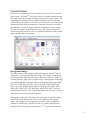
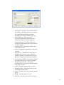
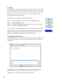
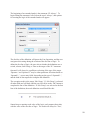
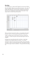
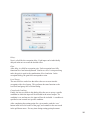
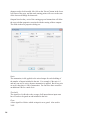
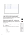
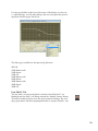
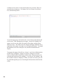
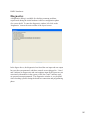
TM
Sonata
User Manual
Revision 8/15/2011
Contents
Layout Screen ....................................................................................................................1
Background Image ...................................................................................................1
Placing Layout Elements .........................................................................................2
Mixers ............................................................................................................2
Controls .........................................................................................................2
Doors .............................................................................................................4
Input ...............................................................................................................4
Output Zone ...................................................................................................4
Line Out .........................................................................................................5
Text ................................................................................................................5
Templates .......................................................................................................5
Level Groups .................................................................................................5
Template Editor .......................................................................................................6
Connecting Elements ...............................................................................................7
Panning/Zooming ....................................................................................................7
Programming Mixers .........................................................................................................8
Modes .................................................................................................................................8
Switches ...................................................................................................................9
Creating .................................................................................................................10
Creating Extended Modes .................................................................................... 10
Associations .....................................................................................................................12
Routing .............................................................................................................................14
Processing ........................................................................................................................17
Copy/Paste .............................................................................................................19
PEQ ........................................................................................................................19
1/3 Octave ..............................................................................................................21
ALC .......................................................................................................................21
Comp Limit ............................................................................................................21
Delay ......................................................................................................................22
High Shelf / Cut .....................................................................................................22
Low Shelf / Cut ......................................................................................................23
Signal Generator ....................................................................................................24
Tap Source................................................................................................................25
Tap Destination ......................................................................................................25
VU Meter ...............................................................................................................25
Ambient Source .....................................................................................................26
Ambient Level .......................................................................................................26
Triggers ............................................................................................................................27
Networking ......................................................................................................................29
Run/Simulate ...................................................................................................................31
Connecting to a Mixer .....................................................................................................33
Contexts/Layouts ...................................................................................................33
Associating/Disassociating Mixers ........................................................................34
Load/Push Layout ..................................................................................................35
Resetting Mixers ....................................................................................................35
Hardware Programmer .....................................................................................................35
RMPC Controls .....................................................................................................36
Diagnostics .......................................................................................................................37
Layout Screen
In SonataTM, the layout screen is not simply a place to put icons in some
logical order. In SonataTM , the layout screen is a window into the system,
and can be used for a number of purposes beyond just creating logic. By
expanding the capabilities of the graphical elements, and by including
feedback from the hardware, this screen can be used to do everything from
sophisticated marketing presentations of potential systems to customers,
to diagnostics of errors in programming or installation for new systems.
The detail in graphical representation is up to the system designer, but
even basic designs will have a level of graphical simulation to the system
unseen in other software packages.
Background Image
The first example of the graphical difference between SonataTM and it’s
competitors, is the layout background image. This image is loaded into
the background to make the layout space familiar to the user. Images of
working drawings, plan views, designer logos, custom graphic renderings,
even satellite photos are imported in any of the following formats: BMP,
GIF, ICO, CUR, JBG, JPG, JPC, JP2, PCX, PGX, PNG, PNM, RAS,
SKA, TGA, TIF, WBMP, WMF, RAW, CRW, NEF, CR2, DNG, ORF,
ARW, ERF, 3FR, DCR, X3F, MEF, RAF, MRW, PEF, SR2. The load
background icon (or the view, load background menu selection) is used to
select the file to be used as the background.
Background images are loaded into the layout space as top-left justified,
and with the same dimensions, colors, and resolution as the original
image. Any changes to the image that are needed, such as additional
whitespace around edges, should be made in a graphics manipulation
package before being imported into SonataTM. To clear the background
1
select ‘view, clear background’ from the main menu.
Placing Layout Elements
On starting up SonataTM for the first time, the user sees a white desktop,
with a grid overlay. This is the layout screen where all the elements of
the system will be placed, connected, defined, animated, and tested. The
layout screen has element placement aids, such as the grid, and snap-togrid features available on the toolbar. These aids can be turned off and on
by the click of a button.
To place any element type, right-click in the grid area to view the selection
pop-up menu, and select the element to be placed. Currently, the elements
that can be placed are mixers, controls, inputs (microphone or line), output
zones, line outputs, text, or pre-defined control templates.
Some graphical elements can be copied or pasted using standard Windows
convention (ctrl-c, and ctrl-v). This applies to inputs, input/output lines,
and controls.
Most graphical elements on the screen can also be moved and resized. To
move an element, click and drag to a new location. To resize, click and
drag corner control points. By resizing and then using the copy/paste
functions, series or arrays of graphical elements can be created quickly
with a common appearance.
Mixers
To place a mixer element on the layout area, right click where the mixer
is to be placed, and select ‘Create Mixer. A mixer icon will now show up
on the layout. It is through this icon that the user accesses the screens for
modes, associations, routing, processing, triggers, and networking. The
navigation and use of these screens are covered in later sections of this
manual.
Controls
The controls dialog is accessed by right-clicking in the layout area, and
selecting ‘Create Control’. This dialog is used to place controls such as
switches, levels, and selectors onto the layout area, as well as configuring
the parameters of each control type.
2
1. Description - Assigns a user-defined name to
the control. This helps the user to recognize
the control when making associations,
assigning level groups, defining logic, etc..
2. Port Definition - Logical ports are
associated with smart controls that have
internal id numbers, description names,
setup parameters, etc. Physical ports are
associated with controls that are hard-wired
to a specific port.
3. Output or LED - Determines whether the
control has an LED.
4. Switch - Determines whether the control has
a switch.
5. Switch Type - Identifies the switch type as
a toggle, static or door. Note - doors are
defined logically as switches in the system,
but have a unique icon and display method.
6. Level/Selector/Neither - Determines whether
the control has a level, selector or neither.
7. Pot/UP/Down/Bi-Pulse - Determines
whether the level is a pot, up-down switches,
or bi-pulse encoder.
8. Group - Assigns a group name to a level
9. Manage Groups - Allows the user to create
and manage group names.
10.Color - Sets the color of the currently named
group.
11.Range - Sets the range of a level.
12.Plus Off - Sets the level to off as level goes
3
to 0.
13.Show Text Output - Allows the user to place
text on the layout area that is associated
with a control.
14.Font - Sets the font of the text to be placed.
15.Color - Sets the color of the text to be
placed.
Doors
The display method for doors is different than other placement
elements. The door icon is a smart icon that orients the door vertically or
horizontally depending on how the user sizes the icon. If the horizontal
length is greater than the vertical length, the door orientation will be
horizontal. The best method for learning how to orient doors is to practice
resizing the icon, and view how the door orientation responds.
A note on iFlexTM/SonataTM controls
The iFlex hardware and firmware treat each control as having three
elements - a level, a switch, and an output or LED. If controls are hardwired to the 12 ports on the rear panel of an iFlex mixer, then a total of 12
pots, 12 switches, and 12 LEDs are possible.
To accomodate a larger number of controls, iFlex uses the RS485 protocol
and smart controls to multiply the number of controls allowed in a
system. Communicating digitally, each iFlex mixer allows up to 128 sets
of 3 controls ( 1 switch, 1 level, and one output/led). The RMPC line of
control boards also allow any custom control or set of controls to act as
a smart control, effectively providing a large number of controls for any
system requirement.
Input
To place an input (line or microphont), right-click in the layout area, and
select ‘Create Input’. An icon of a microphone will be placed at the
current mouse location. To change the properties of the input, rightclick on the icon, and select ‘Properties’. A properties dialog box will
allow the user to select between a microphone or line input, as well
as phantom power and high gain. There are also options for the port
definition (logical, and physical).
Output Zone
Output zones are created in SonataTM as colored polygonal regions. To
create an output zone, right-click anywhere on the layout area and select
‘Create Output Zone’. The mouse cursor will change to a crosshair,
ready to place the first polygon point. As points are placed the shaded
region will begin to take shape. When the desired region is complete, a
4
single right-click will end point placement.
The shape of the output zone can be modified by clicking on the shaded
region. The anchor points will show as square markers, and can be moved
by draging them to a new location. It may be helpful to turn off snapto-grid in order to create arc shapes, or turn on the snap-to-grid to create
square sections.
Like other controls, right-clicking will allow changes to the properties of
the zone, such as name, and port type.
Line Out
To place a line out control, right-click anywhere in the layout area and
select ‘Create Line Output’. Properties available for the line output are a
user-defined description, and port type.
Text
To place text on the layout area, right-click anywhere in the layout area
and select ‘Create Text’. The text properties dialog will appear. Type in
the text you wish to show on the layout area, select a color and font for the
text, and select ‘OK’.
Unlike other placed elements, text cannot be resized by clicking and
dragging on the element itself. To resize text, right-click on the text and
select ‘Properties’. Click the font button and change the font size in the
font dialog box. Click ‘OK’ twice, and the change to the text size will
show up on the layout area.
Templates
To place a pre-defined control template, right-click anywhere in the layout
area and select ‘Create Template’. A windows file open dialog box will
allow the user to navigate to defined control template files. Select the file
that contains the control template and click ‘OK’. The control template
will appear in the layout area.
Level Groups
In the control dialog, items 8 and 9 listed on page 3 indicate a group level
functionality. Group levels are used to both set a name that multiple
controls can use for a common level, and to match logical controls with
physical controls.
Group levels are created throught the ‘Manage Groups’ button on the
control dialog, and on the processing element for level/trim. Once a group
name is created, level controls in the layout will need to be assigned a
5
group level name in order to be latched as a group.
All level controls in the layout will need a group name, regardless if a
group name is give to a single level control, or to multiple level controls.
Any level control that has no group level name assigned will have no
attachement to a physical input or output.
In the processing screen, the group names are assigned to the modes
of inputs or outputs through the level/trim processing elements. This
matches the logical level names with physical inputs or outputs in specific
modes.
Template Editor
The template editor is accessed by the main menu (View - Template
Editor), the template editor icon on the main toolbar, or by right-clicking
on any control template that has been placed on the layout area and
selecting ‘Properties’.
The template editor is used to combine control elements and background
graphics into custom controls. Similar to the layout area, the editor allows
importing of custom graphics. Combining a graphic background with a
specific layout and selection of control elements, provides controls on the
layout screen that mimic controls in real life.
The user interface for the editor is the same as that for the layout screen.
Controls are placed onto the editor layout area, properties of controls are
set, a background image is loaded, text is added, etc..To save a control
template, select ‘Save’ or ‘Save As’ from the main menu. Template files
are saved with an .sct file type (Sonata Control Template).
When a control template has been created and placed into the layout area,
right-clicking on the control template and selecting ‘Add Prefix’ will allow
the user to create a name that is common to all the controls in the template.
This common name will be added as a prefix to each of the names of
the individual controls in the template. This will be usefull later on in
identifying individual controls.
When placed on the layout area, a control template is moved as a single
element. It cannot be resized, and is modified by right-clicking on the
control template, and selecting ‘Properties’. This will take the user
automatically to the template editor screen. All modifications to the
control template are made in the editor. To return to the layout area, click
the template editor icon.
6
Connecting Elements
All elements on the layout area must be connected to a mixer. The
logic for handling elements is done mixer-by-mixer, so elements that
need to work together should be connected to the same mixer. In cases
where channel counts or proximity make this difficult, network channels
and controls are used, but this should be kept to a minimum to prevent
overloading network resources.
To connect placement elements to a mixer, right-click on the element to
be connected, and select ‘Connect’. The cursor will change to a crosshair,
and the software is placed into a polyline mode, ready for the first point in
the polyline. Place points sequentially from the element to the mixer, and
a line will appear as the points are placed. The initial point is by default
on the placement element, with the first point the user places as the second
point in the line. The final point must always be somewhere on the mixer
icon. When the final point is placed on a mixer icon, the software exits
polyline mode, and the mouse cursor becomes a pointer again.
Panning/Zooming
To pan the view of the layout area, left-click in an open space within the
layout and drag the view to the desired position.
The view can be zoomed using three methods:
1. Use the mouse wheel to zoom in and out in
fixed increments.
2. Left-click on the zoom window icon and
drag a rectangular area to zoom
7
3. Left-click on the zoom extents icon to zoom
out to the extent of placed elements
Programming Mixers
Mixers are programmed individually in SonataTM. After all layout
elements are placed on the layout view and connected to a mixer, each
mixer will need to be programmed.
To begin programming a mixer, double-click on the mixer icon. A series
of tabs will appear at the bottom of the screen. These tabs represent the
programming steps typical to any iFlexTM installation, and should be
completed sequentially. The first tab will appear after double-clicking on
the mixer icon, and is labeled ‘Modes’.
Modes
The heart of the programming process within SonataTM is based on the
concept of input and output “Modes”. Within SonataTM modes provide the
flexibility to create complex systems, without creating an infinit number of
combinations, or requiring complex boolean logic. Modes also assist the
designer in programming the system by approaching the programming in
a way that is more familiar in it’s approach to accomplishing the task than
traditional programming.
The mode concept centers around inputs and outputs, and the number
of different “modes” that input or output can experience. Focusing
on a specific input or output in the system, the user can define the
number of different mode possibilities as a function of the possible
switch combinations that can affect that input. The number of possible
combinations that affect the specific input or output is much less than the
total number of combinations for the system. In this case the user only
defines the combinations that have true meaning in the system.
8
`
It’s also helpful to imagine a set of incomming data streams that converge
at the mixer, and an outgoing set of data streams leaving the mixer. For
each incomming or outgoing data stream in SonataTM there must be a
mode defined. Nothing moves or is processed in SonataTM without being
associated with a mode.
There are two sections to the modes page, one for defining switch
conditions, and the other for creating, modifying, and viewing modes. The
first thing the user should check on this page is that all switches connected
to the mixer being programmed should show up in the upper section. If a
switch doesn’t show up, click on the layout tab to return to the layout area,
and check to see if there is a connection line between the switch and the
mixer.
Switches
There are currrently three types of switches that show up in the upper
section of this page:
1. Switches
2. Doors
3. Selectors
These are all technically switches, but each has a different user
input or nomenclature, such as doors - which are labeled open or closed,
not on or off. Selectors also need extra information, such as how many
positions, and how to select the position.
Switches are the most straightforward, and have simply and on, off, or
ignored state. These states are selected by clicking on the switch button in
the upper section of the window. The color of the switch will change from
red (off), to green (on), to gray (ignored), and then cycle through again
with continued button clicks. The door switch will act the same, but the
label will be ‘closed’ instead of ‘off’, and ‘open’ instead of ‘on’.
The selector switch is a little different. It only has the condition ‘ignored’,
or selected position. To change the selector, left-click on the selector
button, and a selector dialog will appear. Choose whether the selector is
‘ignored’ or not. If the selector is to be used, type in the selector position
number, and click ‘OK’. The selector will show the position number, and
will change to the color green.
9
Creating
Left-clicking the ‘create’ button in the lower window section of the modes
page will create a new mode. The user is prompted to type in a new name
for the mode, and then set the switches in the upper window to the proper
state for the mode. When all the switches are set the mode should be
saved before creating a new mode.
Other options for working with modes in the list are:
Revert – Discards changes since last save of the highlighted mode.
Delete – Deletes highlighted mode.
Clone – Copies the highlighted mode and adds ‘clone’ to the new name.
Rename – Renames the highlighted mode.
Color is also an important attribute of any mode associated with an output
zone, and can be set with the pull down menu option. Output zones will
change color during system simulation depending on the current mode,
and the color assignments made to the modes in this page.
Creating Extended Modes
Left-clicking on the ‘create ext’ button in the lower window section of the
modes page will allow a mode to be created using a more extended set of
commands.
This method of mode creation allows the user to incorporate multiple
conditionals at the same time, and even time itself as one of the
conditionals, to create more complex mode definitions.
10
The beginning of an extended mode is the statement ‘IF: Always’. To
begin editing the statement, left-click on the word ‘Always’, and options
for creating the logic of the extended mode will appear.
The first line of the definition will ignore the Line Operation, and the user
can ignore this setting during the creation of the first line of logic. To
define the first line of logic, the user selects whether the definition uses a
switch, selector, Sub Group, or Time as the target of the ‘IF:’ statement.
Operand 1 will always be a pull down selection of the type of the target.
‘Operator:’ and ‘Operand 2:’ may be either pull down selections based on
‘Operand 1:’, or text entry fields, depending on the type of ‘Operand 1:’,
and the kind of data required to complete the definition.
The exception to this is the target ‘Sub Group’. If ‘Sub Group’ is selected
all other fields are left blank, and the user left-clicks on the ‘OK’ button to
complete the line of the definition. If ‘Sub Group’ was selected as the first
line of the definition, the mode definition would look like this:
Sonata keeps a running result value of the logic, and compares that value
with the value of the next line of logic. The result will always be ‘True’,
11
or ‘False’, and becomes the new result. In the case of sub groups, the
running result value is compared to the result of the entire section of
the subgroup, instead of just the next line. This function is similar to a
parenthasis in a mathematical statement. What is inside the parenthesis is
evaluated before continueing the evaluation of the rest of the statement.
And just as parenthesis can be nested in a mathematical statement, the sub
group can also be nested in an extended mode statement.
To create the next line of logic, left-click on the ‘I’ button to the left of the
‘IF:’ statement. Using the same dialog as the first line, this time choose
a ‘Line Operation:’, and continue as before. Using the ‘I’ button, the ‘D’
button, and the up and down arrow buttons, new lines of logic can be
inserted, deleted, or moved up and down in the list.
When the modes for each input and output are fully defined, left-click on
the associations tab to continue.
Associations
The associations page is also divided into two sections. The upper
window section is a scrollable list of every input and output. Inputs are
12
grouped first, and then outputs, with the default input and output modes
already associated. The lower window section is a scrollable list of all the
modes created in the modes page. The intent of the associations page is to
assign the modes to the inputs and outputs.
If the modes were created by mentally listing each input and output, and
what mode that input or output could see in operation, then this page is
an exercise in documenting that process. Modes are selected in the lower
window section, and associated with an input or output by left-clicking to
the right of that input/output. The newly associated mode will show up in
red.
When a mode is selected in the lower window section, all associations
that have been made with that mode will show up in red to the right of the
inputs and outputs. This helps to organize the placement of associations
for a given mode. To delete an association, a mode must first be selected
in the lower window section. All inputs or outputs with that mode
association will highlight the mode in red to the right of the input/output
list. To delete the association, right-click to the right of the input/output
in question. The highlighted mode no longer appears in the list for that
input/output.
In addition to associating modes and inputs/outputs, the mode associations
can have a priority of operation assigned. When multiple modes are
assigned to an input or output, the priority of operation is left to right. The
first mode will have the highest priority, the second mode the next highest,
etc..
To change the order of modes in the list, select the mode to be changed in
the lower window section and notice the highlighted text in the mode list
for a given input or output. Click on the left blue arrow next to the input
or output name, and the mode will shift to the left one position in the list.
Contine to click the blue left-right arrows until the mode has the desired
priority position.
Assigning priorities is often useful if an output has multiple modes,
and the simulation shows the output in an unexpected mode condition.
Changing the priorities can resolve the mode selection.
When all associations have been made, left-click on the routing tab to
continue.
13
Routing
The routing screen is a matrix with all inputs for a given mixer listed on
the x-axis, and the outputs of a given mode as the y-axis. The y-axis will
change depending on the mode selection of the pull down menu in the
bottom center of the page. After selecting a mode from the pull down
menu, the y-axis will populate with the outputs for that mode. Only
output modes are listed in the pull down menu.
When a mode has been selected, and the y-axis populated with outputs,
the grid is ready for a full cross-point routing matrix for that mode.
To place a routing point, left-click on any cross-point, and the point
will appear. To remove the point, left-click the point again, and it will
disappear.
Routing points contain information that control how a single input
contributes to the combined signal on an output. To access this
information, right-click on the routing point and the routing point dialog
will appear. At the top of the dialog is the name of the input port and the
name of the output to which it contributes. The input fields in this dialog
are:
14
Delay:
Next is a field for the crosspoint delay. Each input can be individually
delayed in the mix to create the desired effect.
Gain:
After delay is a field for crosspoint gain. Each crosspoint has a fully
functional level and trim adjustment. Similar to a level / trim processing
node, the gain is equal to the combination of level and trim. In the
crosspoint dialog, the gain field cooresponds to trim.
Level Group:
The next field is a combo box that allows the user to associate this
crosspoint with a level group. This performs the same function as the
level field and group in a level/trim dialog.
Control and Condition:
Finally, the last two fields in this dialog allow the user to set up a specific
condition in which the input will be included in the mixed output. If a
condition is set, and not true, the input will not be included. A condition is
specified as one control in a specific condition.
After completing the routing points for a given mode, push the ‘save’
button in the lower left corner of the page, and continue to the next mode
in the pull down menu. If at any time during routing point placement
15
changes need to be discarded, left-click on the ‘Revert’ button in the lower
left corner of the page, and the mode routing points will revert to the state
of the last saved change for that mode.
Outputs listed on the y-axis of the routing page are buttons that will allow
the user to define properties associated with the routing of those outputs.
The fields in the mix properties dialog are:
Ratio:
The attenuation, in db, applied to the mixed output for each doubling of
the number of inputs included in the mix. For example: if the ratio is 3
and only one mic is active, then no attenuation is applied. But if two mics
are active then there is 3db of attenuation. For four mics there would be
an additional 3db for a total of six.
Threshold:
The signal level in db above the average of all inputs that an input must
have in order to be gated on and included in the mix.
Floor:
A base signal level below which an input is never gated. Also used in
VOX.
16
Release:
The time after which an input will no longer be gated after it no longer
qualifies for inclusion in themix.
Off Gain:
The attenuation applied, in db, to inputs that are not considered to qualify
for the mix.
Nom Enable:
A switch that turns on and off the NOM evaluation. When off – all inputs
are mixed without evaluation or attenuation.
Last On:
Instructs the mix to always keep the last qualifying input on and active. If
this switch is off, then all inputs can be gated off.
When all modes have been routed and saved, left-click on the processing
tab to continue.
Processing
The processing page contains a scrollable list of inputs, outputs, modes,
and processing element assignments. For each input or output, there is
a pull down list of all the modes associated to that input or output. For
each mode in the pull down list there is a set of processing elements that
have been assigned to that mode and input/output. This allows for a set of
processing elements for every mode associated to every input or output.
17
To start making processing assignments, select a mode for an input or
output from the pull down menu next to that input or output. When
a mode is selected, any other input or output that also has that mode
association will automatically change to that mode as well. This helps the
programmer to view and make processing assignments to all the inputs
and outputs associated with a given mode.
Processing assignments are made by modifying the set of processing
elements to the far right of the input or output. Each input mode has by
default a level/trim and gating processing element, each output has a level/
trim element. These elements are represented by the level/trim, and input
gate properties icons.
Note* - There can only be one processing element of a given type in a set
of processing elements. Only 1 PEQ processing element is permitted, one
ALC, one Comp Limit, etc..
The additional processing elements currently available in SonataTM are:
1.
2.
3.
4.
5.
6.
7.
8.
18
PEQ
Third Octave
ALC
Comp Limit
Delay
High Shelf / Cut
Low Shelf / Cut
Signal Generator
9. Tap Destination
10.Tap Source
11.Crossover
12.VU Meter
13.Ambient Level
To add a processing element, left-click the plus icon to the left or right of
the default level/trim icon, and select a processing element from the list.
The new element will show up to the left or right of the level/trim icon
depending on which plus icon was selected. To delete an element, rightclick on the element and select ‘Delete’.
To modify processing element parameters, left-click on the element, and
an associated dialog box will appear. For information on the user-interface
for individual processing element dialogs, refer to the corresponding
sections below.
Copy/Paste
Both individual processing elements, and blocks of processing elements
can be copied and pasted to speed the programming process. To copy a
single processing element, right-click on the element to be copied and
select ‘copy function’ from the list. Navigate to the desired processing
string, right-click and select ‘paste function’ from the list. The method
for copying a string of processing elements is the same, but position the
mouse cursor over the grey line that forms the backbone of the string, and
select ‘copy string’, and ‘paste string’.
It is also possible to copy either a single processing element or a string
of elements to all modes for a given input or output. Use the method
above for copying the element or string of elements, but select ‘paste
function all’ or ‘paste string all’ at the desired location. This will copy
the processing element or string to all modes associated with that input or
output.
Note* - If a level/trim processing element is pasted over an existing level/
trim element, the group name information is unchanged. Only the level/
trim values will be overwritten.
PEQ
The PEQ filter is a user-definable filter from 1 to 48 filters. The number of
filters is determined from a pull down menu to the left of the dialog. Each
filter can be entered using text or GUI elements, and filters can be saved
and loaded to speed the programming process.
To make changes to a filter with the mouse, position the pointer over
19
a filter point and drag to a desired location in both frequency (x-axis),
and gain (y-axis). After placing the filter point, adjust the bandwidth/Q
by dragging the wing tool to the left or right of the point. The dialog
will display text information on the parameters of the point during the
manipulation process.
It is also possible to enter the filter point information directly, as opposed
to manipulating a point graphically. The same text boxes that displayed
point information during manipulation will accept text input to define the
point. As point information is entered into the text boxes, the graph will
show the updated shape.
There is also a special function key associated with programming PEQ
filters to speed the data entry process. The ‘`’ key (usually located just
below the tilde (~) key on a standard keyboard will automatically choose
the next unused filter point, and place the cursor in the frequency entry
field.
Some additional tools in the dialog are:
1. Flatten a single filter
2. Reset all filters
3. Bypass the PEQ
To exit the PEQ dialog, select ‘OK’. To exit without saving changes,
select ‘Cancel’.
20
1/3 Octave
The 1/3 Octave filter is similar to the PEQ filter, but the frequencies and
filter are specified by the 1/3 octave standard, and only gain is editable.
ALC
The ALC (Auto Level Control) dialog has three inputs – target level,
attack time, and release time. Like other processing elements, it also has
a bypass check box. When connected, the stripchart will show a history
of the level of compressiong, while the bar beneath the chart will show the
current compression level.
Comp Limit
The compression limit processing block has input parameters for
limit threshold, compression threshold, ratio, attack time, and release
time. Like other processing block dialogs, numbers can be entered
21
through the keyboard, or points can be move by dragging with the mouse.
When connected, the bar beneath the graph will show the current level of
compression.
The limits for input values are as follows:
Limit Threshold - -30 to 20
Compression Threshold - -30 to 20
Ratio - 1 to 100
Attack and release time units are in milliseconds, and have no realistic
limits.
Delay
The delay processing block is configured by selecting the desired units of
milliseconds, feet, or meters, and then inputing the value. The maximum
delay available in the system is 20 seconds. The total delay is calculated
by adding the delays for each individual channel. Like other processing
block dialogs, delay can be bypassed by checking the bypass check box.
High Shelf / Cut
The high shelf / cut processing block has input parameters for frequency,
gain, and filter type. Frequency and gain can be entered through the keyboard, and filter type through a pull down menu. These values can also be
input by dragging the shelf point with the mouse, and using the wing tool.
22
Use the cut checkbox in the lower-left corner of the dialoge to select cut
v.s. shelf filtering. As with other dialogs, the user can bypass the processing block with the bypass check box.
The filter types available for this processing block are:
6dB LR
12dB Butterworth
12dB Bessel
12dB LR
18dB Butterworth
18dB Bessel
24dB Butterworth
24dB Bessel
24dB LR
Low Shelf / Cut
The low shelf / cut processing block is similar to the High shelf / cut.
Both high and low shelf / cut dialogs include the ‘Manage Groups’ button.
This allows multiple blocks to use the same parameter settings. By creating a group name, and then assigning that name to a group of blocks - any
23
block can be edited, and all blocks will receive the change. Simply use
the ‘Group’ pulldown selection to pick the group name to associate with
the block. If no group names exist, use the ‘Manage Groups’ button to
create a group name.
Signal Generator
The signal generator processing block has input parameters for white,
pink, and red noise, as well as a sine wave generator and frequency. Gain
is set with a slider bar, and like other processing blocks, there is a bypass
check box.
24
Tap Source
Tap sources and destinations are used to redirect audio streams from a
given point in an output processing string, to another point in an output
processing stream. The source is placed in one output string, and the destination in another. The source will have whatever processing is defined
by the blocks prior to the tap source block. Only one tap source processing block may be placed in a given output string.
Tap Destination
Tap destinations are placed in an output string. Any processing prior to
the tap destination will be ignored. The output should not have any routing defined, as all taps are handled after the mix. Any routing defined for
an output that has a tap destination block in the string will be ignored.
After placing the tap destination in the output string, left-click on the tap
destination block to open the tap destination dialog box, and define which
tap to use as the source for this destination. There can be many tap destinations for a single tap source.
VU Meter
VU meters have no parameters or settings, but simply provide a visual indicator of signal level on inputs or outputs. Place a VU meter processing
block on any input or output, and it can be accessed when the user is connected to the mixer via the Sonata software. This allows the user to have
multiple visual indicators of signal level in real time for various inputs and
outputs.
25
Ambient Source
The ambient source in a system is an input that is used to determine the
ambient level of the system at any given time. This ambient source can
be used with an ambient level processing block to automatically adjust the
gain in an output according to some pre-defined rules. Ambient source
processing blocks are only used on input strings, and only one source is
allowed per string
Ambient Level
The ambient level processing block is placed in an output string, and is
used to control the gain of the level by referencing the level of the ambient
source. The gain is defined by left-clicking on the ambient level processing block, and entering the data in the ambient level dialog box.
26
The upper half of the dialog is the moving graph of the applied gain. The
lower half of the dialog contain the parameters that determine the gain.
First, the user selects the ambient source from a pull down selection box.
Then the maximum and minimum allowed gain is entered. The ‘Exchange
Ratio:’ is the ratio of applied gain for each dB of increased level at the ambient source. A ratio of 1.0 would apply 1 dB of gain for each dB of level
increase at the ambient source.
The threshold setting determines the minimum threshold that must be seen
at the ambient source before any gain is applied. The ambient response
and gain response indicate the averaging time which is used to calculate
the change in ambient level, and the change in gain.
When the processing strings are complete for each input and output, and
their associated modes, advance to the trigger page by left-clicking on the
‘Trigger’ Tab at the bottom of the screen.
Triggers
Triggers allow the iFlex to react to conditions and stimulus within the
audio environment. They provide functionality for actions based on
combinations of control states or time specifications. A trigger is a list of
modes, the same modes defined to control routing logic, with associated
actions that should be taken when those modes are active. The lines are
evaluated in order every 40 milliseconds. The first line of the trigger that
27
evaluates to true causes it’s associated action to be executed. There are
currently four action types. Set Output, Set Level Group, Set Selector
Pos, and Set Ramp Timer.
To use the trigger page, left-click on the ‘create’ button at the bottom-left
of the screen. After naming the new trigger, ‘Always Do Nothing’ will
appear in red text to the right of the name of the trigger, and the minus
and insert icons. The minus icon will collapse the trigger definition into a
single line with a name, and a plus icon will replace the minus. To expand
the definition, left-click on the plus icon, and the full definition will
display.
To program the trigger, left-click on ‘Always’, and a list of defined modes
for the mixer will appear. Triggers are always a function of a mode.
Select a defined mode from the list, and the words ‘When in mode (your
selected mode name here) Do Nothing’. Left-click on ‘Do Nothing’, and
the available actions are displayed. When you choose an action, you will
be guided through the process of entering the information needed for that
action.
28
The logic for triggers is not limited to a single line. Additional lines of
logic can be inserted by left-clicking on the ‘I’ icon. Lines of trigger logic
can be deleted or re-orderd within the definition as well.
Set Output and Set Selector Pos: As mentioned earlier, each control has
three elements, a switch, a level, and an output. Additionally, the level
may be configured as a selector. Triggers can be used to change a toggle
switch setting on or off, select a selector position. In each of these actions
you will be prompted to select the control that should me modified, and
the setting for that control.
Set Level Group: Control levels are connected to input or output levels
by Level Groups. By changing the Level Group of a control – you can
change the input or output that the control is affecting. This action can
be used to change the Level Group of a control. An example of this is
the RMI-4. This control can be used to select multiple modes for a single
output zone, or to control the level in multiple output zones by selecting
which zone the knob is associated with. Triggers are what make both
possible.
Set Ramp Timer: This action allows the user to set a timer and slowly
modify the level of everything associated with a specific level group over
time. In the dialog that defines a ramp timer you can set the target level,
the duration of the timer, and what to do when the timer “goes off” or
expires. This functionality is more completely explained in the Ramp
Timer white paper.
Networking
The network page contains a list of all network controls and network input
channels, as well as a method for creating the same. SonataTM uses a ‘pull’
system for creating network channels, meaning that mixers that require
network channels from controls or inputs connected to other mixers ‘pull’
29
the channels from the other mixers as needed.
If the mixer currently being programmed requires control data from
another mixer in the system, a network control channel is created from
the other mixer to the current mixer through the networking page of the
current mixer. To create the network control channel, left-click on the
‘Create Net Control’ button in the lower left corner of the networking
page. The ‘Network Control Properties’ dialog will appear.
Enter a description for the new control in the description field. Next,
select the source mixer that has the control data to be ‘pulled’. This
identifies the mixer that has a real control connected, from which the data
will be ‘pulled’ across the network. Finally, use the pull down menu to
select the source control channel in the source mixer.
Now left-click on the ‘OK’ button to return to the networking page and
view the addition to the network controls list. Network input channels are
created in a similar fashion to the network control channels, but with the
added step of mixing source input channels.
To create a network input channel, left-click on the ‘Create Net Input’
button, and the ‘Create Network Input’ dialog will appear. Enter a new
name for the network input, and select the source mixer as before. Once
the source mixer has been selected, all the inputs connected to the source
mixer will be listed in the ‘Combine Inputs’ area of the dialog. Select any
or all of the inputs to be mixed and then ‘pulled’ across the network to the
current mixer.
30
Defined network controls and inputs can be renamed or deleted, but cannot
be modified in any other way once created. If new channels need to be
added to an existing network input, the existing definition must be deleted,
and then re-created with the additional channels.
To view the number of network inputs for a given mixer, see the list in
the network tab under ‘Network Inputs’. To see the number of network
outputs for a given mixer, view the list of outputs on the processing tab.
Network outputs will be listed as ‘Network Ports’.
Once a network control or network input has been created, it has exactly
the same functionality as a standard control or input for programming
purposes.
Run/Simulate
At any point in the process of creating layout files and associated
programming, the user has the option of simulating existing logic using
the graphical elements placed in the layout area. To view the execution of
the logic, the user returns to the layout screen, and left-clicks on the ‘run/
simulate’ icon on the main toolbar.
When the ‘run/simulate’ icon is clicked, the software executes the logic
contained within the programming tab screens, and graphical elements
such as knobs, doors, switches, output zones, etc.. will reflect the status of
the system. Output zones will change to the color of the mode they reflect
based on switch, selector, and door settings. Led’s will reflect the status
of switches and trigger programming, and levels will reflect their default
settings, whether digital or analog.
31
In addition to reflecting the state of the system, the run/simulate feature
also allows the user to manipulate elements of the system to test logic
changes. Switches can be pressed, selectors actuated, doors opened
and closed, and levels changed. With each user change, the system will
evaluate logic changes and reflect those changes to the layout graphically.
It is also possible to evaluate the processing elements in play at any
location or logic condition within the run/simulate execution. The
lower center region of the layout area has a window with the label
‘Mixer:Channel Description:Configuration Name’. This area always
shows the processing blocks for a given input or output.
As logic executes through switch, selector, and door settings, the modes of
the system will change. At any point of system manipulation, left-clicking
on an input, output, or output zone will cause this window to display the
name of the mixer, channel description, and mode name, as well as the
processing elements currently programmed for that channel and mode
combination. The processing elements are fully editable at this point,
and any changes made at this point are the same as changes made in the
processing screen.
If the SonataTM software is connected to an iFlexTM mixer when
executing a run/simulate command, the controls on screen will reflect
the state of the physical controls connected to the mixer. Controls on
the layout screen are continually updated with the status of the physical
controls, and any changes to the physical system will be reflected
32
immediately on the layout screen. The logic within the context file
(see following section on context v.s. layout files) will determine mode
settings, modes will display on screen, and the physical system will
function as programmed.
Changes made to processing elements while connected are permanent,
but other changes are possible that are temporary. Control states, such
as door states, switch states, and selector states can still be changed even
though the software is in run/simulate execution, and these changes may
be considered ‘virtual’ changes.
‘Virtual’ changes are modifications of physical controls made by
manipulating controls on screen. In cases where there is no way to make
that change via software (such as a physical pot or door position) the
change is temporary, and upon any physical change door opening, switch
change, etc.) all virtual changes will immediately revert to actual physical
states.
Connecting to a Mixer
Connections to a single iFlexTM mixer are made via USB peripheral
connector on the front panel, or ethernet RJ45 jack on the rear panel. If
you use the RJ45 jack you will need to configure your computer to use the
correct network settings for the IP environment used. The iFlex defaults to
using DHCP to acquire an IP address. After a 30 second timeout without
a response from the DHCP server, the iFlex defaults to the 192.168.0.x
subnet. The network settings for the iFlex hardware can be configured
by connecting to the box and using the Mixer Properties dialog on the
network tab.
For multi-box systems, connection requires a switching router, with both
the computer and the iFlexTM mixer connected to the router via CAT5
cables.
Contexts/Layouts
Two types of files are stored in an iFlexTM mixer, the context file, and
the layout file. The context file is the set of instructions that program an
iFlexTM mixer to operate in accordance with the intent of the SonataTM
design file. The layout file is the actual SonataTM file created by the user.
All iFlexTM mixers require a context file to operate, but if the mixer also
contains a layout file, the mixer is designated as a ‘master’ mixer.
Master mixers by definition contain the SonataTM layout file that
generated each of the contexts for every mixer in the system. This layout
file is automatically downloaded to the SonataTM application running on
33
the PC when a connection is made to the master mixer.
A mixer that is used in a layout but does not have the master copy of the
layout is designated as a ‘slave’ mixer in the system. If a connection is
made to a mixer that is designated as a ‘slave’ mixer or an unused mixer,
the SonataTM layout file currently on the layout screen will be uploaded
into the mixer, and the mixer will change it’s designation to ‘master’.
To connect to a mixer, left-click on the ‘connect’ icon on the main toolbar.
The connect dialog box will appear.
The upper-left window displays any iFlexTM mixers found by the
network, as well as associated mixers not found. The mixer information
includes the serial number, firmware revision, master/slave/unused status,
and association status. The upper-right window displays the mixers
found in the current software layout file that aren’t associated. The lowermiddle window provides status information on actions performed while in
the connect dialog.
Associating/Disassociating Mixers
To associate a physical iFlexTM mixer to a defined layout mixer, select
the physical mixer in the upper-left window and the logical mixer in the
upper-right window, then left-click on the ‘associate’ button. Select the
next available physical mixer, select the next available logical mixer, and
left-click on the ‘associate’ button. Continue until all physical mixers are
associated with logical mixers in the layout file.
To dissassociate mixers, use the same method above, but left-click on the
‘dissassociate’ button.
34
Load/Push Layout
There are two types of file loading in SonataTM. The first is that of
loading a file into the layout screen, and the second is that of loading a
layout file into an iFlexTM mixer. In the connect dialog, left-clicking on
the ‘Load Layout’ button is the same as left-clicking on the ‘open file’ icon
on the toolbar of the layout screen, or selecting the ‘file, open’ options
from the main menu, and will load a new layout into software.
To upload a layout to the mixer, left-click on the ‘push layout’ button.
Layouts on the layout screen are also automatically uploaded to the mixer
when the ‘disconnect’ icon on the toolbar of the layout screen is selected.
*Note - Never close the software without disconnecting from the mixer
first. Changes in context are sent frequently to the mixer, and if the
software is closed without a disconnect, and a corresponding upload of the
layout, the context and the layout within the same mixer may not match.
Resetting Mixers
To erase both the context file, layout file, and master/slave status of a
mixer, select the physical mixer to be reset, and left-click on the ‘reset
mixer’ button.
It is also possible in this dialog to manually query a physical mixer for
controls and modules. Select a mixer from the mixer list and left-click on
the ‘Rollcall’ button will check again for physical controls and modules
found in a selected physical mixer.
Hardware Programmer
The hardware programmer is used to program input and output modules,
and controls, and is accessed through the ‘view\hardware programmer’
main menu option. The hardware programmer dialog will appear as
follows:
The upper-left window lists available physical mixers found by the
software. Select an available mixer, and left-click on the ‘connect’ button.
The software will connect to the selected mixer, and identify any input or
output modules, and any controls plugged in to that mixer. The lower-left
window will show the status of connections, and communications with
modules and controls.
Input and output modules, and controls are pre-programmed at the factory
with a type designator. This designator is used to identify the type of
module or control to be programmed, and is used to populate the list in the
35
upper-right corner of the hardware programmer dialog box.
As with associating mixers, the hardware programming dialog matches
physical modules and controls with logical modules and controls in the
software layout screen. Inputs, outputs, and controls have names in the
layout screen, and these names are accessed through the pulldown menu
below the list of found modules and controls.
When a physical module or control is selected from the list in the upperright corner, a picture of the module or control type appears below, with
a pull-down menu of modules or controls in the layout of that same type.
Selecting a name from the list to assign to the hardware is all that is
required to fully program the module or control.
When a module or control is programmed, the list of found hardware will
show the programmed name to the right of the hardware type.
RMPC Controls
The RMPC line of pc board adapters convert custom analog control panels
into smart controls over a single RS485 cable. Programming RMPC
controls is similar to the matching process described above, but individual
pots, led’s, and switches must be hardwired to the RMPC board.
When an RMPC control is selected in the list of found modules and
controls, a wiring diagram for that type of RMPC is shown in the lower
window, with pulldown selection lists for each wiring point. To program
the RMPC, select named controls from the list for each of the wiring
points to program each point. When all points are named, the RMPC is
fully programmed. For more detailed wiring information, see the Ivie
36
RMPC datasheets.
Diagnostics
A diagnostics dialog is available for checking common problems
experienced during the initial hardware/software configuration phase
of a system build. To enter the diagnostic window, left-click on the
‘diagnostics’ icon on the main toolbar of the layout screen.
In the figure above, the diagnostics has found the one input and one output
have not been programmed, and three controls are not plugged in. Lines 1
and 2 indicate an output zone and a microphone input in the layout are not
associated with modules in the system, while line 6 and 7 indicate cards
are present but unprogrammed. The diagnostics window is very helpfull
when checking systems during the hardware connection and programming
phase.
37