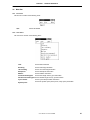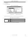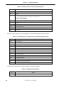
1
查询RX703000供应商
User’s Manual
RD850
Task Debugger (Windows™ Based)
Target Devices
V850 Family™
Target Real-Time OS
RX850 Ver. 3.13
Target Task Debugger
RD850 Ver. 3.01
Document No. U13737EJ2V0UM00 (2nd edition)
Date Published June 2000 N CP(K)
©
Printed in Japan
1998, 2000
[MEMO]
2
User’s Manual U13737EJ2V0UM00
V800 Series, V850 Family, V851, V852, V853, V854, V850/SA1, V850/SB1, V850/SB2, V850/SV1, V850E/MS1,
V850E/MA1, and V850E/IA1 are trademarks of NEC Corporation.
UNIX is a registered trademark in the United States and other countries, licensed exclusively through X/Open
Company Limited.
Windows and Windows NT are either registered trademarks or trademarks of Microsoft Corporation in the
United States and/or other countries.
Pentium is a trademark of Intel Corporation.
Green Hills Software is a trademark of Green Hills Software, Inc.
User’s Manual U13737EJ2V0UM00
3
The export of this product from Japan is regulated by the Japanese government. To export this product may be prohibited
without governmental license, the need for which must be judged by the customer. The export or re-export of this product
from a country other than Japan may also be prohibited without a license from that country. Please call an NEC sales
representative.
• The information in this document is current as of June, 2000. The information is subject to change
without notice. For actual design-in, refer to the latest publications of NEC's data sheets or data
books, etc., for the most up-to-date specifications of NEC semiconductor products. Not all products
and/or types are available in every country. Please check with an NEC sales representative for
availability and additional information.
• No part of this document may be copied or reproduced in any form or by any means without prior
written consent of NEC. NEC assumes no responsibility for any errors that may appear in this document.
• NEC does not assume any liability for infringement of patents, copyrights or other intellectual property rights of
third parties by or arising from the use of NEC semiconductor products listed in this document or any other
liability arising from the use of such products. No license, express, implied or otherwise, is granted under any
patents, copyrights or other intellectual property rights of NEC or others.
• Descriptions of circuits, software and other related information in this document are provided for illustrative
purposes in semiconductor product operation and application examples. The incorporation of these
circuits, software and information in the design of customer's equipment shall be done under the full
responsibility of customer. NEC assumes no responsibility for any losses incurred by customers or third
parties arising from the use of these circuits, software and information.
• While NEC endeavours to enhance the quality, reliability and safety of NEC semiconductor products, customers
agree and acknowledge that the possibility of defects thereof cannot be eliminated entirely. To minimize
risks of damage to property or injury (including death) to persons arising from defects in NEC
semiconductor products, customers must incorporate sufficient safety measures in their design, such as
redundancy, fire-containment, and anti-failure features.
• NEC semiconductor products are classified into the following three quality grades:
"Standard", "Special" and "Specific". The "Specific" quality grade applies only to semiconductor products
developed based on a customer-designated "quality assurance program" for a specific application. The
recommended applications of a semiconductor product depend on its quality grade, as indicated below.
Customers must check the quality grade of each semiconductor product before using it in a particular
application.
"Standard": Computers, office equipment, communications equipment, test and measurement equipment, audio
and visual equipment, home electronic appliances, machine tools, personal electronic equipment
and industrial robots
"Special": Transportation equipment (automobiles, trains, ships, etc.), traffic control systems, anti-disaster
systems, anti-crime systems, safety equipment and medical equipment (not specifically designed
for life support)
"Specific": Aircraft, aerospace equipment, submersible repeaters, nuclear reactor control systems, life
support systems and medical equipment for life support, etc.
The quality grade of NEC semiconductor products is "Standard" unless otherwise expressly specified in NEC's
data sheets or data books, etc. If customers wish to use NEC semiconductor products in applications not
intended by NEC, they must contact an NEC sales representative in advance to determine NEC's willingness
to support a given application.
(Note)
(1) "NEC" as used in this statement means NEC Corporation and also includes its majority-owned subsidiaries.
(2) "NEC semiconductor products" means any semiconductor product developed or manufactured by or for
NEC (as defined above).
M8E 00. 4
4
User’s Manual U13737EJ2V0UM00
Regional Information
Some information contained in this document may vary from country to country. Before using any NEC
product in your application, pIease contact the NEC office in your country to obtain a list of authorized
representatives and distributors. They will verify:
•
Device availability
•
Ordering information
•
Product release schedule
•
Availability of related technical literature
•
Development environment specifications (for example, specifications for third-party tools and
components, host computers, power plugs, AC supply voltages, and so forth)
•
Network requirements
In addition, trademarks, registered trademarks, export restrictions, and other legal issues may also vary
from country to country.
NEC Electronics Inc. (U.S.)
NEC Electronics (Germany) GmbH
NEC Electronics Hong Kong Ltd.
Santa Clara, California
Tel: 408-588-6000
800-366-9782
Fax: 408-588-6130
800-729-9288
Benelux Office
Eindhoven, The Netherlands
Tel: 040-2445845
Fax: 040-2444580
Hong Kong
Tel: 2886-9318
Fax: 2886-9022/9044
NEC Electronics (France) S.A.
Velizy-Villacoublay, France
Tel: 01-30-67 58 00
Fax: 01-30-67 58 99
Seoul Branch
Seoul, Korea
Tel: 02-528-0303
Fax: 02-528-4411
NEC Electronics (France) S.A.
NEC Electronics Singapore Pte. Ltd.
Milton Keynes, UK
Tel: 01908-691-133
Fax: 01908-670-290
Spain Office
Madrid, Spain
Tel: 91-504-2787
Fax: 91-504-2860
United Square, Singapore 1130
Tel: 65-253-8311
Fax: 65-250-3583
NEC Electronics Italiana s.r.l.
NEC Electronics (Germany) GmbH
Milano, Italy
Tel: 02-66 75 41
Fax: 02-66 75 42 99
Scandinavia Office
Taeby, Sweden
Tel: 08-63 80 820
Fax: 08-63 80 388
NEC Electronics (Germany) GmbH
Duesseldorf, Germany
Tel: 0211-65 03 02
Fax: 0211-65 03 490
NEC Electronics (UK) Ltd.
NEC Electronics Hong Kong Ltd.
NEC Electronics Taiwan Ltd.
Taipei, Taiwan
Tel: 02-2719-2377
Fax: 02-2719-5951
NEC do Brasil S.A.
Electron Devices Division
Rodovia Presidente Dutra, Km 214
07210-902-Guarulhos-SP Brasil
Tel: 55-11-6465-6810
Fax: 55-11-6465-6829
J99.1
User’s Manual U13737EJ2V0UM00
5
Major Revisions in This Edition
Page
Description
p.14
Addition of supported host machine OS in 1.3 Operating Environment
p.15
Modification of explanation in 2.1 Installation
p.15
Modification of explanation in 2.2 Directory Configuration
p.45
Addition of APPENDIX B REVISION HISTORY
The mark
6
shows major revised points.
User’s Manual U13737EJ2V0UM00
INTRODUCTION
Target readers
This manual is intended for users who design and develop application systems using
V850 Family products.
Purpose
This manual describes the functions of the RD850, following the organization listed
below.
Organization
This manual consists of the following major sections.
• General
• Installation and startup method
• Window reference
• Error messages
• Cautions
How to read this manual
It is assumed that the readers of this manual have general knowledge in the fields of
electrical engineering, logic circuits, microcontrollers, C language, and assemblers.
To understand the hardware functions of the V850 Family
→ Refer to the User’s Manual Hardware of each product.
To understand the instruction functions of the V850 Family
→ Refer to the V850 Family User’s Manual Architecture (U10243E).
Conventions
Data significance:
Higher digits on the left and lower digits on the right
Note:
Footnote for item marked with Note in the text
Caution:
Information requiring particular attention
Remark:
Supplementary information
Numeric representation:
Binary...XXXX or XXXXB
Decimal...XXXX
Hexadecimal...0xXXXX
Prefixes indicating power of 2 (address space, memory capacity):
K (kilo)
210 = 1024
M (mega)
220 = 10242
User’s Manual U13737EJ2V0UM00
7
Related Documents
Read this manual together with the following documents.
The related documents indicated in this publication may include preliminary versions.
However, preliminary versions are not marked as such.
Documents related to development tools (user’s manuals)
Document Name
TM
TM
TM
Document
Number
TM
TM
TM
IE-703002-MC (In-circuit emulator for V851 , V852 , V853 , V854 , V850/SA1 , V850/SB1 ,
TM
TM
V850/SB2 , V850/SV1 )
U11595E
IE-703003-MC-EM1 (Peripheral I/O board for V853)
U11596E
IE-703008-MC-EM1 (Peripheral I/O board for V854)
U12420E
IE-703017-MC-EM1 (Peripheral I/O board for V850/SA1)
U12898E
IE-703037-MC-EM1 (Peripheral I/O board for V850/SB1, V850/SB2)
U14151E
IE-703040-MC-EM1 (Peripheral I/O board for V850/SV1)
U14337E
TM
IE-703102-MC (In-circuit emulator for V850E/MS1 )
U13875E
IE-703102-MC-EM1, IE-703102-MC-EM1-A (Peripheral I/O board for V850E/MS1)
U13876E
TM
IE-V850E-MC (In-circuit emulator for V850E/IA1 ), IE-V850E-MC-A (In-circuit emulator for V850E1
TM
(NB85E core), V850E/MA1 )
U14487E
IE-V850E-MC-EM1-A (Peripheral I/O board for V850E1(NB85E core))
To be prepared
IE-850E-MC-EM1-B, IE-V850E-MC-MM2 (Peripheral I/O board for V850E1(NB85E core))
U14482E
IE-703107-MC-EM1 (Peripheral I/O board for V850E/MA1)
U14481E
IE-703116-MC-EM1 (Peripheral I/O board for V850E/IA1)
To be prepared
TM
V800 Series Development Tool Application Note Tutorial Guide Windows Based
U14218E
CA850 (C Compiler Package)
Operation Windows Based
U14568E
C Language
U14566E
Project Manager
U14569E
Assembly Language
U14567E
ID850 (Ver. 1.31) (Integrated Debugger)
Operation Windows Based
U14580E
SM850 (Ver. 2.20) (System Simulator)
Operation Windows Based
U14782E
RX850 (Real-Time OS)
Basics
U13430E
Installation
U13410E
Technical
U13431E
Fundamental
U13773E
Installation
U13774E
Technical
U13772E
RX850 Pro (Real-Time OS)
8
RD850 (Task Debugger)
This manual
RD850 Pro (Task Debugger)
U13916E
AZ850 (System Performance Analyzer)
U14410E
PG-FP3 (Flash Memory Programmer)
U13502E
User’s Manual U13737EJ2V0UM00
CONTENTS
CHAPTER 1
GENERAL ...........................................................................................................................13
1.1
Functional Outline......................................................................................................................................... 13
1.2
System Configuration................................................................................................................................... 13
1.3
Operating Environment ................................................................................................................................ 14
1.4
Input Format .................................................................................................................................................. 14
1.5
1.4.1
Numerical values................................................................................................................................. 14
1.4.2
Symbols .............................................................................................................................................. 14
Symbol Display ............................................................................................................................................. 14
CHAPTER 2
INSTALLATION AND STARTUP .......................................................................................15
2.1
Installation ..................................................................................................................................................... 15
2.2
Directory Configuration................................................................................................................................ 15
2.3
Starting the Debugger .................................................................................................................................. 16
CHAPTER 3
WINDOW REFERENCE.....................................................................................................17
3.1
List Display .................................................................................................................................................... 18
3.2
Detailed Display ............................................................................................................................................ 19
3.3
Display Fixing................................................................................................................................................ 19
3.4
Title Bar.......................................................................................................................................................... 20
3.5
Selection Buttons.......................................................................................................................................... 20
3.6
Menu Bar........................................................................................................................................................ 21
3.7
3.8
3.6.1
File menu ............................................................................................................................................ 21
3.6.2
View menu .......................................................................................................................................... 21
3.6.3
Help menu........................................................................................................................................... 22
Task Window ................................................................................................................................................. 23
3.7.1
Task information display ..................................................................................................................... 23
3.7.2
Task source display ............................................................................................................................ 25
Event Flag Window ....................................................................................................................................... 26
3.8.1
3.9
Event flag information display ............................................................................................................. 26
1-Bit Event Flag Window .............................................................................................................................. 27
3.9.1
1-bit event flag information display...................................................................................................... 27
3.10 Semaphore Window...................................................................................................................................... 28
3.10.1 Semaphore information display........................................................................................................... 28
3.11 Mailbox Window ............................................................................................................................................ 29
3.11.1 Mailbox information display ................................................................................................................. 29
3.11.2 Message memory display.................................................................................................................... 30
3.12 Fixed Length Memory Pool Window............................................................................................................ 31
3.12.1 Fixed Length Memory Pool Information Display.................................................................................. 31
3.13 Variable Length Memory Pool Window ....................................................................................................... 32
3.13.1 Variable length memory pool information display................................................................................ 32
3.14 Cyclic Startup Handler Window ................................................................................................................... 34
3.14.1 Cyclic startup handler information display ........................................................................................... 34
3.14.2 Cyclic startup handler source display.................................................................................................. 35
3.15 System Queue Window ................................................................................................................................ 36
3.15.1 System queue information display....................................................................................................... 36
User’s Manual U13737EJ2V0UM00
9
CHAPTER 4
ERROR MESSAGES ........................................................................................................ 39
CHAPTER 5
CAUTIONS ......................................................................................................................... 41
5.1
Next-Step Execution ..................................................................................................................................... 41
5.2
Reserved Words ............................................................................................................................................ 41
5.2.1
RX definition symbols .......................................................................................................................... 41
5.2.2
Cautions on program creation for RD850 users .................................................................................. 41
APPENDIX A INDEX ................................................................................................................................. 43
APPENDIX B REVISION HISTORY ......................................................................................................... 45
10
User’s Manual U13737EJ2V0UM00
LIST OF FIGURES
Figure No.
1-1
Title
Page
RD850 System Configuration ......................................................................................................................... 13
3-1
Resource Information Display Window ........................................................................................................... 17
3-2
Example of Resource Information Display Window Display ........................................................................... 18
3-3
Detailed Display .............................................................................................................................................. 19
3-4
Task Information Display ................................................................................................................................ 23
3-5
Event Flag Information Display ....................................................................................................................... 26
3-6
1-Bit Event Flag Information Display............................................................................................................... 27
3-7
Semaphore Information Display...................................................................................................................... 28
3-8
Mailbox Information Display ............................................................................................................................ 29
3-9
Fixed Length Memory Pool Information Display ............................................................................................. 31
3-10
Variable Length Memory Pool Detailed Display.............................................................................................. 32
3-11
Cyclic Startup Handler Information Display..................................................................................................... 34
3-12
System Queue Information Display................................................................................................................. 36
User’s Manual U13737EJ2V0UM00
11
LIST OF TABLES
Table No.
Title
Page
3-1
Description of Selection Buttons ........................................................................................................................ 20
3-2
Display Contents of List Display Area................................................................................................................ 23
3-3
Display Contents of Task Detailed Display Area ............................................................................................... 24
3-4
Tasks Displayed in List Display Area and Task Detailed Display Area ........................................................ ..... 24
3-5
Additional Task Information ............................................................................................................................... 24
3-6
Display Contents of List Display Area................................................................................................................ 26
3-7
Display Contents of Event Flag Detailed Display Area ...................................................................................... 26
3-8
Display of Event Flag Wait Tasks ...................................................................................................................... 26
3-9
Display Contents of List Display Area................................................................................................................ 27
3-10 Display Contents of 1-Bit Event Flag Detailed Display Area.............................................................................. 27
3-11 Display of 1-Bit Event Flag Wait Task................................................................................................................ 27
3-12 Display Contents of List Display Area................................................................................................................ 28
3-13 Display Contents of Semaphore Detailed Display Area..................................................................................... 28
3-14 Semaphore Wait Task Display........................................................................................................................... 28
3-15 Display Contents of List Display Area................................................................................................................ 30
3-16 Display Contents of Mailbox Detailed Display Area ........................................................................................... 30
3-17 Message Wait Task Display............................................................................................................................... 30
3-18 Information when Messages Exist ..................................................................................................................... 30
3-19 Display Contents of List Display Area................................................................................................................ 31
3-20 Display Contents of Fixed Length Memory Pool Detailed Display Area ............................................................ 31
3-21 Memory Block Wait Task Display....................................................................................................................... 31
3-22 Display Contents of List Display Area................................................................................................................ 32
3-23 Display Contents of Variable Length Memory Pool Detailed Display Area ........................................................ 32
3-24 Memory Block Wait Task Display....................................................................................................................... 33
3-25 Display Contents of List Display Area................................................................................................................ 34
3-26 Display Contents of Cyclic Startup Handler Detailed Display Area.................................................................... 34
3-27 Activation Statuses of List Display Area and Cyclic Startup Handler Detailed Display Area ............................. 35
3-28 Display Contents of List Display Area................................................................................................................ 37
3-29 Display Contents of System Queue Detailed Display Area (Timer Queue Display) .......................................... 37
3-30 Display Contents of System Queue Detailed Display Area (Ready Queue Display) ......................................... 37
12
User’s Manual U13737EJ2V0UM00
CHAPTER 1
GENERAL
1.1 Functional Outline
Note 1
The RD850 consists of a debugger and TIP
, and provides powerful debugging functions for applications that
use the RX850.
The RD850 provides the following functions.
• RTOS
Note 2
resource display function
• RTOS status change function
Notes 1.
2.
TIP: Tool Interface Protocol
RTOS: Real-Time Operating System
1.2 System Configuration
The RD850 consists of a debugger and TIP, which extends the debugger functions.
The system configuration of the RD850 is as follows.
Figure 1-1. RD850 System Configuration
Compiler
Debugger
RX850
RD850
Simulator
Target
IE, ROM monitor, etc.
User’s Manual U13737EJ2V0UM00
13
CHAPTER 1
GENERAL
1.3 Operating Environment
A debugger environment is required to use the RD850. The operating environment of the RD850 is described
below.
• Host Machine
CPU:
Pentium™ 100 MHz or faster
Memory:
32 MB or more
OS:
Windows 95, Windows 98, or Windows NT™ 4.0
• Software
Compiler:
CA850 (from NEC)
CCV850 (from Green Hills Software™, Inc.)
Debugger: TIP-compatible debugger
SM850, etc.
1.4 Input Format
1.4.1 Numerical values
Octal numbers, decimal numbers, and hexadecimal numbers can be input.
Octal:
0 [0-7] +
Hexadecimal: 0 [xX] [0-9a-fA-F] +
Decimal:
Other than above
The range of numerical values that can be input is as follows.
Octal:
0 ≤ Numerical value ≤ 037777777777
Hexadecimal: 0x0 ≤ Numerical value ≤ 0xffffffff
Decimal:
-2147483648 ≤ Numerical value ≤ 4294967295
1.4.2 Symbols
Global symbols of assembly language level are used. Usable characters depend on the language processing
system.
1.5 Symbol Display
Entry address symbols are displayed as Detailed Display area task and cyclic startup handler symbols, but if
symbols do not exist, the entry address is display in hexadecimal notation.
14
User’s Manual U13737EJ2V0UM00
CHAPTER 2
2.1
INSTALLATION AND STARTUP
Installation
This section describes the RD850's installation procedure.
(1) Start up Windows.
(2) Start up the installation program in the RD850's release media. Use either of the following installation
programs.
Japanese: setup_j.exe
English: setup_e.exe
(3) Perform the setup procedure by following the messages displayed on the screen.
2.2
Directory Configuration
After installing the RD850, the configuration of the directory related to the RD850 is as follows.
Install directory
bin
… Execution file (wishtip.exe, rd850.tcl, etc.)
hlp
… Help file
lib
windows
tcl7.6
… Tcl7.6 library
tk4.2
… Tk4.2 library
… TIP library
tipxdbg.dll
RD850 TIP processing library
tipdbg.dll
Debugger TIP processing library
tipcmm.dll
TIP processing common library
Tcl/Tk library
tcl76.dll
tcl1676.dll
tcltip76.dll
tk42.dll
Because the RD850 is included in the RX850 object release package, the RX850 installer is used for installation.
For the details of the installation procedure, refer to RX850 User’s Manual Installation (U13410E).
User’s Manual U13737EJ2V0UM00
15
CHAPTER 2
2.3
INSTALLATION AND STARTUP
Starting the Debugger
The RD850 is described using the Tcl/Tk script language. Therefore, the RD850 itself is not an execution file.
Moreover, since the RD850 operates while communicating with the debugger, it requires a Tcl/Tk that includes a
communication mechanism. This expanded Tcl/Tk is called wishtip (file name:wishtip.exe). The RD850 is interpreted
and executed using wishtip.
There are two methods to start up the RD850.
(1) Startup using startup parameter of wishtip
(2) Double clicking icon after linking with wishtip
The operation is the same with either of these startup methods, but method (2) is recommended because it is the
simpler of the two. For the linking method, see the Windows manual.
16
User’s Manual U13737EJ2V0UM00
CHAPTER 3
WINDOW REFERENCE
The RD850 is started up with the startup methods described in section 2.3 Starting the Debugger.
However, it cannot be used just on its own. The RD850 operates by collecting information via the debugger, so it
must operate at the same time as the debugger. For the operation of the debugger, refer to the ID850 (Ver. 2.20)
Integrated Debugger User's Manual Operation (Windows Based) (U14580E).
When the RD850 starts up, the following window appears.
Figure 3-1. Resource Information Display Window
Title bar
Menu bar
Selection
buttons
HLD check box
List display area
Detailed display area
At this time, the RTOS resource information, etc., is not displayed.
User’s Manual U13737EJ2V0UM00
17
CHAPTER 3
3.1
WINDOW REFERENCE
List Display
To display resource information, click the buttons lined up on the left side of the window.
There are nine buttons lined up vertically. By pressing them, it is possible to display tasks, event flags, 1-bit event
flags, semaphores, the mailbox, fixed length memory pool, variable length memory pool, cyclic startup handler, and
system queue information.
However, the following conditions are required to display this information.
(1) The application linking the RX850 to the debugger must be loaded.
(2) OS initialization must complete.
Remark
(2) is no problem if control is transferred to the task that operates first.
The operation is not guaranteed if selection buttons are pressed while these conditions are not satisfied.
A task information example is shown below.
Figure 3-2. Example of Resource Information Display Window Display
A list of the resources corresponding to the pressed button is displayed as shown in Figure 3-2.
18
User’s Manual U13737EJ2V0UM00
CHAPTER 3
3.2
WINDOW REFERENCE
Detailed Display
At the debug stage, resource lists are required, as is detailed resource information. In this case, click the resource
for which you want to display detailed information. When a resource is clicked, the detailed information for that
resource is displayed in the right area of the window.
Figure 3-3. Detailed Display
Figure 3-3 shows an example of tasks, but the operation is the same for all other resources.
3.3
Display Fixing
The HLD check box at the lower left corner of the window is a switch that fixes the status currently displayed.
Normally, it is OFF.
When the HLD check box is set to ON, the display information is not updated until the check box is set to OFF
again, regardless of whether program execution or breaks occur thereafter. By using this function, statuses at
different times can easily be compared by starting up several RD850.
User’s Manual U13737EJ2V0UM00
19
CHAPTER 3
3.4
WINDOW REFERENCE
Title Bar
The title bar shows the type of resource currently selected. The title format is as follows.
RD850 [Resource Type]
3.5
Selection Buttons
The RD850 has the following buttons.
Table 3-1. Description of Selection Buttons
Button
Description
Shows task information
Shows event flag information
Shows 1-bit event flag information
Shows semaphore information
Shows mailbox information
Shows fixed length memory pool information
Shows variable length memory pool information
Shows cyclic startup handler information
Shows system queue (timer queue, ready queue)
Switches between Hold/Active.
20
User’s Manual U13737EJ2V0UM00
CHAPTER 3
3.6
WINDOW REFERENCE
Menu Bar
3.6.1 File menu
The file menu consists of the following items.
Quit
Closes the RD850.
3.6.2 View menu
The view menu consists of the following items.
Task
Shows task information
Eventflag
Shows event flag information
1bit eventflag
Shows 1-bit event flag information
Semaphore
Shows semaphore information
Mailbox
Shows mailbox information
Fixed-size memorypool
Shows fixed length memory pool information
Variable-size memorypool Shows variable length memory pool information
Cyclic handler
Shows cyclic startup handler information
System queue
Shows the system queue (timer queue, ready queue) information
User’s Manual U13737EJ2V0UM00
21
CHAPTER 3
WINDOW REFERENCE
3.6.3 Help menu
The help menu consists of the following items.
22
Contents
Opens the help file
About RD850
Shows the RD850 version information
User’s Manual U13737EJ2V0UM00
CHAPTER 3
3.7
WINDOW REFERENCE
Task Window
3.7.1 Task information display
Figure 3-4. Task Information Display
List display area
Task detailed display area
Tables 3-2 to 3-5 show the information shown in the list display area and the task detailed display area.
Table 3-2. Display Contents of List Display Area
Item
List display area
Remark
Contents
1st item
Task name
2nd item
Current task priority (displays "—" when the task status is DMT, WTX, WTX | SUS)
3rd item
Task status
Tasks are shown in the order of the ID number in the list display area.
User’s Manual U13737EJ2V0UM00
23
CHAPTER 3
WINDOW REFERENCE
Table 3-3. Display Contents of Task Detailed Display Area
Label
Contents
name
Task name
tskid
Task ID
entry
Task start address
If there is debug information: File name # line number (symbol)
If there is a symbol: Symbol
If there is no symbol: Address
sts
Status
pri
Priority
suscnt
Suspend count
wupcnt
Startup request count
pc
Current PC
stkptr
Stack pointer
The statuses of the tasks shown in the list display area and task detailed display area are as follows.
Table 3-4. Tasks Displayed in List Display Area and Task Detailed Display Area
Display
Meaning
RUN
Execution status
RDY
Execution enabled status
DMT
Halt status
SUS
Suspend status
WTX
Task execution right wait status
SLP
Startup wait status
DLY
Time limit wait status
EVF
Event flag wait status
1EF
1-bit event flag wait status
SEM
Semaphore wait status
MBX
Message wait status
MPF
Fixed length memory block wait status
MPL
Variable length memory block wait status
If the task is in the wait status, information additional to the status is displayed.
Table 3-5. Additional Task Information
Display
TIM
24
Meaning
Wait status with time limit
User’s Manual U13737EJ2V0UM00
CHAPTER 3
WINDOW REFERENCE
There may be several of the above-described task statuses. In this case, these statuses are displayed separated
by "|".
Moreover, if tasks have resources (event flag, 1-bit event flag, semaphore, mailbox, fixed length memory pool,
variable length memory pool), the names of these resources are displayed in addition to the status.
3.7.2 Task source display
By double clicking the entry and pc lines in the task detailed display area, the Source window of the debugger is
opened if there is debug information, and the Assembler window of the debugger is opened if there is no debug
information.
User’s Manual U13737EJ2V0UM00
25
CHAPTER 3
3.8
WINDOW REFERENCE
Event Flag Window
3.8.1 Event flag information display
Figure 3-5. Event Flag Information Display
List display area
Event flag detailed display area
Tables 3-6 to 3-8 show the information displayed in the list display area and event flag detailed display area.
Table 3-6. Display Contents of List Display Area
Item
List display area
Contents
1st item
Event flag name
2nd item
Existence of wait task (TSK: Wait task, NON: No wait task)
3rd item
Current bit pattern
Table 3-7. Display Contents of Event Flag Detailed Display Area
Label
Contents
name
Event flag name
evfid
Event flag ID
pattern
Current bit pattern
If a task with an event flag exists, the following information is displayed.
Table 3-8. Display of Event Flag Wait Tasks
Label
wait tsk
26
Contents
Wait task name
ptn
Wait pattern
opt
Wait option (TWF_ORW: OR wait, TWF_ANDW: AND wait)
clr
Existence of clear specification (ON: Clear specification, OFF: No clear specification)
User’s Manual U13737EJ2V0UM00
CHAPTER 3
3.9
WINDOW REFERENCE
1-Bit Event Flag Window
3.9.1 1-bit event flag information display
Figure 3-6. 1-Bit Event Flag Information Display
List display area
1-bit event flag detailed display area
Tables 3-9 to 3-11 show the information displayed in the list display area and 1-bit event flag detailed display area.
Table 3-9. Display Contents of List Display Area
Item
List display area
Contents
1st item
1-bit event flag name
2nd item
Existence of wait task (TSK: Wait task, NON: No wait task)
3rd item
Current bit pattern
Table 3-10. Display Contents of 1-Bit Event Flag Detailed Display Area
Label
Contents
name
1-bit event flag name
evfid
1-bit event flag ID
bit
Current bit
If there is a task that waits for a 1-bit event flag, the following information is displayed.
Table 3-11. Display of 1-Bit Event Flag Wait Task
Label
wait tsk
Contents
Wait task name
clr
Existence of clear specification (ON: Clear specification, OFF: No clear specification)
User’s Manual U13737EJ2V0UM00
27
CHAPTER 3
WINDOW REFERENCE
3.10 Semaphore Window
3.10.1 Semaphore information display
Figure 3-7. Semaphore Information Display
List display area
Semaphore detailed display area
Tables 3-12 to 3-14 show the information displayed in the list display area and semaphore display area.
Table 3-12. Display Contents of List Display Area
Item
List display area
Contents
1st item
Semaphore name
2nd item
Existence of wait task (TSK: Wait task, NON: No wait task)
3rd item
Current resource count
Table 3-13. Display Contents of Semaphore Detailed Display Area
Label
Contents
name
Semaphore name
semid
Semaphore ID
count
Current resource count
If there is a task that waits for a semaphore, the following information is displayed.
Table 3-14. Semaphore Wait Task Display
Label
wait tsk
28
Contents
Wait task name
User’s Manual U13737EJ2V0UM00
CHAPTER 3
3.11
WINDOW REFERENCE
Mailbox Window
3.11.1 Mailbox information display
Figure 3-8. Mailbox Information Display
List display area
Mailbox detailed display area
Tables 3-15 to 3-18 show the information displayed in the list display area and mailbox detailed display area.
User’s Manual U13737EJ2V0UM00
29
CHAPTER 3
WINDOW REFERENCE
Table 3-15. Display Contents of List Display Area
Item
List display area
Contents
1st item
Mailbox name
2nd item
Existence of wait task (TKS: Wait task, MSG: Receive wait message, NON: No wait
task, no receive wait message)
Table 3-16. Display Contents of Mailbox Detailed Display Area
Label
Contents
name
Mailbox name
mbxid
Mailbox ID
mopt
Message queuing format (TA_MFIFO: FIFO order/TA_MPRI: Priority order)
If a task waiting for a message exists, the following information is displayed.
Table 3-17. Message Wait Task Display
Label
wait tsk
Contents
Wait task name
If a message exists, the following information is displayed.
Table 3-18. Information when Messages Exist
Label
message
Contents
Message address
3.11.2 Message memory display
The debugger's Memory window can be opened by double clicking the message line of the mailbox detailed
display area.
30
User’s Manual U13737EJ2V0UM00
CHAPTER 3
WINDOW REFERENCE
3.12 Fixed Length Memory Pool Window
3.12.1 Fixed Length Memory Pool Information Display
Figure 3-9. Fixed Length Memory Pool Information Display
List display area
Fixed length memory pool detailed display area
Tables 3-19 to 3-21 show the information displayed in the list display area and fixed length memory pool detailed
display area.
Table 3-19. Display Contents of List Display Area
Item
List display area
Contents
1st item
Fixed length memory pool name
2nd item
Existence of wait task (TSK: Wait task, NON: No wait task)
Table 3-20. Display Contents of Fixed Length Memory Pool Detailed Display Area
Label
Contents
name
Fixed length memory pool name
mpfid
Fixed length memory pool ID
free blk
Free memory block count
If there is a task that waits for a memory block, the following information is displayed.
Table 3-21. Memory Block Wait Task Display
Label
wait tsk
Contents
Wait task name
User’s Manual U13737EJ2V0UM00
31
CHAPTER 3
WINDOW REFERENCE
3.13 Variable Length Memory Pool Window
3.13.1 Variable length memory pool information display
Figure 3-10. Variable Length Memory Pool Detailed Display
List display area
Variable length memory pool detailed display area
Tables 3-22 to 3-24 show the information displayed in the list display area and variable length memory pool
detailed display area.
Table 3-22. Display Contents of List Display Area
Item
List display area
Contents
1st item
Variable length memory pool name
2nd item
Existence of wait task (TSK: Wait task, NON: No wait task)
Table 3-23. Display Contents of Variable Length Memory Pool Detailed Display Area
Label
Contents
name
Variable length memory pool name
mplid
Variable length memory pool ID
topadr
Memory pool start address
size
Memory pool size (Unit: byte)
free
Total free memory size (Unit: byte)
max
Maximum securable memory block size (Unit: byte)
If there is a task that waits for a memory block, the following information is displayed.
32
User’s Manual U13737EJ2V0UM00
CHAPTER 3
WINDOW REFERENCE
Table 3-24. Memory Block Wait Task Display
Label
wait tsk
Contents
Wait task name
size
Wait block size (Unit: byte)
(The value that is the result of adding the 4 bytes required by the OS is displayed
upon request with a system call)
User’s Manual U13737EJ2V0UM00
33
CHAPTER 3
WINDOW REFERENCE
3.14 Cyclic Startup Handler Window
3.14.1 Cyclic startup handler information display
Figure 3-11. Cyclic Startup Handler Information Display
List display area
Cyclic startup handler detailed display area
Tables 3-25 to 3-27 show the information displayed in the list display area and cyclic startup handler detailed
display area.
Table 3-25. Display Contents of List Display Area
Item
List display area
Contents
1st item
Cyclic startup handler name
2nd item
Activation status (TCY_ON, TCY_OFF, TCY_ULNK)
Table 3-26. Display Contents of Cyclic Startup Handler Detailed Display Area
Label
34
Contents
name
Cyclic startup handler name
cycno
Cyclic startup handler number
entry
Cyclic startup handler start address
If there is debug information: File name # line number (symbol)
If there is a symbol: Symbol
If there is no symbol: Address
intvl
Cyclic startup interval
activate
Activation status
User’s Manual U13737EJ2V0UM00
CHAPTER 3
WINDOW REFERENCE
The activation statuses of the list display area and cyclic startup handler detailed display area are as follows.
Table 3-27. Activation Statuses of List Display Area and Cyclic Startup Handler Detailed Display Area
Display
Contents
TCY_ON
Started-up status
TCY_OFF
Not started-up status
TCY_ULNK
TCY_OFF status and removed from timer queue
3.14.2 Cyclic startup handler source display
By double clicking the entry line in the cyclic startup handler detailed display area, the Source window of the
debugger is opened if there is debug information, and the Assembler window of the debugger is opened if there is no
debug information.
User’s Manual U13737EJ2V0UM00
35
CHAPTER 3
WINDOW REFERENCE
3.15 System Queue Window
3.15.1 System queue information display
Figure 3-12. System Queue Information Display
List display area
36
System queue detailed display area
User’s Manual U13737EJ2V0UM00
CHAPTER 3
WINDOW REFERENCE
The system queue information display shows the timer queue and ready queue information.
Tables 3-28 to 3-30 show the information displayed in the list display area and system queue detailed display
area.
Table 3-28. Display Contents of List Display Area
Item
List display area
Contents
1st item
System queue name (TimerQueue/ReadyQueue)
2nd item
Priority (None in the case of timer queue)
Table 3-29. Display Contents of System Queue Detailed Display Area (Timer Queue Display)
Label
None
Contents
Cyclic startup handler name/task name wait block count
Table 3-30. Display Contents of System Queue Detailed Display Area (Ready Queue Display)
Label
task
Contents
Task name
User’s Manual U13737EJ2V0UM00
37
[MEMO]
38
User’s Manual U13737EJ2V0UM00
CHAPTER 4
ERROR MESSAGES
The description of error messages is done in the following format.
Error No.
The error number.
Error message
Message that is output
Error contents
The contents of the message that is output
The error messages are listed below.
Error No.
1000
Error message
Not connect.
Error contents
Displayed when the debugger is not connected. Start up the debugger.
Error No.
1100
Error message
Debugger running.
Error contents
Displayed when the display resources are changed or a status is changed when the status is
not the break status. Operation when in the break status.
Error No.
1200
Error message
Maybe RX not loaded..
Error contents
RX is not loaded. Load RX.
Error No.
1300
Error message
Interrupt Disabled.
Error contents
The status cannot be changed because the system is in the interrupt disabled status. Retry
after setting the interrupt enable status.
User’s Manual U13737EJ2V0UM00
39
[MEMO]
40
User’s Manual U13737EJ2V0UM00
CHAPTER 5
CAUTIONS
This chapter describes cautions that apply to debugging a load module incorporating the RX850, using the ID850
integrated debugger (including the RD850).
5.1
Next-Step Execution
When debugging a load module that incorporates the RX850, observe sthe following three points when executing
the next step.
(1) Do not next-step execute the ext_tsk.
Tasks which are next-step executed (hereafter known as target tasks) simply terminate, and no break occurs.
Even if a break occurs, it may occur during processing after sta_tsk is issued for the next target task (or a task
sharing a task with the target task).
Even if no break has occurred, it may occur by selecting "Execute(X) → Stop" or "Execute → Stop" in the
menu bar in the main window.
(2) Be careful with next-step execution of tasks for which ter_tsk can be performed.
If ter_tsk is performed during next-step execution, the target task simply terminates and no break occurs.
Even if a break occurs, it may occur during processing after sta_tsk is issued for the next target task (or a task
sharing a task with the target task).
Even if no break has occurred, a break may occur by selecting "Execute(X) → Stop" or "Execute → Stop" in
the menu bar in the main window.
(3) Next-step execution may not function appropriately during RX processing.
A break may occur inside a subroutine.
5.2
Reserved Words
Symbols reserved by the RX850 and RD850 are listed below.
5.2.1 RX definition symbols
The RX and RX configurators are defined as external symbols, and are referenced by the RD850.
RX850*
Sit*
SysIntEnt
RX system call name
5.2.2 Cautions on program creation for RD850 users
To realize useful debugging functions using the RX850 for the RD850, the RX850 and RD850 have reserved
symbols (see section 5.2.1 RX definition symbols).
Using symbols that have the same name as these reserved symbols will interfere with the debugging functions of
the RD850.
Do not use the reserved symbols of the RX and RD850 in user programs.
User’s Manual U13737EJ2V0UM00
41
[MEMO]
42
User’s Manual U13737EJ2V0UM00
APPENDIX A
INDEX
[A]
Mailbox .......................................................... 18, 29
Activation status .......................................................34
ready queue ........................................................ 37
Semaphore .................................................... 18, 28
[B]
System queue................................................ 18, 36
Bit pattern ...........................................................26, 27
Task............................................................... 18, 23
Timer queue ........................................................ 37
Variable length memory pool......................... 18, 32
[C]
CA850.......................................................................14
RTOS ....................................................................... 13
CCV850 ....................................................................14
RX definition symbol ................................................ 41
RX850 .......................................................... 13, 18, 41
[D]
Directory configuration..............................................15
[S]
Script language ........................................................ 16
[E]
SM850...................................................................... 14
Error messages .......................................................39
Source window......................................................... 35
System call............................................................... 33
[F]
File menu..................................................................21
[T]
task ............................................ 26, 27, 28, 30, 31, 32
[G]
TIP ..................................................................... 13, 15
Global symbols .........................................................14
Title bar .................................................................... 17
[H]
[V]
Help menu ................................................................22
Version information .................................................. 22
HLD check box .........................................................19
View menu ............................................................... 21
[I]
ID850 ..................................................................17, 41
[M]
Memory block ...............................................24, 31, 32
[N]
Next-step execution..................................................41
[R]
RD850 ..........................................................13, 17, 41
Reserved words........................................................41
Resource count ........................................................28
Resource information ...............................................18
Resource information
1-bit event flags..............................................18, 27
Cyclic startup handler ....................................18, 34
Event flag .......................................................18, 26
Fixed length memory pool..............................18, 31
User’s Manual U13737EJ2V0UM00
43
[MEMO]
44
User’s Manual U13737EJ2V0UM00
APPENDIX B REVISION HISTORY
A history of the revisions up to this edition is shown below. “Applied to:” indicates the chapters to which the revision
was applied.
Edition
Second edition
Contents
Applied to:
Addition of target OS to operating environment host machine
CHAPTER 1 GENERAL
Modification of explanation for installation method
CHAPTER 2 INSTALLATION
Modification of explanation for directory configuration
AND STARTUP
Modification of directory configuration diagram
User’s Manual U13737EJ2V0UM00
45
[MEMO]
46
User’s Manual U13737EJ2V0UM00
Facsimile Message
From:
Name
Company
Tel.
Although NEC has taken all possible steps
to ensure that the documentation supplied
to our customers is complete, bug free
and up-to-date, we readily accept that
errors may occur. Despite all the care and
precautions we've taken, you may
encounter problems in the documentation.
Please complete this form whenever
you'd like to report errors or suggest
improvements to us.
FAX
Address
Thank you for your kind support.
North America
Hong Kong, Philippines, Oceania
NEC Electronics Inc.
NEC Electronics Hong Kong Ltd.
Corporate Communications Dept. Fax: +852-2886-9022/9044
Fax: 1-800-729-9288
1-408-588-6130
Korea
Europe
NEC Electronics Hong Kong Ltd.
NEC Electronics (Europe) GmbH
Seoul Branch
Technical Documentation Dept.
Fax: 02-528-4411
Fax: +49-211-6503-274
South America
NEC do Brasil S.A.
Fax: +55-11-6465-6829
Asian Nations except Philippines
NEC Electronics Singapore Pte. Ltd.
Fax: +65-250-3583
Japan
NEC Semiconductor Technical Hotline
Fax: 044-548-7900
Taiwan
NEC Electronics Taiwan Ltd.
Fax: 02-2719-5951
I would like to report the following error/make the following suggestion:
Document title:
Document number:
Page number:
If possible, please fax the referenced page or drawing.
Document Rating
Excellent
Good
Acceptable
Poor
Clarity
Technical Accuracy
Organization
CS 99.1