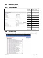
1
AC1200MS
User Manual
Table of Contents
1
2
3
4
5
Preface .......................................................................................................................................................... 1
LED Indicators and Connectors .................................................................................................................... 1
2.1
LED Indicators .............................................................................................................................. 1
2.2
Hardware Installation .................................................................................................................... 2
Voice Prompt................................................................................................................................................. 2
Configuring Basic Settings ........................................................................................................................... 5
4.1
Two-Level Management ............................................................................................................... 5
4.2
Accessing the User Interface Web Page ........................................................................................ 5
4.2.1
From the LAN Port ............................................................................................................... 5
4.2.2
From the WAN Port .............................................................................................................. 5
4.3
Webpage ........................................................................................................................................ 6
4.4
Setting Up the Time Zone ............................................................................................................. 6
4.5
Setting up the Internet Connection................................................................................................ 7
4.5.1
Static IP ................................................................................................................................. 7
4.5.2
DHCP .................................................................................................................................... 7
4.5.3
PPPoE ................................................................................................................................... 8
4.6
Setting up the Wireless Connection .............................................................................................. 8
4.6.1
Enable Wireless and Set the SSID ........................................................................................ 8
4.6.2
Encryption ............................................................................................................................. 9
4.7
Register ......................................................................................................................................... 9
4.7.1
Get a SIP Account ................................................................................................................. 9
4.7.2
Connect ................................................................................................................................. 9
4.7.3
Configure SIP from Webpage ............................................................................................... 9
4.7.4
View the Register Status ..................................................................................................... 10
4.8
Make Call .................................................................................................................................... 10
4.8.1
Calling phone or extension numbers ................................................................................... 10
4.8.2
Direct IP calls ...................................................................................................................... 10
4.8.3
Call Hold ............................................................................................................................. 11
4.8.4
Blind Transfer ..................................................................................................................... 11
4.8.5
Attended Transfer................................................................................................................ 11
4.8.6
Conference .......................................................................................................................... 11
Web Configuration ...................................................................................................................................... 12
5.1
Login ........................................................................................................................................... 12
5.2
Configuring the WAN and LAN Ports ........................................................................................ 12
5.2.1
WAN ................................................................................................................................... 13
5.2.2
LAN .................................................................................................................................... 15
5.2.3
DMZ/Port Forward ............................................................................................................. 16
5.2.4
MAC Clone ......................................................................................................................... 17
5.2.5
Multi WAN.......................................................................................................................... 17
5.3
Wireless ....................................................................................................................................... 18
5.3.1
Basic.................................................................................................................................... 18
6
5.3.2
Wireless Security ................................................................................................................ 18
5.3.3
WMM.................................................................................................................................. 19
5.3.4
WPS .................................................................................................................................... 19
5.3.5
Station list ........................................................................................................................... 20
5.3.6
Advanced ............................................................................................................................ 20
5.3.7
5GHz Access Point ............................................................................................................. 21
5.3.8
Security for 5GHz Access Point.......................................................................................... 22
5.4
SIP Account................................................................................................................................. 23
5.4.1
SIP Settings ......................................................................................................................... 23
5.4.2
Line 1 .................................................................................................................................. 24
5.4.3
VoIP QoS............................................................................................................................. 25
5.5
Phone .......................................................................................................................................... 25
5.5.1
Preferences .......................................................................................................................... 25
5.5.2
Dial Plan.............................................................................................................................. 26
5.5.3
Call Log .............................................................................................................................. 26
5.6
Security ....................................................................................................................................... 27
5.6.1
Filtering Setting .................................................................................................................. 27
5.6.2
DMZ.................................................................................................................................... 27
5.6.3
MAC Clone ......................................................................................................................... 28
5.6.4
Port Forward ....................................................................................................................... 28
5.6.5
Content Filtering ................................................................................................................. 28
5.7
Administration ............................................................................................................................ 29
5.7.1
Management........................................................................................................................ 29
5.8
System Log ................................................................................................................................. 29
5.9
Logout ......................................................................................................................................... 30
5.10
Reboot ......................................................................................................................................... 30
FCC Statement ............................................................................................................................................ 30
1
Preface
Thank you for choosing the ReadyNet AC1200MS wireless router with VoIP. This product will
allow you to make ATA calls using your broadband connection and provides W i-Fi router
functions.
This manual provides basic information on how to install and connect the ReadyNet
AC1200MS wireless router with VoIP to the Internet. It also discusses the router’s features
and functions and how to use them correctly. Before you can connect the AC1200MS to the
Internet and use it, you must have a high-speed broadband connection installed.
The ReadyNet AC1200MS wireless router with VoIP is a stand-alone device so no computer
is required to make Internet calls. The AC1200MS provides clear and reliable voice quality
through the Internet, is fully compatible with SIP industry standards, and is able to
interoperate with many other SIP devices and software on the market.
2
LED Indicators and Connectors
2.1
LED Indicators
Front Panel
LED
POW ER
Status
On (Red)
Off
On (Green)
W AN
Off
Blinking (Green)
On (Green)
LAN
1/2/3/4
2.4G
5G
The router is powered on
and running normally.
The router is powered off.
The port is connected
with 100Mbps.
The port is disconnected.
It will blink while
transmitting data.
The port is connected
with 100Mbps.
Off
The port is disconnected.
Blinking (Green)
The data is transmitting.
On (Green)
Blinking (Green)
On (Green)
USB
Off
Version 1.0
Explanation
Wireless access point is
ready.
It will blink while wireless
traffic goes through.
USB device is connected.
No USB device
connected.
Page |1
Rear Panel
Interface
Description
RST
Reset to factory default settings
WAN
Connector for accessing the Internet.
LAN
(1/2/3/4)
USB
DC
12V/2A
ON/OFF
Connectors for local networked devices.
Connector for USB device.
Connector for a power adapter.
Power Switch.
Hardware Installation
Step 1.Connect the Line port to a land line phone jack with an RJ-11 cable (standard phone
cord).
Step 2.Connect the W AN port to an access point such as a modem, switch, or router with an
Ethernet cable.
Step 3.Connect one of the LAN ports to your computer with an Ethernet cable.
Step 4.Connect one end of the power cord to the power port of this device. Connect the other
end to the wall outlet of electricity.
Step 5.Push the ON/OFF switch to power on the router.
Step 6.Check the Power, W AN, and LAN LEDs to assure network connections.
3
Voice Prompt
Voice Menu Setting Options
Code
Contents
Step 1. Pick up phone and press “****” to start IVR.
Step 2. Choose “1” and the AC1200MS reports the current WAN port connection type.
Step 3. Prompt "Please enter password”, user needs to input password with end char # if user
wants to configure WAN port connection type.
1
Password in the IVR is same as the Web login. User can use phone keypad to enter
password directly and the matching table is in Note 4.
For example: WEB login password is “admin”, so password in IVR is “admin” too, user
inputs “23646” to access and then configure theWAN connection port.
Step 4. Report “operation successful” if password is correct.
Step 5. Choose the new WAN port connection type, either 1. DHCP or 2. Static.
Step 6. Report “operation successful”, indicates user successfully made the changes.
AC1200MS will return to sound prompting “please enter your option, one WAN
Port …….”.
Version 1.0
If at any time you want to quit, press “**”.
Page |2
Step 1. Pick up phone and press “****” to start IVR.
Step 2. Choose “2”, and the AC1200MS reports current WAN Port IP Address.
Step 3. Input the new WAN port IP address with the end char #.
2
Using “*” to replace “.”, user can input 192*168*20*168 to set the new IP address
192.168.20.168.
Press # key to indicate you have finished.
Step 4. Report “operation successful” if user operation is correct.
If at any time you want to quit, press “**”.
Step 1. Pick up phone and press “****” to start IVR.
Step 2. Choose “3”, and the AC1200MS reports the current WAN port subnet mask.
Step 3. Input a new WAN port subnet mask with the end char #.
3
Using “*” to replace “.”, user can input 255*255*255*0 to set the new WAN port subnet mask
255.255.255.0.
Press # key to indicate you have finished.
Step 4. Report “operation successful” if user operation is correct.
If at any time you want to quit, press “**”.
Step 1. Pick up phone and press “****” to start IVR.
Step 2. Choose “4”, and the AC1200MS reports current gateway.
Step 3. Input the new gateway with the end char #.
4
Using “*” to replace “.”, user can input 192*168*20*1 to set the new gateway 192.168.20.1.
Press # key to indicate you have finished.
Step 4. Report “operation successful” if user operation is correct.
If at any time you want to quit, press “**”.
Step 1. Pick up phone and press “****” to start IVR
Step 2. Choose “5”, and the AC1200MS reports current DNS
Step 3. Input the new DNS with the end char #
5
Using “*” to replace “.”, user can input 192*168*20*1 to set the new gateway to
192.168.20.1
Press # key to indicate you have finished
Step 4. Report “operation successful” if user operation is correct.
If at any time you want to quit, press “**”.
Step 1. Pick up phone and press “****” to start IVR.
Step 2. Choose “6”, and the AC1200MS reports “Factory Reset”.
6
Step 3. Prompt "Please enter password", inputting password is the same as in operation 1.
If at any time you want to quit, press “*”.
Step 4. Prompt “operation successful” if the password is correct.
Step 5. Press “7”, reboot to make changes effective.
Step 1. Pick up phone and press “****” to start IVR.
7
Step 2. Choose “7”, and the AC1200MSs report “Reboot”.
Step 3. Prompt "Please enter password", inputting password is the same as in operation 1.
Step 4. The AC1200MS will reboot if the operation is correct.
Version 1.0
Page |3
Step 1. Pick up phone and press “****” to start IVR.
Step 2. Choose “8”, and the AC1200MS reports “WAN Port Login”.
Step 3. Prompt "Please enter password", inputting password is the same as in operation 1.
8
If at any time you want to quit, press “*”.
Step 4. Report “operation successful” if user operation is correct.
Step 5. Prompt “1enable 2disable”,choose 1 or 2 with confirm char #.
Step 6. Report “operation successful” if user operation is correct.
Step 1. Pick up phone and press “****” to start IVR.
Step 2. Choose “9”, and the AC1200MS reports “ WEB Access Port”.
Step 3. Prompt “Please enter password”, inputting password is the same as in operation 1.
Step 4. Report “operation successful” if user operation is correct.
9
Step 5. Report the current WEB Access Port.
Step 6. Set the new WEB access port with end char #.
Step 7. Report “operation successful” if user operation is correct.
Step 1. Pick up phone and press “****” to start IVR.
0
Step 2. Choose “0”, and the AC1200MS reports the current Firmware version.
Notes
W hen using Voice Menu, press “*” (star) to return to the main menu.
If any changes are made in the IP assignment mode, please reboot the AC1200MS to apply the
changes.
W hen entering an IP address or subnet mask, use “*” (star) to replace “.” (dot). For example, to
enter the IP address 192.168.20.159 by keypad, press 192*168*20*159#, use the “#” (pound) key
to indicate you have finished entering the IP address.
W hen assigning an IP address in Static IP mode, you must also set the subnet mask and default
gateway. If in DHCP mode, please make sure that DHCP SERVER is available in your existing
broadband connection to which W AN port of AC1200MS is connected.
The default LAN port IP address of AC1200MS is 192.168.11.1 and do not set the W AN port IP
address of AC1200MS in the same network segment of LAN port of AC1200MS, otherwise it may
lead to the AC1200MS fail to work properly.
Enter the password by phone keypad. The matching table between number and letters is as
follows:
Version 1.0
To input: D, E, F, d, e, f -- press ‘3’
To input: G, H, I, g, h, i -- press ‘4’
To input: J, K, L, j, k, l -- press ‘5’
To input: M, N, O, m, n, o -- press ‘6’
To input: P, Q, R, S, p, q, r, s -- press ‘7’
To input: T, U, V, t, u, v -- press ‘8’
To input: W, X, Y, Z, w, x, y, z -- press ‘9’
To input all other characters in the administrator password-----press ‘0’, e.g. password
is ‘admin-admin’, press ‘23646023646’
Page |4
4
Configuring Basic Settings
4.1
Two-Level Management
The AC1200MS supports user management. For user mode operation, please log in to the
user interface W eb Page. The Username is “user” and the default Password is the last 8
letters of the LAN port MAC address.
This section also explains how to set up a password for an administrator/root user and how to
adjust basic/advanced settings for successfully accessing the Internet.
4.2
Accessing the User Interface Web Page
4.2.1 From the LAN Port
Step1. Connect your computer to one of the router’s LAN ports using an Ethernet cable.
Notice: You may either simply set up your computer to get IP dynamically from the router or
set up the IP address of the computer to be the same subnet as the default IP address
of the router, which is 192.168.11.1.
Step 2. Open a web browser on your computer, type http://192.168.11.1. The following login
window will open.
Step 3. To login, type in the Username and Password found on the label on the bottom of the
AC1200MS and click Login. (The username is “user” and the password is printed on the label
on the bottom of your router.)
The web page will log out after 5 minutes of no activity.
4.2.2 From the WAN Port
By default, remote web login is disabled so user will need to enable remote web login and
change the password through the LAN port before attempting to login from the W AN port.
The remote login port is 8080.
Step 1. Make sure your PC can connect to the router’s W AN port.
Step 2. Get the IP address of the W AN port using Voice Prompt.
Version 1.0
Page |5
Step 3.Open a web browser on your computer and type http://the IP address of WAN port:
8080. The following login window will open.
Step 4.To login, type in the Username and Password found on the label on the bottom of the
AC1200MS and click Login. (The username is “user” and the password is the last 8
characters of the LAN MAC address.)
The web page will log out after 5 minutes of no activity.
4.3
Webpage
No.
1
Name
Description
Navigation
Click navigation bar, sub-navigation
bar
bars will appear on the second line.
2
Title
3
Parameter
Click on the sub-navigation bars to
choose a configuration page.
To configure the parameters.
After every change, click this button to
apply the change.
After clicking Save, the red
will appear.
Click to cancel changes.
Click to reboot the router.
4.4
Setting Up the Time Zone
Open Administration/Management webpage as shown below, select the Time Zone,
specify the NTP server and set the update interval in NTP synchronization.
Version 1.0
Page |6
4.5
Setting up the Internet Connection
Open the Network/WAN webpage as shown below and select the appropriate IP Mode
according to the information from your ISP. There are three types offered – Static, DHCP and
PPPoE.
4.5.1
Static IP
You will receive a fixed public IP address or a public subnet (multiple public IP addresses)
from your DSL or Cable ISP service providers. In most cases, a Cable service provider will
offer a fixed public IP while a DSL service provider will offer a public subnet. If you have a
public subnet, you can assign an IP address to the W AN interface.
IP Address
Subnet Mask
Gateway IP
Address
4.5.2
Type the IP address.
Type the subnet mask.
Type the gateway IP address.
Primary DNS
Type in the primary IP
Server
address for the route.
Secondary
Type in secondary IP address
DNS Server
for necessity in the future.
DHCP
It is not necessary for you to type any IP address manually. Simply choose this type and the
system will obtain the IP address automatically from the DHCP server.
Set the DNS Mode to Auto or Manual. If
DNS Mode
user chooses Manual, fill in the primary
and secondary DNS addresses.
Primary DNS
Server
Version 1.0
Type in the primary IP address for the
route.
Secondary
Type in secondary IP address for
DNS Server
necessity in the future.
Page |7
4.5.3
PPPoE
PPPoE stands for Point-to-Point Protocol over Ethernet. It relies on two widely accepted
standards: PPP and Ethernet. It connects users through an Ethernet to the Internet with a
common broadband medium, such as a single DSL line, wireless device, or cable modem. All
users over the Ethernet can share a common connection.
PPPoE is often used for DSL. All local users can share one PPPoE connection for accessing
the Internet. Your service provider will provide you information about user name, password,
and authentication mode.
PPPoE
Account
PPPoE
Password
Confirm
Password
Assign a specific valid user name
provided by the ISP.
Assign a valid password provided by
the ISP.
Input the password again.
Set the DNS Mode to Auto or
DNS Mode
Manual.
If Manual, fill in primary and
secondary DNS addresses.
Primary
4.6
Type in the primary IP address for
DNS Server
the route.
Secondary
Type in secondary IP address for
DNS Server
necessity in the future.
Setting up the Wireless Connection
To set up the wireless connection, please follow these steps.
4.6.1
Enable Wireless and Set the SSID
Open the Wireless/Basic webpage as shown below.
Radio On/Off
Press
to disable.
Press
Network Mode
Network
Name(SSSID)
Multiple
SSSD1-3
Frequency
Version 1.0
to enable.
Choose one network mode from the
drop down list.
The name of the wireless name, it
can be any text numbers or various
special characters.
Set more wireless network.
Choose channel frequency.
Page |8
4.6.2
Encryption
Open the Wireless/Security webpage to set up encryption.
SSID
Choice
Choose one SSID from
Off-premises 1, off-premises
2 and Premises.
Select an appropriate
encryption mode for the
security and privacy of your
Security
Mode
wireless data packets.
Each encryption mode will
bring out a different web page
to
offer
additional
configurations.
4.7
Register
4.7.1 Get a SIP Account
AC1200MS has an FXS port used for SIP calls. Before registering you will need a SIP
account from your administrator or provider.
4.7.2 Connect
Connect the AC1200MS to the Internet.
4.7.3 Configure SIP from Webpage
Step 1. Open SIP Account/Line 1 webpage.
Step 2. Fill in the SIP Server domain and SIP Server
address (provided by your administrator or provider
into Domain Name parameter, into SIP Server
Step 3. Fill account which get from you
administrator into Display Name parameter, Phone
Number parameter, and Account parameter.
Step 4. Fill password which get from you
administrator into Password parameter.
Step 5. Click on Save in the bottom of the webpage
to save changes.
Note: If
Click
Version 1.0
appears,
to make changes effective.
Page |9
4.7.4 View the Register Status
To view the status, open the Status webpage. If the value is registered as follows, the
AC1200MS is ready to to make phone calls.
4.8
Make Call
4.8.1
Calling phone or extension numbers
To make a phone or extension number call:
a) Both ATA and the other VoIP device (i.e., another ATA or SIP product) must have public IP
addresses, or
b) Both ATA and the other VoIP device must be on the same LAN using private or public IP
addresses, or
c) Both ATA and the other VoIP device can be connected through a router using public or
private IP addresses.
To make a call, pick up the analog phone or turn on the speakerphone and input the IP
address directly, ending the input with “#”.
4.8.2
Direct IP calls
Direct IP calling allows two phones, that is, an ATA with an analog phone and another VoIP
Version 1.0
P a g e | 10
device, to talk to each other without a SIP proxy. VoIP calls can be made between two
phones if:
a) Both ATA and the other VoIP device (i.e., another ATA or SIP product) have public IP
addresses, or
b) Both ATA and the other VoIP device are on the same LAN using private or public IP
addresses, or
c) Both ATA and the other VoIP device can be connected through a router using public or
private IP addresses.
To make a direct IP call, pick up the analog phone or turn on the speakerphone and input the
IP address directly, ending the input with “#”.
4.8.3
Call Hold
While in conversation, press “*77” to put the remote end on hold. Then you will hear dial tone
and the remote party will hear the hold tone.
Press “*77” again to release the hold and resume bi-directional media.
4.8.4
Blind Transfer
Assuming that call Party A and Party B are in conversation and A wants to blind transfer B to
C, Party A dials “*78” to get a dial tone, dials party C’s number and immediately presses “#”
(or waits 4 seconds) to dial out. Party A can then hang up.
4.8.5
Attended Transfer
Assuming that call Party A and Party B are in conversation. A wants to Attend Transfer B to
C.
Step 1. Party A dials “*77” to put Party B on hold, when Party A hears the dial tone, A dials
C’s number, then Party A and Party C are in conversation.
Step 2. Party A dials “*78” to transfer to C, now B and C are in conversation.
Step 3. If the transfer is not successful, A and B are in conversation again.
4.8.6
Conference
Assuming that call Party A and Party B are in conversation. A wants to add C to the
conference.
Step 1. Party A dials “*77” to place Party B on hold, when Party A hears the dial tone, A dials
C’s number, then party A and party C are in conversation.
Step 2. Party A dials “*88” to add C, now A, B and C are in conference.
Version 1.0
P a g e | 11
5
Web Configuration
This chapter will guide users in configuring through the web interface.
5.1
Login
Step 1. Connect the LAN port of the router to your PC
Step 2. Open a web browser on your PC and type in http://192.168.11.1. The window will ask
for a username and password.
Step 3. Enter the Username and Password as indicated in the router packaging or on the
router’s back label.
After successful login, the webpage shows
basic information about the router, such as the
current W AN IP, DNS server IP, W AN port
connection mode, W AN link status, wireless
SSID, wireless channel and firmware version.
5.2
Configuring the WAN and LAN Ports
The main webpage shows status, product, network and system information. It shows the
basic information of the product, such as product name, serial number, MAC address,
hardware version and software version. It also shows Link Status, W AN Port Status, and LAN
Port Status and current time and running time of the product.
Version 1.0
P a g e | 12
5.2.1
WAN
This page allows you to set W AN configuration with different modes. Use the Connection
Type drop down list to choose one W AN mode and then the corresponding page will be
displayed.
Static IP:
You will receive a fixed public IP address or a public subnet, namely multiple public IP
addresses from your DSL or Cable ISP service providers. In most cases, a Cable service
provider will offer a fixed public IP, while a DSL service provider will offer a public subnet. If
you have a public subnet, you could assign an IP address to the W AN interface.
IP Address
Type the IP address
Subnet Mask
Type the subnet mask
Gateway IP
Type the gateway IP
Address
address
Primary DNS
Type in the primary IP
Server
address for the route
Secondary
DNS Server
Type in secondary IP
address for necessity
in the future
DHCP:
It is not necessary for you to type any IP address manually. Simply choose this type and the
system will obtain the IP address automatically from DHCP server.
Set the DNS Mode to
Auto or Manual.
DNS Mode
If Manual, fill in the
primary and secondary
DNS addresses.
Primary DNS
Type in the primary IP
Server
address for the route.
Secondary
DNS Server
Version 1.0
Type in secondary IP
address for necessity
in the future.
P a g e | 13
PPPoE:
PPPoE stands for Point-to-Point Protocol over Ethernet. It relies on two widely accepted
standards: PPP and Ethernet. It connects users through an Ethernet to the Internet with a
common broadband medium, such as a single DSL line, wireless device or cable modem. All
the users over the Ethernet can share a common connection.
PPPoE is mostly used by DSL modem users. All local users can share one PPPoE
connection for accessing the Internet. Your service provider will provide you information
about user name, password, and authentication mode.
PPPoE Account
Assign a specific valid user
name provided by the ISP.
PPPoE
Assign a valid password
Password
provided by the ISP.
PPPoE
If or not enable PPPoE
Auto-Dial
Password.
Set the DNS Mode to Auto or
DNS Mode
Manual.
If Manual, fill in the primary and
secondary DNS addresses.
Primary DNS
Type in the primary IP address
Server
for the route.
Secondary DNS
Type in secondary IP address
Server
for necessity in the future.
DDNS Setting
DDNS Provider
DDNS Account
DDNS
Password
DDNS Name
Version 1.0
Use the drop down list to select
one DDNS Provider domain.
Fill in the DDNS account.
Fill in the DDNS Password.
Fill in the DDNS name.
P a g e | 14
5.2.2
LAN
LAN Port:
The most generic function of the router is NAT, which translates packets from public IP
addresses to local IP addresses to forward the right packets to the right host and vice versa.
Local IP
Type in local IP address
Address
(Default: 192.168.11.1)
Type in an address code that
Local Subnet
determines the size of the
Mask
network. (Default:
255.255.255.0/ 24)
Local DHCP
Server
If or not enable DHCP server.
DHCP
Start/End
The DHCP start/end address.
Address
Set the DNS Mode to Auto or
DNS Mode
Manual.
If Manual, fill in the primary and
secondary DNS addresses.
Primary DNS
Type in the primary IP address
Server
for the route
Secondary
Type in the secondary IP
DNS Server
address for the route
DHCP Server:
The router has a built-in DHCP server that assigns private IP address to each local host.
DHCP stands for Dynamic Host Configuration Protocol. The router by factory default acts as
a DHCP server for your network so it automatically dispatches related IP settings to any local
user configured as a DHCP client. It is highly recommended you leave the router enabled as
a DHCP server if you do not have a DHCP server for your network.
Local DHCP
Server
DHCP
Starting
Address
Version 1.0
To enable DHCP server.
Enter a value of the IP address
pool for the DHCP server to
start with when issuing IP
addresses.
DHCP
Enter a value of the IP address
Ending
pool for the DHCP server to end
Address
with when issuing IP addresses.
P a g e | 15
Primary/Sec-
Input the primary or secondary
ondary DNS
DNS IP address.
You must specify a DNS server
IP address here because your
ISP should provide you with
usually more than one DNS
Primary DNS
Server. If your ISP does not
provide it, the router will
automatically apply default DNS
Server IP address:
202.96.134.33 to this field.
You must specify a DNS server
IP address here because your
ISP should provide you with
usually more than one DNS
Server. If your ISP does not
provide it, the router will
Secondary
DNS
automatically apply default DNS
Server IP address:
202.96.128.86 to this field.
If both the Primary and
Secondary IP Address fields are
left empty, the router will assign
its own IP address to local users
as a DNS proxy server and
maintain a DNS cache.
5.2.3
Client Lease
It allows you to set the leased
Time
time for the specified PC.
DNS Proxy
If or not enable DNS proxy.
DMZ/Port Forward
DMZ
DMZ Enable
Version 1.0
Enable DMZ
DMZ Host IP
Enter the private IP address of
Address
the DMZ host
P a g e | 16
Port Forward
5.2.4
MAC Clone
Some ISPs will require you to register your MAC address. If you do not wish to re-register
your MAC address, you can have the router clone the MAC address that is registered with
your ISP. To use the Clone Address button, the computer viewing the W eb-base utility
screen will have the MAC address automatically entered in the Clone W AN MAC field.
Step 1. Press
to clone the
current PC or MAC address to router’s Internet
port..
Step 2. Press
to save the changes.
Step 3. Press Reboot to make changes effective.
5.2.5
Version 1.0
Multi WAN
P a g e | 17
Wireless
5.3.1
Basic
Radio
On/Off
Select Radio On to enable
the wireless, select Radio
Off to disable wireless.
Network
Choose one network mode
Mode
from the five types.
The name of the wireless. It
can be any text numbers or
SSID
various special characters.
The default SSID is
"AC1200MSXXXXX (last 5
digits of the LAN MAC)".
Multiple
SSID1-3
User can set multiple SSIDs.
Broadcast
Enable SSID broadcast.
(SSID)
5.3.2
Wireless Security
Choose one SSID from
SSID Choice
SSID, Multiple SSID1,
Multiple SSID2 and
Multiple SSID3.
Select an appropriate
encryption mode to
improve the security and
Security
privacy of your wireless
Mode
data
packets.
Each encryption mode will
activate a different web
page to configure.
Version 1.0
P a g e | 18
5.3.3
WMM
5.3.4
WPS
WPS (Wi-Fi Protected Setup) provides an easy procedure to make a network connection
between a wireless station and a wireless access point (router) with the encryption of W PA
and W PA2.
It is the simplest way to build a connection between wireless network clients and the router.
Users do not need to select any encryption mode or type a long encryption passphrase to set
up a wireless client every time. Users need only press a button on the wireless client and
WPS will connect the client and router automatically.
WPS
Enable WPS.
Press the button to
apply.
Version 1.0
P a g e | 19
5.3.5
Station list
5.3.6
Advanced
Version 1.0
P a g e | 20
5.3.7
Version 1.0
5GHz Access Point
P a g e | 21
5.3.8
Version 1.0
Security for 5GHz Access Point
P a g e | 22
SIP Account
5.4.1
Version 1.0
SIP Settings
P a g e | 23
5.4.2
Version 1.0
Line 1
P a g e | 24
5.4.3
5.5
VoIP QoS
Phone
5.5.1
Version 1.0
Preferences
P a g e | 25
5.5.2
Dial Plan
5.5.3
Call Log
Version 1.0
P a g e | 26
5.6
Security
5.6.1
Filtering Setting
5.6.2
DMZ
Version 1.0
P a g e | 27
5.6.3
MAC Clone
5.6.4
Port Forward
5.6.5
Content Filtering
Version 1.0
P a g e | 28
5.7
Administration
5.7.1
Management
User Type
Select the user type
New User
User can change new
Name
user name
New
Password
Confirm
Password
Confirm the password
NTP Enable
Enable NTP
Current Time
Display the current time.
NTP Settings
Select the time zone.
Primary NTP
Server
5.8
Input the new password
The primary NTP server
Secondary
The secondary NTP
NTP Server
server
NTP syn-
Set the NTP
chronization
synchronization.
System Log
By default, the local system log is enabled. User can check the system log in Status-->Basic.
Version 1.0
P a g e | 29
5.9
Logout
Press logout to exit.
5.10 Reboot
Press Reboot button to reboot the AC1200MS.
6
FCC Statement
This device is in compliance with the essential requirements and other relevant provisions of
Directive 1999/5/EC. It has been tested and found to comply with the limits for a Class B
digital device, pursuant to part 15 of the FCC rules. These limits are designed to provide
reasonable protection against harmful interference in a residential installation. This
equipment generates, uses and can radiate radio frequency energy and, if not installed and
used in accordance with the instructions, many cause harmful interference to radio
communications. However, there is no guarantee that interference will not occur in a
particular installation. If this equipment does cause harmful interference to radio or television
reception, which can be determined by turning the equipment off and on, the user is
encouraged to try to correct the interference by one or more of the following measures:
-Reorient or relocate the receiving antenna.
-Increase the separation between the equipment and receiver.
-Connect the equipment into an outlet on a circuit different from that to which the receiver is
connected.
-Consult the dealer or an experienced radio/TV technician for help.
To assure continued compliance, any changes or modifications not expressly approved by
the party responsible for compliance could void the user’s authority to operate this equipment.
(Example- use only shielded interface cables when connecting to computer or peripheral
devices)
This equipment complies with FCC RF radiation exposure limits set forth for an uncontrolled
environment. This transmitter must not be co-located or operating in conjunction with any
other antenna or transmitter. This equipment complies with Part 15 of the FCC Rules.
Operation is subject to the following two conditions: (1) This device may not cause harmful
interference, and (2) This device must accept any interference received, including
interference that may cause undesired operation. This equipment should be installed and
operated with minimum distance 20cm between the radiator and your body.
Version 1.0
P a g e | 30