1
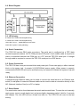
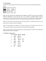
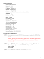
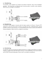
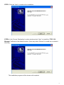
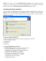
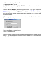
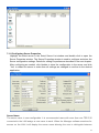
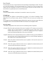
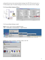
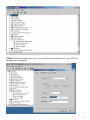
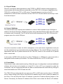
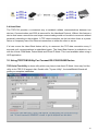
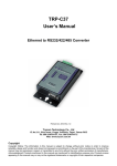
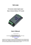
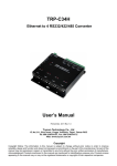
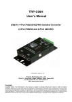
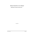
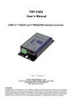
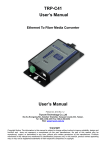
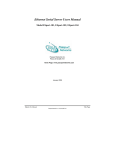
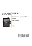
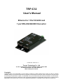
TRP-C32
User’s Manual
Ethernet to 1 Port R-S232 and
1 port RS-232/422/485 Converter
Printed DEC. 2005 Rev 1.0
Trycom Technology Co., Ltd
1F, No.2-11, Sihu street, Yingge Township, Taipei, Taiwan ROC
Tel: 886-2-86781191, Fax: 886-2-86781172
Web: www.trycom.com.tw
Copyright
Copyright Notice: The information in this manual is subject to change without prior notice in order to improve
reliability, design and function and dosed not represent a commitment on the part of the manufacturer. No part of this
manual may be reproduced, copied, or transmitted in any form without the prior written permission of manufacturer.
Acknowledgment Products mentioned in this manual are mentioned for identification purpose only. Products manes
appearing in this manual may or may not be registered trademarks or copyright of their respective companies.
1.Introduction
TRP-C32, a fast 2-port serial to Ethernet device, is designed to instantly convert data from
RS-232/422/485 interfaces to a 10/100Mbps Ethernet network running at the TCP/IP protocol.
By using existing network infrastructure the device allow you to link 2 distant serial peripherals.
You can reach TRP-C32 from Windows, Linux and UNIX without the need to modify existing
software. The TR-C32 operates in “Direct IP Mode”, “Virtual COM Mode”, and “Paired Mode”. It
has 2 synchronous DB-9 serial ports equipped 10/100 Mbps Ethernet RJ-45 connection. The
Ethernet port may auto-select 10Base-T or 100Base-TX. TRP-C32 also offers a Heart Beat
feature to ensure a reliable communicating connection. TRP-C32 will work at Loop back Mode,
all data is sent back immediately. This feature makes the connection testing easy. And the
industry standard DIN rail design enables fast and professional installation
1-1.Features
¾ DIN rail or Panel mount support.
¾ 2 serial ports interface: 1 RS-232, 1 RS-232/422/485.
¾ Auto-detecting 10/100Mbps Ethernet interface.
¾ In Server mode supports individual client sessions for security.
¾ Virtual COM drivers for Windows NT/98/ME/2000/XP.
¾ Auto direction flow control on RS-485.
¾ Provide with +/- 15KV ESD protection on RS-232/422/485 signals.
¾ Supported baud rate up to 230.4 Kbps.
¾ Power/Link/COMA/COMB Flow LED indicators.
¾ Support intranet and internet system setting function.
¾ Support screw terminal and standard external DC power adaptor.
1-2.Specification
¾ CPU: RDC 80186
¾ System memory:1MB Byte
¾ SDRAM:1MB Byte
¾ Flash:256KB
¾ Serial Memory: output: 64K bytes per port.
¾ Power Input Voltage: DC +10V to +15V.
¾ LAN: 10/100Base-T, 10/100 Mbps Auto-detecting.
¾ Serial interface: 1 RS-232/422/485 (COMA), 1 RS-232 (COMB).
¾ RS-232 signal: TX, RX, RTS, CTS, DTR, DSR, DCD, And GND (COMA,COMB)
¾ RS-422 signal: TX+,TX-,RX+,RX-,RTS+,RTS-,CTS+,CTS-,GND (COMA).
¾ RS-485 signal: Data +, Data –, GND (COMA).
¾ Data Rate: 110 bps to 230.4 k bps
¾ Parity: none, even, odd, mark, space
¾ Data Bits: 5, 6, 7 or 8
¾ Stop Bits: 1, 1.5 or 2
2
¾
¾
¾
¾
¾
¾
¾
¾
¾
Protocol: TCP, IP, ARP, DHCP, Telnet, HTTP, UDP, ICMP
Din-Rail mountable: Yes.
Power supply: Screw terminal, or external DC adapter.
Power consumption: 15V/200 mA.
Operating Temperature: 0 to 60 °C.
Storage Temperature: -20 to 70 °C.
Humidity: 10~90% Non-Condensing.
Dimensions: 151mm X 77mm X 26mm.
Weight:379g
2. Hardware Description
The following information is provided to give the user an understanding of how to connect the
TRP-C32 to the LAN and serial device. A review of the switch settings and the functionality of the
LED’s are also provided.
2-1. Panel Layout
3
2-2. Block Diagram
2-3. LED display.
B-TX/RX LED: COM-B Transiting/Receiving
A-TX/RX LED: COM-A Transiting/Receiving
LINK LED: Turn on – 100MB Ethernet Connection.
PWR LED: System is ready.(Blinking)
2-4. Serial Connection
The TRP-C32 has two DB-9 male connectors. The serial port is configured as a DTE (data
terminal equipment) device. All PC COM ports are DTE ports. A null modem cable is required to
make a connection between the COM port on a PC and the TRP-C32 serial port. A straight
through cable is required to connect the TRP-C32 serial port to a DCE device.
2-5. Power Connection
The TRP-C32 has a two pins terminal block and power jack. Power can apply on either terminal
block or the power jack. It accepts 9-15VDC/500mA power supply. When power is properly
connected the PWR LED will turn on and flash every one second to indicate the system is up and
ready.
2-6. Ethernet Connection
A straight-through Ethernet cable can be used to connect the serial server to an Ethernet hub,
switch, or wall plate. A crossover Ethernet cable can be used to make a connection directly to the
NIC (Network Interface Card) on a PC or laptop.
2-7. Reset Button
The reset button can be found between the switch and terminal block. To reset the unit manually
apply power, insert a small plastic tool, and press lightly depressing switch. Hold for 3 seconds
and release. The Link LED will turn off and turn back on. The TRP-C32 will revert to the last
setting.
4
2-8. Dip Switches
A double DIP switch allows the TRP-C32 to be placed into Console/Loop back/Default/Data
Mode.
When all these switches are moved into the ON position, theTRP-C32 enters Console Mode,
allowing configuration of the TRP-C32 from a PC running a terminal program such as
Hyper-terminal. When the TRP-C32 enters Console Mode, the Console Mode screen will appear
in the Hyper-terminal program window. The serial port settings must be 8-N-1 at 9600 baud.
When the DIP switches are switched to the ON OFF position, the TRP-C32 will work at Loop
back Mode, all data is sent back immediately.
When the DIP switches are switched to the OFF ON position, the TRP-C32 will revert to its
factory version firmware no matter what newer firmware has been upgraded.
When all of the DIP switches are switched back to the OFF position, the TRP-C32 will enter Data
Mode (RS-232, RS-422 or RS-485).
2-9. DB9 Pin Configuration
Pin RS-232
1
DCD
2
RXD
3
TXD
4
DTR
5
6
7
8
9
GND
DSR
RTS
CTS
RI
RS-422 RS-485
RXD (-)
RXD (+)
TXD (+) D (+)
TXD (-) D (-)
GND
CTS (-)
CTS (+)
RTS (+)
RTS (-)
GND
5
3. Default Settings
Model Number: TRP-C32
Password: Blank
DHCP: Disable
IP address: 192.168.1.1
Netmask: 255.255.255.0
Gateway : 192.168.1.254
Version & Date: Current firmware version number and date
Serial port: 2
Baud rate: 9600
Data/Stop bits: 8-1
Parity:
None
Flow control: None
Protocol: TCP
Serial timeout: 0 seconds
TCP alive timeout: 0 minutes
Connection mode: Server
Delimiter HEX 1: 00
Delimiter HEX 2: 00
Force transmit: 0 ms
Serial port mode: Console
Maximum connection: 1
Remote IP address: 255.255.255.255
4. Install TRP-C32 Hardware
STEP1: Connect power source with TRP-C32, if power properly supplies the PWR LED will
turn on.
Warning: User can only choose one of 2 power source, external DC-Jack or Screw
terminal DC input. Do not use external DC-Jack and screw terminal DC input
simultaneously.
STEP2: Connect TRP-C32 with internet port (Ethernet Hub or Switch) by RJ45 LAN cable.
If the cable properly connects the “LINK” LED will light up.
Green: 100MB
Yellow: 10MB
STEP3: Connect TRP-C32 with RS-232 or RS-422/485 serial device.
6
4-1. RS-485 Wiring
The RS-485 mode supports the Transmit and Receive Channels using 2-wire half-duplex
operation. The data lines are differential pair Ground provides a common mode reference.
Refer to the Pin out table for connections.
4-2. RS-422 Wiring
The RS-422 mode supports 4 channels with full duplex operation for Receive, Transmit, RTS
(Request to send) and CTS (Clear to Send). The data lines are in differential pairs. Ground
provides a common mode reference. To use handshaking Flow Control must be set to RTS/CTS
during configuration. Refer to the Pin out table for connections.
4-3. RS-232 Wiring
The RS-232 supports 8 channels plus Signal Ground and is configured as DTE like a computer.
Signals are single ended and referenced to Ground. To use handshaking, Flow Control must be
set to RTS/CTS during Configuration. Refer to the Pin out table for connections.
7
4-4. RJ-45 LAN Cable Wiring Diagram
PC To TRP-C32: Please use crossover Ethernet cable.
HUB To TRP-C32: Please using straight through cable
5. Install TRP-C32 Software
It is recommended the user install the “TRP-C3X Manager” utility software and do a search for
all TRP-C32 connected to the LAN. When this is completed a window will list the devices making
them available for configuration.
Configuring the serial server to meet your LAN and application requirement is an easy process
with the available setup menu in the “TRP-C3X Manager” software.
The following procedure installs the “TRP-C3X Manager” software.
STEP1. Inserting TRP-Series CD, in the CD-ROM and select the TRP-C32 Directory.
Run start.exe.
STEP2. The InstallShield Wizard window automatically display and start the setup procedure.
8
STEP3. Click the “Next” to continue the installation.
STEP4. In the Choose Destination Location window select “Next” to install the “TRP-C3X
Manager” software in the default location. (User may select “Browse” to install into a selected
directory).
The installation progress will be shown until complete.
9
STEP5. Click “Finish” when the InstallShield Wizard Complete screen appears. When the
installation is complete user may access to the Manager software in the program files. If loaded in
the default location Go to Start/Programs/Trycom/TRP-C3X Manager to open.
6.Updating Existing Installation
If an older version of the Manager software is already installed, the Modify, repair or remove the
program window will appear when the installation process is initiated. The recommended
procedure is to remove all installed components first. Once the software has been removed,
install the new software.
7. How to configure TRP-C32
There are 4 ways to access the Server Properties and program the TRP-C32
1. TRP-C3X Manager software.
2. Console mode.
3. Telnet, see.
4. Web Server.
7-1. Using TRP-C3X Manager Software
The “TRP-C3X Manager” software performs several functions:
A: Searching for TRP-C32 connected to the network
B: Displaying and changing the configuration of TRP-C32
C: Installing virtual COM ports on a computer
D: Displaying and configuring virtual COM ports
E: Uninstalling virtual COM ports on a computer
F: Upgrading the TRP-C32 firmware
G: Monitoring Port Status
10
H: Saving and Loading Configuration Files
7-1-1.Searching LAN for TRP-C32
Once TRP-C32 is connected to the LAN the TRP-C3X Manager software will search it and
display it in a window by name and IP address.
A. Select “TRP-C3X Manager” Utility in the program file menu. If the default location was
selected during the installation the program will be found under “Start/Programs/Trycom
/TRP-C3X” utility. As soon as the “TRP-C3X Manager” Utility opens it will initiate Searching
Server and after a few seconds the Serial Server List will display all (TRP-C31/32/34) serial
servers on the network.
B. To manually initiate a search for servers, on the menu side bar select Searching Server button.
The Search Setup box will appear.
It provides two options for searching for servers on the network:
• Specify the IP address of the Serial Server.
• Search all reachable servers
Enter the IP Address assigned to the desired Serial Server or click Search all reachable servers,
click “OK”. The Searching window is shown until all active Serial Servers on the LAN are listed
in the Serial Server List window.
11
7-1-2.Configuring Server Properties
Highlight the serial server in the Serial Server List window and double click to open the
Server Properties window. The Server Properties window is used to configure and store the
Server configuration settings. Details for setting Properties are described in the next chapter.
After configuring as needed, click Update to store the configuration in the server and click
“Yes” to restart the server to make sure all settings are changed to conform to the desired
application.
Server Name
The server name is user configurable. It is recommended users with more than one TRP-C32
connected to the LAN assign a new name to each. When the Manager software searches for
servers on the LAN it will display the server name allowing the user to distinguish between
12
TRP-C32s.
Serial Number
Each TRP-C32 has a unique serial number. This is fixed and cannot be changed.
Password
Entering a password activates a security feature on the serial server. Once a password is
entered it will be required to access the menu and make changes.
DHCP
DHCP servers are a part of numerous LAN management systems. The DHCP field has two
selections, “Enable” or “Disable”. Arrow to the desired selection and select enter.
When enabled, TRP-C32 will send a DHCP request to the DHCP server, which will assign a
dynamic IP address, netmask, and gateway to the TRP-C32. If a DHCP server is not available on
the network the TRP-C32 will time out after 10 seconds and the default values will remain. When
DHCP is enabled, the IP address, Netmask and Gateway fields become inaccessible and cannot
be changed by the user.
IP Address
A static IP address can also be assigned in this section of the menu. A dynamic address
assigned by the DHCP server may change if the TRP-C32 looses the Ethernet connection or
power is removed. The host (client) communication software requests a connection to the
specific IP address of the serial server. If the DHCP reassigns a different IP address the software
will not be able to communicate with the hardware. It is recommended to use a static IP address.
A static IP address is permanent and will not change unless changed in the menu. In most cases
the network administrator establishes the static address to be used.
Netmask
The default LAN netmask is configured for a Class C address. This maybe reconfigured by the
user.
Gateway
The gateway IP address allows users to access the serial server from outside the LAN.
MAC Address
The MAC address is not adjustable. This is assigned in the factory. Every Ethernet device
manufactured has it own unique MAC address.
Version & Date
The currently loaded version of the firmware, and when it was released, are shown here.
13
Link Status
Link status automatically displays the type of Ethernet connection. It will either display 10 BaseT
or 100BaseTX in full duplex or half duplex. This will depend on the LAN, switches, hubs used in
the LAN topology.
Server Serial Port
This field indicates the number of the port for with serial server properties are currently being
displayed. Changing the number in this field will cause all the other fields to display the
properties for the specified port. Note, however, that before changing ports, any change to
properties must be updated (Saved) or the serial server will not retain them.
Baud rate
The serial port baud rate on the TRP-C32 must match the serial baud rate of the connected
device unless using Virtual COM mode. In Virtual COM mode the software program will establish
serial settings.
Data/Parity/Stop
This setting will have to match the data format of the connected device unless using Virtual COM
mode. In Virtual COM mode the software program will establish serial settings.
Flow Control
The flow control setting must match the connected serial device unless using Virtual COM mode.
In Virtual COM mode the software program will establish serial settings.
Protocol
Select TCP or UDP protocol. If the application does not require a UDP connection, select TCP.
TCP guarantees reliable communication with error checking whereas UDP provides faster
transmission.
When UDP mode is chosen the Serial timeout, TCP alive timeout, Connection mode, Connection
at, Maximum connection and Remote IP address fields are replaced with the following three
fields: Destination IP address range, Port number and Source IP address range. In this mode the
server can be configured to broadcast data to and receive data from multiple IP addresses. Four
IP address range fields are provided.
14
Serial Timeout
Default is 0, or no timeout. Setting timeout to any value between 1 and 65535 seconds activates
it. If communications are idle for specified timeout value the serial server will reset and make
itself available for another connection.
TCP Alive Timeout
This monitors TCP activity. If TCP activity stops for the length of time specified in this field the
connection will be closed. This field can be set to any value between 0 and 255 minutes. If zero,
or no value, is entered into this field the server will not disconnect.
Connection Mode
The Connection mode field has three options, Server, Client and Client (no heartbeat). When
Client or Client (no heartbeat) is selected, the Connection at field automatically becomes active
(allowing the user to select Power up or Data arrival).
• When using the Virtual COM Port feature, select Server.
• When using a TCP or UDP Socket program, select Server.
• When using Paired Mode communication between two serial servers set up one as a Client and
the other as a Server.
• When connecting to a server that does not support Heartbeat, select Client (no heartbeat).
Delimiter HEX1 and Delimiter HEX 2
These two fields allow the user to enter two ASCII characters (in hex format) that delimit the
beginning and end of a message. When a message with both these delimiters is received at the
serial port, the data contained in the serial buffer is placed in an Ethernet packet and sent out the
Ethernet port. If only Delimiter 1 is set (Delimiter 2 is zero or blank), upon receiving Delimiter 1
the TRP-C32 will put all the data in the serial buffer in an Ethernet packet and send it out the
Ethernet port. If serial data greater than 1 kilobyte is received it will automatically be placed in an
Ethernet packet and sent out the Ethernet port.
15
Force Transmit
This field allows the user to set a maximum time limit between transmissions of data. The value
set in this field multiplied by 100 ms determines the Force Transmit time. When the elapsed time
reaches the time configured in this field, the TCP/IP protocol will pack the data currently in the
serial buffer into a packet and send it out the Ethernet port.
Port Status
This field indicates whether a serial port is connected to a server or by a client.
TCP/UDP Port
The TCP/UDP Port defines a communication port number. In all modes of operating, Virtual
COM, Direct IP, and Paired modes, both the TCP/UDP Client and server port settings must
match.
For example the Virtual COM defaults setting TCP/UDP Port # 4000. If the port # of the TRP-C32
is changed to 4001, the Virtual COM TCP/UDP Port will have to be changed to 4001.
Serial Port Mode
This allows configuration of the serial server for the following modes of operation:
• Console: When this mode is selected and the server is updated, a PC running a communication
program such as Hyper-terminal can communicate with the serial server via the
Console Mode serial port (Port 1 on TRP-C32), displaying the Server Properties
screen and allowing configuration of the server and its ports.
• Upgrade: When this mode is selected and the server is updated, firmware can be uploaded into
the serial server via the Console Mode serial port or a virtual COM port appeared to
the number of the Console Mode serial port.
• Default: When this mode is selected and the server is updated, it will revert the server to its
default configuration.
• RS-232:
When this mode is selected and the server is updated, the selected serial port will
become a RS-232 serial port on the server.
• RS-422:
When this mode is selected and the server is updated, the selected serial port will
become a RS-422 serial port on the server.
• RS-485:
When this mode is selected and the server is updated, the selected serial port will
become to a RS-485 serial port on the server.
16
Connection At
When the Connection Mode field is set to Client or Client (no heartbeat), this field becomes
active, allowing the TRP-C32 (acting as a client) to connect to the server either on Power up or
on Data Arrival (first character arriving).
Maximum Connection
This field allows the user to configure the Serial Server to have up to eight TCP connections.
Remote IP Address
This is a security feature that is activated when the IP address of the desired client is
programmed into the remote IP Address setting of the menu. This tells the TRP-C32 to
communicate with only the listed IP address and to filter out all other requests for connection.
The TRP-C32 is setup in the menu as a TCP or UDP server to us this feature.
The default setting is 255.255.255.255. It is recommended not to change this setting until the
application has been tested and is communicating properly. At that point the address filtering
feature of the TRP-C32 can be activated.
Update/Save
Server properties must be updated separately for each serial port. Updating varies slightly
depending on which of the four configuration user interfaces are used.
Updating the Server Properties in Manager Software
From the Server Properties screen, click the Update button to store the configuration settings for
the currently selected port. The “vcomui” dialogue box will appear indicating you must restart
the device before the new settings will take effect. Click Yes.
7-2 Using Console Mode
The console mode allows access to the TRP-C32 setup menu. This is one way to reconfigure the
default settings for the application. A serial connection is made between a COM port on the PC
and the TRP-C32 serial port A with a null modem cable. In console mode, the serial port defaults
to an RS-232 interface.
The TRP-C32 serial port default settings are, baud rate 9600, 8 data bits, no parity, and 1 stop bit.
Hyper Terminal should be used for this type of setup. Hyper Terminal’s serial settings are
17
configured the same as the mentioned default settings of the TRP-C32 and must be set to
VT100 emulation mode. The default settings are used only if they have not been changed
7-2-1 Console Mode Hardware Wiring
7-2-2 Console Mode Software Install
STEP1. Select “Hyper Terminal” WINDOWS Utility
Start ---Accessories---Communications --- Hyper Terminal
STEP2.Select “New Connection” and Enter a name, click “OK”
18
.
STEP3. Enter the COM Port number that TRP-C32 connect using, click “OK”
STEP4. Press the “Space bar” the TRP-C32 firmware setting screen will show.
You can set the TRP-C32 by Console mode.
7-3.Using Telnet
Telnet can be used to configure the TRP-C32 Serial Server from any PC on the LAN. The Telnet
window displays the same configuration information shown in Console Mode and allows server
properties to be configured. See chapter 6 for details on Server Properties.
Ensure the PC and TRP-C32 are connected to the LAN, and the serial server is in RS-232,
RS-422 or RS-485 mode before you can telnet to it and access the configuration screens. From
the Desktop, click Start, and then run. The Run dialogue box will open. Type in Telnet and the IP
address of the Serial Server which to be configured, click OK.
19
STEP1. Select Start then Click “RUN” then key in the “Telnet IP”
STEP2. Click the “OK” TRP-C32 firmware setting will show as following screen. You can set
the TRP-C32 by Telnet mode.
7-4 Using the WEB Server mode
The Web Server can be used to configure the TRP-C32 Serial Server from any web browser
software (such as Internet Explorer). Server properties can be set up using three browser pages.
20
See chapter 6 for details on Server Properties.
In Internet Explorer type the IP Address of the Serial Server into the address field near the top of
the window and press the Enter key. The following window will appear:
8 Virtual-Com
The Virtual COM Port feature allows Windows platform software using standard API calls to be
used in an Ethernet application.
Running the Install Virtual COM port software adds a COM Port in the Device Manager of the
operating system. The COM port will look like a standard COM port to Windows software used in
most applications allowing the software to open a connection with the serial port located
anywhere on the LAN. When using the virtual COM port the TRP-C32 is configured as a TCP or
21
UDP Server.
8-1 Installing Virtual COM Port
STEP1. On the Desk Top select Start/Programs/Trycom /Install Virtual COM.
STEP2. Select the Search all reachable servers check box, then click OK.
STEP3. The Install Virtual COM program will automatically search the LAN for all available
TRP-C32 serial servers and display them in the Found Server window. Highlight the desired
serial server and click Install. The COMInst window appears.
STEP4. When the COMInst window opens select COM port # to map the serial server to. The
Flow Control, Protocol, IP Address, and Port Number will mirror the settings of the selected serial
server. Highlight the desired COM port # and select OK.
22
Note1. If any settings are changed in this part of the Virtual COM setup, it will only affect
the settings in the operating system Device Manager. It will not change the settings in the
TRP-C32.
Note2. The settings of the Virtual COM port in the Device Manager and the TRP-C32
Configuration menu must match. If the settings do not match, the software connecting to
the Virtual COM port will be unsuccessful in opening the COM port.
Note3. In Windows XP a Hardware Installation window stating that the drivers have not
been tested by Microsoft may appear. Select “Continue Anyway” to proceed with the
installation.
STEP5. When Virtual Com installation completed, click close on the Found Server window to
close Found Server window. To confirm installation, go to the Device Manager and select Ports
(COM & LPT). The installed Virtual COM port will be displayed as TRP-C32 COM#.
8-2 Configuring Virtual COM Port
The Virtual COM port can be configured in the Device Manager of the operating system or
the Manager software. In either case the IP Address, Port #, Protocol, and Flow Control
settings must match the TRP-C32 settings for the software to open the Virtual COM port.
STEP1. At the Desk Top select Start/Program/Trycom/TRP-C3X Manager. Double click the
Virtual COM Configuration button.
STEP2. Double click the COM # displayed in the screen to open the configuration window.
23
STEP3. Make the adjustments and select OK to complete the changes.
8-3.Configuration with Device Manager
STEP1. On the Desk Top select Start/Settings/Control Panel. Select the System Icon when the
Control Panel window opens.
STEP2. In the System Properties window select the Device Manager Button.
STEP3. In the Device Manager, select the + button next to Ports (COM & LPT) to expand and
see the TRP-C32 (COM #). Double click TRP-C32 (COM #) to open the Properties window.
24
STEP4. Select the Configuration tab. From here the same settings found in the TRP-C32
Manager can be adjusted.
25
8-4. Uninstalling the Virtual COM Port
The TRP-C3X Manager software Uninstall Virtual Com port feature will remove the mapped
COM port in the Device Manager of Windows 2000 and XP operating systems. It may also be
removed in the Device Manager of Windows 98, ME, NT, 2000, and XP. Windows 98 users will
also find a Remove Virtual COM feature in the programs file.
8-4-1. Removing the Virtual COM port with Manager Software
STEP1 At the Desk Top select Start/Programs/Trycom/TRP-C3X Manager.
STEP2.In the Manager window, select Virtual COM Configuration. Highlight the mapped COM
port number to be removed.
STEP3 Select Uninstall Virtual COM button. The Manager will ask for confirmation. Select “Yes”
to complete the uninstall procedure.
8-4-2. Removing the Virtual COM Port using Device Manager
The screen shots were taken from a Windows XP operating system
STEP1. On the Desktop select Start/Settings/Control Panel. Select the System icon when the
Manager window opens.
STEP2. Select Device Manager in the Systems Properties window. In the Device Manger
Window, select the + next to Ports (COM & LPT) to expand.
STEP3. Highlight the desired TRP-C32 (COM #) to be removed, go the Action tab at the top of
the window and select uninstall. A confirm Device Removal window will appear. Select
OK to continue.
STEP4. The TRP-C32 COM # will be removed and the Device Manager window will refresh
and display the remaining COM ports.
Once all the changes have been made move to the Configuration screen, select Save and
press Enter. The restart message will appear. Select “Yes” to save changes. This is necessary to
write the settings to the server.
9. Application
The TRP-C32 allows serial devices to communicate over a LAN or Intranet network. Serial
devices are no longer limited to a physical connection to the PC COM port. They can be installed
anywhere on the LAN using TCP/IP or UDP/IP communications. This will also allow traditional
PC COM ports access to a serial device anywhere on the LAN network.
26
9-1 Direct IP Mode
Direct IP connections allow applications using TCP/IP or UDP/IP network socket programs to
communicate with the asynchronous serial port on the TRP-C32. In this type of application the
TRP-C32 is configured to TCP or UDP server. The socket program running on the PC
establishes a communication connection with the TRP-C32. The raw data is sent directly to and
from the serial port.
9-2 Virtual COM Mode
The Virtual COM mode requires the installation of a driver. When installed a new COM port is
added to the Device Manager. Windows programs using standard Windows API calls will be able
to interface with Virtual ports. The PC will act as the host connecting to the TRP-C32 when the
program opens the virtual COM port.
Once the connection is made, the LAN is transparent to the serial device. Applications work just
as if the serial device is connected a host’s physical COM port. The virtual COM port converts the
application’s data into IP packet destined for the TRP-C32, which in turn converts the IP packet
back to serial data.
In this mode, theTRP-C32 must be set to either TCP/server or UDP/server in the menu with a
designated communication port number. The virtual COM driver is a TCP or UDP client.
9-3 Paired Mode
Paired mode is also called serial tunneling. When this type of configuration is selected additional
software will not have to be loaded on a host PC. In fact a PC is not required to make the
connection. Any two dumb serial devices are able to communicate with each other by through a
serial link between two TRP-C32 and the LAN.
Two TRP-C32 are configured with one setup as a TCP or UDP client and the other to TCP/UDP
server. When setting up the Server, the Remote IP address section must contain the address of
the Client. This will allow the Client’s IP address to pass the IP address-filtering feature of the
Server. Conversely, the Remote IP address of the Client must contain the Server’s IP address.
27
9-4 Heart Beat
The TRP-C32 provides a convenient way to establish reliable communications between two
devices. Communication port 5300 is reserved for the Heartbeat Protocol. Without this feature a
device that loses a connection and stops communicating would not be able to reconnect without
personally attending to the problem. A TCP data connection can be lost when there is a power
failure or temporary loss of an Ethernet connection on either the client or server.
If a loss occurs the Heart Beat feature will try to reconnect the TCP data connection every 5
seconds until communications is established again. The Heart Beat feature is available to use
with the Virtual COM Mode, Paired Mode and Direct IP Mode. This is not available when using a
UDP application.
10. Using TRPCOM Utility For Connect RS-232/422/485 Device
TRP-Serial Test Utility is demo utility which may help to test direct IP Mode .User may find the
utility in the TRP-C32 support disk. Double click “Trycom Utility”, the installShield Wizard will
guide you complete installation.
28
User can directly link TRP-C32 to Trycom Remote IO Modules by RS-485, The basic wiring
connect.
11.RS-232/422 Loop Test
STEP1. Adjust the TRP-C32’s Switch to the “ON, OFF”
STEP2. Run the “Install Virtual-Com” and setting the Virtual-COM.
STEP3. Run the Demo Utility, click the “Settings” then setup the com port status and click the
“Action”!
29
12 Troubleshooting
Q: Why sometimes Hyperterminal loses characters or display funny characters?
A: This happens when you open a new Hyperterminal connection and keep inputting the same
character. The reason is before Hyperterminal receiving two different characters from the other
end, its status is Auto detects, and your port settings haven’t fully take effect, so the transferred
data is not predicable. To solve this problem, input two different characters from the other end,
then the Hyperterminal status will show your port settings such as 9600 8-N-1, save this
Hyperterminal connection. Next you open your saved Hyperterminal connection, everything will
be fine.
Q: What should I do when I forget the IP address or baud rate setting of a TRP-C32?
A: You can use the searching capability to get the information of all TRP-C32 on the network.
Double clicks on the searched result will show the detail configuration parameters of the device.
Q: Why I cannot open virtual COMx?
A: The server settings and virtual COMx settings may not match, please make sure their IP
address, protocol, port and flow control mode are the same, and the remote IP address should
be the host IP address. Besides the TRP-C32 cannot be at Console mode.
Q: Why the arrow keys of hyperterminal in Windows 2000 do not work in Console mode and
telnet?
A: Please download new version of hyperterminal. The hyperterminal comes with Windows
2000 does not send the arrow key code properly.
Q: Why I am unable to change the parameters of port 1?
A: Serial port 1 is designated console port. The default setting for the console port is 9600 8-N-1.
If the serial port 1 is set to console port. It will use the default value that is why it does response
30
to the change. Please check hardware switch or server properties page to see if the serial port
mode of the port1 is set to console. Please change it to other mode then its parameter can be
changed.
Q: Why the parameters in the web console are different than those in the server properties of
management utility?
A: The edited parameters in the web console only take effect after reset TRP-C32. Web console
show the edited configuration while in the management utility show the running configuration.
That is why they might appear differently it is not recommended to edit server's configuration
using two different tools at the same time. Because all change could be over-written by other
method.
31