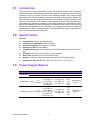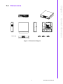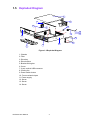
1
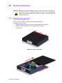
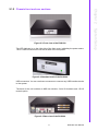
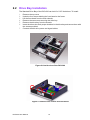
User Manual DVS-500 Industrial Compact Platform for PC Based Video Surveillance Copyright The documentation and the software included with this product are copyrighted 2008 by Advantech Co., Ltd. All rights are reserved. Advantech Co., Ltd. reserves the right to make improvements in the products described in this manual at any time without notice. No part of this manual may be reproduced, copied, translated or transmitted in any form or by any means without the prior written permission of Advantech Co., Ltd. Information provided in this manual is intended to be accurate and reliable. However, Advantech Co., Ltd. assumes no responsibility for its use, nor for any infringements of the rights of third parties, which may result from its use. Note The information in this document is provided for reference only. Advantech does not assume any liability arising out of the application or use of the information or products described herein. This manual is subject to change without notice. On-line Technical Support For technical support and service, please visit our support website at: http://www.advantech.com/support DVS-500 User Manual Part No. 2006V50000 Edition 1 Printed in Taiwan April 2008 ii Product Warranty (2 years) Advantech warrants to you, the original purchaser, that each of its products will be free from defects in materials and workmanship for two years from the date of purchase. This warranty does not apply to any products which have been repaired or altered by persons other than repair personnel authorized by Advantech, or which have been subject to misuse, abuse, accident or improper installation. Advantech assumes no liability under the terms of this warranty as a consequence of such events. Because of Advantech’s high quality-control standards and rigorous testing, most of our customers never need to use our repair service. If an Advantech product is defective, it will be repaired or replaced at no charge during the warranty period. For outof-warranty repairs, you will be billed according to the cost of replacement materials, service time and freight. Please consult your dealer for more details. If you think you have a defective product, follow these steps: 1. Collect all the information about the problem encountered. (For example, CPU speed, Advantech products used, other hardware and software used, etc.) Note anything abnormal and list any onscreen messages you get when the problem occurs. 2. Call your dealer and describe the problem. Please have your manual, product, and any helpful information readily available. 3. If your product is diagnosed as defective, obtain an RMA (return merchandise authorization) number from your dealer. This allows us to process your return more quickly. 4. Carefully pack the defective product, a fully-completed Repair and Replacement Order Card and a photocopy proof of purchase date (such as your sales receipt) in a shippable container. A product returned without proof of the purchase date is not eligible for warranty service. 5. Write the RMA number visibly on the outside of the package and ship it prepaid to your dealer. Technical Support and Assistance 1. 2. Visit the Advantech web site at www.advantech.com/support where you can find the latest information about the product. Contact your distributor, sales representative, or Advantech's customer service center for technical support if you need additional assistance. Please have the following information ready before you call: – Product name and serial number – Description of your peripheral attachments – Description of your software (operating system, version, application software, etc.) – A complete description of the problem – The exact wording of any error messages Document Feedback To assist us in making improvements to this manual, we would welcome comments and constructive criticism. Please send all such - in writing to: [email protected] iii DVS-500 User Manual Packing List Before setting up the system, check that the items listed below are included and in good condition. If items received do not match those in the table, please contact your dealer immediately. Item Box Safety Instructions 1. 2. 3. Read these safety instructions carefully. Keep this User Manual for later reference. Disconnect this equipment from any AC outlet before cleaning. Use a damp cloth. Do not use liquid or spray detergents for cleaning. 4. For plug-in equipment, the power outlet socket must be located near the equipment and must be easily accessible. 5. Keep this equipment away from humidity. 6. Put this equipment on a reliable surface during installation. Dropping it or letting it fall may cause damage. 7. The openings on the enclosure are for air convection. Protect the equipment from overheating. DO NOT COVER THE OPENINGS. 8. Make sure the voltage of the power source is correct before connecting the equipment to the power outlet. 9. Position the power cord so that people cannot step on it. Do not place anything over the power cord. 10. All cautions and warnings on the equipment should be noted. 11. If the equipment is not used for a long time, disconnect it from the power source to avoid damage by transient overvoltage. 12. Never pour any liquid into an opening. This may cause fire or electrical shock. 13. Never open the equipment. For safety reasons, the equipment should be opened only by qualified service personnel. 14. If one of the following situations arises, have the equipment checked by service personnel: – The power cord or plug is damaged. – Liquid has spilled into the equipment. – The equipment has been exposed to moisture. – The equipment does not work well, or you cannot get it to work according to the user's manual. – The equipment has been dropped and damaged. – The equipment has obvious signs of breakage. 15. DO NOT LEAVE THIS EQUIPMENT IN AN ENVIRONMENT WHERE THE STORAGE TEMPERATURE MAY GO BELOW -20° C (-4° F) OR ABOVE 60° C (140° F). THIS COULD DAMAGE THE EQUIPMENT. THE EQUIPMENT SHOULD BE IN A CONTROLLED ENVIRONMENT. 16. CAUTION: DANGER OF EXPLOSION IF BATTERY IS INCORRECTLY REPLACED. REPLACE ONLY WITH THE SAME OR EQUIVALENT TYPE RECOMMENDED BY THE MANUFACTURER, DISCARD USED BATTERIES ACCORDING TO THE MANUFACTURER'S INSTRUCTIONS. The sound pressure level at the operator's position according to IEC 704-1:1982 is no more than 70 dB (A). DVS-500 User Manual iv DISCLAIMER: This set of instructions is given according to IEC 704-1. Advantech disclaims all responsibility for the accuracy of any statements contained herein. Wichtige Sicherheishinweise 1. 2. 3. Bitte lesen sie Sich diese Hinweise sorgfältig durch. Heben Sie diese Anleitung für den späteren Gebrauch auf. Vor jedem Reinigen ist das Gerät vom Stromnetz zu trennen. Verwenden Sie Keine Flüssig-oder Aerosolreiniger. Am besten dient ein angefeuchtetes Tuch zur Reinigung. 4. Die NetzanschluBsteckdose soll nahe dem Gerät angebracht und leicht zugänglich sein. 5. Das Gerät ist vor Feuchtigkeit zu schützen. 6. Bei der Aufstellung des Gerätes ist auf sicheren Stand zu achten. Ein Kippen oder Fallen könnte Verletzungen hervorrufen. 7. Die Belüftungsöffnungen dienen zur Luftzirkulation die das Gerät vor überhitzung schützt. Sorgen Sie dafür, daB diese Öffnungen nicht abgedeckt werden. 8. Beachten Sie beim. AnschluB an das Stromnetz die AnschluBwerte. 9. Verlegen Sie die NetzanschluBleitung so, daB niemand darüber fallen kann. Es sollte auch nichts auf der Leitung abgestellt werden. 10. Alle Hinweise und Warnungen die sich am Geräten befinden sind zu beachten. 11. Wird das Gerät über einen längeren Zeitraum nicht benutzt, sollten Sie es vom Stromnetz trennen. Somit wird im Falle einer Überspannung eine Beschädigung vermieden. 12. Durch die Lüftungsöffnungen dürfen niemals Gegenstände oder Flüssigkeiten in das Gerät gelangen. Dies könnte einen Brand bzw. elektrischen Schlag auslösen. 13. Öffnen Sie niemals das Gerät. Das Gerät darf aus Gründen der elektrischen Sicherheit nur von authorisiertem Servicepersonal geöffnet werden. 14. Wenn folgende Situationen auftreten ist das Gerät vom Stromnetz zu trennen und von einer qualifizierten Servicestelle zu überprüfen: 15. Netzkabel oder Netzstecker sind beschädigt. 16. Flüssigkeit ist in das Gerät eingedrungen. 17. Das Gerät war Feuchtigkeit ausgesetzt. 18. Wenn das Gerät nicht der Bedienungsanleitung entsprechend funktioniert oder Sie mit Hilfe dieser Anleitung keine Verbesserung erzielen. 19. Das Gerät ist gefallen und/oder das Gehäuse ist beschädigt. 20. Wenn das Gerät deutliche Anzeichen eines Defektes aufweist. 21. VOSICHT: Explisionsgefahr bei unsachgemaben Austausch der Batterie.Ersatz nur durch densellben order einem vom Hersteller empfohlene-mahnlichen Typ. Entsorgung gebrauchter Batterien navh Angaben des Herstellers. 22. ACHTUNG: Es besteht die Explosionsgefahr, falls die Batterie auf nicht fachmännische Weise gewechselt wird. Verfangen Sie die Batterie nur gleicher oder entsprechender Type, wie vom Hersteller empfohlen. Entsorgen Sie Batterien nach Anweisung des Herstellers. 23. Der arbeitsplatzbezogene Schalldruckpegel nach DIN 45 635 Teil 1000 beträgt 70dB(A) oder weiger. Haftungsausschluss: Die Bedienungsanleitungen wurden entsprechend der IEC704-1 erstellt. Advantech lehnt jegliche Verantwortung für die Richtigkeit der in diesem Zusammenhang getätigten Aussagen ab. v DVS-500 User Manual Safety Precaution - Static Electricity Follow these simple precautions to protect yourself from harm and the products from damage. To avoid electrical shock, always disconnect the power from your PC chassis before you work on it. Don't touch any components on the CPU card or other cards while the PC is on. Disconnect power before making any configuration changes. The sudden surge of power as you connect a jumper or install a card may damage sensitive electronic components. DVS-500 User Manual vi Contents Chapter 1 General Information ............................1 1.1 1.2 1.3 Introduction ............................................................................................... 2 Specifications ............................................................................................ 2 Power Supply Options............................................................................... 2 Table 1.1: Power Supply Options ................................................ 2 Dimensions ............................................................................................... 3 Figure 1.1 Dimension Diagram .................................................... 3 Exploded Diagram..................................................................................... 4 Figure 1.2 Exploded Diagram ...................................................... 4 1.4 1.5 Chapter 2 System Setup .......................................7 2.1 System Installation .................................................................................... 8 2.1.1 Removing the top cover ................................................................ 8 Figure 2.1 Top cover screw ......................................................... 8 Figure 2.2 Top removal direction ................................................. 8 2.1.2 Chassis front and rear sections .................................................... 9 Figure 2.3 Front view of the DVS-500 ......................................... 9 Figure 2.4 Standard bezel of the DVS-500.................................. 9 Figure 2.5 Rear view of the DVS-500 .......................................... 9 Drive Bay Installation .............................................................................. 10 Figure 2.6 Inside view of the DVS-500 ...................................... 10 Figure 2.7 Remove four screws from the frame ........................ 10 Figure 2.8 Lift up and remove from the frame ........................... 11 Figure 2.9 Remove two screws from drive bay.......................... 11 Figure 2.10Remove drive bay from main chassis....................... 11 Figure 2.11Remove 4/8 screws from drive bay with one/two HDD(s)...................................................................... 12 Figure 2.12Lift HDD(s) from drive bay ........................................ 12 Figure 2.13Securing HDD to the drive bay ................................. 12 Motherboard Installation.......................................................................... 13 Figure 2.14Inside view of the DVS-500 ...................................... 13 Figure 2.15Lift Riser bracket....................................................... 13 Figure 2.16Release all screws from M/B and Lift M/B................ 14 2.3.1 System status LED .................................................................... 14 Figure 2.17Standard bezel of the DVS-500................................ 14 Figure 2.18The customized bezel of the DVS-500 ..................... 14 2.3.2 Power status LED ....................................................................... 15 2.3.3 Power supply .............................................................................. 15 Figure 2.19DVS-500 power supply top view............................... 15 Figure 2.20DVS-500 power supply............................................. 16 Figure 2.21Rear view release screws from power supply .......... 16 Figure 2.22Lift the power supply................................................. 16 2.3.4 Cooling fan, filter ........................................................................ 17 Figure 2.23Remove the system fan from main chassis.............. 17 Figure 2.24Remove filters from main chassis............................. 17 2.2 2.3 Appendix A Exploded Diagram .............................19 A.1 Exploded Diagram................................................................................... 20 Figure A.1 Exploded Diagram .................................................... 20 vii DVS-500 User Manual DVS-500 User Manual viii Chapter 1 1 General Information 1.1 Introduction The DVS-500 is a high performance video surveillance platform with a compact industrial chassis. Its cooling system has been optimally designed to improve thermal conditions, and it has lower acoustics when installing multiple video capture cards and hard drives. Combined with an industrial main board with longevity support, the DVS-500 offers a wide range of performance requirements from the Celeron D to the Core 2 Duo processors. The optional remote control module helps the system integrator add easy interactive functions to their DVR applications. Advantech’s quality assurance integration test and certification for different video capture cards give the system the best reliability for 24x7 operation. The compact size, minimum noise and rugged design makes it the ideal platform for applications like retail, community, factory, or Small and Medium Enterprises. 1.2 Specifications General Construction: Heavy duty steel chassis Indicators on front panel: LEDs for Power Disk drive capacity: two internal 3.5°± HDD Switches on Rear: Power switch Cooling system: One easy-to-replace 18.15 CFM cooling fans and two Air Filters. Air filters: three 110 x 44 mm filters on the rear plate Riser card: supports up to two PCI add-in cards Weight: 8.3 kg (18.3 lb) entire system including a 220 W power supply Dimensions (W x H x D): 370 X 88 x 370 mm (14.6" x 3.5" x 14.6") 1.3 Power Supply Options Table 1.1: Power Supply Options Part Number Specifications Safety MTBF +5 V @ 16 A, +3.3 V @ 14 A, +5 V @ 0.3 A, AC +12 V @ 14 A, +3.3 V @ 0.3 A, 1757000878 180W 100~240 V -12 V @ 0.5 A, +12 V @ 1.5 A +5 Vsb @ 2 A UL TUV CE CCC CB 100,000 hours @ 25° C +5 V @ 16 A, +3.3 V @ 14 A, +5 V @ 0.5 A, +12 V1 @ 16A, AC +3.3 V @ 0.5 A, 1757001517 220 W 100~240 V +12 V2 @ 10A, +12 V @ 1.0 A -12 V @ 0.8 A, +5 Vsb @ 2.5 A UL TUV CE CCC CB 100,000 hours @ 25° C DVS-500 User Manual Watt Input Output 2 Mini-Load Chapter 1 1.4 Dimensions 370 380 General Information 370 88 Unit: mm Figure 1.1 Dimension Diagram 3 DVS-500 User Manual 1.5 Exploded Diagram 6 4 5 14 9 8 12 7 12 10 11 3 1 2 Figure 1.2 Exploded Diagram 1: Chassis 2: Filter 3: Drive bay 4: Riser bracket 5: Bracket linking bar 6: Cover 7: 2 port vertical USB connector 8: Cooling fan 9: Power switch button 10: Front mechanical part 11: Power supply 12: Screw 13: Screw 14: Screw DVS-500 User Manual 4 13 Chapter 1 General Information DVS-500 User Manual 5 DVS-500 User Manual 6 Chapter 2 System Setup 2 2.1 System Installation Warning! Before starting the installation process, be sure to shut off all power to the chassis. Do this by turning off the power switch, and unplugging the power cord from the power outlet. When in doubt, consult with an experienced technician. 2.1.1 Removing the top cover First, remove the chassis cover. The top cover is fixed to the chassis by three thumbscrews. To remove the top covers: 1. Release two thumbscrews on the rear upper side of the chassis. 2. Release one thumbscrew on the left side of the chassis. 3. Lift the cover. Figure 2.1 Top cover screw Figure 2.2 Top removal direction DVS-500 User Manual 8 Chapter 2 2.1.2 Chassis front and rear sections The LED indicator is on the right side of the front cover, indicating the power status. The 2 x USB connectors are on the left side of the front panel. Figure 2.4 Standard bezel of the DVS-500 USB connectors: You can use these connectors to connect any USB interface device to the system. The back of the unit includes an M/B rear window, 2-slot I/O brackets and 1-D-I/O module option. Figure 2.5 Rear view of the DVS-500 9 DVS-500 User Manual System Setup Figure 2.3 Front view of the DVS-500 2.2 Drive Bay Installation The Standard Drive Bay of the DVS-500 can hold 2 x 5.25" disk drives. To install: 1. Remove the top cover 2. Undo the four screws holding the front bezel to the frame. 3. Lift the front bezel from the main chassis. 4. Remove the two screws securing the drive bay. 5. Remove the drive bay from the chassis. 6. Insert the drives into their proper locations in the drive bay and secure them with the screws provided. 7. Connect the disk drive power and signal cables. Figure 2.6 Inside view of the DVS-500 Figure 2.7 Remove four screws from the frame DVS-500 User Manual 10 Chapter 2 Figure 2.9 Remove two screws from drive bay Figure 2.10 Remove drive bay from main chassis 11 DVS-500 User Manual System Setup Figure 2.8 Lift up and remove from the frame Figure 2.11 Remove 4/8 screws from drive bay with one/two HDD(s) Figure 2.12 Lift HDD(s) from drive bay Figure 2.13 Securing HDD to the drive bay DVS-500 User Manual 12 The DVS-500 product, without an internal M/B, has no power supply and a momentary switch on the front panel. The momentary switch is suitable for use with an ATX power supply such as a 180W or 220W Flex type. Please plug the 20-pin ATX power connector to your ATX M/B, and then connect the POWER SW wire to your ATX M/B to finish the installation. Please refer to your ATX M/B installation guide for correct connection. Chapter 2 2.3 Motherboard Installation System Setup Figure 2.14 Inside view of the DVS-500 Figure 2.15 Lift Riser bracket 13 DVS-500 User Manual Figure 2.16 Release all screws from M/B and Lift M/B 2.3.1 System status LED The System Status LED is displayed below: Figure 2.17 Standard bezel of the DVS-500 The LED bezel only has one LED indicator which indicates power status. The LED is green when the power supply is working normally. Figure 2.18 The customized bezel of the DVS-500 These two types of bezel are available upon request, with eight LED Indicators of which the use is decided by cable connections. There is a maximum of eight signal devices supported by the LED indicators. DVS-500 User Manual 14 The Power Status LED indicates the status of the voltage signals. Description Light No light +3.3V +3.3V signal Normal No output +5V +5V signal Normal No output +12V +12V signal Normal No output -5V -5V signal Normal No output -12V -12V signal Normal No output When an LED fails to light, it indicates a problem with one of the voltage signals. Check to make sure that the power supply connector is properly attached to the motherboard. If the problem persists, consult an experienced technician. 2.3.3 Power supply The DVS-500 power supply supports both a full range of connectors and an inner cooler system without any mechanical modifications. Figure 2.19 DVS-500 power supply top view 15 DVS-500 User Manual System Setup LED Chapter 2 2.3.2 Power status LED Figure 2.20 DVS-500 power supply Figure 2.21 Rear view release screws from power supply Figure 2.22 Lift the power supply DVS-500 User Manual 16 Cooling fan, filter There is one cooling fan located inside the chassis. The cooling fan is easy to maintain and provides adequate cooling to the system by blowing air inward. If the cooling fan fails, the user will see that the fan on the left side of the system has stopped. A defective fan should be replaced immediately; please refer to Figure 2.23. The connector is a standard motherboard fan-plug. Additionally, if the filter is blocked with dust or other particles, please refer to Figure 2.24 which describes the procedure for replacing a filter. Finally, if the inner power supply fan fails, please replace it with another to ensure the system will work reliably. Chapter 2 2.3.4 System Setup Figure 2.23 Remove the system fan from main chassis Figure 2.24 Remove filters from main chassis 17 DVS-500 User Manual DVS-500 User Manual 18 Appendix A A Exploded Diagram A.1 Exploded Diagram 6 4 5 14 9 8 12 7 12 10 11 3 1 2 Figure A.1 Exploded Diagram 1: Chassis 2: Filter 3: Drive bay 4: Riser bracket 5: Bracket linking bar 6: Cover 7: 2 port vertical USB connector 8: Cooling fan 9: Power switch button 10: Front mechanical part 11: Power supply 12: Screw 13: Screw 14: Screw DVS-500 User Manual 20 13 Appendix A Exploded Diagram DVS-500 User Manual 21 www.advantech.com Please verify specifications before quoting. This guide is intended for reference purposes only. All product specifications are subject to change without notice. No part of this publication may be reproduced in any form or by any means, electronic, photocopying, recording or otherwise, without prior written permission of the publisher. All brand and product names are trademarks or registered trademarks of their respective companies. © Advantech Co., Ltd. 2008