1
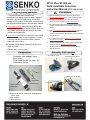
XP Fit Plus SC 900 µm
Field Installable Connector
Instruction Manual (ETP-1008-001-02)
For your safety operation
This product has been designed and
manufactured to assure personal safety. Improper
operation can result in bodily injury and serious
damage to this product. Please read and observe all
warnings instructions given in this operation manual.
★ Wear safety glasses before handling optical fiber
to protect the eyes. Small pieces of glass fiber are
very sharp and might get into the eyes or under
the skin and cause injury.
★ Never look into the end of a connector or an optical
fiber which may have a laser coupled to it. Laser
light may damage your eyes. Please note that
laser light is not visible.
★ If working in high places, please be careful not to
drop any tools.
(Please use a wrist strap etc.)
!
Precautions
1. Improper assembly will result in a loss of performance.
Please read instructions given in this operation manual.
2. The product is sensitive to dirt or dust. Do not take
connector out of the package until it is to be used.
3. The performance will be influenced by the cleaved fiber
surface condition. Please use a cleaver that has a good
blade.
4. Please insert the fiber into the connector slowly. If the fiber
is roughly inserted, it might be damaged or broken,
leading to product failure . Broken fiber could be scattered
in all directions.
5. Do not remove the dust cap until the connector has been
completely assembled.
6.
A proper amount of index matching gel is applied in the
connector. Do not insert fiber more than once.
7.
Product properties are referenced to specification No.
ETP-0109-001-xx
Assembly tools example
Composition
Connector (with wedge): 10pcs
Boot: 10pcs
Fiber holder for 900 µm fiber: 1pc
Assembling Jig:1pc
1 Fiber cleaver FC-7
2 Jacket remover JR-25
Boot
2 Jacket remover JR-M03
SC for
900µm fiber
Assembling Jig
Fiber Holder for
900µm fiber
Following tools shall be required for assembling the
above parts,
1. Fiber Cleaver
2. Jacket Remover
0.25 to 0.125mm
0.9 to 0.25mm
“Q-SC” for 0.9mm fiber Assembly Procedure
SUMITOMO ELECTRIC INDUSTRIES, LTD.
【2】Setting connector
【1】Preparing connector
wedge
!
!
connector
Be sure to wear
Safety Glasses
【3】Preparing the fiber holder
“U” shaped
area must
be free of
debris/dust.
Cover 2
Cover 1
Guide
Correct
Be sure there is no space
between the wedge and
connector, if there is, push the Set circular groove of connector
wedge and connector together tightly onto semicircular ridge of “U”
shaped shelf of Jig.
to realign.
Remove 30
to 35 mm of
900 µm jacket using
jacket remover
up
Setting fiber on the
fiber holder
Bend fiber several times
by moving it with your
finger back and forth.
If fiber breaks,
right please start with
left
a new fiber from Length of
900 µm fiber
step【5】
!
down
jacket is within 2mm
【10】Fiber length check
【9】The fiber cleaver
1
4.Push the 1.Set the
cover of
cleaver
the cleaver for cutting
2
Length of
bare fiber:
9-11mm
3
Set the fiber along the groove
tightly before closing covers 1
and 2
After closing
covers 1 and 2
close cover 3
【11】Inserting fiber
Fiber front
edge location
(Within groove
range)
Location for
the fiber jacket.
2.Set the
fiber holder
to the
13±0.2 mm
cleaver
If out of tolerance, rework
from step 【5】
3.Set the fiber
holder tightly
U-groove
Set the fiber holder to the guide rail. Be
sure the fiber aligns with the U-groove
Incorrect
【8】Setting fiber
degree
Clean bare fiber
with a lint-free
Gauze Pad
moistened with
pure Alcohol
×
Open covers 1,2, and 3 before using the
holder. Make sure the guide is not visible from
the rear of the fiber holder. If the guide is
visible push the back-end into the fiber holder.
【4】Install boot 【5】Removing fiber jacket 【6】Cleaning bare fiber【7】Screening fiber
onto fiber
±30°
Remove fiber jacket, using
the fiber jacket remover
✓
Cover 3
!
Be careful not to hit
the edge of fiber
Attention
Slide the fiber holder
slowly until it stops
2
Open cover 2
Not following this step will cause an
air gap between fibers creating high
insertion loss
Insert until
clicking sound
is heard
!
Small amount of
bending is normal
【12】Unlock the lever
【13】Remove the wedge
Push the arms
to remove the
wedge
Click!
Not following this step
correctly can cause
damages to the
fiber ends
hold the sides of the
fiber holder so that
the fiber moves freely
【14】Open the cover
【15】Remove connector
open lock lever
【16】Fitting the boot
Good connection.
Use a visible light
source to test
connection
1
3
(no visible light)
Click!
Bad connection.
Open covers 1 and 3
Finished product
(visible light)
! Attention
If the connector optical properties are insufficient to use, you can modify the connector
properties by re-inserting the fiber and adjust the splice statement.
1 - Attach the
wedge on a
connector again
(make sure there
is no space
between the
wedge and the
connector)
2 - Push the inserted fiber and create the bend again
DO NOT PULL FIBER OUT FROM THE CONNECTOR
Grip the fiber 80+/-10 mm
position from the end of the
connector
3 - Remove
the Wedge
Push the arm to
remove the wedge
4 – Re-install the boot