1
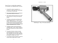
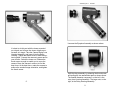
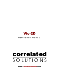
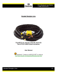
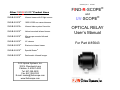
85643M_Rev. 1 09/2007
Other FIND-R-SCOPE® Product Lines
®
FIND-R-SCOPE
Infrared viewer with IR light source.
FIND-R-SCOPE®
1800 & 2200 nm camera/viewers.
FIND-R-SCOPE®
Infrared video system & monitor.
FIND-R-SCOPE
®
Helmet mounted infrared viewer.
FIND-R-SCOPE®
Microscope mounted infrared
viewer.
FIND-R-SCOPE®
UV viewers
®
FIND-R-SCOPE
Electronic infrared viewer
FIND-R-SCOPE®
Speckle Buster®
FIND-R-SCOPE®
Radiometric Infrared Imager
FJW Optical Systems, Inc.
322 N. Woodwork Lane
Palatine, IL 60067-4933
Tel: 847-358-2500
Fax: 847-358-2533
E-mail: [email protected]
www.findrscope.com
FIND-R-SCOPE®
and
UV-SCOPE®
OPTICAL RELAY
User’s Manual
For Part # 85643
85643M_Rev. 1 09/2007
Several things to consider before coupling the
CCD camera to your FIND-R-SCOPE® IR viewer:
1. It is best if the viewer is supported, i.e.,
mounted on a rigid object, like a sturdy tripod
or mounted on an optical table.
2. The viewer should be focused on a target producing a clear image on the screen.
3. Care should be taken that the focus is not disturbed during the mounting of the relay and
camera.
4. The Relay may be used to couple any video
camera equipped with a “C” or a “CS” lens
mounts. (If the camera has a “CS” mount then
a 5 mm extension ring must be inserted into
the “CS” mount.) The relay interfaces with the
viewer at the eyepiece mounting threads, and
with the camera at the lens “C” mount.
Find-R-Scope® , Relay, CCD camera assembly.
5. The Relay may be used with the following
FIND-R-SCOPE® viewers: 84499A, 84499 series, 85100, 85300 the UV Scope, 85100A, &
84530A.
6. The heavier of the two: viewer or camera,
should be supported or mounted on a rigid
body. The lighter of the two is then supported
via the Relay Assembly. The Relay Assembly
will support the weight of the viewer.
7. The following procedure describes mounting a
camera which is lighter than the viewer.
1.
6.
85643M_Rev. 1 09/2007
Unscrew the Eyepiece Assembly as shown above.
It is best to do this part with the viewer mounted
on a tripod, and to have the viewer objective prefocused at a target. Take the Camera-Relay Lens
Housing Assembly, and insert it into the Relay
Housing. Tighten the thumb screw to hold the system together. Connect the camera to power and to
your monitor. Switch the viewer on. Release the
thumb screw enough to enable you to move the
camera. Move the camera in and out to find the
best focus. At the best focus, rotate the camera to
achieve the needed image orientation, and tighten
the thumb screw.
5.
Split the relay assembly by releasing the thumb screw
and pulling the two assemblies apart as shown above.
The smaller diameter component, on the left, is the
relay Lens Housing Assembly. The larger one, on the
right, is the Relay Housing Assembly
2.
85643M_Rev. 1 09/2007
Take the relay housing, insert it into the eyepiece opening collapsing the spring, and screw it in, in place of the eyepiece.
Take your CCD camera and remove the lens. (If your camera has
the CS mount, and the C-mount adapter ring comes off with the
lens, unscrew the ring from the lens and screw it back into the camera lens mount.) Take the relay lens housing and screw it into the
camera lens mount.
Camera and Relay Lens Housing assembly
Assembly of the viewer and relay housing.
3.
4.