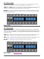
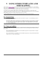
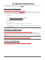
1
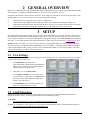
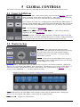
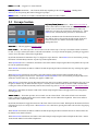
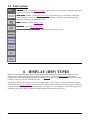
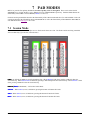
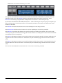
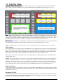
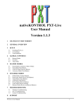
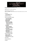
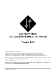
nativeKONTROL MXT-Live
User Manual
Version 1.0.3
1
CHANGES IN THIS VERSION
2
GENERAL OVERVIEW
3
SETUP
3.1
3.2
Live Settings
UserPreferences
4
LAYOUT OVERVIEW
5
GLOBAL CONTROLS
5.1
5.2
5.3
5.4
5.5
Upper Left Buttons
Master Section
Groups Section
Transport Section
Pads Section
6
DISPLAY (DSP) TYPES
7
PAD MODES
7.1
7.2
7.3
7.4
8
Session Mode
Clip Play Mode
Note Mode
Navigation Mode
ENCODER MODES
8.1
8.2
8.3
8.4
8.5
8.6
9
Global Mode
Track Mode
Clip Mode
Device Mode
Drum Mode
MIDI Mode
USING OTHER TEMPLATES AND MIDI MAPPING
9.1
9.2
10
10.1
10.2
10.3
11
General Notes
Notes on Conflicts
TROUBLESHOOTING
General Troubleshooting
Windows Troubleshooting
OS X Troubleshooting
SUPPORT
MXT-Live User Manual
1
1 CHANGES IN THIS VERSION
-
Updated for compatibility with Live 9.1.3 and beyond.
-
Added Live 9.5.1-compatible installers.
-
Fixed issue where performing certain tasks (such as switching to Note Mode) could turn off Record Quantization.
-
Other minor fixes/improvements.
NOTES: If you’ve modified your UserPreferences.txt file and don’t want to lose your changes, back up the file BEFORE
installing the new version of MXT-Live. After installing, copy the text you don’t want to lose from the UserPreferences.txt
file you backed up into the allotted space in the new UserPreferences.txt file that the installer will install.
MXT-Live User Manual
2
2 GENERAL OVERVIEW
MXT-Live is a MIDI Remote Script, Maschine MK2 template and MT Player preset for Native Instruments Maschine MK2
and Ableton Live 9 that turns the Maschine MK2 into a very powerful control surface for Live 9.
In addition to this manual, a control reference (MXT-Live Control Reference.pdf) and Live Lesson are also provided. After
installing MXT-Live, you can access the Live Lesson by using the following steps:
1.
2.
3.
4.
Show Help View by selecting Help View from Live’s Help menu.
Click the home button (rightmost button at the top of Help View) to return to the front page of Help View.
Scroll down to the bottom of Help View and click the Show all built-in lessons link to show the Table of Contents.
Scroll down to the bottom of the Table of Contents where you’ll find the MXT-Live Lesson section.
3 SETUP
The initial installation and setup for MXT-Live is covered in the provided MXT-Live Install Info documents. Please refer to
these documents for information on initial installation and setup. This section covers the settings you will need to make in
Live in order to use MXT-Live and also provides information on optional settings. Please take your time when completing
these steps. If you should run into trouble when performing any of these steps, please refer to the Troubleshooting section.
NOTE: In order to use MXT-Live, you need to have MT Player running and the MXT-Live preset selected in MT Player.
You also need to have the Maschine MK2 in MIDI Mode (accessed via SHIFT + CONTROL) and the MXT-Live template
selected on the Maschine MK2. Finally, in order to see the information that MXT-Live writes to the Display, you need to
select the Knob Display (via SHIFT + DISPLAY BUTTON 5).
3.1 Live Settings
The following settings will be found in Live’s Preferences on the MIDI/Sync tab. All of the settings listed here are required
for proper functionality of MXT-Live.
1.
Under MIDI Ports, turn off all of the
Track/Sync/Remote switches related to the Maschine
MK2. Also, turn off all of the Track/Sync/Remote
switches related to MT Player ports.
2.
Select MXT_Live as a Control Surface.
3.
For the Input and Output, select From MT Player 1
and To MT Player 1 respectively. On Windows, these
ports may be listed with a number preceding them
such as 2-From MT Player 1.
4.
Under MIDI Ports, turn on the Track switches for
MXT_Live Input and MXT_Live Output.
3.2 UserPreferences
MXT-Live includes a UserPreferences.txt file that allows you to change some of its default behaviors and includes
instructions on how to edit it. You can typically find this file in the following location:
On Windows:
- ProgramData\Ableton\Live 9\Resources\MIDI Remote Scripts\MXT_Live
On OS X, go to Applications, find Ableton Live 9.app, right-click and select Show Package Contents and then navigate to:
- Contents/App-Resources/MIDI Remote Scripts/MXT_Live
MXT-Live User Manual
3
4 LAYOUT OVERVIEW
The image below shows the layout of controls in MXT-Live. We’ve done our best to layout controls intuitively and to use
controls that are labeled on the Maschine MK2 in ways that directly relate the control’s label. For example, in the image
below you can see that the buttons labeled PLAY and DUPLICATE on the controller are also labeled PLAY and DUPLICATE
in the image below. When referring to controls of this sort, we will simply refer to controls by their label such as PLAY or
DUPLICATE.
However, some exceptions had to be made. For example, the button labeled CONTROL on the controller is labeled as DSP
TYPE in the image below. When referring to controls of this sort, we will refer to the label of the control in MXT-Live
followed by the label of the control on the controller such as DSP TYPE(CONTROL).
In the image below, the buttons shown in dark gray are not used by MXT-Live. The controls labeled in Blue text are
modifiers, which modify the function of other controls. And the controls without labels change depending on the selected
DSP Type, Pad Mode and/or Encoder Mode.
MXT-Live User Manual
4
5 GLOBAL CONTROLS
This section covers Global Controls, which are controls that function the same in all Modes unless otherwise noted.
5.1 Upper Left Buttons
DSP TYPE(CONTROL) – When pressed quickly, toggles between the DSP Types. When held
down, momentarily switches to the opposing DSP Type. When SHIFT(ENTER) is held down,
pressing this button will refresh all of the controller’s LEDs and displays.
This is useful in cases where you’re switching between different Maschine MK2 templates or
switching between Maschine MK2’s default functionality and MIDI Mode, either of which can
cause the controller’s LEDs and DISPLAY to become out of sync. Refresh will resolve this.
STEP – This only applies to Pad Note Mode.
ENC(BROWSE), ENC
ENC(SAMPLING) and ENC CTRL(ALL) – These function differently
depending on the selected Encoder Mode.
AUTOMAT(AUTO WR.) – By default, toggles Automation. Holding down SHIFT(ENTER) and
pressing this button will re-enable automation that has been overridden. Holding down ERASE
and pressing this button will clear any recorded automation from the selected Clip.
5.2 Master Section
JOG WHEEL – This controls different parameters/settings
depending on which other buttons are turned on/pressed. Pressing
this control will reveal the name of the parameter/setting it’s
controlling as well as its current value. You can also turn the
control while it is pressed.
VOLUME – When turned on, the JOG WHEEL will be assigned to
control Master Volume. Holding down SHIFT(ENTER) will assign
the JOG WHEEL to Cue Volume.
QUANTIZE(SWING) – When turned on, the JOG WHEEL will be assigned to control Global Quantization. Holding down
SHIFT(ENTER) will assign the JOG WHEEL to Record Quantization. This button also serves a couple of other purposes. It
functions as a modifier, which modifies the function of other controls. Also, when held down and DSP Type is set to
Encoder, it sets up ENCODERS 1 – 3 to adjust Quantization settings.
DISPLAY with DSP Type set to Encoder and Quantize(SWING) held down.
TEMPO – When turned on, the JOG WHEEL will be assigned to control Tempo in 1-BPM increments. Holding down
SHIFT(ENTER) will assign the JOG WHEEL to control Tempo in 0.1-BPM increments.
UNDO(MASTER) – Triggers Live’s Undo function.
MXT-Live User Manual
5
REDO(MASTER) – Triggers Live’s Redo function.
REPEAT/RATE
REPEAT/RATE(NOTE REPEAT) – This functions differently depending on the selected Pad Mode. Holding down
SHIFT(ENTER) and pressing this button will trigger Tap Tempo.
SHIFT(ENTER) – Functions as a modifier, which modifies the function of other controls.
5.3 Groups Section
UP/LEFT/DOWN/RIGHT(B,E,F,G) – When Pad Session Mode is
selected, these buttons use Blue LEDs (as shown) and move the grid
selector in Live to select the Tracks and Scenes to control. By
default, they will move the grid selector in increments of 1. When
SHIFT(ENTER) is held down, they will move in increments of 4.
When any Pad Mode aside from Pad Session Mode is selected,
these buttons will use Green LEDs and will navigate Tracks and
Scenes in Session View and the insert marker and Tracks in
Arrangement View.
SUSTAIN(A) – This only applies to Pad Note Mode.
CLIP CTRL(C) – This button provides various control over the selected Clip. If no Clip is selected, the button’s LED will
be dark. If a Clip is selected, the button’s LED will be dim White. If a Clip is selected and playing, recording or triggered in
Session View, the button’s LED will be bright White.
By default, this button will launch the Clip if it’s stopped or stop it otherwise. When SHIFT(ENTER) is held down, pressing
this button will immediately launch or stop the Clip (without quantization).
When QUANTIZE(SWING) is held down, the button’s LED will be Amber and pressing the button will quantize the Clip with
the current quantization settings.
When ERASE is held down, the button’s LED will be Red and pressing the button will delete the Clip. Deleting only applies
to Session View.
When DUPLICATE is held down, the button’s LED will be Purple and pressing the button will duplicate the Clip.
Duplicating only applies to Session View. When DUPLICATE and SHIFT(ENTER) are held down, pressing the button will
double the contents of the Clip. Doubling only applies to MIDI Clips.
When SELECT is held down, pressing this button will lock on to the Clip (so that it continues controlling the Clip even if you
navigate to another Clip) or unlock from the Clip if it’s currently locked. When locked, the button’s LED will flash White.
Locking also affects all other functionality related to the selected Clip (such as Encoder Clip Mode and Pad Clip Play Mode).
When MUTE is held down, the button’s LED will be Yellow and pressing the button will toggle between activating and deactivating the Clip.
TRACK CTRL(H) – This button provides various control over the selected Track. If the selected Track can be armed, the
button’s LED will be dim Red unless the Track is armed in which case the LED will be bright Red. If the Track cannot be
armed, this button’s LED will be dark.
By default, this button will toggle the Arm state of the Track if the Track can be armed. Holding down the button will fold or
unfold the Track (if it is a Group Track). When SHIFT(ENTER) is held down, pressing this button will select the Clip playing
on the Track.
When ERASE is held down, the button’s LED will be Red and pressing the button will delete the Track. Return Tracks and
the Master Track cannot be deleted.
When DUPLICATE is held down, the button’s LED will be Purple and pressing the button will duplicate the Track. Return
Tracks and the Master Track cannot be duplicated.
MXT-Live User Manual
6
When SELECT is held down, pressing this button will lock on to the Track (so that it continues controlling the Track even if
you navigate to another Track) or unlock from the Track if it’s currently locked. When locked, the button’s LED will flash
White or Red if the Track is armed. Locking also affects all other functionality related to the selected Track (such as Encoder
Track Mode).
When SOLO is held down, the button’s LED will be Blue and pressing the button quickly will toggle the Solo state of the
Track. If the button is held down, it will momentarily toggle the Solo state of the Track.
When MUTE is held down, the button’s LED will be Yellow and pressing the button quickly will toggle the Mute state of the
Track. If the button is held down, it will momentarily toggle the Mute state of the Track.
5.4 Transport Section
RESTART – Reverts to Arrangement position 1.1.1. When
SHIFT(ENTER) is held down, pressing this button will trigger Back
to Arrangement.
RWD(TRANSPORT)/FFW(TRANSPORT)– Rewind or fast-forward.
When SHIFT(ENTER) is held down, pressing these buttons will
nudge Live’s tempo down or up.
FIX LEN(GRID) – Toggles Fixed Length recording. When held down, the DISPLAY will show the Fixed Length to use and
this can be adjusted with the JOG WHEEL. When SHIFT(ENTER) is held down, pressing this button will select the next
available Clip Slot on the selected Track for recording. This will create a new Scene if necessary.
DISPLAY when FIX LEN(GRID) pressed.
PLAY – Toggles playback and also functions as a visual metronome that flashes in sync with Live’s tempo. When
SHIFT(ENTER) is held down, pressing this button will toggle the Metronome state.
REC – In Session View, triggers Fixed Length recording (if FIX LEN(GRID) is on) or toggles Session Record/Overdub. In
Arrangement View, toggles Arrangement Overdub. When SHIFT(ENTER) is held down, pressing this button will toggle
Arrangement Record.
ERASE – Modifies the function of other controls.
MXT-Live User Manual
7
5.5 Pads Section
SESSION(SCENE) – Selects Pad Session Mode. When SHIFT(ENTER) is held down, pressing this button will
toggle between Session and Arrangement View.
CLIP PLAY(PATTERN) – Selects Pad Clip Play Mode. When SHIFT(ENTER) is held down, pressing this
button will toggle between Device and Clip View. When ERASE is held down, pressing this button will
toggle between showing and hiding Detail View.
NOTE(PAD MODE) – Selects Pad Note Mode.
NAVIGATE
NAVIGATE – Selects Pad Navigation Mode.
DUPLICATE/SELECT/SOLO/MUTE – Modify the function of other controls.
6 DISPLAY (DSP) TYPES
MXT-Live uses the Maschine MK2’s DISPLAY and DISPLAY BUTTONS (the 8 buttons above the DISPLAY) in two
primary ways; to display information about and control settings related to the selected Encoder Mode and to display
information about and control settings related to the selected Pad Mode. These two types of information display and settings
control are referred to as Encoder and Pad respectively.
By default, the Encoder type will be selected. When the DSP TYPE(CONTROL) button is on, the Pad type will be selected.
As mentioned in the Upper Left Buttons section, pressing this button quickly will toggle between the two types. Holding the
button down will momentarily switch to the opposing type. This allows you to, for example, have the Encoder type selected,
momentarily switch to the Pad type to change a setting and then switch back to the Encoder type.
MXT-Live User Manual
8
7 PAD MODES
MXT-Live provides four primary Pad Modes; Session, Clip Play, Note and Navigation. These can be selected with
SESSION(SCENE), CLIP PLAY(PATTERN), NOTE(PAD MODE) and NAVIGATE respectively. Each Pad Mode dictates the
functionality of the PADS as well as REPEAT/RATE(NOTE REPEAT).
Each sub-section presented here describes the functionality of the controls mentioned above for each Pad Mode. Each subsection also describes the information shown in the DISPLAY as well as the functionality of the DISPLAY BUTTONS for
each Pad Mode when DSP Type is set to Pad.
7.1 Session Mode
Session Mode allows you to launch Clips across 4 Tracks and 4 Scenes at a time. The Tracks and Scenes being controlled
will be indicated by a grid selector (colored border).
PADS – By default, the PADS are used for launching Clips. When ERASE is held down, pressing a PAD will delete the
associated Clip. When DUPLICATE is held down, pressing a PAD will duplicate the associated Clip. When SELECT is held
down, pressing a PAD will select the associated Clip.
REPEAT/RATE
REPEAT/RATE(NOTE REPEAT) – No function in this Mode.
SELECT – When SHIFT(ENTER) is held down, pressing this button will unarm all Tracks.
SOLO – When SHIFT(ENTER) is held down, pressing this button will unsolo all Tracks.
MUTE – When SHIFT(ENTER) is held down, pressing this button will unmute all Tracks.
MXT-Live User Manual
9
DISPLAY in Session Mode with DSP Type set to Pad.
The upper line of the DISPLAY shows the functions available from the DISPLAY BUTTONS. By default, SCENE will
launch the selected Scene. When ERASE is held down, pressing this button will delete the selected Scene. When
DULICATE is held down, pressing this button will duplicate the selected Scene. STPLL will stop all Clips.
By default, the last 4 DISPLAY BUTTONS (labeled STOP1 – STOP4 in the image on the previous page) will stop the Clips
that are playing on the 4 Tracks being controlled. The functionality and labels of these buttons will change when certain
modifiers are held down.
When ERASE is held down, these buttons can be used for deleting the 4 Tracks being controlled.
When DUPLICATE is held down, these buttons can be used for duplicating the 4 Tracks being controlled.
When SELECT is held down, these buttons can be used for selecting the 4 Tracks being controlled. If a Track is already
selected, pressing the associated button will toggle the Arm state of the Track. Holding down a button will fold or unfold the
associated Track (if it is a Group Track).
When SOLO is held down, these buttons can be used for soloing the 4 Tracks being controlled. If pressed quickly, they will
toggle the Solo state of the associated Track. If held down, they will momentarily toggle the Solo state of the associated
Track.
When MUTE is held down, these buttons can be used for muting the 4 Tracks being controlled. If pressed quickly, they will
toggle the Mute state of the associated Track. If held down, they will momentarily toggle the Mute state of the associated
Track.
The lower line of the DISPLAY shows the name of the 1st Scene and 1st Track being controlled.
MXT-Live User Manual
10
7.2 Clip Play Mode
Clip Play Mode allows you to play/adjust the selected Clip in several ways. This Mode is comprised of four Sub-Modes
(DEF, CHOP, LOOP and CHRM) that can be selected with the DISPLAY BUTTONS when DSP Type is set to Pad.
PADS when DEF is selected.
PADS when CHRM is selected.
PADS – When the DEF Sub-Mode is selected, the upper 8 PADS are assigned to Clip Chopping (described below) and the
lower 8 PADS are assigned to Clip Loop Control (described below). When the CHOP Sub-Mode is selected, all 16 PADS are
assigned to Clip Chopping. When the LOOP Sub-Mode is selected, all 16 PADS are assigned to Clip Loop Control. When
the CHRM Sub-Mode is selected, all 16 PADS are assigned to Chromatic Clip Play (described below).
REPEAT/RATE
REPEAT/RATE(NOTE REPEAT) – When held down, assigns the first four DISPLAY BUTTONS to select the Quantization to
use for launching/re-launching Clips in this Mode. This is only accessible when DSP Type is set to Pad.
NOTE: The Quantization functionality will only work correctly with Clips whose Launch Quantization is set to Global.
Clip Chopping
Clip Chopping allows you to Chop Clips up. Each PAD used for Clip Chopping will be assigned to evenly distributed Start
positions based on the Clip’s length. For Clips that are Looping, the length will be based on the Clip’s Loop Start and End
Marker. For Clips that aren’t Looping, the length will be solely based on the Clip’s End Marker. Pressing a PAD used for
Clip Chopping will move the Clip’s Start Marker to the corresponding position and re-launch the Clip.
When ERASE is held down, pressing a PAD used for Clip Chopping will re-align the playing position of the Clip with the
playing position of Live.
NOTES: Clip Chopping will not work correctly with Clips whose Launch Quantization is set to None. Clip Chopping will
not allow the Clip’s Start Marker to be moved to a position that is less than 1/16th note away from the Clip’s Loop End or
End Marker. The process of moving a Clip’s Start Marker and re-launching is a bit more resource-dependent than just
launching a Clip. For that reason, it is possible to experience hard disk overloads and/or audio drop outs when Chopping
Clips. You may be able to offset this by activating the Clip’s RAM button and/or increasing the Quantization to use.
Clip Loop Control
Clip Loop Control allows you to select the Clip’s Loop size and position. Each PAD used for Clip Loop Control will set the
Loop to the same size at evenly distributed positions based on the Clip’s length. This supports multiple PAD presses to allow
for different sizes to be set.
Chromatic Clip Play
Chromatic Clip Play allows the PADS to play Audio or MIDI Clips chromatically. This will only work correctly on MIDI
Clips if the Track the MIDI Clip is on contains a Pitch MIDI Effect that is not inside of a Rack. The PADS will control the
Pitch parameter of the first Pitch MIDI Effect on the Track.
MXT-Live User Manual
11
Default DISPLAY in Clip Play Mode with DSP Type set to Pad.
The upper line of the DISPLAY shows the functions available from the DISPLAY BUTTONS. LOOP will toggle the Clip’s
Loop on/off. When SHIFT(ENTER) is held down, pressing this button will reset the Clip’s Loop (move its Start and End to
the Clip’s Start and End Markers respectively). DEF/CHOP/LOOP/CHRM select the Sub-Mode to use. When CHRM is
selected, an additional function (labeled LEGAT) will be accessible. LEGAT enables/disables Legato Clip launching. When
enabled, the Clip’s Launch Mode will be ignored and launching will function as if the Trigger Launch Mode was selected.
The lower line of the DISPLAY shows the name of the selected Track and selected Clip.
DISPLAY in Clip Play Mode with DSP Type set to Pad and REPEAT/RATE(NOTE REPEAT) held down.
The functionality and information shown here is the same as noted above except that the first four DISPLAY BUTTONS
(1/4 – 1/32) are used for selecting the Quantization to use for launching/re-launching Clips in this Mode
MXT-Live User Manual
12
7.3 Note Mode
Note Mode allows you to play, edit and sequence Notes in a variety of ways. This Mode is comprised of two Sub-Modes
(Drum and Scale) that will be selected automatically depending on whether the selected Track contains a Drum Rack/Impulse
device or not. This Mode also includes a Super-Mode (Sequence) accessible from either Sub-Mode that you can toggle
on/off by pressing STEP.
This Mode can operate on Note Lanes in the selected MIDI Clip. A Note Lane is a horizontal row of Notes in a MIDI Clip.
For example, all of the C1 Notes in a MIDI Clip make up one Note Lane, all of the D#2 Notes make up another Note Lane.
7.3a Sequence Super-Mode
Sequence Super-Mode allows you to step-sequence into the selected MIDI Clip. This Super-Mode can be toggled on/off by
pressing STEP. This Super-Mode can be used in conjunction with the Encoder Note Edit Sub-Mode, which will allow you to
easily edit Steps as they are added or selected.
PADS when REPEAT/RATE(NOTE REPEAT) is off.
PADS when REPEAT/RATE(NOTE REPEAT) is on.
PADS – By default, the PADS will add/remove Steps in the Note Lane associated with the last PAD that was played in the
Drum or Instrument Sub-Modes. The position and length of added Steps is determined by the selected Resolution (described
on the next page). The velocity of added Steps is determined by the selected Velocity Type (described on the next page).
When SELECT is held down, the PADS can be used for selecting Steps to edit with the Encoder Note Edit Sub-Mode. In the
case of the Event Edit Sub-Mode, single Steps will be selected. In the case of the Range Edit Sub-Mode, ranges can be
selected by pressing the first Step in the range and then pressing the last Step in the range.
When MUTE is held down, the PADS can be used for muting/unmuting Steps or inserting muted Steps.
The Steps will be added/removed/selected/muted within the selected Edit Position.
When REPEAT/RATE(NOTE REPEAT) is on, the upper 8 PADS are used to select the Edit Position, which is the portion of the
Clip that you will edit. This supports multiple PAD presses to allow for an Edit Position range to be selected. When
SHIFT(ENTER) is held down, these PADS will select the Edit Position and Loop Position. When ERASE is held down, these
PADS will delete all the Steps within the associated Edit Position or Edit Position range. The lower 8 PADS select the Loop
Position, which is the portion of the Clip that will Loop. This supports multiple PAD presses to allow for a Loop Position
range to be selected. In both cases, each PAD represents one sequencer page. The length of a sequencer page is determined
by the selected Resolution.
REPEAT/RATE
REPEAT/RATE(NOTE REPEAT) – Toggles the function of the PADS between Step editing and Edit/Loop Position selection.
MXT-Live User Manual
13
DISPLAY in Sequence Super-Mode with DSP Type set to Pad and REPEAT/RATE(NOTE REPEAT) off.
The upper line of the DISPLAY shows the functions available from the DISPLAY BUTTONS. PAD – and PAD + will
navigate between PADS to step-sequence. The rest of these buttons select the Velocity Type, which determines the velocity
to use when adding Steps.
INPUT will set the velocity of Steps to be equal to the velocity at which the associated PAD was pressed. RANDM will set
the velocity of Steps to a random value where the highest value in the range is set by the buttons to the right (the lowest value
in the range will be 27 less than the highest value). 46, 73, 100 and 127 set the velocity to a fixed value (unless RANDM is
on).
The lower line of the DISPLAY shows the name of the Note (or Drum Rack/Impulse Pad) being sequenced, the current Edit
Position and the name of the selected Clip.
DISPLAY in Sequence Super-Mode with DSP Type set to Pad and REPEAT/RATE(NOTE REPEAT) on.
The information shown here is the same as noted above except that the DISPLAY BUTTONS (1/4 – 1/32T) are used for
selecting the Resolution to use for sequencing.
NOTE: When a triplet Resolution (such as 1/8T) is selected, the last column of PADS is not usable. The LEDs of these
PADS will be dim Red to indicate this.
7.3b Functionality Common to Sub-Modes
Both of the Note Mode Sub-Modes share some of the same functionality.
PADS – By default, the PADS send out Notes for playing instruments/recording MIDI data into MIDI Clips. The last PAD
that was played will be selected for sequencing in the Sequence Super-Mode (described in the previous section). Each PAD
can also edit the Note Lane in the selected MIDI Clip associated with the Note the PAD sends.
When QUANTIZE is held down, the LEDs of the PADS will either be dark (to indicate that the associated Note Lane is
empty) or Amber (to indicate that the associated Note Lane is not empty). Pressing a PAD will quantize the Note Lane with
the current quantization settings.
When ERASE is held down, the LEDs of the PADS will either be dark (to indicate that the associated Note Lane is empty) or
Red (to indicate that the associated Note Lane is not empty). Pressing a PAD will delete the associated Note Lane (if the Clip
is not playing) or erase the portion of the Note Lane that the playhead is currently passing over (if the Clip is playing).
When SOLO is held down, the LEDs of the PADS will either be dark (to indicate that the associated Note Lane is empty), dim
Blue (to indicate that the associated Note Lane is not soloed) or bright Blue (to indicate that the associated Note Lane is
soloed). Pressing a PAD will solo the associated Note Lane.
MXT-Live User Manual
14
When MUTE is held down, the LEDs of the PADS will either be dark (to indicate that the associated Note Lane is empty),
bright Yellow (to indicate that the associated Note Lane contains no muted Notes) or dim Yellow (to indicate that the
associated Note Lane contains muted Notes). Pressing a PAD will mute the associated Note Lane. Holding down
SHIFT(ENTER) and pressing MUTE will unmute all Note Lanes.
REPEAT/RATE
REPEAT/RATE(NOTE REPEAT) – Toggles Note Repeat on/off. When on and DSP Type is set to Pad, the DISPLAY
BUTTONS can be used for selecting the Note Repeat rate.
7.3c Drum Sub-Mode
Drum Sub-Mode provides a dedicated interface for playing/controlling either a Drum Rack or Impulse device on the selected
Track.
PADS when playing/controlling a Drum Rack.
PADS when playing/controlling an Impulse device.
PADS – The PADS are used for playing the visible Pads in the Drum Rack or the Impulse device on the selected Track. The
PADS also provide the functionality mentioned in Functionality Common to Sub-Modes.
In the case of Drum Racks, the PADS offer some additional functionality. When SELECT is held down, pressing a PAD will
select the associated Drum Rack Pad. When SELECT and SOLO are held down, pressing a PAD will solo the associated
Drum Rack Pad. When SHIFT(ENTER) and SELECT are held down, pressing SOLO will unsolo all Drum Rack Pads.
When SELECT and MUTE are held down, pressing a PAD will mute the associated Drum Rack Pad. When SHIFT(ENTER)
and SELECT are held down, pressing MUTE will unmute all Drum Rack Pads.
DISPLAY in Drum Sub-Mode with DSP Type set to Pad.
The upper line of the DISPLAY shows the functions available from the DISPLAY BUTTONS. DR POS – and DR POS +
will move the Drum Rack’s Selector down/up, which selects the visible Pads that will be playable/controllable. By default,
these will move in increments of 4 rows. When SHIFT(ENTER) is held down, they will move in increments of 1 row. FULL
will toggle (if pressed quickly) or momentarily activate (if held down) Full Velocity for the PADS.
The lower line of the DISPLAY shows the name of the drum device being controlled as well as the name of the selected Clip.
MXT-Live User Manual
15
7.3d Scale Sub-Mode
Scale Sub-Mode provides access to a variety of Scale Types as well as the ability to Capture Notes from MIDI Clips.
PADS when assigned to a built-in Scale Types.
PADS when assigned to Captured Notes.
PADS – The PADS are used for playing the Notes of one of the built-in Scale Types or Notes that were Captured from a
MIDI Clip. The PADS also provide the functionality mentioned in Functionality Common to Sub-Modes.
SUSTAIN(A) – This button functions like a Sustain Pedal. This is the only part of MXT-Live that uses this button. The
button’s LED will be purple when Scale Sub-Mode is selected.
DISPLAY in Scale Sub-Mode with DSP Type set to Pad.
The upper line of the DISPLAY shows the functions available from the DISPLAY BUTTONS. OCT – and OCT + will scroll
down/up by 1 Octave. When SHIFT(ENTER) is held down, OCT – and OCT + will scroll down/up by 1 Semitone.
ROOT – and ROOT + will move down/up between Root Notes. These buttons will not be accessible when the PADS are
assigned to Captured Notes. TYPE – and TYPE + will move down/up between Scale Types. CAP will capture the first 16
unique Notes from the selected MIDI Clip and assign them to the PADS in Note order. If more than 16 unique Notes have
been captured, you can scroll between them by holding down SHIFT(ENTER) and using OCT – and OCT +. FULL will
toggle (if pressed quickly) or momentarily activate (if held down) Full Velocity for the PADS.
The lower line of the DISPLAY shows the name of the current Root Note and Scale Type as well as the name of the selected
Clip. If the PADS are assigned to Captured Notes, the name of the Clip the Notes were Captured from will be displayed
instead of the Root Note and Scale Type. Also, upon changing any of the settings mentioned above, the Note range of the
PADS will momentarily be shown in the DISPLAY.
MXT-Live User Manual
16
7.4 Navigation Mode
Navigation Mode allows for sending keystrokes/shortcuts as well as triggering ClyphX Action Lists.
PADS – The PADS send the keystrokes/shortcuts shown above. These are self-explanatory except for PAD 13 – PAD 15.
These PADS are used to move the Focus to different sections of Live’s window (the Browser section, the Main section of the
window and the Detail View section) so that the section can be controlled via keystrokes/shortcuts.
REPEAT/RATE
REPEAT/RATE(NOTE REPEAT) – No function in this Mode.
DISPLAY in Navigation Mode with DSP Type set to Pad
and Key Assignments selected.
DISPLAY in Navigation Mode with DSP Type set to Pad
and ClyphX Assignments selected.
The DISPLAY BUTTONS can send keystrokes/shortcuts or trigger ClyphX Action Lists. You can toggle between these sets
of functions by pressing NAVIGATE.
In both cases, the upper line of the DISPLAY shows the names of the keystrokes/shortcuts or ClyphX Action Lists assigned
to the DISPLAY BUTTONS. If a button has no keystroke/shortcut assignment or ClyphX Action List assignment, the
button’s LED will be dark and the associated section of the DISPLAY will be blank.
You can specify the keystrokes/shortcuts to send and ClyphX Action Lists to trigger in your UserPreferences file.
NOTE: In order to trigger ClyphX Action Lists in this Mode, ClyphX needs to be installed and selected as a Control Surface.
You can download and learn more about ClyphX here: http://beatwise.proboards.com/board/5/clyphx
MXT-Live User Manual
17
8 ENCODER MODES
MXT-Live provides six primary Encoder Modes; Global, Track, Clip, Device, Drum and MIDI. These can be selected
when DSP Type is set to Encoder by holding down SELECT and using the first six DISPLAY BUTTONS.
DISPLAY with DSP Type set to Encoder and SELECT held down.
Each Encoder Mode dictates the functionality of the ENCODERS as well as ENC(BROWSE), ENC(SAMPLING) and ENC
CTRL(ALL).
Each sub-section presented here describes the functionality of the controls mentioned above for each Encoder Mode. Each
sub-section also describes the functionality of the DISPLAY BUTTONS for each Encoder Mode when DSP Type is set to
Encoder.
Additional Parameter Control
Encoder Modes that control device or mixer parameters (Track, Device and Drum in particular) utilize the DISPLAY
BUTTONS for additional parameter control.
By default, the DISPLAY BUTTONS allow for proper automation recording. When pressed, Live is informed to start
recording automation for the parameter assigned to the associated ENCODER. When released, Live is informed to stop
recording automation from the parameter assigned to the associated ENCODER. This allows automation to be recorded
without overwriting existing automation.
When SHIFT(ENTER) is held down, the DISPLAY BUTTONS reset or toggle the value of the parameter assigned to the
associated ENCODER. The button LEDs will be lit if resetting or toggling is possible.
When ERASE is held down, the DISPLAY BUTTONS clear automation that has been recorded for the parameter assigned to
the associated ENCODER. If you’re using Live 9.1 or later, the button LEDs will be lit if clearing automation is possible.
Otherwise, the buttons LEDs will be dark.
MXT-Live User Manual
18
8.1 Global Mode
Global Mode controls global settings.
ENCODER 1 – Rewinds/fast-forwards by 1 Beat or 1 Bar if SHIFT(ENTER) is held down.
ENCODER 2 – Navigates between Arrangement Locators. When SHIFT(ENTER) is held down, turning ENCODER 2 will
add a Locator at the current position or delete the Locator at the current position if one exists.
ENCODER 3 and ENCODER 4 – Adjust Arrangement Loop Start and Length by 1 Beat or 1 Bar if SHIFT(ENTER) is held
down.
ENCODER
ENCODER 5 – Turns Arrangement Loop on/off.
ENCODER 6 – Zooms horizontally in Arrangement View or navigates Tracks in Session View.
ENCODER 7 – Zooms the selected Track vertically in Arrangement View or navigates Scenes in Session View. When
SHIFT(ENTER) is held down, turning ENCODER 7 will vertically zoom all Tracks in Arrangement View.
ENCODER 8 – Adjusts Global Groove Amount.
ENC(BROWSE) and ENC
ENC(SAMPLING) – Toggle Punch In and Out respectively.
ENC CTRL(ALL) – No function in this Mode.
DISPLAY in Global Mode with DSP Type set to Encoder.
DISPLAY BUTTONS – No function in this Mode.
MXT-Live User Manual
19
8.2 Track Mode
Track Mode controls parameters/settings of the selected Track. This Mode is comprised of two Sub-Modes (Default and I/O)
that can be selected with the ENC(BROWSE) and ENC(SAMPLING) respectively.
ENC(BROWSE) and ENC
ENC(SAMPLING) – Select the Default and I/O Sub-Modes respectively.
ENC CTRL(ALL) – No function in this Mode.
8.2a Default Sub-Mode
In the Default Sub-Mode, the ENCODERS provide control over the Track’s Volume, Pan and its first 5 Sends. By default, the
ENCODERS offer relatively coarse adjustment. When SHIFT(ENTER) is held down, the ENCODERS offer finer adjustment.
DISPLAY in Default Sub-Mode with DSP Type set to Encoder.
DISPLAY
DISPLAY BUTTONS – Provide Additional Parameter Control.
8.2b I/O Sub-Mode
In the I/O Sub-Mode, the ENCODERS provide control over the Track’s Input Routing, Input Sub-Routing, Output Routing,
Output Sub-Routing, Monitoring State and Crossfade Assignment.
DISPLAY in I/O Sub-Mode with DSP Type set to Encoder.
DISPLAY BUTTONS – No function in this Sub-Mode.
MXT-Live User Manual
20
8.3 Clip Mode
Clip Mode controls settings of the selected Clip. This Mode is comprised of two Sub-Modes (Default and Note Edit) that can
be selected with the ENC(BROWSE) and ENC(SAMPLING) respectively.
ENC(BROWSE) and ENC
ENC(SAMPLING) – Select the Default and Note Edit Sub-Modes respectively.
8.3a Default Sub-Mode
In the Default Sub-Mode, the ENCODERS provide control over the Clip’s Start/End Markers, Loop Start/End, Detune,
Transpose and Gain. By default, the ENCODERS offer relatively fine adjustment. When SHIFT(ENTER) is held down, the
ENCODERS offer coarser adjustment.
Adjustments of Start/End Markers and Loop Start/End are quantized. The quantization to use can be selected via
ENCODER 8.
ENC CTRL(ALL) – No function in this Sub-Mode.
DISPLAY in Default Sub-Mode with DSP Type set to Encoder.
DISPLAY BUTTONS – No function in this Sub-Mode.
NOTES: Detune, Transpose and Gain are only accessible to Audio Clips. Loop Start/End are only accessible for Clips that
are looping. Start Marker and Loop Start cannot be moved to a position less than 1.1.1. Loop End cannot be moved to a
position greater than the Clip’s End Marker.
8.3b Note Edit Sub-Mode
In the Note Edit Sub-Mode, the ENCODERS provide edit control over Note Events in MIDI Clips. By default, the
ENCODERS offer relatively fine adjustment. When SHIFT(ENTER) is held down, the ENCODERS offer coarser adjustment.
There are two Note Edit Sub-Modes (Event and Range) that you can toggle between by pressing ENC(SAMPLING).
NOTES: Pitch, Time and Length will not allow you to move Note Events to an occupied or partially occupied position/pitch.
Time and Length will not allow you to adjust Note Events such that they would extend past the Clip’s End. Time will not
allow you to move Note Events to a position less than 1.1.1.
The Note Edit Sub-Modes will select Notes in the MIDI Clip upon changes. However, some changes to a MIDI Clip can
cause the selection in the MIDI Clip to become out of sync with the selection(s) in the Note Edit Sub-Modes. This can be
rectified by pressing ENC(SAMPLING) twice.
8.3b1 Event Edit Sub-Mode
The Event Edit Sub-Mode allows you to edit one Note Event at a time.
ENCODER 1 – Selects the Note Event to edit.
ENCODER 2 – Adjusts the Pitch of the Note Event.
ENCODER 3 and ENCODER 4 – Adjust the Time and Length of the Note Event. These adjustments are quantized. The
quantization to use can be selected via ENCODER 8.
MXT-Live User Manual
21
ENCODER 5 – Adjusts the Velocity of the Note Event.
ENCODER 6 – Adjusts the Muted status of the Note Event.
ENCODER 7 – Selects the type of sorting to use (TIME or PITCH) to use when selecting Note Events with ENCODER 1.
ENCODER 8 – Selects the quantization to use when adjusting Note Event Time and Length.
ENC CTRL(ALL) – When SHIFT(ENTER) is held down, pressing this button will add a new Note Event. This will be added
after the selected Note Event if possible or will be added at the next Pitch up. When adding Note Events, it’s possible that
portions of existing Note Events will be overwritten. When ERASE is held down, pressing this button will delete the selected
Note Event.
DISPLAY in Event Edit Sub-Mode with DSP Type set to Encoder.
DISPLAY BUTTONS – No function in this Sub-Mode.
8.3b2 Range Edit Sub-Mode
The Range Edit Sub-Mode allows you edit ranges of Note Events.
ENCODER 1 and ENCODER 2 – Select the range of Note Event Pitches to edit.
ENCODER 3 and ENCODER 4 – Select the range of Note Event Times to edit.
ENCODER 6 – Selects the Note Event setting that ENCODER 7 will adjust.
ENCODER 7 – Adjusts the selected Note Event setting. Adjustments of Time and Length are quantized. The quantization to
use can be selected via ENCODER 8.
ENCODER 8 – Selects the quantization to use when adjusting Note Event Time and Length.
ENC CTRL(ALL) – When SHIFT(ENTER) is held down, pressing this button will select all Note Events. When ERASE is
held down, pressing this button will delete Note Events within the selected range.
DISPLAY in Range Edit Sub-Mode with DSP Type set to Encoder.
DISPLAY BUTTONS – No function in this Sub-Mode.
MXT-Live User Manual
22
8.4 Device Mode
In Device Mode, the ENCODERS control parameters of the selected Device. By default, the ENCODERS offer relatively
coarse adjustment. When SHIFT(ENTER) is held down, the ENCODERS offer finer adjustment.
ENC(BROWSE) and ENC
ENC(SAMPLING) – If the selected Device has more than 8 parameters, these will move between banks
of 8 parameters. If the selected Device is a Rack with Chains, these will move between the Device’s Chains. When
SHIFT(ENTER) is held down, these will navigate between Devices on the selected Track.
ENC CTRL(ALL) – Toggles the selected Device on/off. When SHIFT(ENTER) is held down, pressing this button will lock
to/unlock from the selected Device. When locked, the button’s LED will flash. When ERASE is held down, pressing this
button will delete the selected Device.
DISPLAY in Device Mode with DSP Type set to Encoder.
DISPLAY BUTTONS – Provide Additional Parameter Control.
8.5 Drum Mode
In Drum Rack Mode, ENCODERS 1-7 control mixer settings (Volume, Pan and the first 5 Sends) of the selected Drum
Rack Pad of the Drum Rack on the selected Track. By default, ENCODERS 1-7 offer relatively coarse adjustment. When
SHIFT(ENTER) is held down, ENCODERS 1-7 offer finer adjustment. ENCODER 8 scrolls between Drum Rack Pads by 1
or by 16 when SHIFT(ENTER) is held down. If necessary, this will also move the Drum Rack Selector so that the selected
Drum Rack Pad is visible.
ENC(BROWSE) – Toggles the selected Drum Rack Pad’s Mute switch if pressed quickly or momentarily toggles the Mute
switch if held down. When SHIFT(ENTER) is held down, pressing this button will unmute all Drum Rack Pads.
ENC
ENC(SAMPLING) – Toggles the selected Drum Rack Pad’s Solo switch if pressed quickly or momentarily toggles the Solo
switch if held down. When SHIFT(ENTER) is held down, pressing this button will unsolo all Drum Rack Pads.
ENC CTRL(ALL) – When ERASE is held down, pressing this button will delete the Drum Rack.
DISPLAY in Drum Mode with DSP Type set to Encoder.
DISPLAY BUTTONS – Provide Additional Parameter Control.
MXT-Live User Manual
23
8.6 MIDI Mode
MIDI Mode sends out common MIDI Control Change messages (CCs) and Program Change messages, which most MIDI
instruments respond to. By default, the ENCODERS offer coarse adjustment. When SHIFT(ENTER) is held down, the
ENCODERS offer finer adjustment.
ENCODER 1 – Sends out Volume (CC#7).
ENCODER 2 – Sends out Pan (CC#10).
ENCODER 3 – Sends out Filter Cutoff (CC#74).
ENCODER 4 – Sends out Filter Resonance (CC#71).
ENCODER 5 – Sends out Amp Envelope Attack (CC#73).
ENCODER 6 and ENCODER 7 – Send out Bank Select messages (CC#0 and CC#32). Turning either of these ENCODERS
will send out both the MSB and LSB value and will also send out a Program Change message with a value of 0. This is done
as most MIDI instruments require this sequence of messages in order to actually switch between banks.
ENCODER 8 – Sends out Program Change messages.
ENC(BROWSE) and ENC
ENC(SAMPLING) – Send out Program Change messages incrementally.
ENC CTRL(ALL) – No function in this Mode.
DISPLAY in MIDI Mode with DSP Type set to Encoder.
DISPLAY BUTTONS – No function in this Mode.
MXT-Live User Manual
24
9 USING OTHER TEMPLATES AND
MIDI MAPPING
When using the default Live settings for MXT-Live, it is not possible for other controllers/MIDI devices or other Maschine
MK2 templates to conflict with MXT-Live as MXT-Live has a direct line of communication with Live. However, the default
settings also prevent you from using other Maschine MK2 templates for MIDI mapping.
It is possible to use other Maschine MK2 templates for MIDI mapping while using MXT-Live, but this adds a bit of
complexity and the potential for problems due to the way Live’s MIDI mapping functionality works. In some cases though,
MIDI mapping is essential and so dealing with the problems it raises are worth it.
To allow for MIDI mapping, you will need to turn on the Remote switches for MXT-Live Input and Output.
9.1 General Notes
-
You should not use MIDI mapping to map controls in the MXT-Live template. You should only map controls in
other Maschine MK2 templates.
-
Other Maschine MK2 templates should not use the same MIDI messages that are used by the MXT-Live template.
You can see these messages by looking at the MXT-Live template with the Native Instruments Controller Editor.
To summarize though, the MXT-Live template uses Note numbers 0 – 60 on MIDI channel 16 and CC numbers
16 – 23 and 60 on MIDI channel 1.
9.2 Notes on Conflicts
Once you’ve turned on the Remote switches for MXT-Live Input and Output, this will open up the potential for conflicts with
other controllers/MIDI devices whose Remote switches are turned on. Review the following notes for help with avoiding
these conflicts.
-
Other controllers/MIDI devices should not use the same MIDI messages that are used by the MXT-Live template
(as described in the previous section).
-
Other controllers/MIDI devices should not use the same MIDI messages that you’re using in other Maschine MK2
templates that you’re using for MIDI mapping.
MXT-Live User Manual
25
10 TROUBLESHOOTING
This section provides resolutions to common problems that you may run into when installing or using MXT-Live. If you do
not find a resolution to your problem here, please contact Support.
10.1 General Troubleshooting
I’m sure that my Live settings are correct, but MXT-Live does not work.
First, please double-check your Live settings against those provided. If you’re sure that these are correct, then it’s likely
you’ve made some incorrect settings in MT Player. To resolve this, you can reset MT Player. Please note, however, that this
will clear out any settings you’ve made in MT Player. To reset MT Player:
1.
Close MT Player.
2.
Go to:
o
o
My Documents\Bome’s Midi Translator\Player (Windows)
(your name)/Bome’s Midi Translator/Player (OS X)
3.
Launch the app named MT Control Panel and click RESET.
4.
Relaunch MT Player.
5.
Upon relaunching MT Player, select the MXT-Live Preset if it isn’t already selected.
6.
You may be prompted to select MIDI ports to use. If so, you should select Maschine MK2’s ports (or Virtual ports
on OS X) at these prompts.
10.2 Windows Troubleshooting
I’ve ran the provided Setup executable, but don’t find MXT_Live listed under Control Surfaces.
If Live was running at the time you ran the Setup executable, you will need to restart Live. If this doesn’t resolve the
problem, then it’s likely that you’ve installed Live in a protected location (such as Program Files). In this case, you will need
to elevate the permissions on your Live installation directory so that you can write to it. Once this is done, re-run the Setup
executable.
Upon launching MT Player I receive an error message regarding Maschine MK2’s ports.
Please close Live, MT Player and any other MIDI applications. Then re-launch MT Player.
10.3 OS X Troubleshooting
I’ve ran the provided Setup package, but don’t find MXT_Live listed under Control Surfaces.
If Live was running at the time you ran the Setup application, you will need to restart Live.
MXT-Live User Manual
26
11 SUPPORT
Email:
[email protected]
Forum:
Beatwise Network
Copyright 2013-2015 nativeKONTROL. All rights reserved.
This document, as well as the software described in it, is provided under license and may be used or copied only in accordance with
the terms of this license. The content of this document is furnished for informational use only, is subject to change without notice,
and should not be construed as a commitment by nativeKONTROL. Every effort has been made to ensure that the information in this
document is accurate. nativeKONTROL assumes no responsibility or liability for any errors or inaccuracies that may appear in this document.
All product and company names mentioned in this document, as well as the software it describes, are trademarks or registered trademarks of their respective
owners. This software is solely endorsed and supported by nativeKONTROL.
The Ableton Live MIDI Remote Scripts that are supplied with the software are released under the GNU Lesser General Public License. The source code for
these scripts is available upon request.
MXT-Live User Manual
27