1
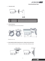
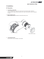
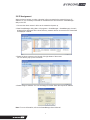
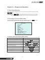
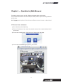
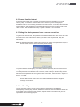
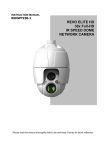
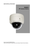
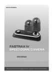
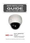
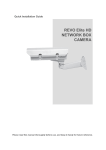
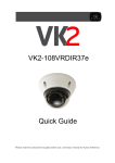
Quick Installation Guide IR Bullet Network Camera Please read this manual thoroughly before use, and keep it handy for future reference. Quick Installation Guide 1. Description The Network Camera supports the network service for a sensor image with progressive scan, which can be monitored on a real-time screen regardless of distances and locations. By using its dedicated program, many users are able to have an access to the Network Camera at once or a single user can monitor various network cameras at the same time. It also enables users to play, store and retrieve a monitoring image by using a PC. All the settings and real-time monitoring screens are also provided through an access to the web. The Network Camera is fully featured for security surveillance and remote monitoring needs. It is based on the DSP compression chip, and makes it available on the network as real-time, full frame rate Motion JPEG and H.264 (or MPEG-4) video streams. The alarm input and alarm output can be used to connect various third party devices, such as, door sensors and alarm bells. • Installation Steps Follow these steps to install the network camera on your local network (LAN): 1. 2. 3. 4. • Check the package contents against the list below. Connect the Network Camera Set an IP address. Set the password. Package Component The system comes with the following components: Camera Unit • Installation CD Installation Guide Accessory Kit Contents in the installation CD 1. 2. 3. 4. 5. The The The The The User’s Manual SmartManager User’s Manual NCTitanium User’s Manual SmartManager Installation software NCTitanium Installation software Note: Check your package to make sure that you received the complete system, including all components shown above. 2 Quick Installation Guide • Connection Cable NO 1 2 Name Power Cable Ethernet Cable Description Cable for Power source (DC 12V) Cable for Ethernet (POE) Camera Dimension See the diagrams below for the exact dimension Dimensions Unit: mm Base Installation(Cable through the wall or ceiling with the mount base) Secure the camera to the wall or ceiling by the camera stand (individual purchase). Ceiling Mount W all Mount 3 Quick Installation Guide 2. Installation 2.1 Connection • Connecting to the RJ-45 Connect a standard RJ-45 cable to the network port of the network camera. Generally a cross-over cable is used for directly connection to PC, while a direct cable is used for connection to a hub. Micro SD memory slot Remove the front cap of the camera to insert the SD memory card. SD memory card slot Remove the front cap • Connecting the Power Connect the DC 12V power adaptor to the camera. 4 Quick Installation Guide 2.2 Network Connection and IP assignment The Network Camera supports the operation through the network. When a camera is first connected to the network it has no IP address. So, it is necessary to allocate an IP address to the device with the “Smart Manager” utility on the CD. The factory default IP is “192.168.30.220”. 1. 2. Connect the Network Camera / device to the network and power up. Start SmartManager utility (Start>All programs>SmartManager>SmartManager), the main window will be displayed, after a short while any network devices connected to the network will be displayed in the list. 3. Select the camera on the list and click right button of the mouse. You can see the pop-up menu below. 4. Select Assign IP. You cam see a Assign IP window. Enter the required IP address. Note: For more information, refer to the Smart Manger User’s Manual. 5 2.3 Basic Configuration of Dome Camera System No. Wire Color Description 1 Red: 12VDC+ White: 12VDC- Main Power: 2pin terminal 2 Pink, Brown Heater Power(Option): 3pin terminal 3 Black: GND Gray: Alarm Input Yellow: GND Black&White: Alarm Output Green: RS485+ Blue: RS485- Alarm Input/Output, RS485: 6pin terminal 4 Black Ethernet: RJ45 Modular Jack 5 Yellow Video Composite Output: BNC Jack 6 Red Audio line output: RCA Jack 7 White Audio line input: RCA Jack The dome camera must be installed by qualified service personnel in accordance with all local and federal electrical and building codes. 6 2.4 Setting Dome Camera Address (ID) To prevent damage, each dome camera must have a unique address (ID). When installing multiple dome cameras using a multiplexer, it is suggested that the dome camera address match the multiplexer port number. The factory default setting is 1. 2.5 Connections • Connecting to the RJ-45 Connect a standard RJ-45 cable to the network port of the dome camera. Generally a crossover cable is used for directly connection to PC, while a direct cable is used for connection to a hub. • Connecting Alarms AI (Alarm Input) You can use external devices to signal the dome camera to react on events. Mechanical or electrical switches can be wired to the AI (Alarm Input) and G (Ground) connectors. G (Ground) NOTE: All the connectors marked G or GND are common. Connect the ground side of the alarm input and/or alarm output to the G (Ground) connector. AO (Alarm Output) The dome camera can activate external devices such as buzzers or lights. Connect the device to the AO (Alarm Output) and G (Ground) connectors. • Connecting to the RS485 The dome camera can be controlled remotely by an external device or control system, such as a control keyboard, using RS485 half-duplex serial communications signals. • Connecting Video out connector Connect the video out (BNC) connector to the monitor or video input. • Connecting the Power Connect the power of 12VDC 1.0A for the dome camera. When using a 12VDC adapter, connector the positive(+) pole to the ‘+’ position and the negative(-) pole to the ‘-‘ position. Use satisfy clause 2.5 of IEC60950-1/UL60950-1 or Certified/Listed Class 2 power source only. 7 2.6 IP Assignment When the dome camera, encoder or decoder is first connected to the network it has no IP address. So, it is necessary to allocate an IP address to the device with the “SmartManager” utility on the CD. 1. Connect the dome camera / device to the network and power up. 2. Start SmartManager utility (Start > All programs > SmartManager > SmartManager), the main window will be displayed, after a short while any network devices connected to the network will be displayed in the list. 3. Select the dome camera on the list and click right button of the mouse. You can see the pop-up menu as below. 4. Select Assign IP Address. You can see Assign IP window. Enter the required IP address. Note: For more information, refer to the SmartManager User’s Manual. 8 2.7 Getting Started Once installed apply power to the dome camera. The dome camera will start a configuration sequence. PRESET TITLE AREA TITLE FUNCTION UNDER RUNNING INFORMATION DISPLAY 001 AF AE STATUS of FOCUS and AE CAMERA TITLE EMPTY DATA CAMERA ID DOMEID:001 W→360.0 090.0 PAN & TILT ANGLE VIEW DIRECTION OSD Position The dome can move the OSD position in the OSD position setup. (AREA TITLE) (FUNC TITLE ) (AF AE) (CTRL KEY TO MOVE) SAVE AND EXIT(ESC TO CANCEL) (DOME ID…) (ANGLE…) OSD Position Setup 9 Chapter 3 — Program and Operation 3.1 Dome Camera Selection Before you program or operate a dome camera, you must select the dome camera by pressing No. + CAM keys. Example: Pressing 1 , 0 + CAM keys sequentially will select dome camera 10. The selected dome camera ID will be displayed on the LCD monitor of the keyboard controller. 3.2 Accessing the On-Screen Menu Utility You can call up the On-screen menu utility on your monitor by pressing the MENU key on the keyboard controller, the following On-screen menu utility will appear: DOME MENU AUTO SCAN PRESET TOUR PATTERN AREA TITLE PRIVACY ZONE CAMERA DOME SETUP DOME COMMUNICATION FUNCTION RUN EXIT(ESC TO EXIT) 3.3 How to control the On-Screen Menu Utility Function Button Call the On-screen menu utility. MENU Navigate through the menu items. Joystick up or down Go into the sub-menu items. Joystick left or right or IRIS Open Change value. Enter the editing title mode. Joystick left or right or Zoom handle twist or Tele , Wide Change value of angle. CTRL + Joystick Enter the changing angle mode. IRIS Open Exit the changing angle mode. IRIS Close Escape (EXIT) ESC 10 Chapter 4 — Operation by Web Browser The network camera can be used with Windows operating system and browsers. The recommended browsers are Internet Explorer, Safari, Firefox, Opera and Google Chrome with Windows. Note: To view streaming video in Microsoft Internet Explorer, set your browser to allow ActiveX controls. 4.1 Access from a browser 1) Start a browser (Internet Explorer). 2) Enter the IP address or host name of the network camera in the Location/Address field of your browser. 3) You can see a starting page. Click Live View or Setup to enter web page. 4) The encoder’s Live View page appears in your browser. 11 4.2 Access from the internet Access from the internet once connected, the network camera is accessible on your local network (LAN). To access the video encoder from the Internet you must configure your broadband router to allow incoming data traffic to the video encoder. To do this, enable the NAT traversal feature, which will attempt to automatically configure the router to allow access to the video encoder. This is enabled from Setup > System > Network > NAT Traversal. 4.3 Setting the admin password over a secure connection To gain access to the product, the password for the default administrator user must be set. This is done in the “Admin Password” dialog, which is displayed when the network camera is accessed for the setup at the first time. Enter your admin name and password, set by the administrator. Note: The default administrator username and password is “admin”. If the password is lost, the network camera must be reset to the factory default settings. To prevent network eavesdropping when setting the admin password, this can be done via an encrypted HTTPS connection, which requires an HTTPS certificate (see note below). To set the password via a standard HTTP connection, enter it directly in the first dialog shown below. To set the password via an encrypted HTTPS connection, please see Setup > System > Security > HTTPS. Note: HTTPS (Hypertext Transfer Protocol over SSL) is a protocol used to encrypt the traffic between web browsers and servers. The HTTPS certificate controls the encrypted exchange of information. 4.4 Live View Page The live view page comes in seven screen modes like 704x576(480), 704x288(240), 352x288(240), 176x144(120), 640x480, 320x240 and 160x120. Users are allowed to select the most suitable one out of those modes. Please, adjust the mode in accordance with your PC specifications and monitoring purposes. 12 1) General controls The video drop-down list allows you to select a customized or preprogrammed video stream on the live view page. Stream profiles are configured under Setup > Basic Configuration > Video & Image. The resolution drop-down list allows you to select the most suitable one out of video resolutions to be displayed on live view page. The protocol drop-down list allows you to select which combination of protocols and methods to use depends on your viewing requirements, and on the properties of your network. The preset drop-down list allows you to select the preset number for the PTZ camera being used. This icon is inactivated if the PTZ settings are not set. 2) Control toolbar The live viewer toolbar is available in the web browser page only. It displays the following buttons: The Stop button stops the video stream being played. Pressing the key again toggles the start and stop. The Start button connects to the network camera or start playing a video stream. The Pause button pause the video stream being played. The Snapshot button takes a snapshot of the current image. The location where the image is saved can be specified. The digital zoom activates a zoom-in or zoom-out function for video image on the live screen. The Full Screen button causes the video image to fill the entire screen area. No other windows will be visible. Press the 'Esc' button on the computer keyboard to cancel full screen view. The Manual Trigger button activates a pop-up window to manually start or stop the event. The Camera Menu button activates a pop-up window for camera menu control. The PTZ button activates a pop-up window for Pan, Tilt and Zoom control. 13 Use this scale to control the volume of the speakers. Use this scale to control the volume of the microphone. Use this scale to control the volume of the speakers and microphones. 3) Camera Menu controls If the network camera has been appropriately configured, the Live View page displays the controls available for the OSD menu. 4) Pan/Tilt/Zoom controls If the network camera has been appropriately configured, the Live View page displays the controls available for the PTZ (Pan Tilt Zoom) or PT device installed. The administrator can enable/disable the controls for specified users. 5) Video and Audio Streams The network camera provides several images and video stream formats. Your requirements and the properties of your network will determine the type you use. The Live View page in the network camera provides access to H.264, MPEG-4 and Motion JPEG video streams, and to the list of available video streams. Other applications and clients can also access these video streams/images directly, without going via the Live View page. 4.5 Network Camera Setup This section describes how to configure the network camera, and is intended for product Administrators, who have unrestricted access to all the Setup tools; and Operators, who have access to the settings for Basic, Live View, Video & Image, Audio, Event, and System Configuration. You can configure the network camera by clicking Setup in the top right-hand corner of the Live View page. Click on this page to access the online help that explains the setup tools. When accessing the network camera for the first time, the “Admin Password” dialog appears. Enter your admin name and password, set by the administrator. Note: If the password is lost, the network camera must be reset to the factory default settings. 14 4.6 Resetting to the factory default settings To reset the network camera to the original factory settings, go to the Setup > System > Maintenance web page or use the control button on the network camera, as described below: • Using the Reset Button Follow the instructions below to reset the network camera to the factory default settings using the Reset Button. 1. Switch off the network camera by disconnecting the power adapter. 2. Open the lens cover. 3. Press and hold the Control Button (SW1) on the board with your finger while reconnecting the power. 4. Keep the Control button (SW1) pressed during about 2 seconds. 5. Release the Control Button (SW1). 6. The network camera resets to factory defaults and restarts after completing the factory reset. 7. Close the lens cover. CAUTION: When performing a Factory Reset, you will lose any settings you have saved. 4.7 System Requirement for Web Browser Operating System: Microsoft Windows 98, Microsoft Windows ME, Microsoft Windows 2000, Microsoft Windows XP, or Microsoft Windows Vista CPU: Over Pentium IV 2.4Ghz, 512MB RAM, 10GB free disk or higher VGA: AGP, Video RAM 32MB or higher (1024x768, 24bpp or higher) 4.8 More Information For more information, please see the Network Camera User’s Manual, which is available on the CD included in this package. 15 22X PTZ III NETWORK DOME CAMERA Printed in Korea 50302800B