1
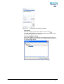
Application Bucket Dredging PDS2000 Version 1.0.2 June 2010 RESON B.V. Stuttgartstraat 42- 44 3047 AS Rotterdam The Netherlands Tel.: +31 (0)10 245 15 00 www.reson.nl Amendment Record Sheet Rev. Date Reason for Modifications 1.0.2 10/06/2010 New RESON logo added. 1.0.1 15/03/2010 Small modification 1.0.0 04/03/2010 First version of the Bucket Dredging Manual. Contents 1 Introduction 1 1.1 Bucket Dredging ..................................................................................................... 1 2 Quick Setup Project 3 2.1 Introduction............................................................................................................. 3 2.2 Vessel Configuration .............................................................................................. 3 2.2.1 Geometry ...................................................................................................... 3 2.2.2 Equipment ..................................................................................................... 5 2.2.2.1 Dredge Positioning System (Bucket)................................................... 6 2.2.2.2 Positioning System Geogs .................................................................. 8 2.2.2.3 Compass ............................................................................................. 8 2.2.2.4 VRU ..................................................................................................... 8 2.2.2.5 Depth Sensor....................................................................................... 8 2.2.2.6 Tide Gauge.......................................................................................... 9 2.2.3 Computations................................................................................................ 9 2.2.4 Data Source .................................................................................................. 9 2.2.5 Guidance..................................................................................................... 10 2.2.6 Logging ....................................................................................................... 10 2.3 Acquisition ............................................................................................................ 11 2.3.1 Plan View – General Dredge Operation ..................................................... 12 2.3.1.1 Plan View Properties ......................................................................... 13 2.3.1.2 Coverage Settings ............................................................................. 14 2.3.2 Profile – Realtime Design View .................................................................. 15 2.3.2.1 Profile Properties ............................................................................... 17 3 Calibration 19 3.1 Introduction........................................................................................................... 19 3.2 Calibration Inclinometer........................................................................................ 19 4 Vessel Configuration 21 4.1 Introduction........................................................................................................... 21 4.2 Vessel Configuration ............................................................................................ 22 4.2.1 Geometry Page........................................................................................... 22 4.2.1.1 Vessel Contour .................................................................................. 22 4.2.1.2 Offsets ............................................................................................... 25 4.2.2 Equipment Page ......................................................................................... 25 PDS2000 - Application Bucket Dredging Contents • i 4.2.2.1 Dredge Positioning System (Bucket) ................................................ 26 4.2.2.2 Positioning System Geogs................................................................ 30 4.2.2.3 Compass ........................................................................................... 32 4.2.2.4 VRU................................................................................................... 33 4.2.2.5 Depth Sensor .................................................................................... 33 4.2.2.6 Tide Gauge ....................................................................................... 35 4.2.3 Computations Page .................................................................................... 35 4.2.4 Data Source Page ...................................................................................... 37 4.2.5 Guidance Page........................................................................................... 38 4.2.6 Logging Page ............................................................................................. 38 5 Acquisition 41 5.1 Introduction .......................................................................................................... 41 5.2 Plan View – General Dredge Operation............................................................... 43 5.2.1 Plan View Toolbar and Context Menu........................................................ 43 5.2.2 Plan View Properties .................................................................................. 46 5.2.3 Plan View Layer Control ............................................................................. 48 5.2.4 Coverage Settings ...................................................................................... 49 5.3 Profile – Realtime Design View............................................................................ 50 5.3.1 Profile Toolbar and Context Menu.............................................................. 51 5.3.2 Profile Properties ........................................................................................ 52 5.3.3 Profile Layer Control................................................................................... 54 ii • Contents PDS2000 - Application Bucket Dredging Figures Figure 2-1 Example of a right view of a bucket chain........................................................................... 4 Figure 2-2 Example of a top view of a bucket chain............................................................................. 4 Figure 2-3 Drawing of the bucket chain with the origin (0,0,0) ............................................................. 5 Figure 2-4 Equipment page .................................................................................................................. 6 Figure 2-5 First properties window of the Dredge Positioning System (Bucket) .................................. 6 Figure 2-6 Drawing of the bucket chain ................................................................................................ 7 Figure 2-7 Data Source page with the depth sensor as primary data group........................................ 9 Figure 2-8 Design Model tab in the Guidance page ........................................................................... 10 Figure 2-9 Logging page with PDS2000 Grid Model .......................................................................... 10 Figure 2-10 Example of a layout in the Acquisition............................................................................... 11 Figure 2-11 Plan View – General Dredge Operation view with orientation mode ‘Heading Up’ .......... 12 Figure 2-12 The Properties of the Plan View – General Dredge Operation view................................. 13 Figure 2-13 Coverage Settings for the plan view.................................................................................. 14 Figure 2-14 Profile – Realtime Design view with a right view of the bucket chain, grid model and design model ..................................................................................................................... 15 Figure 2-15 Select Source Item for the Up-Down Indicator.................................................................. 16 Figure 2-16 Properties of the Profile – Realtime Design view .............................................................. 17 Figure 3-1 Bucket chain for the calibration of the inclinometer........................................................... 19 Figure 4-1 Configuration window ........................................................................................................ 21 Figure 4-2 Geometry page of the vessel configuration....................................................................... 22 Figure 4-3 Example of a top view of a vessel ..................................................................................... 23 Figure 4-4 Example of a right view of a bucket chain......................................................................... 23 Figure 4-5 Drawing of the bucket chain with the origin (0,0,0) ........................................................... 24 Figure 4-6 Equipment page ................................................................................................................ 25 Figure 4-7 First properties window of the Dredge Positioning System (Bucket) ................................ 26 Figure 4-8 Drawing of the bucket chain .............................................................................................. 27 Figure 4-9 Second properties window of the Dredge Positioning System (Bucket) ........................... 28 Figure 4-10 Third properties window of the Dredge Positioning System (Bucket) ............................... 29 Figure 4-11 First properties window of the Positioning System Geogs ................................................ 30 Figure 4-12 Third properties window of the Positioning System Geogs............................................... 31 Figure 4-13 First properties window of the Compass ........................................................................... 32 Figure 4-14 First properties window of the VRU................................................................................... 33 Figure 4-15 First properties window of the Depth sensor..................................................................... 34 Figure 4-16 Second properties window of the Depth sensor................................................................ 34 Figure 4-17 Properties window of the Tide gauge ................................................................................ 35 Figure 4-18 Advanced Computations with a tide computation ............................................................. 36 Figure 4-19 Properties window of the Tide computation ...................................................................... 36 PDS2000 - Application Bucket Dredging Figures • iii Figure 4-20 Data Source page with the depth sensor as primary data group ..................................... 37 Figure 4-21 Design Model tab in the Guidance page........................................................................... 38 Figure 4-22 Logging page with PDS2000 Grid Model.......................................................................... 39 Figure 4-23 Select the device data for the grid model logging............................................................. 39 Figure 5-1 Example of a layout in the Acquisition .............................................................................. 42 Figure 5-2 Plan View – General Dredge Operation view with orientation mode ‘Heading Up’ .......... 43 Figure 5-3 Measure window in the plan views ................................................................................... 44 Figure 5-4 Measure Relative window ................................................................................................. 44 Figure 5-5 Find C-Map object in the plan view................................................................................... 45 Figure 5-6 The Properties of the Plan View – General Dredge Operation view ................................ 46 Figure 5-7 Layer Control of the Plan View – General Dredge Operation........................................... 48 Figure 5-8 Coverage Settings ............................................................................................................ 49 Figure 5-9 Profile – Realtime Design view with a right view of the bucket chain, grid model and design model..................................................................................................................... 50 Figure 5-10 Select Source Item for the Up-Down Indicator ................................................................. 51 Figure 5-11 Properties of the Profile – Realtime Design view.............................................................. 52 Figure 5-12 Layer Control of the Profile – Realtime Design view ........................................................ 54 iv • Figures PDS2000 - Application Bucket Dredging 1 Introduction 1.1 Bucket Dredging The application type ‘Bucket Dredging’ is for a project where for dredging a bucket dredger is used. In the first chapter of this application manual a brief explanation of the setup of a bucket dredging project will be discussed. At the end of this chapter some extra information about the views in the Acquisition will be given. This chapter can be used by experienced PDS2000 users. The next chapter will discuss the calibration of the inclinometer on the bucket chain. The last two chapters will explain in more detail the setup of the project and the Acquisition. This manual has to be used in conjunction with the PDS2000 User Manual. This manual is also available as a HTML Help file. Press F1 or select Help > Help Topics to open the PDS2000 help files. PDS2000 - Application Bucket Dredging Introduction • 1 2 Quick Setup Project 2.1 Introduction PDS2000 needs a project, an application type and a configuration before any of the modules can be started. In the chapter ‘Starting PDS2000’ of the PDS2000 User Manual is described how to setup a project with an application type and a configuration. For the new project the application type should be ‘Bucket Dredging’. ( In this chapter the Vessel Configuration and the Acquisition will be explained in a way that an experienced PDS2000 user can setup and run a bucket dredging project. For a detailed explanation of the setup see the chapters ‘Vessel Configuration’ (on page 21) and ‘Acquisition’ (on page 41). 2.2 Vessel Configuration The general information about the Vessel Configuration is explained in the chapter ‘Vessel Configuration’ of the PDS2000 User Manual. 2.2.1 Geometry In the Geometry page the contours of the vessel and the bucket chain has to be drawn. For the contours a top view and at least one side view have to be drawn. The side views of all the contours should be from the same side, so the vessel with the bucket chain can be displayed in a Profile – Realtime Design view in the Acquisition (see page 15). PDS2000 - Application Bucket Dredging Quick Setup Project • 3 4 • Quick Setup Project Figure 2-1 Example of a right view of a bucket chain Figure 2-2 Example of a top view of a bucket chain PDS2000 - Application Bucket Dredging The origin (0,0,0) of the drawing for a bucket chain should be in the centre of the bottom bucket chain wheel. The negative Y-axis has to go through the bucket chain point (see below). Bucket Chain Point +Z (0,0,0) +Y Figure 2-3 Drawing of the bucket chain with the origin (0,0,0) The offsets, which are needed for the bucket dredging, have to be added to the offset table in the Geometry page. The possible vessel offsets are: Antenna of a Positioning System Geogs Bucket Chain Point Top Bucket Chain Wheel VRU Depth Sensor The Zero offset is the zero point of the vessel. See page 7 for a drawing of the bucket chain with the bucket chain point and the top bucket chain wheel. 2.2.2 Equipment In the Equipment page the sensors used for the bucket dredging are: Dredge Positioning System (Bucket) Positioning System Geogs Compass VRU If no RTK system is used as positioning system then the following equipment is needed: Depth Sensor Tide gauge(s) PDS2000 - Application Bucket Dredging Quick Setup Project • 5 Figure 2-4 ( Equipment page For most of the items in the properties the default settings can be used. Below only the essential settings in the properties of the sensors will be discussed. 2.2.2.1 Dredge Positioning System (Bucket) This device driver calculates the position and the depth of the lowest point of the bucket chain with the data from the inclinometer on the ladder. The first properties window (‘ Figure 2-5 (Bucket) 6 • Quick Setup Project Dredge Positioning System (Bucket)’): First properties window of the Dredge Positioning System PDS2000 - Application Bucket Dredging Bucket Chain Wheel Radius Top Bucket Chain Wheel Bucket Chain Point Bottom Bucket Chain Wheel La dd e rL en gth Bucket Dredge Radius Figure 2-6 Drawing of the bucket chain Device Offset The offset of the bucket chain point as defined in the Geometry page. Length Segment 1 The ladder length in meters. Sensor 1 Multiplication Factor The multiplication factor for the inclinometer reading. Sensor 1 Offset The offset for the inclinometer reading. The offset can be calculated with the calibration of the inclinometer (see page 19). Top Bucket Wheel Offset The offset of the top bucket chain wheel as defined in the Geometry page. Bucket Chain Length The total bucket chain length. The length can be obtained by measure the length over 5 buckets with a tape measure and divide the observation by 5, then multiply this by the number of buckets on the chain. Bucket Chain Depth Correction The dredge depth can be corrected with this correction; a positive correction will make the dredge depth deeper. Bucket Chain Wheel Radius The radius of the top or bottom bucket chain wheel. Bucket Dredge Radius The distance from the centre of the bottom bucket chain wheel to the edge of the bucket when it passed the bottom bucket chain wheel. Effective Width The width of the bucket. Dredge Head Shape Select the contour file for the bucket chain that is made in the Geometry page. PDS2000 - Application Bucket Dredging Quick Setup Project • 7 In the second and third properties window (‘ Drag-head Relative Position’ and ‘ Drag-head Absolute Position’) the defaults settings can be used. ( In the third properties window the option ‘Grid Model Update Mode’ is set on Set Z Value to give the best update of the active grid model. 2.2.2.2 Positioning System Geogs ( If this system is not a RTK system then a depth sensor and one or more tide gauges have to be interfaced (see page 8). In the first properties window (‘ Positioning System Geogs): Device Offset The offset of the GPS antenna as defined in the Geometry page. In the third properties window (‘ Reference Point Computation’): Height Source Select for the computation of the height related to the received position the Z of the GPS RTK system or the tidal information from tide gauges or predicted tides. 2.2.2.3 Compass The compass is used to get a heading of the vessel. In the first properties window (‘ Compass’): Heading Correction The correction as derived from the compass calibration. 2.2.2.4 VRU A VRU is used to measure the attitude (roll, pitch) and heave) of the vessel. The first properties window (‘ VRU’): Device Offset The offset of the motion sensor as defined in the Geometry page. Heading Correction If the VRU is not aligned with the vessel, enter the misalignment of the VRU. Roll / Pitch Correction A roll and pitch correction, derived from the VRU calibration, can be entered in the properties. Check the sign convention of the roll and pitch before entering the values. 2.2.2.5 Depth Sensor When the positioning system is not a RTK system a depth sensor is used to measure the draught of the vessel. The first properties window (‘ Depth sensor’): Device Offset The offset of the depth sensor as defined in the Geometry. When a depth sensor is used the sensor has to be set as primary data group for the sea level data source in the Data Source (see page 9) 8 • Quick Setup Project PDS2000 - Application Bucket Dredging 2.2.2.6 Tide Gauge When the positioning system is not a RTK system one or more tide gauges are used to measure tide information to calculate the absolute depth. The properties window (‘ Tide gauge’): Tide Stations Select one or more tide stations that will be used to calculate the tide correction. 2.2.3 Computations A ‘ Tide Computation’ has to be created in the Advanced Computations to open the advanced computations). The tide (click on computation is needed to compute the tidal correction. Tide Reduction Computation Mode When one tide station is used, select the mode Single Tide Station. When more tide stations are used, select the mode Multiple Tide Stations or when the tide stations are along a route the mode Tide Stations Along Route. Tide Stations Select the tide station(s) that will be used for the tide computation. 2.2.4 Data Source In the Data Source page the sea level data source will have two data groups when a depth sensor is used. Figure 2-7 Data Source page with the depth sensor as primary data group By default the data group ‘Sealevel (Reference point)’ will be the primary data group. To use the depth sensor for calculating the sea level the depth sensor has to be the primary data source. Select the depth sensor and click on top. PDS2000 - Application Bucket Dredging to move the depth sensor to the Quick Setup Project • 9 2.2.5 Guidance Select a design model that will be used as reference for the bucket dredging. This can be a 3D design model or a grid model. Figure 2-8 Design Model tab in the Guidance page The underdredge and overdredge limits are displayed as extra lines in the Profile – Realtime Design view (see page 15). 2.2.6 Logging A grid model of the dredge location with the actual depths should be created. Select in the logging page this grid model, so that during the bucket dredging the grid model can be updated with actual dredge depths. Figure 2-9 10 • Quick Setup Project Logging page with PDS2000 Grid Model PDS2000 - Application Bucket Dredging 2.3 Acquisition In the Acquisition several views can be created to display the relevant information for the bucket dredger. The minimum should be a Plan View where the bucket dredger with the bucket chain is visible and one or more Profile views for a side or back view of the bucket dredger with the bucket chain. See for other views, which can be used in the Acquisition, the chapter ‘Views’ in the PDS2000 User Manual. Figure 2-10 PDS2000 - Application Bucket Dredging Example of a layout in the Acquisition Quick Setup Project • 11 2.3.1 Plan View – General Dredge Operation This plan view will show the bucket dredger with the bucket chain in a top view with additional information. Figure 2-11 Plan View – General Dredge Operation view with orientation mode ‘Heading Up’ When no color table can be selected, then a color table has to be created in the Explorer before it can be selected (see for information the PDS2000 User Manual). ( 12 • Quick Setup Project When this plan view is created, automatically the grid model and the dredge layer with the bucket dredger information are loaded. Only the active grid model will be shown in black, because there is no color table selected for the grid model. Click on in the toolbar or select ‘Coverage Setting’ in the context menu of the plan view to open the Coverage Settings and select the right color table for the Z Average of the grid model (see page 14). Set the view in the Follow Vessel mode when the vessel is not displayed in the plan view. Click on in the toolbar to set the Follow Vessel mode on. PDS2000 - Application Bucket Dredging 2.3.1.1 Plan View Properties Click on in the toolbar or select ‘Properties’ in the context menu to open the Properties of the plan view. Figure 2-12 The Properties of the Plan View – General Dredge Operation view By default the item ‘Position Source’ is set on the Tracking Point. If the bottom of the bucket chain has to be followed, select for the ‘Position Source’ the Drag-head Absolute Position. For the item ‘Attach To’ can then the Dredge Point be selected. PDS2000 - Application Bucket Dredging Quick Setup Project • 13 2.3.1.2 Coverage Settings Click on in the plan view toolbar or select ‘Coverage Settings’ in the context menu of the plan view to open the Coverage Settings. Figure 2-13 Coverage Settings for the plan view If a grid model has to be shown in the plan view, check the option ‘Grid model’ on top of the window. Check then under ‘Grid Model’ the data type that has to be shown in the plan view. Select the right color table for that data type. If a grid model difference has to be shown in the plan view, check the option ‘Difference’ and select the right color table. With the Coverage Settings it is easy to switch between the active grid model and the active grid model difference in the plan view. Check one of the two options and the settings in the Layers are automatically updated. Check the option Show color table if the user wants to show the color table of the selected option on the right hand side of the plan view. 14 • Quick Setup Project PDS2000 - Application Bucket Dredging 2.3.2 Profile – Realtime Design View The Profile – Realtime Design view will show the bucket dredger with the bucket chain as a side view with additional information. Figure 2-14 Profile – Realtime Design view with a right view of the bucket chain, grid model and design model The underdredge and overdredge limits have to be specified in the Design Model tab in the Guidance page (see page 10). The active design model and active grid model are automatically displayed in the view. The DTM update shape is automatically calculated with the settings as specified in the properties of the Dredge Positioning System (see page 6). The shape displays the dredge area of the bucket chain. With the use of this shape the update for the active grid model is calculated. For the Up-Down Indicator every item that is available or calculated in PDS2000 can be selected. Here above is for instance the computation ‘ Design Difference’ (in the ‘ Drag-head Absolute Position’) displayed. Click with the right mouse button in the Up-Down Indicator area to open the Layer Control of the area. Select in the Up-Down Indicator Layer the item ‘Source Item’ and select at the bottom the item that has to be displayed (see below). The computation ‘ Design Difference’ shows the difference between the lowest point of the bucket chain and Z-value of the design model. Another option is to select the computation ‘ Absolute Z Dredge Head(1)’, which shows the absolute depth of the lowest point of the bucket chain. PDS2000 - Application Bucket Dredging Quick Setup Project • 15 Figure 2-15 16 • Quick Setup Project Select Source Item for the Up-Down Indicator PDS2000 - Application Bucket Dredging 2.3.2.1 Profile Properties Click on in the toolbar or select ‘Properties’ in the context menu to open the Properties of the profile view. Figure 2-16 ( ( Properties of the Profile – Realtime Design view By default the item ‘Position Source’ is set on the Drag-head Absolute Position and the item ‘Attach To’ is set on Dredge Point. Do not change the setting for the ‘Position Source’. For ‘Attach To’ the user can choose between Dredge Point or Sensor Reference Point, where with Dredge Point the bottom of the bucket chain is followed and with Sensor Reference Point the bucket chain point is followed. When the Profile – Realtime Design view is created the view is always from the Left. With the item ‘Profile View Side’ the view side can be changed to Right, Front or Back. The left Profile – Realtime Design view in the figure on page 11 is a view from the back. The different view sides have to be made as contours in the Geometry page (see page 3). PDS2000 - Application Bucket Dredging Quick Setup Project • 17 3 Calibration 3.1 Introduction At the moment there is no procedure in the PDS2000 software to calibrate the angle of the bucket chain. Below a method is explained how to calibrate the angle of the bucket chain and where to enter the computed value in the properties of the device driver. 3.2 Calibration Inclinometer The inclinometer will be mounted on the ladder of the bucket chain. To be sure that the reading from the inclinometer matches with the angle of the ladder an inclinometer calibration has to be done. For the best calibration the total length of the ladder has to be used. Move the bucket chain so that the centre of the bottom bucket chain wheel is on the waterline (see below), then measure from the bucket chain point to the waterline. Bucket Chain Point La dd Height Above Waterline Bottom Bucket Chain Wheel er Le n gth Waterline Figure 3-1 Bucket chain for the calibration of the inclinometer When it is difficult to measure to the waterline, measure to the deck and then from the deck to the waterline on starboard and port. Take the mean PDS2000 - Application Bucket Dredging Calibration • 19 from both sides plus the height to the deck as the height above the waterline. From the ladder length and the height of the bucket chain point above the waterline an angle can be calculated. When it is difficult to put the centre of the bottom bucket chain wheel on the waterline, it is also possible to put an other point of the ladder on the waterline. Then also the distance from that point to the bucket chain point has to be measured. The difference between the calculated angle and the inclinometer reading can be entered as the ‘Sensor 1 Offset’ in the properties of the Dredge Positioning System (Bucket) (see page 7). Check the sign convention before entering the correction. 20 • Calibration PDS2000 - Application Bucket Dredging 4 Vessel Configuration 4.1 Introduction In the chapter ‘Starting PDS2000’ of the PDS2000 User Manual is described how to setup a project with an application type and a configuration. When a project is created with the application type ‘Bucket Dredging’ the from the toolbar configuration can be started in the Control Center with or with the menu option Acquisition > Configuration. Figure 4-1 Configuration window In the Configuration a vessel has to be added to the configuration. Use (under Local) to add an existing vessel or create a new one. (under When a vessel is added, select the vessel and click on Local) to open the Vessel Configuration. PDS2000 - Application Bucket Dredging Vessel Configuration • 21 4.2 Vessel Configuration The Vessel Configuration window has several tab pages where the complete setup for the bucket dredger can be defined. 4.2.1 Geometry Page Figure 4-2 Geometry page of the vessel configuration In the Geometry page the contours for the vessel and the bucket chain has to be created and all the offsets on the vessel has to be defined. Only the relevant items will be discussed below, for the other items the default settings can be used. ( Vessel contour Click on to create a new vessel contour or click on to open the selected vessel contour. In both cases the vessel contour editor will be opened (see below). When the user is finished with the contours, select the vessel contour as the active contour, so that it will be displayed in the Acquisition. ( Vessel wireframe A vessel wireframe is a 3D drawing of the vessel and can be used in the 3D views in PDS2000. It is also possible to display the wireframe in the standard 2D views. These wireframes should be 3D DXF files. Select the wireframe of the vessel so that will be displayed in the Acquisition. This is just a list of offsets, in the Equipment page the offsets are assigned to the sensors. Offsets An offset is a point of interest on the vessel, such as the location of a sensor (see page 25). The ’Zero Offset’ is a PDS2000 pre-defined offset, the CRP and cannot be changed. Click on for an overview of the vessel contour and offsets. A topand a starboard view of the vessel are shown. If no vessel contour is available, a default contour will be used in the views. 4.2.1.1 Vessel Contour For the contours a top view and at least one side view have to be drawn. The side views of all the contours should be from the same side, so the vessel with the bucket chain can be displayed in a Profile – Realtime Design view in the Acquisition (see page 50). 22 • Vessel Configuration PDS2000 - Application Bucket Dredging ( One contour file can contain contours from different view sides, for instance a top and a right side view. Figure 4-3 Example of a top view of a vessel Figure 4-4 Example of a right view of a bucket chain PDS2000 - Application Bucket Dredging Vessel Configuration • 23 The origin (0,0,0) of the drawing for a bucket chain should be in the centre of the bottom bucket chain wheel. The negative Y-axis has to go through the bucket chain point (see below). Bucket Chain Point +Z (0,0,0) +Y Figure 4-5 ( Drawing of the bucket chain with the origin (0,0,0) Due to the complicity of the drawing as displayed above it is advisable to use the DXF import option to create the vessel and bucket chain contours. First select the view side that matches with the view side in the DXF file. Select from the menu bar of the Vessel Contour editor the option Import > From DXF… to import a contour. The origin and coordinates used in the DXF file should match with the coordinates and the origin of the vessel or the bucket chain. If the user has no DXF data available, the edit tools in the vessel contour editor have to be used. The relevant options in the right top panel of the vessel contour editor are: Name: Point(n) Add the X and Y value for point(n) in the vessel coordinate system. Type Point. If the point(n) is not a Start of Line or a Start of Polygon. Start of Line. If point(n) is the first point of a line. Until a new Start of Line or Start of Polygon is selected all points after this point will be part of the line. Start of Polygon. If point(n) is the first point of the polygon. Until a new Start of Line or Start of Polygon is selected all points after this point will be part of the polygon. The polygon will be solid. The buttons and options on the right side in the editor are: Add a new point to the contour. The added point comes always at the end of the list. Insert a new point above the location of the cursor in the list. Delete the selected point from the list. Select the view side of the vessel contour; top, bottom, left, right, front and back. 24 • Vessel Configuration PDS2000 - Application Bucket Dredging , Zoom Extents, Zoom In / Out. Click on editor. to save the contour and to close the vessel contour 4.2.1.2 Offsets The offsets, that are needed for the bucket dredging, have to be added to the offset table in the Geometry page. The possible vessel offsets are offsets for: Antenna of a Positioning System Geogs Bucket Chain Point Top Bucket Chain Wheel VRU Depth Sensor The Zero offset is the zero point of the vessel. See Dredge Positioning System (Bucket) on page 26 for a drawing of the bucket chain with the bucket chain point and the top bucket chain wheel. 4.2.2 Equipment Page In the Equipment page the sensors used for the bucket dredging are: Dredge Positioning System (Bucket) (see below) Positioning System Geogs (see page 30) Compass (see page 32) VRU (see page 33) If no RTK system is used as positioning system then the following equipment is needed: Depth Sensor (see page 33) Tide gauge(s) (see page 35) Figure 4-6 PDS2000 - Application Bucket Dredging Equipment page Vessel Configuration • 25 Select first one of the available Groups and then select in that group one of the available device drivers. Click on to add the selected driver to the list of devices on the right side. ( In the explanations of the different drivers only the items from the properties that are relevant for the bucket dredging application and can be set by the user will be discussed!!! 4.2.2.1 Dredge Positioning System (Bucket) This device driver calculates the position and the depth of the lowest point of the bucket chain with the data from the inclinometer on the ladder. The first properties window (‘ Figure 4-7 (Bucket) 26 • Vessel Configuration Dredge Positioning System (Bucket)’): First properties window of the Dredge Positioning System PDS2000 - Application Bucket Dredging Bucket Chain Wheel Radius Top Bucket Chain Wheel Bucket Chain Point Bottom Bucket Chain Wheel La dd e rL en gth Bucket Dredge Radius Figure 4-8 Drawing of the bucket chain Device Offset The offset of the bucket chain point as defined in the Geometry page. This offset is in vessel coordinates, not in bucket chain coordinates. Length Segment 1 The ladder length in meters; this is the length between the bucket chain point and the centre of the bottom bucket chain wheel (see figure above). Sensor 1 Multiplication Factor The multiplication factor for the inclinometer reading. Keep this value on 1 and change it only when it is really necessary. Sensor 1 Offset The offset for the inclinometer reading. Use this when there is a mismatch between the angle from the inclinometer and actual angle of the ladder as measured in the inclinometer calibration (see page 19). Top Bucket Wheel Offset The offset of the top bucket chain wheel as defined in the Geometry page. This offset is in vessel coordinates, not in bucket chain coordinates. Bucket Chain Length The total bucket chain length. The length can be obtained by measure the length over 5 buckets with a tape measure and divide the observation by 5, then multiply this by the number of buckets on the chain. Bucket Chain Depth Correction The dredge depth can be corrected with this correction; a positive correction will make the dredge depth deeper. Bucket Chain Wheel Radius The radius of the top or bottom bucket chain wheel. Bucket Dredge Radius The distance from the centre of the bottom bucket chain wheel to PDS2000 - Application Bucket Dredging Vessel Configuration • 27 the edge of the bucket when it passed the bottom bucket chain wheel. Effective Width The width of the bucket. Dredge Head Shape Select the contour file for the bucket chain that is made in the Geometry page. ( Wireframe If a wireframe (3D DXF file) is available for the bucket chain; select the DXF file for the bucket chain. In stead of the Dredge Head Shape as specified above this wireframe will then be used in the views of the Acquisition. The second properties window (‘ Figure 4-9 (Bucket) Drag-head Relative Position’): Second properties window of the Dredge Positioning System Apply VRU Data Disabled. No Roll and Pitch applied to compute the location of the lowest point of the bucket chain. (This is the default setting). Enabled. Roll and Pitch applied to the computation. Maximum Age VRU Data When the age of the latest VRU data is smaller than the number of milliseconds specified the VRU data will be applied to the dredge position. Only valid when the option ‘Apply VRU Data’ is Enabled. 28 • Vessel Configuration PDS2000 - Application Bucket Dredging The third properties window (‘ Figure 4-10 (Bucket) Drag-head Absolute Position’): Third properties window of the Dredge Positioning System Grid Model Update Mode Select the update mode for the active grid model that is specified in the logging (see page 38). The default setting Set Z Value is the best update mode for the grid model. With the right update mode the grid model that is displayed in the Plan View – General Dredge Operation (see page 43) and in the Profile – Realtime Design view (see page 50) will be updated. Other settings are Increment Hit Count, Add Registration Value, Set Registration Value, Volume Update and Fixed Volume Grab. Registration Value The value that will be used when the option ‘Grid Model Update Mode’ is set on Add Registration Value or Set Registration Value. Grid Model Logging Condition The logging condition for the grid model. The default setting Always is the best setting for the logging condition. Other settings are Status Signal, Status Dredging and Clam Shell Closing. Fill Empty Grid Model Cells Enabled. The empty cells in the grid model will be filled with the depth of the bottom of the bucket chain. (This is the default setting). Disabled. No empty cells will be filled. PDS2000 - Application Bucket Dredging Vessel Configuration • 29 4.2.2.2 Positioning System Geogs ( This sensor gives a position derived from several GPS satellites. If this system is not a RTK system then a depth sensor (see page 33) and one or more tide gauges (see page 35) have to be interfaced. The first properties window (‘ Figure 4-11 Positioning System Geogs’): First properties window of the Positioning System Geogs Device Offset The offset of the GPS antenna as defined in the Geometry page. Timestamp Mode In PDS2000 a time has to be attached to the received position. Computer Clock. The time of the computer. External Clock. The time from an external clock that has to be added to the equipment list. Time in Message. The time as is received in the data string. For the bucket dredging the setting for the timestamp mode can be Computer Clock. Time Delay The latency in the GPS receiver. For the bucket dredge application the default setting 0 can be used. Datum Transformation The position from the positioning system is in most cases a position on a satellite ellipsoid (in most cases WGS’84). To compute the position on a local ellipsoid the relevant datum transformation has to be selected. Use other datum transformation. An extra option appears in the properties called ‘Datum Transformation’ (see below) where a different coordinate system can be selected. Use project coordinate system. The datum transformation as specified in the coordinate system will be used for the computation. Use no datum transformation. The coordinates on the local ellipsoid will be computed without a datum transformation. 30 • Vessel Configuration PDS2000 - Application Bucket Dredging Datum Transformation The datum transformation as it will be used to compute the incoming position on the local ellipsoid. This option is only available when Use other datum transformation is selected above. In the second properties window (‘ nothing can be set by the user. The third properties window (‘ Figure 4-12 Antenna Position from Geogs’) Reference Point Computation’): Third properties window of the Positioning System Geogs Height Source The source that will be used for the height computation. None. No height computation. GPS Height (RTZ). When the positioning system is a RTK system, the Z of the RTK will be used for the height computation. Tide. The tide values will be used for the height computation when in real time one or more tide gauges are connected to the system or when predicted tide data is used. If no standard deviation is received, the height standard deviation mask has to be at least 0.05m otherwise PDS2000 does not accept the RTK Z for the height computation. PDS2000 - Application Bucket Dredging Height Standard Deviation Mask The maximum value for the standard deviation of the RTK Z to accept the RTK Z for the height computation. If the standard deviation is more than the maximum value the height computation becomes ‘Height Held’. Only valid if ‘Height Source’ is set on GPS Height (RTZ). Vessel Configuration • 31 ( ( Kalman Filter Setting The kalman filter setting as used for the position calculation. The default setting for the kalman filter is 0 (Off). For the bucket dredging application keep this setting on 0! The next options under kalman filter settings are irrelevant for the bucket dredging. ( Apply Heading Enabled. The heading information is used for the calculation of the reference position. This is the default setting and do not change this option otherwise the reference position is calculated wrong. Disabled. No heading information is used. Wait for Heading Data Disabled. Not waiting for heading data. (This is the default setting). Enabled. PDS2000 will wait for heading data, so a valid position will be calculated when heading data is available. Apply VRU Data Enabled. The VRU data is used for the calculation of the reference position. Disabled. No VRU data is used. 4.2.2.3 Compass The compass is used to get a heading of the vessel. The first properties window (‘ Figure 4-13 Compass’): First properties window of the Compass Time Delay The time delay in the compass in seconds. For the bucket dredging application the default setting 0 can be used. Heading Correction The correction as derived from the compass calibration. This is the misalignment between the heading of the compass and the heading of the vessel. 32 • Vessel Configuration PDS2000 - Application Bucket Dredging In the second properties window (‘ be set by the user. Heading computation’) nothing can 4.2.2.4 VRU A VRU (motion sensor) is used to measure the attitude (roll and pitch) of the vessel. The first properties window (‘ Figure 4-14 VRU’): First properties window of the VRU Time Delay The time delay in the VRU in seconds. For the bucket dredging application the default setting 0 can be used. Device Offset The offset of the motion sensor as defined in the Geometry page. Heading Correction If the VRU is not aligned with the vessel, enter the misalignment of the VRU. Roll / Pitch Correction A roll and pitch correction, derived from the VRU calibration, can be entered in the properties. Check the sign convention of the roll and pitch before entering the values. In the second properties window (‘ relevant can be set by the user. Attitude computation’) nothing that is 4.2.2.5 Depth Sensor When the positioning system is not a RTK system a depth sensor is used to measure the draught of the vessel. ( When a depth sensor is used the sensor has to be set as primary data group for the sea level data source in the Data Source (see page 37). PDS2000 - Application Bucket Dredging Vessel Configuration • 33 The first properties window (‘ Figure 4-15 Depth sensor’): First properties window of the Depth sensor Device Offset The offset of the depth sensor as defined in the Geometry page. Time Delay The time delay in the depth sensor in seconds. For the bucket dredging application the default setting 0 can be used. The second properties window (‘ Figure 4-16 34 • Vessel Configuration Sealevel computation’): Second properties window of the Depth sensor PDS2000 - Application Bucket Dredging Integration Period The integration period is the period over which a mean value is computed. This mean value is then used as the value from the depth sensor. Apply VRU Data Enabled. The VRU data is used to calculate the actual depth of the vessel. (This is the default setting). Disabled. No VRU data is used. 4.2.2.6 Tide Gauge When the positioning system is not a RTK system one or more tide gauges are used to measure tide information to calculate the absolute depth. The properties window (‘ Figure 4-17 Tide gauge’): Properties window of the Tide gauge Tide Stations Select one or more tide stations that will be used to calculate the tide correction. The tide stations have to be created in the Advanced Computations (see below) before they can be selected here. 4.2.3 Computations Page When no RTK system is used for the positioning an extra computation is needed to compute the tidal correction. A ‘ Tide Computation’ has to be created in the Advanced Computations. to open the Advanced Computations. Click on PDS2000 - Application Bucket Dredging Vessel Configuration • 35 Figure 4-18 Advanced Computations with a tide computation Select on the left side the ‘ Tide Computation’, click on items in the properties can be set. and the The properties of the computation: Figure 4-19 Properties window of the Tide computation Use Area Polygon Disabled. No area polygon used, so the tide computation is always applied. (This is default setting). 36 • Vessel Configuration PDS2000 - Application Bucket Dredging Enabled. Only when the vessel is inside the selected area polygon (clipping polygon) the tide computation is applied. Polygon Name Select a clipping polygon as the area polygon. The clipping has to be created in the clipping polygon editor (see PDS2000 User Manual for more information) before it can be selected. Tide Reduction Computation Mode When only one tide station is used, select the mode Single Tide Station. When more tide stations are used, select the mode Multiple Tide Stations or when the tide stations are along a route the mode Tide Stations Along Route. Tide Stations Select the tide station(s) that will be used for the tide computation. The tide stations have to be created in the Explorer (see PDS2000 User Manual for more information) before they can be selected. 4.2.4 Data Source Page In the Data Source page the order of several data sources can be defined. With a depth sensor selected in the Equipment list the sea level data source will have two data groups. Figure 4-20 Data Source page with the depth sensor as primary data group By default the data group ‘Sealevel (Reference point)’ will be the primary data group. When a depth sensor is available and the depth sensor is used for the computation of the sea level then the depth sensor has to become the primary data source. Select the depth sensor and click on top, as is displayed above. PDS2000 - Application Bucket Dredging to move the depth sensor to the Vessel Configuration • 37 4.2.5 Guidance Page In the Guidance page several types of guidance can be used to guidance the survey. For a bucket dredger the most useful guidance is the design model, because then it is visible in the views to which depth the bucket dredger has to dredge. Figure 4-21 Design Model tab in the Guidance page Type Select as design model a 3D Model or a Grid Model. Name Select the 3D Model or Grid Model. and the 3D Design Model When no model is available click on Editor or the Grid Model Editor will be opened to create a new model. the editor of the selected file type will be opened to check With or modify the model. See for an explanation of both editors the PDS2000 User Manual. Settings Offset When this option is checked, an offset to the Z value of the design model will be set. Z lower limit When this option is checked, a new Z value for the design model can be set. Underdredge/Overdredge limit These two limits are offsets to the Z value of the design model. The limits are just as indication and no alarms or checks are done with these limits. The limits can be displayed as extra lines in the Profile – Realtime Design view (see page 50). 4.2.6 Logging Page In the Logging page the logging can be defined. The two logging formats that are relevant for this application are the PDS2000 Format and the PDS2000 Grid Model. The logging in the PDS2000 Format is always checked and can not be unchecked by the user. The logging in a PDS2000 Grid Model should be checked. Select the PDS2000 Grid Model as file format and in the Logging page two extra dialogs will be displayed, as shown below. 38 • Vessel Configuration PDS2000 - Application Bucket Dredging Figure 4-22 Logging page with PDS2000 Grid Model Grid model . Select an existing grid model or create a new one with The grid model should be of the dredge location and should contain the measured depths of the location. Data for grid model logging the device data of the ‘Dredge Positioning System Select with (Bucket)’. This device data will be used to update the grid model with the actual dredge depths. Figure 4-23 Select the device data for the grid model logging PDS2000 - Application Bucket Dredging Vessel Configuration • 39 5 Acquisition 5.1 Introduction ( Before the dredging can be started for the first time a calibration of the bucket chain has to be done. See for a detailed explanation of the calibration the chapter Calibration on page 19. The Acquisition is the online section of PDS2000. With several views in the Acquisition the dredge situation can be monitored. The minimum number of views should be a Plan View where the bucket dredger with the bucket chain is visible and one or more Profile views for a side or back view of the bucket dredger with the bucket chain. The views that will be discussed in this chapter are: Plan View – General Dredge Operation (see page 43) Profile – Realtime Design view (see page 50) See for other views, which can be used in the Acquisition, the chapter ‘Views’ in the PDS2000 User Manual. ( For an explanation of the functionality of the Acquisition see the chapter ‘Acquisition’ in the PDS2000 User Manual. PDS2000 - Application Bucket Dredging Acquisition • 41 Figure 5-1 42 • Acquisition Example of a layout in the Acquisition PDS2000 - Application Bucket Dredging 5.2 Plan View – General Dredge Operation This plan view will show the bucket dredger with the bucket chain in a top view with additional information. Figure 5-2 Plan View – General Dredge Operation view with orientation mode ‘Heading Up’ The context menu can be opened with a right mouse click in the view. When this plan view is created, automatically the active grid model and the dredge layer with the bucket dredger information are loaded. The first time the active grid model will be shown in black, because there is no color table selected for the grid model. Click on in the toolbar or select ‘Coverage Setting’ in the context menu of the plan view to open the Coverage Settings and select the right color table for the Z Average of the grid model (see page 49). When no color table can be selected in the Coverage Settings a color table has to be created in the Explorer before it can be used. See for more information the chapter ‘Explorer’ in the PDS2000 User Manual. When the vessel is not displayed in the plan view then set the view in the Follow Vessel mode. Click on in the toolbar or select ‘Follow Vessel’ in the context menu of the plan view to set the Follow Vessel mode on. 5.2.1 Plan View Toolbar and Context Menu In the context menu of the plan view are next to the toolbar buttons some extra items added. Below all the items/buttons will be explained. The items in the toolbar and the context menu are: The + and – key of the numerics keyboard can also be used for the Zoom In and Zoom Out. Zoom Functions ( , , ) Zoom In, Zoom Out, Zoom Window and Zoom Extents. The zoom window option works only when Follow Vessel mode is off. The Zoom Extents has no button in the toolbar. Pan ( ) Toggles the pan option on/off. When pan is active, keep the left mouse button in and move the mouse to pan through the data. PDS2000 - Application Bucket Dredging Acquisition • 43 The pan option can also be switched off by clicking on the right mouse button. When the pan option is switched on and the Follow Vessel is on then the Follow Vessel will be switched off. The Follow Vessel switches automatically on again when the pan is switched off. Redraw Redraw the plan view. Measure ( ) Measure a distance and a bearing in the plan view. On the first use the measure starts at the vessel’s tracking point. With a mouse click the start of the measurement can be at any location in the view. The measure window shows start and end coordinates as well as distance and bearing between the two locations. Figure 5-3 Measure window in the plan views Click on to change the presentation from grid to projection coordinates in a selectable format. A right mouse click stops the measure option. Measure Line Relative Measure a distance to the start and end of a line and the offtrack to that line. Draw a line by selecting a start and end point of the line with the left mouse button. The measure window shows start and end coordinates and the coordinates of the current location of the cursor. Also the distance from the cursor to the start and end point of the line and the offtrack is given. Figure 5-4 Measure Relative window Click on to change the presentation from grid to projection coordinates in a selectable format. A right mouse click stops the measure option. Save Snapshot The picture of the plan view can be saved as a JPEG file. Save as GeoTIFF The picture of the plan view will be saved as a GeoTIFF file (georeferenced TIFF file). Add Waypoint Click with the mouse on the location where a waypoint has to be added, give a name for the waypoint and automatically a wayline is drawn from the vessel to the new waypoint. Add Symbol A C-Map object can be added to the plan view, only possible when a C-Map layer is added in the Layer Control. Select an object and its attributes from the list. Select with the cross- 44 • Acquisition PDS2000 - Application Bucket Dredging shaped cursor the location for the new object. A right mouse click stops the select location option. Find Symbol Search for a C-Map object in the plan view. Figure 5-5 Find C-Map object in the plan view If the C-Map object is found, an information window will be opened. Draw Route Draw with the mouse a route in the plan view. A right mouse click will stop the drawing of the route. Draw Polygon Draw with the mouse a polygon in the plan view. A right mouse click will close the polygon. Draw Profile Draw with the mouse a route in the plan view. A right mouse click will stop the drawing the route and a Profile – Grid Model view will be opened with a profile over the drawn route. Follow Vessel ( ) If checked, the vessel will be always in the center of the plan view (in ‘Follow Vessel’ mode). If unchecked, the vessel can be anywhere in the plan view, even outside the plan view. The type of ‘Follow Vessel’ mode can be set in the Properties of the plan view (see page 46). Orientation Mode ( ) The orientation mode of the plan view. Three options are available: North Up, Heading Up and Fixed Skew. With North Up the plan view is always north up and the vessel will rotate in the plan view. With Heading Up the heading of the vessel is always up, is pointing to the top of the view. All the data will rotate accept the vessel. With Fixed Skew the plan view has a fixed orientation. The fixed skew value can be set so that the vessel is always looking up with a fluctuation to the left and right. The orientation of the data in the plan view is steady and the vessel will rotate. Set Fixed Skew From Heading ( ) Click on this item in the context menu or on the button in the toolbar and the actual heading of the vessel will become the orientation of the plan view. To activate this orientation select as orientation mode Fixed Skew and the just selected orientation is fixed. Interactive Selection ( ) If checked, it is possible to select items in the plan view with the mouse. When active, double click on the color table on the right side to open the color table generator to modify the color table. PDS2000 - Application Bucket Dredging Acquisition • 45 Edit Mode ( ) If checked, it is possible to modify the routes and clipping polygons and to add or edit the user maps objects. Undo ( ) Will reverse the last action done in the edit mode. Redo ( ) Only active after an Undo and will reverse the last undo action of the edit mode. Layer Control ( ) The overview of the used background and foreground layers in the plan view (see page 48). Coverage Settings ( ) The settings of the grid model in the plan view (see page 49). Properties ( ) The Properties of the plan view with some extra settings for the ‘Follow Vessel’ mode (see below). 5.2.2 Plan View Properties Click on in the toolbar or select ‘Properties’ in the context menu to open the Properties of the plan view. Figure 5-6 The Properties of the Plan View – General Dredge Operation view The items in the Properties of the plan view are: Follow Vessel The ‘Follow Vessel’ mode can be switched on and off. 46 • Acquisition PDS2000 - Application Bucket Dredging Position Source Any position source or position computation can be selected as ‘tracking point’ on the vessel for the follow vessel mode. By default it is set on the Tracking Point. If the bottom of the bucket chain has to be followed, select the Drag-head Absolute Position. ( ( Attach To Select Dredge Point when as ‘Position Source’ the computation Drag-head Absolute Position is selected. Follow Mode The follow mode is by default Relative Motion; the vessel is always displayed in the center of the view. Another option for the follow mode is True Motion; the vessel will not stay in the center but the view will be updated when the vessel is nearly leaving the view. Vessel Radius Vessel radius is the minimum distance from the vessel to the edge of the view. When the vessel comes in the minimum distance from the edge of the view and the follow mode is set on True Motion, the view will be updated and the vessel will be placed in the center of the view. The vessel radius can also be used in combination with the offcenter (see below). Off-Center When the follow mode is set on Relative Motion the vessel can be displayed out of the center of the view. This option can be used when the user wants to look forwards for more then a half view. Enter a negative percentage and the vessel will be moved backwards in the view (the data moves with the vessel). With the vessel radius the distance from the edge of the view can be defined. With a vessel radius of 0 and for the off-center -100% or +100% the vessel is placed on the edge of the view. Orientation Mode One of the three modes can be selected; North Up, Heading Up or Fixed Skew (see page 45). Fixed Skew value A skew for the plan view can be entered. This is only valid when the orientation mode is set on Fixed Skew. Interactive Selection The interactive selection (see page 45) can be switched on or off. Background Color The background color of the plan view can be modified to any color. The background color is only visible on places where no grid model is displayed. PDS2000 - Application Bucket Dredging Acquisition • 47 5.2.3 Plan View Layer Control Click on in the plan view toolbar or select ‘Layer Control’ in the context menu of the plan view to open the Layer Control. Figure 5-7 Layer Control of the Plan View – General Dredge Operation The most important layers are the Active Grid Model Layer, the Active Grid Model Difference Layer and the Dredge Layer. These three layers are automatically added to the plan view when the view is created and with the default settings in the layers the grid model or grid model difference and the vessel with the bucket chain will be displayed. If the user wants to switch between the grid model and grid model difference it can be done via the Layer Control, but this is not advisable. A better way is to use the Coverage Settings option for switching between both models (see page 49). The only thing what can be modified is the ‘Track History Mode; in the Dredge Layer. By default this is set on Fixed Length and this can be changed to Off or Fixed Period. The track history will be displayed behind the vessel so the user can see where the vessel has dredged. With Fixed Length a distance is used and this can be defined with ‘Track Buffer Length’. With Fixed Period a period is used and this can be defined with ‘Time Period’. Only the track data that match with the specification (length or period) will be displayed in the plan view. The user can add extra layers with to the list of layers. One of the layers is the Numerics Layer. With this layer items from the computations, like Design Difference or Absolute Z Dredge Head, can be displayed as text in the plan view. 48 • Acquisition PDS2000 - Application Bucket Dredging 5.2.4 Coverage Settings Click on in the plan view toolbar or select ‘Coverage Settings’ in the context menu of the plan view to open the Coverage Settings. Figure 5-8 Coverage Settings In the Coverage Settings the user can select if he wants to display the active grid model or the active grid model difference. For the grid model the user can select the data type that has to be displayed. For the data type a color table can be selected. If a grid model has to be shown in the plan view, check the option ‘Grid model’ on top of the window. Check under ‘Grid Model’ the data type and select the right color table for that data type. If a grid model difference has to be shown in the plan view, check the option ‘Difference’ and select the right color table. The grid model difference is always the difference between the active grid model and the design model that is selected in the Guidance (see page 38). With the Coverage Settings it is easy to switch between the active grid model and the active grid model difference in the plan view. Check one of the two options and the settings in the Layers are automatically updated. Check the option Show color table if the user wants to show the color table on the right hand side of the plan view. With the sun illumination the sun is simulated in a way that on the grid model a shadow becomes visible which makes it clearer to see differences in the depths. Move the yellow dot in the circle to set the azimuth and the elevation for the sun. With the contrast bar the contrast can be set. It is also possible to set all three the parameters manually. Check the option Enabled to make the sun illumination active. The sun illumination will work after the user has clicked on or . It will take some seconds before the sun illumination is updated. The time it takes for updating depends on the size of the grid model and the computer speed. PDS2000 - Application Bucket Dredging Acquisition • 49 5.3 Profile – Realtime Design View The Profile – Realtime Design view will show the bucket dredger with the bucket chain as a side view with additional information. Figure 5-9 Profile – Realtime Design view with a right view of the bucket chain, grid model and design model When the bucket chain is not displayed in the profile view then set the view in the Follow Vessel mode. Click on in the toolbar or select ‘Follow Vessel’ in the context menu of the profile view to set the Follow Vessel mode on. The underdredge and overdredge limits have to be specified in the Design Model tab in the Guidance page (see page 38). The active design model and active grid model are automatically displayed in the view. The DTM update shape is automatically calculated with the settings as specified in the properties of the Dredge Positioning System (see page 26). The shape displays the dredge area of the bucket chain. With the use of this shape the update for the active grid model is calculated. For the Up-Down Indicator every item that is available or calculated in PDS2000 can be selected. Here above is for instance the computation ‘ Design Difference’ (in the ‘ Drag-head Absolute Position’) displayed. Click with the right mouse button in the Up-Down Indicator area to open the Layer Control of that area. Select in the Up-Down Indicator Layer the item ‘Source Item’ and select at the bottom the item that has to be displayed (see below). The computation ‘ Design Difference’ shows the difference between the lowest point of the bucket chain and Z-value of the design model. Another option is to select the computation ‘ Absolute Z Dredge Head(1)’, which shows the absolute depth of the lowest point of the bucket chain. This 50 • Acquisition PDS2000 - Application Bucket Dredging value is displayed in the left Profile – Realtime Design view in the example of the Acquisition on page 42. Figure 5-10 Select Source Item for the Up-Down Indicator 5.3.1 Profile Toolbar and Context Menu In the context menu of the profile view are next to the toolbar buttons some extra items added. Below all the items/buttons will be explained. The items in the toolbar and the context menu are: The + and – key of the numerics keyboard can also be used for the Zoom In and Zoom Out. Zoom Functions ( , , , ) Zoom In, Zoom Out, Zoom Window and Zoom Extents. The zoom window will only work when Follow Vessel is off. Horizontal Zoom In, Horizontal Zoom Out ( , ) The display can be zoomed in and out only in the horizontal direction of the view. These two options are only available when in the Properties of the profile view the option Scale Mode is set on Fixed Vertically or on Scale Freely (see page 52). Vertical Zoom In, Vertical Zoom Out ( , ) The display can be zoomed in and out only in the vertical direction of the view. These two options are only available when in the Properties PDS2000 - Application Bucket Dredging Acquisition • 51 of the profile view the option Scale Mode is set on Fixed Horizontally or on Scale Freely (see page 52). Pan ( ) Toggles the pan option on/off. When pan is active, keep the left mouse button in and move the mouse to pan through the data. The pan option can also be switched off by clicking on the right mouse button. When the pan option is switched on and the Follow Vessel is on then the Follow Vessel will be switched off. The Follow Vessel switches automatically on again when the pan is switched off. Redraw Redraw the profile view. Save Snapshot A picture of the view can be saved as a JPEG file. Vertical Auto Ranging ( ) If checked, a vertical zoom extents is active. Follow Vessel ( ) If checked, the attach point selected in the Properties of the profile view will always be located in the center of the view. Layer Control ( ) The overview of the used background and foreground layers in the profile view (see page 53). New layers can be added to the used list. Properties ( ) The Properties of the profile view where some extra settings can be set (see below). 5.3.2 Profile Properties Click on in the toolbar or select ‘Properties’ in the context menu to open the Properties of the profile view. Figure 5-11 52 • Acquisition Properties of the Profile – Realtime Design view PDS2000 - Application Bucket Dredging ( ( By default the item ‘Position Source’ is set on the Drag-head Absolute Position and the item ‘Attach To’ is set on Dredge Point. Do not change the setting for the ‘Position Source’. For ‘Attach To’ the user can choose between Dredge Point or Sensor Reference Point, where with Dredge Point the bottom of the bucket chain is followed and with Sensor Reference Point the bucket chain point is followed. When the Profile – Realtime Design view is created the view is always from the Left. With the item ‘Profile View Side’ the view side can be changed to Right, Front or Back. The left Profile – Realtime Design view in the example figure on page 42 is a view from the back. The different view sides have to be made as contours in the Geometry page (see page 22). The items in the Properties of the profile view will be explained below. Follow Vessel If Enabled, the selected attach point will always be in the centre of the view. ( Position Source Any position source or position computation can be selected as ‘tracking point’ on the vessel for the follow vessel mode. For the Profile – Realtime Design view the position source has to be Drag-head Absolute Position. Attach To The position source can be attached to the Dredge Point or the Sensor Reference Point. Profile View Side The view side as shown in the profile view, the options are Left, Right, Front and Back. Vertical Auto Ranging If Enabled, a vertical zoom extents will be active. Scale Mode The display of the profile view has different scaling options; Fixed Aspect Ratio, Fixed Vertically, Fixed Horizontally and Scale Freely. Aspect Ratio The ratio between the horizontal and vertical scale used in the profile view. This ratio is used for all the different scale modes. Background Color The color of the background can be modified. PDS2000 - Application Bucket Dredging Acquisition • 53 5.3.3 Profile Layer Control Click on in the profile view toolbar or select ‘Layer Control’ in the context menu of the view to open the Layer Control. Figure 5-12 Layer Control of the Profile – Realtime Design view The most important layers are the Active Grid Model Layer, the Active Design Model Layer and the Dredge Layer. These three layers are automatically added to the plan view when the view is created and with the default settings in the layers the grid model, the design model and the vessel with the bucket chain will be displayed. In the Active Grid Model Layer the color and the hatch style of the grid model in the profile view can be specified. In the Active Design Model Layer next to the color and the hatch style of the design model also the colors of the underdredge and overdredge limits can be specified. In the Dredge Layer the color, the line width and the hatch style of the shape of the ‘DTM Update’, the vessel and the bucket chain can be specified. The user can add extra layers with to the list of layers. One of the layers is the Numerics Layer. With this layer items from the computations, like Design Difference or Absolute Z Dredge Head, can be displayed as text in the profile view. 54 • Acquisition PDS2000 - Application Bucket Dredging ─E─ Equipment - 5, 25 Index ─F─ Follow Vessel - 12, 43, 45, 46, 50, 51, 52, 53 ─G─ ─3─ Geometry - 3, 5, 7, 8, 17, 22, 25, 27, 28, 30, 33, 34 GeoTIFF File - 44 GPS - 8, 30 Grid Model - 8, 10, 12, 14, 38, 39, 48, 49, 50, 54 Grid Model Difference - 14, 48 Guidance - 10, 15, 38, 50 3D Design Model - 10 3D DXF File - 22, 28 3D Model - 38 ─I─ ─A─ ─J─ Acquisition - 3, 11, 22, 41 Active Design Model - 15 Active Grid Model - 12, 14, 15, 29, 43, 49 Active Grid Model Difference - 49 Advanced Computations - 9, 35 Application Type - 3, 21 JPEG File - 44, 52 ─B─ Inclinometer - 6, 7, 19, 26, 27 ─L─ Ladder - 19, 20, 26, 27 Ladder Length - 7, 27 Layer Control - 44, 46, 48, 52, 54 Logging - 38 Bottom Bucket Chain Wheel - 5, 7, 19, 24, 27 Bucket Chain - 3, 5, 6, 7, 11, 12, 13, 15, 17, 19, 22, 24, 25, 26, 27, 28, 29, 41, 43, 50 Bucket Chain Point - 5, 7, 17, 19, 20, 24, 25, 27, 53 ─M─ ─C─ Offset - 5, 7, 8, 22, 25, 27, 30, 33, 34, 38 Overdredge Limit - 10, 15, 50, 54 C-Map - 44 Color Table - 12, 14, 43, 49 Compass - 5, 8, 25, 32 Context Menu - 12, 13, 14, 17 Contour - 3, 7, 17, 22, 24, 53 Coverage Settings - 12, 14, 43, 46, 49 CRP - 22 ─D─ Data Source - 8, 9, 33, 37 Depth Sensor - 5, 8, 9, 25, 30, 33, 37 Design Model - 10, 15, 38, 49, 50, 54 Draught - 8, 33 Dredge Positioning System - 5, 6, 25, 26 DXF File - 24 PDS2000 - Application Bucket Dredging Measure - 44 ─O─ ─P─ Plan View - 11, 12, 13, 14, 41, 43, 46, 48, 49 Plan View – General Dredge Operation - 12, 41, 43 Polygon - 45 Positioning System Geogs - 5, 8, 25, 30 Profile – Realtime Design View - 3, 10, 15, 17, 22, 38, 41, 50, 53 Properties - 13, 17, 46, 52 ─R─ Route - 45 RTK - 5, 8, 9, 25, 30, 31, 33, 35 Index • 55 ─S─ Sea Level - 8, 9, 33, 37 Sun Illumination - 49 ─T─ Tide Gauge - 5, 8, 9, 25, 30, 31, 35 Tide Station - 9, 35, 37 Top Bucket Chain Wheel - 5, 7, 25, 27 Top View - 3, 12, 22, 43 ─U─ Underdredge Limit - 10, 15, 50, 54 Up-Down Indicator - 15, 50 ─V─ Vessel - 3, 5, 8, 21, 22, 25, 32, 33 Vessel Configuration - 3, 21, 22 Vessel Contour - 24 VRU - 5, 8, 25, 28, 32, 33, 35 ─W─ Wireframe - 22, 28 56 • Index PDS2000 - Application Bucket Dredging