1
Technical Documentation Noise Monitoring Terminal Types 3639-A, 3639-B and 3639-C with Hand-held Analyzer Type 2250-N or Hand-held Analyzer Type 2250-N-D00 HEADQUARTERS: Brüel & Kjær Sound & Vibration Measurement A/S · DK-2850 Nærum · Denmark Telephone: +45 7741 2000 · Fax: +45 4580 1405 · www.bksv.com · [email protected] Local representatives and service organisations worldwide ËBE-1818---=Î User Manual English BE 1818 – 16 Noise Monitoring Terminal Types 3639-A, 3639-B and 3639-C with Hand-held Analyzer Type 2250-N or Hand-held Analyzer Type 2250-N-D00 Valid for version 4.0 User Manual BE 181816 September 2012 Safety Considerations This apparatus has been designed and tested in accordance with IEC/EN 61010 – 1 and ANSI/ UL 61010 – 1 Safety Requirements for Electrical Equipment for Measurement, Control and Laboratory Use. This manual contains information and warnings which must be followed to ensure safe operation and to retain the apparatus in safe condition. Special note should be made of the following: Safety Symbols The apparatus will be marked with this symbol when it is important that you refer to the associated warning statements given in the manual. Protective Earth Terminal Hazardous Voltage Explosion Hazard The equipment is not designed to be used in potentially explosive environments. It should not be operated in the presence of flammable liquids or gases. Warnings • • • • This equipment must not be used for measurements on circuits directly connected to mains voltage. Exceeding the specifications of this product may cause permanent damage and/or cause the operator to be exposed to potentially hazardous voltages Switch off all power to equipment before connecting or disconnecting their digital interface. Failure to do so could damage the equipment Whenever it is likely that the correct function or operating safety of the apparatus has been impaired, it must be made inoperative and be secured against unintended operation Any adjustment, maintenance and repair of the open apparatus under voltage must be avoided as far as possible and, if unavoidable, must be carried out only by trained service personnel • Do not dispose of electronic equipment or batteries as unsorted municipal waste • It is your responsibility to contribute to a clean and healthy environment by using the appropriate local return and collection systems • Hazardous substances in electronic equipment or batteries may have detrimental effects on the environment and human health • The symbol shown to the left indicates that separate collection systems must be used for any discarded equipment or batteries marked with that symbol • Waste electrical and electronic equipment or batteries may be returned to your local Brüel & Kjær representative or to Brüel & Kjær Headquarters for disposal Trademarks Microsoft and Windows are registered trademarks of Microsoft Corporation or its subsidiaries in the United States and/or other countries Pentium is a registered trademark of Intel Corporation or its subsidiaries in the United States and/or other countries Copyright 2009 – 2012, Brüel & Kjær Sound & Vibration Measurement A/S All rights reserved. No part of this publication may be reproduced or distributed in any form, or by any means, without prior written consent from Brüel & Kjær Sound & Vibration Measurement A/S, Nærum, Denmark Table of Contents CHAPTER 1 What to Expect.................................................................................................... 1 1.1 1.2 What is Included with the NMT Unit?................................................................... 2 About this Manual ................................................................................................ 3 CHAPTER 2 Description of the NMT System ........................................................................ 7 2.1 2.2 2.3 2.4 System Overview ................................................................................................. 7 Determining Your Hardware Version ................................................................... 9 Optional Hardware Accessories........................................................................... 9 Placement of the NMT ....................................................................................... 11 CHAPTER 3 Cable Arrangement .......................................................................................... 13 3.1 Cable Connection Overview .............................................................................. 13 CHAPTER 4 Mounting the Cabinet....................................................................................... 15 4.1 4.2 4.3 4.4 4.5 Mounting Requirements..................................................................................... Mounting Method ............................................................................................... Anchoring the Mounting Kit................................................................................ Installing Microphone Cable............................................................................... Mounting the Cabinet......................................................................................... 15 15 17 19 19 CHAPTER 5 Installing Hardware Components ................................................................... 23 5.1 5.2 5.3 5.4 5.5 Installing the Components ................................................................................. Assembling the Microphone............................................................................... Connecting the Microphone ............................................................................... Connecting the Power Supply............................................................................ Connecting to the LAN....................................................................................... 23 28 31 32 36 CHAPTER 6 Power, Start-up and Calibration...................................................................... 37 6.1 6.2 6.3 6.4 6.5 Power-Up ........................................................................................................... Start-up .............................................................................................................. Initial Calibration ................................................................................................ Future Calibrations............................................................................................. Charging and Replacing the NMT Battery ......................................................... 37 39 41 45 47 CHAPTER 7 Mounting the Microphone and External Accessories ....................................................................................... 49 7.1 7.2 7.3 7.4 7.5 Mounting Methods and Requirements ............................................................... Mounting the Microphone .................................................................................. Mounting the GPRS Antenna or GPS Receiver................................................. Mounting the Weather Station ........................................................................... Connecting to the System.................................................................................. 49 52 55 56 58 CHAPTER 8 Software Setup ................................................................................................. 61 8.1 8.2 8.3 The Project Template......................................................................................... 61 Software Setup .................................................................................................. 62 Further Configuration ......................................................................................... 69 CHAPTER 9 Security, Storage and Transportation ............................................................ 71 9.1 9.2 9.3 9.4 Securing the NMT Unit....................................................................................... Closing the NMT Cabinet................................................................................... Disassembly and Storage .................................................................................. Transporting....................................................................................................... 71 72 72 73 CHAPTER 10 Maintenance, Service and Repair ................................................................... 75 10.1 10.2 Maintenance ...................................................................................................... 75 Service and Repair ............................................................................................ 75 CHAPTER 11 More About BZ-7232......................................................................................... 77 11.1 11.2 11.3 Hand-held Analyzer ........................................................................................... 77 Measuring with BZ-7232 .................................................................................... 80 Maintenance ...................................................................................................... 90 CHAPTER 12 Specifications ................................................................................................... 91 APPENDIX A Stand-alone Analyzer ....................................................................................... 99 A.1 A.2 A.3 Mobile Noise Measurements ............................................................................. 99 Adding the NMT to a Stand-alone Analyzer..................................................... 101 Installing the Analyzer in the NMT Unit............................................................ 102 APPENDIX B Additional Options and Modifications.......................................................... 103 B.1 B.2 B.3 Battery Box UA-2141 Installation ..................................................................... 103 Mounting Low-temperature Protection Kit WU-0682-W-001 105 Mounting NMT DC Power Guard ZH-0697 ...................................................... 107 INDEX ................................................................................................................. 109 1 Chapter 1 What to Expect Modular Noise Monitoring Terminal (NMT) Types 3639-A, -B and -C, with integrated Class 1 sound level meter (SLM), Hand-held Analyzer Type 2250-N (G3) or Type 2250-N-D00 (G4), are optimised for outdoor use in all climatic environments, in industrial, urban and rural conditions. The design allows for unattended permanent and semi-permanent environmental noise logging as well as mobile sound level measurements using the hand-held analyzer as a stand-alone SLM. Fig.1.1 Noise Monitoring Terminal Type 3639-A The NMTs are identical except for the microphone included: Type 3639-A includes Outdoor Microphone Type 4952, Type 3639-B includes ½ Prepolarized Free-field Microphone Type 4189 with Outdoor Microphone Kit UA-1404, and Type 3639-C includes Weatherproof Microphone Type 4184-A. 2 Noise Monitoring Terminal Types 3639-A, 3639-B and 3639-C – User Manual This manual is intended for hand-held analyzer hardware versions 3 (G3) and 4 (G4). Application software version 4 is supported only by G4 hardware. Application software version 4.1 will support both G3 and G4 hardware. NOTE: The G3 NMTs contain Hand-held Analyzer Type 2250-N, which is based on Type 2250 with G3 hardware, and the G4 NMTs contain Hand-held Analyzer Type 2250-N-D00, which is based on Type 2250-L with G4 hardware. 1.1 What is Included with the NMT Unit? An NMT 3639-A/B/C is delivered as a fully functional unit with everything needed to begin operations enclosed. NMT 3639-A/B/C contains the standard hardware components listed in Table 1.1. Table 1.1 Standard hardware included with NMT 3639-A/B/C Component Part Number Description Installation 12 V Rechargeable Battery QB-0065 For installations without AC power supply or as a backup power supply in the event of power loss* User to install See page 24 Battery Charger – Built-in battery charger Factory installed Hand-held Analyzer Type 2250-N (G3) Type 2250-N-D00 (G4) Measures data coming from the outdoor microphone Factory installed Outdoor Microphone, ½Prepolarized Free-field Microphone or Weatherproof Microphone Type 4952 (3639-A), Type 4189 (3639-B) To be mounted outside the cabinet, either on a pipe, mast or tripod User to install See page 52 Outdoor Microphone Kit UA-1404 (for Type 4189 (3639-B)) Provides environmental protection to microphone User to install See page 28 Wall/Pole Mounting Kit UA-2198 For mounting of the NMT cabinet User to install See page 17 Microphone Extension Cable AO-0645-D-100 (3639-A), AO-0697-D-100 (3639-B) or AO-0697-D-100 (3639-C) For remote installation of the microphone – up to 10 m (33’) from NMT cabinet User to install See page 58 Auxiliary DC Cable AO-0649 For external DC power input User to install See page 33 Mains Cable Country specific Mains power cable User to install See page 33 or Type 4184-A (3639-C) CHAPTER 1 What to Expect Component Part Number Description 3 Installation Auxiliary Mains Cable Country specific Power supply cable to auxiliary equipment such as an external PC User to install See page 33 LAN Cable AO-1450 (NMT 3639-A/B/C-200) or AO-1449-D-005 (NMT 3639-A/B/C-203) For remote communication with Central Control Software User to install See page 36 Secure Digital Card UL-1017 Memory card for the analyzer Factory installed GPRS Ethernet Router with Antenna (only with NMT 3639-A/B/C-203) ZM-0073 For remote communication via a GPRS connection Factory installed Mounting Bracket for GPRS Antenna (only with NMT 3639-A/B/C-203) UA-1695 For remote communication via a GPRS connection User to install See page 55 Mounting Plate for GPRS Antenna (only with NMT 3639-A/B/C-203) DB-4126 For remote communication via a GPRS connection User to install See page 55 Ethernet Compact Flash Card (G3 only) UL-1016 Card providing the capability of TCP/IP communication with an external router or switch Factory installed *. Up to 2 QB-0065 batteries can be installed in the NMT cabinet, though only one is necessary for NMT operation or back-up power For a complete overview of cable connections within the NMT unit, see section 3.1. A set of 20 green rubber seals is included with the NMT unit to limit the amount of contamination and moisture entering the cabinets from cable entry holes. These seals fit around each cable that enters and exits the cabinet, such as mains, microphone, etc. For more information on how to fit the seals and secure cables, see section 5.1.1. 1.2 About this Manual This manual contains instructions on mounting, installation, start-up, maintenance and transportation of the NMT system, as well as basic technical specifications. It also includes setup instructions using the installed NMT software. For a detailed description of the analyzer, including its interface, display and buttons; as well as calibration instructions and general usage as a stand-alone hand-held analyzer, please refer to the included analyzer user manual*. *. User Manual for Hand-held Analyzer Types 2250 and 2270 (BE 1713) for G3 and User Manual for Hand-held Analyzer 2250 Light (BE 1766) for G4 4 Noise Monitoring Terminal Types 3639-A, 3639-B and 3639-C – User Manual For instructions on using the remote management software, please refer to Environmental Noise Management System Software Type 7843 User Manual, BE 1767, or applicable Noise Sentinel or ANOMS documentation. This manual covers two different NMT hardware versions. 1) An NMT using Hand-held Analyzer Type 2250-N (G3). 2) An NMT using Hand-held Analyzer Type 2250-N-D00 (G4). For detailed conformance and test specifications on the included analyzer and microphones within the NMT, please refer to Instruction Manual for Hand-held Analyzer Types 2250, 2250-L and 2270 with Microphone Type 4189 (BE 1712), which includes specifications for ½² Prepolarized Free-field Microphone Type 4189. For further information on Outdoor Microphone Type 4952, refer to Instruction Manual for Hand-held Analyzer Types 2250, 2250-L and 2270 with Outdoor Microphone Type 4952 (BE 1746), and for further information on Weatherproof Microphone Type 4184-A, refer to Instruction Manual for Hand-held Analyzer Types 2250, 2250-L and 2270 with Weatherproof Microphone Unit Type 4184-A (BE 1843). 1.2.1 What to Expect in This Manual • Chapter 1, What to Expect: A basic description of the NMT unit including a standards parts list of the components included with your package. Also an overview of what to expect in this user manual • Chapter 2, Description of the NMT System: An overview of the NMT system, including lists of system configurations and optional hardware and provides suggestions and methods of mounting the NMT Unit • Chapter 3, Cable Arrangement: An overview of those cables that must be connected, including a cable connection diagram • Chapter 4, Mounting the NMT: The correct methods of mounting the NMT cabinet • Chapter 5, Installing Hardware Components: How to install internal hardware components and the microphone in preparation for system configuration and calibration. The chapter also goes through how to fit seals onto the cables and secure them in the cabinet’s cable slots NOTE: The microphone and other external accessories will not be mounted in this chapter. Mounting of the microphone should occur after the system is setup and calibrated as physical access to the microphone is required during calibration • Chapter 6, Power, Start-up and Calibration: How to power-up the NMT unit and perform the initial calibration of the System • Chapter 7, Mounting the Microphone and External Accessories: Mounting and connecting microphone (Outdoor Microphone Type 4952 with NMT 3639-A, Outdoor Microphone Unit Type 4189 with NMT 3639-B or Weatherproof Microphone Type 4184-A with NMT 3639-C), GPRS Antenna, GPS receiver and weather station NOTE: The microphone and NMT unit should be assembled and calibrated prior to mounting the microphone CHAPTER 1 What to Expect 1.2.2 • Chapter 8, Software Setup: A step-by-step instruction in basic software configuration and connection with the Central Management System • Chapter 9, Security, Storage and Transportation: How to secure, store, disassemble and transport the NMT unit • Chapter 10, Maintenance, Service and Repair: General maintenance, service and repair information • Chapter 11, Using the Noise Monitoring Software: Basic information on the embedded software within the analyzer • Chapter 12, Specifications: Basic technical specifications of NMT 3639-A/B/C • Index 5 Nomenclature References to the NMTs are made using the nomenclature ‘NMT 3639-A/B/C’ or ‘the NMT’, unless specifically applying to only one of the systems, wherein ‘NMT 3639-A’, ‘NMT 3639-B’ or ‘NMT 3639-C’ will be used. 6 Noise Monitoring Terminal Types 3639-A, 3639-B and 3639-C – User Manual 7 Chapter 2 Description of the NMT System 2.1 System Overview Standard configurations for Noise Monitoring Terminal 3639-A/B/C are shown in Table 2.1. Table 2.1 Standard configurations for Noise Monitoring Terminal Type 3639-A/B/C Noise Monitoring Terminal Microphone Central Management Software Communication Protocols Type 4952 Environmental Noise Management System Software Type 7843, ANOMS or Noise Sentinel Type 7871 TCP/IP via LAN* Type 3639-A-203 with Type 4952 GPRS Router ZM-0073 Environmental Noise Management System Software Type 7843 or Noise Sentinel Type 7871 TCP/IP via LAN* and GPRS Type 3639-B-200 (Only available for G3) Type 4189 Environmental Noise Management System Software Type 7843, ANOMS or Noise Sentinel Type 7871 TCP/IP via LAN* Type 3639-B-203 with GPRS Router ZM-0073 Type 4189 Environmental Noise Management System Software Type 7843 or Noise Sentinel Type 7871 TCP/IP via LAN* and GPRS Type 3639-C-200 Type 4184-A Environmental Noise Management System Software Type 7843, ANOMS or Noise Sentinel Type 7871 TCP/IP via LAN* Type 3639-C-203 with GPRS Router ZM-0073 Type 4184-A Environmental Noise Management System Software Type 7843 or Noise Sentinel Type 7871 TCP/IP via LAN* and GPRS Type 3639-A-200 *. In general the analyzer supports TCP/IP via LAN/WLAN and via mobile networks: GPRS/EDGE/HSPA NMT 3639-A/B/C standard configurations provide the following: • The support of one of three different microphones (½Prepolarized Free-field Microphone Type 4189, Outdoor Microphone Type 4952 or Weatherproof Microphone Type 4184-A) • Continually stream measurement data to the central management or Noise Sentinel system 8 Noise Monitoring Terminal Types 3639-A, 3639-B and 3639-C – User Manual • Remote operation by central management software, Environmental Noise Management System Software Type 7843, Noise Sentinel Type 7871 or ANOMS, which is not included with the NMT. • The support of two communication protocols: GPRS and LAN (WLAN, 3G and CDMA via LAN). The protocol supported depends on the NMT version, which includes the required hardware for communication For an overview of the NMT System including hardware accessories, see Fig.2.1. Fig.2.1 Overview of the NMT System with a list of standard hardware components and cables NMT Type 3639-A, -B or -C Includes: – Hand-held Analyzer 2250-N* Outdoor Microphone NMT 3639-A – Hand-held Analyzer 2250-N-D00† 4952 – Wall/Pole Mounting Kit UA-2198 Microphone Cable – Outdoor Microphone 4952 (NMT 3639-A) AO-0645-D-100 Auxiliary – ½" Prepolarized Free-field Microphone 4189 DC Cable with Outdoor Unit UA-1404 (NMT 3639-B) AO-0649 – Weatherproof Microphone 4184-A (NMT 3639-C) Link via LAN – Battery QB-0065 – Auxiliary DC Cable AO-0649 Auxiliary – LAN Cable AO-1449 or AO-1450 Mains Cable * – Ethernet Compact Flash Card UL-1016 – Secure Digital Memory Card UL-1017 GPRS Router – Microphone Cable AO-0645-D-100 (NMT 3639-A) ZM-0073 ½" Prepolarized – Microphone Cable AO-0697-D-100 (NMT 3639-B) Free-field Microphone – Microphone Cable AO-0697-D-100 (NMT 3639-C) * 4189 − USB Cable AO-0689 NMT 3639-B with Outdoor Unit − USB Cable AO-0654† UA-1404 – Mains & Auxiliary Mains Cables Microphone Cable – Environmental Software CD BZ-5298 AO-0697-D-100 Options: Auxiliary DC Cable – GPRS Router ZM-0073 AO-0649 – Environmental Noise Management System Software 7843 Link via LAN – Sound Calibrator 4231 Auxiliary – Event Analysis Software BZ-7844 Mains Cable – Battery QB-0065 – Battery Charger ZG-0453 GPRS Router (charges QB-0065 outside the NMT) ZM-0073 – Battery Box UA-2141 – Low-temperature Protection Kit WU-0682-W-001 – NMT DC Power Guard ZH-0697 NMT 3639-C – GPS Receiver ZZ-0249 – Weather Station MM-0256 (6 parameters) Microphone Cable – Weather Station MM-0316 (2 parameters) AO-0697-D-100 – Tripod UA-0587 for Microphone – Tripod Adaptor DB-4024 for UA-1112 – Tripod UA-1690 for NMT – NMT Cabinet for 2250 Hand-held Link via LAN Analyzer UA-2126-A − Mounting Kit for GPRS Antenna or GPS Receiver UA-1695 − Solar Panels Remote Noise Management Server Software and Solutions: GPRS Router ZM-0073 – Noise Sentinel 7871 – ANOMS * G3 only. – Webtrak † G4 only. Weatherproof Microphone 4184-A Auxiliary DC Cable AO-0649 Optional Accessories: GPS Receiver ZZ-0249 Weather Station MM-0256 or MM-0316 Battery Box UA-2141 Low-temperature Protection Kit WU-0682-W-001 External DC Power via NMT DC Power Guard NMT DC Power Guard ZH-0697 External PC Microphone Tripod UA-0587 Auxiliary Mains Cable Tripod UA-1690 080256/6 CHAPTER 2 Description of the NMT System 2.2 9 Determining Your Hardware Version Over the years, the analyzer hardware has had a few updates. The most significant update happened in 2012 with the introduction of G4 hardware. To check if your analyzer uses G4 hardware, click in the Shortcut Bar at the bottom of the display screen, and select About. The About menu will list the hardware and software versions currently installed. 2.2.1 What is Different with G4 Hardware? The differences in the G4 hardware compared to previous versions include: 2.3 • A 100 Mbps LAN connector is added which avoids the need for an Ethernet compact flash (CF) card • The CF card slot is removed and replaced by a second SD card slot to take advantage of the SD format’s dominance in the storage market • The USB connector changed from USB 1.1 Mini B to USB 2.0 Micro AB. Besides the faster connection speeds of USB 2.0, the Micro USB connector is more common • A second standard USB Type A socket was added for easier connection to USB peripherals like modems, printers, GPS receivers, and USB to RS–232 adaptors Optional Hardware Accessories In addition to the standard components listed in Table 1.1, a number of optional accessories can be purchased separately to enhance the functionality of your NMT (Table 2.2): 10 Noise Monitoring Terminal Types 3639-A, 3639-B and 3639-C – User Manual Table 2.2 Optional hardware accessories for NMT 3639-A/B/C Component Part Number Description Installation Sound Calibrator Type 4231 For sound level calibration of User to connect microphone Types 4189 and 4952 See page 43 Pistonphone Type 4228 For sound level calibration of microphone Type 4184-A User to connect See page 43 GPRS Ethernet Router with Antenna ZM-0073 For remote communication via a GPRS connection User to install See page 25 Mounting Kit UA-1695 For mounting the GPRS Router or User to install See page 55 GPS Receiver (included with ZM-0073 and ZZ-0249) Mounting Plate DB-4126 For mounting the GPRS Router or User to install See page 55 GPS Receiver (included with ZM-0073 and ZZ-0249) LAN Cable AO-1449-D-005 (0.5 m) For connection to the LAN or AO-1450 (2 m) User to install See page 36 External Battery Charger ZG-0453 For off-site charging of QB-0065 User to connect See page 48 12 V Battery QB-0065 Additional battery User to install See page 24 Tripod UA-0587 For mounting the microphone User to install See page 54 Tripod Adaptor DB-4024 (with 4952) or UA-1112 (with 4184-A) For use with UA-0587 User to install See page 54 Heavy-duty Tripod UA-1690 For temporary mounting of the NMT User to install See page 17 Weather Station + Heater Power Supply MM-0256 (6 parameter) For monitoring of meteorological data + power supply for heating or MM-0316 (2 parameter) station in extreme cold + ZG-0426 User to install See page 56 GPS Receiver ZZ-0249 For geoposition transmissions User to install See page 55 Battery Box UA-2141 For connecting extra batteries User to install See page 103 Low-temperature Protection Kit WU-0682-001 For use in colder environments User to install See page 105 NMT DC Power Guard ZH-0697 For using external accumulatortype power source User to install See page 107 For a full list of all available accessories for NMT 3639-A/B/C (software and hardware), see the Product Data BP 2241. CHAPTER 2 Description of the NMT System 2.4 Placement of the NMT 2.4.1 Where to Place an NMT Unit 11 The NMT system can be used where ever you need unmanned monitoring of noise levels in an industrial, urban or rural setting. Therefore, where you decide to install the NMT system is dependent on your situation and application. The following are suggestions: • Busy city intersection • Boundary point between city, industrial and residential areas • Along a stretch of highway or railway • At a railway juncture or transit point • Along an airport runway to monitor take-off and landing noise of airplanes • and much more... With the NMT’s portable design, it is also possible to prepare multiple sites for monitoring and transport the unit to a new location at various intervals to produce comparable noise level reports over a broad area. Either install multiple mounting kits (or reuse the same mounting kit) and simply move the NMT cabinet and outdoor microphone when needed. NOTE: If and when possible, avoid placing the unit in direct sunlight during extremely warm periods (summer or high noon), to prevent overheating and condensation within the cabinet. Does the Site Fulfil Requirements? Before installing the NMT unit for long-term or permanent monitoring, preliminary measurements should be made at a proposed site to ensure that it is a suitable location for monitoring. Procedures should be put into place to ensure that all mounting requirements for the microphone and cabinet are met. See section 4.1 for a basic list. The proposed site and installation must always conform to applicable local, national or international standards. Are There Particular Power Requirements? Another consideration is how to power the Unit, which can use external AC or DC power, or utilise one or more internal batteries. The power source used is, for the most, dependent on the NMT’s monitoring purpose. If long-term monitoring is required, AC power from an external mains source is the most reliable and convenient as charging requirements are not a consideration. Placement of the NMT unit is then reliant on a nearby mains outlet. The NMT’s built-in Utility Unit (Fig.2.2) provides the mains and auxiliary power outlets: 12 Noise Monitoring Terminal Types 3639-A, 3639-B and 3639-C – User Manual Fig.2.2 The NMT’s built-in Utility Unit WARNING: GROUNDING PRECAUTIONS: The following special precautions must be taken when using the NMT’s built-in Utility Unit: • The AC outlet is not fused, please ensure installation is provided. Ensure that adequate over-current protection is provided in the fixed AC installation. • Accessible metal parts, metal chassis of the Utility Unit, and signal ground inside are NOT connected to the protective earth conductor of the mains AC supply. These parts are separated from the mains by double, reinforced insulation. • Alternatively, one or more internal 12 V batteries, QB-0065, can be used reliably when AC connection is not available, or as a backup power source. For information on how to charge the battery, see section 6.5. 2.4.2 Mounted or Free-standing Installations There are two ways to install the NMT unit, either mounted on a structure using the included Wall/Pole Mounting Kit UA-2198 or free-standing with the NMT unit lying on a flat surface. With a free-standing NMT, you lay the cabinet directly on the surface (ground, table top, utility box, etc.). You can provide an extra layer of protection from ground contaminants and standing water by using the mounting kit as a base. The microphone and external accessories can be mounted on a nearby mast or pole. To mount the NMT unit, you must use the supplied mounting kit securely fixed on one of the following structures: • A mast or pole • A wall • A sturdy tripod, such as UA-1690 It is important that no matter how you set up the NMT, it must be located in a secure area, which prohibits possible tampering and vandalism. 13 Chapter 3 Cable Arrangement This chapter provides an overview of internal component cable connection and arrangement. WARNING: Do not connect the Mains until all components are installed and connected. 3.1 Cable Connection Overview Table 3.1 lists the individual cables that connect the various NMT components within the NMT unit and provides page numbers in this manual for instructions on how to connect each cable. Table 3.1 List of cables used in NMT 3639-A/B/C Part Number AO-0656 AO-0649 Description Comment DC Supply Cable Connects internal battery to NMT System External Auxiliary DC Cable For external DC power from a 12–24 V battery or other DC source Connects microphone to NMT System AO-0645-D-100 Microphone Extension (NMT 3639-A) or Cable AO-0697-D-100 (NMT 3639-B/C) AO-1449-D-005 LAN Cable Connects NMT to LAN when using a GPRS router AQ-1712 Analyzer Power Cable Provides power to analyzer AQ-0058 Router Power Cable Provides power to router With ZM-0073 GPRS Antenna with cable For GPRS router With ZZ-0249 GPS Receiver cable Dual power/data cable that connects the GPS receiver to the NMT AO-0659 Weather Station Cable Dual power/data cable that connects Weather Station MM-0256 or MM-0316 to NMT AO-0677 Accessory Power Cable Provides power for Heater Power Supply ZG-0426 With ZG-0426 Heater Power Supply Cable Provides heat for weather station USB Cable Connects Utility Board to Type 2250-N AO-0689* USB Cable Connects Utility Board to Type 2250-N-D00 A0-0654† *. G3 only. †. G4 only. Install page 24 page 33 page 31 page 36 Installed page 25 page 58 page 59 page 59 page 59 page 59 Installed Installed 14 Noise Monitoring Terminal Types 3639-A, 3639-B and 3639-C – User Manual Fig.3.1 provides an overview of the cable connections within the NMT cabinet. Fig.3.1 Cable connections diagram of NMT 3639-A with Outdoor Microphone Type 4952. Connections within NMT 3639-B with ½ Prepolarized Free-field Microphone and NMT 3639-C with Weatherproof Microphone 4184-A are identical, but note the differences for G3 and G4. GPRS Antenna GPRS Router ZM-0073 Hand-held Analyzer Utility Board Power AO-0656 Microphone 4952* Battery QB-0065 Battery QB-0065 On/Off GPS Heater Power Weather Station AO-1449-D-005 AO-0656 AQ-0058 AQ-1712 Ext. Power 12–24 V UL-1016 LAN Adaptor† AO-0645-D-100* AO-0649 DC in AO-0659 Heater Power Supply ZG-0426 GPS Receiver ZZ-0249 * AO-0689† AO-0654‡ Microphones 4184-A and 4189 with UA-1404 use Microphone Cable AO-0697-D-100. G3 only. ‡ G4 only. Weather Station MM-0256 † 080260/3 15 Chapter 4 Mounting the Cabinet 4.1 Mounting Requirements It is essential to meet the following requirements prior to mounting the NMT unit. Complying with these requirements will ensure the secure and trouble-free mounting of your NMT: • 4.2 The NMT’s supporting structure must be able to support the weight of the mounting kit, cabinet, contents and any external accessories under all expected weather conditions: – Weight of mounting kit: without pipes and external accessories = 7.5 kg (16.5 lb) – Weight of cabinet: including internal components and one battery = 15.7 kg (34.5 lb); internal components and two batteries = 21.1 kg (46.2lb), including internal components but no batteries = 10.3 kg (22.7 lb) – You must also calculate additional weight for any pipes and extra accessories attached • If mounting the cabinet on a mast or pole, the tube must have a minimum diameter of 38 mm (1.5). The included mounting kit limits the maximum diameter to 177 mm (7) • If mounting the cabinet on a wall, the wall should be plane so that the mounting plate can lie flush against it. An uneven surface may make it difficult to mount the cabinet. • Masts or poles must be hollow to allow any necessary cables to run through, or additional pipes must be used to protect the cables • External cables (outside the mast, cabinets or ground) should be suitably armoured for outdoor usage • For long-term monitoring, an AC mains power supply should be readily available Mounting Method Mounting is a two-step procedure: 1) Install the mounting kit on a mast, pole, tripod or wall. For instructions, see section 4.3. 2) Mount the NMT cabinet. For instructions, see section 4.5. Once mounted, you can begin installing the interior hardware components. See Chapter 5 for instructions on component installation. 16 Noise Monitoring Terminal Types 3639-A, 3639-B and 3639-C – User Manual 4.2.1 What You Will Need The tools and components needed to mount the NMT are listed below: Fig.4.1 Wall/Pole Mounting Kit UA-2198 Pole Mounting • Wall Mounting Wall/Pole Mounting Kit UA-2198 – includes: – 1 mounting plate – 4 M 8 threaded bolts for mast/pole installations, length: 100 mm/3.9 – 4 M 8 threaded bolts for mast/pole installations, length: 170 mm/6.7 – 4 M 8 threaded bolts for mast/pole installations, length: 230 mm/9 – 2 pole/mast clamps (these are pushed in for wall mounting) – 1 cable concealer panel – 4 M 4 allen screws to secure water pipe installations, length: 10 mm/.39 – 2 M 5 allen screws countersunk in concealer panel, length: 10 mm/.39 – 1 3 mm allen key – 1 security bracket – 2 padlocks • NMT cabinet • User-provided tools and hardware: – Mast/pole mounting: wrench to secure mounting plate to mast or pole – Wall mounting: at least four bolts or screws suitable for wall thickness and type, wall anchors and tools for same – AC installation plate: torx screwdriver T30 CHAPTER 4 Mounting the Cabinet 4.3 17 Anchoring the Mounting Kit The unique design of the mounting kit and its mounting plate allows the NMT to be mounted on a tubular structure such as a mast, pole or tripod, or on a wall. 4.3.1 Mounting on a Mast, Pole or Tripod Fig.4.2 View of the back of the mounting plate anchored on a pole The mounting plate can be anchored on a tubular structure, which is at least 38 mm (1.5) in diameter and at most 177 mm (7). Attach the mounting plate using four bolts and the two mast clamps provided in the mounting kit as described in the following steps. 1) Remove the mast clamps from the mounting plate. 2) Attach the clamps to the mast/pole/tripod using the appropriate bolts for the structure’s thickness. 3) Slide the mounting plate into place over the bolts. 4) Attach the nuts at the end of the bolts – on the other side of the mounting plate – and tighten the bolts until the mounting plate is secure and stable (Fig.4.3). 18 Noise Monitoring Terminal Types 3639-A, 3639-B and 3639-C – User Manual Fig.4.3 Anchoring the mounting kit to a mast. Left: Attaching the mast clamps across the mast Right: The mounting plate attached to the mast and secured with nuts and bolts 4.3.2 Mounting on a Wall Fig.4.4 The mounting plate anchored on a wall Holes for wall mounting Attach the mounting plate to the wall using at least four bolts/screws and anchors as described in the following steps. Use bolts suitable for the type of wall. 1) If not already done, push the mast clamps at the back of the mounting plate completely into their slots. Set the mounting plate up against the wall and using the mounting plate as a template, mark where the four bolt holes will be drilled. 2) Drill four holes in the wall and insert wall anchors to support the bolts. 3) Position the mounting plate against the wall again and screw it into place. CHAPTER 4 Mounting the Cabinet 19 Fig.4.5 Anchoring the mounting kit to a wall. The mast clamps are pushed in their slots and the cable concealer is removed Mast clamps pushed in Cable concealer panel removed 4.4 Installing Microphone Cable Once the mounting plate is in place: 1) Mount the microphone as described in “Mounting the Microphone” on page 52. 2) Run microphone cable through pipe to microphone. 3) Store excess cable in the mounting plate next to the microphone mounting mast. Tip: Bind the excess cable together using a zip-tie. 4) Ensure that there is about 80 cm of microphone cable free for connection to the analyzer. 4.5 Mounting the Cabinet With the mounting kit in place, mount the NMT cabinet on the mounting plate as described below. NOTE: If permanent power and communication need to be installed, it is easiest to do so at this point in the installation procedure. For specific instructions, see “Installing Permanent Power/Communication” on page 34. NOTE: To ease the installation and avoid possible injury, use both hands when mounting the cabinet. It is also advisable to mount the cabinet before you install the batteries. 1) Lift the cabinet (easiest when the batteries are not inside) and align the hooks at the top of the mounting plate with the holes on the cabinet’s rear panel. When inserted correctly, the rear panel of the cabinet should be flush against the mounting plate and the hooks should hold the cabinet up. See Fig.4.6. 20 Noise Monitoring Terminal Types 3639-A, 3639-B and 3639-C – User Manual Fig.4.6 Aligning the hooks on the mounting plate with the holes on the NMT cabinet. When inserted correctly, the hooks should hold the cabinet up and the cabinet is flush against the mounting plate 2) Ensure that the cabinet is positioned securely on top of the lower hooks on the mounting plate (Fig.4.7). When in this position, the cabinet is fastened in place. Fig.4.7 The cabinet resting securely on the bottom hooks of the mounting plate (see arrows). To open, turn the black knobs counterclockwise on the cabinet door (not shown) WARNING: The lid uses a powerful spring to help keep it open even in windy conditions. However, this means that when unlocked, the lid will pop open with some force. Keep your hand on the lid during opening to prevent injury. 3) Turn the two black knobs at either side of the cabinet counter-clockwise (see Fig.4.7). The lid will now open automatically. 4) If UA-2197 has been installed (see “Installing Permanent Power/Communication” on page 34), connect the AC cable. 5) Mount the black Baseplate at the bottom of the cabinet. Ensure that the Baseplate slots into the mounting hooks. The cabinet cannot be removed from the mounting plate once the Baseplate has been mounted. CHAPTER 4 Mounting the Cabinet 21 6) You can now install interior hardware components. See Chapter 5 for more information. 7) Close the cabinet and turn the two black knobs clockwise to secure. 8) Remove any plastic covering from the front cover. 9) Attach the Locking Bracket (if needed) and secure it with the provided padlocks or other set of padlocks that meet specifications. Padlock specifications: Padlock shackle should provide greater than 16 mm clearance when locked and have a diameter of 6 mm (6) or less. 22 Noise Monitoring Terminal Types 3639-A, 3639-B and 3639-C – User Manual 23 Chapter 5 Installing Hardware Components As many NMT installations require placement of the NMT cabinet and/or microphone in hardto-reach locations, it is often easier to install and connect the NMT’s components first, then set up and calibrate the system before permanently mounting the microphone and antenna (if applicable). This chapter goes through the initial installation and connection of the hardware, including the microphone, in order to accommodate this situation. It will not be necessary to disconnect any internal components after the system setup. 5.1 Installing the Components The interior of the NMT cabinet is compartmentalised for easy access to individual components and provides ample ventilation. The storage area at the bottom of the cabinet can be used for safekeeping of cables and accessories, or in NMT 3639-A, Outdoor Microphone Type 4952 can be placed there when not in use (see Fig.5.1). Fig.5.1 The interior of the NMT Cabinet A: Battery enclosures B: Storage area C: Analyzer D: Utility Unit C A D B 24 Noise Monitoring Terminal Types 3639-A, 3639-B and 3639-C – User Manual 5.1.1 Securing Cables in the Cabinet Any cable entering or exiting the cabinet must be fitted with a rubber seal at its entry/exit point in the cabinet. Each green rubber seal has a hole through it or on one side, and is marked with the cable size it is intended for. For example, a ‘8’ marking signifies an 8 mm diameter cable. A seal with no marking and through-hole, called a ‘blind seal’, is used to close unused cable slots in the cabinet. Attach a seal to a matching cable and secure the seal to a cable slot in the cabinet. Ensure that the seal’s larger hole faces in towards the cabinet’s interior. See Fig.5.2. Fig.5.2 Example of a cable fitted with rubber seal. The cable is then led through a slot and fastened using the seal Sealing can be improved by adding silicone as shown in Fig.5.3. Fig.5.3 Example of a rubber seal and cable being sealed with silicone 5.1.2 Installing a Battery Either one or two 12 V rechargeable batteries can be installed in the NMT cabinet. You can use the batteries when external power is not available, or as a backup power source. When fully charged, one battery provides enough power for up to 45 hours* of operation. Two batteries provide power for up to 90 hours. NOTE: Install only fully charged batteries (QB-0065). For instructions on how to charge the batteries, see section 6.5. *. 45 hours is not including use of the GPRS router. When using a router, a fully charged battery can last up to 25 hours, and up to 50 hours for two batteries. CHAPTER 5 Installing Hardware Components 25 Fig.5.4 To install a charged QB-0065 in the NMT cabinet, lift the lever to open the battery enclosure, insert the battery and connect its cable using the socket provided To install a battery, follow these steps: 1) Lift the lever on the battery compartment’s door and pull open. If installing just one battery, use the upper battery compartment. 2) Insert the battery in the compartment. 3) Close the door and lock. NOTE: The lever must be locked to hold the battery safely in place. 4) Plug Battery Cable AO-0656 into the socket to the left of the battery (see Fig.5.4). 5.1.3 Installing a Router If you would like to add remote access to the NMT unit via a wireless connection to the LAN, you can add GPRS Router ZM-0073 to your NMT unit. NOTE: With NMT 3639-A/B/C-203, the Router is pre-installed. You will also need the Antenna that is included with the Router. It is recommended to mount the Antenna when all installation and calibration has occurred. Mounting instructions can be found under “Mounting the GPRS Antenna or GPS Receiver” on page 55. To install an optional Router in the NMT cabinet, follow these instructions: 1) Remove the AC power cable. The analyzer cannot be removed while the AC power cable is connected. 2) Remove the analyzer. a) Lift the analyzer cover (removing the cover and placing it on the provided hook will make it easier to remove the analyzer; however, the cover will need to be replaced on the analyzer backing before you can hang the analyzer backing on the hook). b) With one hand, hold the analyzer backing and with the other hand push the small metal button directly beneath the analyzer. c) While pressing the button, push (or pull) the backing up to slide it off its posts. See Fig.5.5 26 Noise Monitoring Terminal Types 3639-A, 3639-B and 3639-C – User Manual Fig.5.5 Moving the analyzer: First lift the analyzer cover and push the button under the analyzer d) Hang the analyzer backing (with the analyzer attached) on the built-in hook provided on the battery enclosure. See Fig.5.6 and Fig.5.7. Fig.5.6 Moving the analyzer: Remove the analyzer and its backing 100158 Fig.5.7 Moving the analyzer: Replace the cover and hang the analyzer from the built-in hook on the Battery enclosure 100159 CHAPTER 5 Installing Hardware Components 27 3) Connect LAN Cable AO-1449 to the GPRS Router. Fig.5.8 Connect the LAN (A) and Antenna (B) cables A B 4) In the opening where the analyzer was, a space is provided. Fit the Router in the space. 5) Plug the Router’s power cable in the second socket marked ‘Modem Power’ on the utility board (Fig.5.9). Fig.5.9 The Router installed behind the analyzer enclosure. Connect the power cable in the socket marked ‘Modem Power’ 6) Carefully reconnect Analyzer Power Cable AQ-1712 to the Utility Board. 7) Return the analyzer to its place by sliding its backing down until it rests on the posts. To ensure the correct placement and avoid damage, manoeuvre all protruding cables and wires through the opening at the top of the enclosure. 8) Push the backing firmly down until the button at the bottom pops out. 28 Noise Monitoring Terminal Types 3639-A, 3639-B and 3639-C – User Manual 5.2 Assembling the Microphone 5.2.1 Microphone Type 4952 with NMT 3639-A 1) Feed Microphone Cable AO-0645-D-100 through the coupling and connect the cable to the microphone assembly (microphone and preamplifier). 2) Screw the microphone assembly into the coupling. 3) Screw the windscreen onto the coupling. Fig.5.10 Type 4952 assembly 5.2.2 Microphone Type 4189 with NMT 3639-B Microphone Type 4189, included with NMT 3639-B, must be assembled with Outdoor Microphone Kit UA-1404 before connection to the NMT. 1) Replace the standard protection grid on the microphone cartridge. This is required in order to obtain the correct frequency response. The replacement protection grid is made of stainless steel, so it also provides additional corrosion resistance. Find Protection Grid DD-0543 (marked “UA-1404/4189-90”) in Outdoor Microphone Kit UA-1404. WARNING: When replacing the microphone protection grid, the microphone diaphragm is exposed. Never touch the diaphragm. It is extremely sensitive and can easily be damaged while it is exposed. The safest way to fit the protective grid is shown in Fig.5.11. CHAPTER 5 Installing Hardware Components Fig.5.11 The proper way to fit replacement Protection Grid DD-0543 onto the microphone cartridge of Type 4189 29 Protective Grid Clamping Ring 4189 Microphone Cartridge 950355 a) Remove the standard protection grid from your microphone cartridge by gently rotating the protection grid counter clockwise from the base. b) When the protection grid is completely unscrewed, lift it directly up and away from the base. c) Hinge the correct replacement protection grid over the microphone. Avoid fitting the two parts head-on (axially) since the risk of damaging the diaphragm is much higher in this case. d) Tighten using finger torque only. Do not over tighten. For the next steps, refer to Fig.5.12 for microphone component identification. 2) Screw the microphone cartridge to the top of the Extension Assembly. 3) Unscrew and remove the Extension Assembly from the Preamplifier Housing. 4) Remove the Mounting Ring from the bottom of the Preamplifier Housing. 5) Insert your Preamplifier ZC-0032 (not pictured) into the bottom of the Extension Assembly and screw it into place. Use only light finger torque. Do not over tighten. 6) Feed Microphone Cable AO-0697-D-100 (not pictured) up through the bottom of the Preamplifier Housing. 7) Plug the Cable into the bottom of Preamplifier ZC-0032. 8) Screw the Extension Assembly back onto the top of the Preamplifier Housing. Make the connection very tight (using only your hands) so that the rubber ring will seal the connection. This will also make sure that the Extension Assembly will not come loose accidentally when you remove the Upper Assembly for acoustical calibration. 9) Screw the Mounting Ring to the bottom of the Preamplifier Housing. 10) Slide the upper assembly over the top of the microphone. Slide it down so that the pins inside the Upper Assembly fit into the grove in the Lower Assembly. 11) Rotate the Upper Assembly a 1/4 turn clockwise to secure it. 30 Noise Monitoring Terminal Types 3639-A, 3639-B and 3639-C – User Manual Fig.5.12 Components of Microphone Type 4189 and Outdoor Microphone Kit UA-1404 Microphone Cartridge Bird Spikes Extension Assembly Microphone Level Indicator Windscreen Preamplifier Housing Mounting Ring Finger Grip Lower Assembly Upper Assembly 970015 The assembled microphone is shown in Fig.5.13. Fig.5.13 Type 4189 + UA-1404 assembly 5.2.3 Microphone Type 4184-A with NMT 3639-C 1) Feed Microphone Cable AO-0697-D-100 through the coupling and connect the cable to the microphone Assembly (microphone and preamplifier). 2) Screw the microphone assembly into the coupling. 3) Screw the windscreen onto the coupling. CHAPTER 5 Installing Hardware Components 31 Fig.5.14 Type 4184-A assembly 5.3 Connecting the Microphone To connect the microphone 1) Run the microphone cable through a packing plug and place the packing plug into an available slot in the bottom of the NMT case. 2) Run the microphone cable through the two magnetic clips located to the left of the analyzer. 3) Insert the microphone cable onto the top of the analyzer (Fig.5.15). 4) Ensure that all of the holes in the bottom of the NMT have been sealed with the provided packing plugs. 5) Press “Off” on the Utility Board to ensure that the NMT is off. 6) Connect the battery. (See “Installing a Battery” on page 24) 7) Press “On” on the Utility Board. Fig.5.15 Insert the microphone cable onto the analyzer 080278/1 See Chapter 6 for instructions on calibration. See Chapter 7 for instructions on mounting the microphone after calibration. 32 Noise Monitoring Terminal Types 3639-A, 3639-B and 3639-C – User Manual 5.4 Connecting the Power Supply 5.4.1 Connecting the Analyzer The analyzer’s power cable, AQ-1712, is pre-fitted. If power is lost, check that the connection is securely fastened at the bottom of the analyzer or on the System’s utility board (behind the analyzer) in the socket marked ‘Aux Power’. Fig.5.16 The analyzer power cable connected at the bottom of the analyzer Fig.5.17 The analyzer power cable connected on the utility board at the socket marked ‘Aux Power’ CHAPTER 5 Installing Hardware Components 5.4.2 33 Connecting the Mains WARNING: To prevent electrical shock, do NOT connect the NMT unit to a mains power supply until all relevant component connections are complete. 1) Plug the cable in the AC male socket on the Utility Unit (Fig.5.18). 2) With the Mains Cable plugged in, guide the cable through a cable slot in the NMT cabinet, fit a rubber seal on it (depends on cable size) and attach the seal to the slot. 3) Screw the end of the cable to the blue receiver on the junction box. NOTE: For UA-2197 junction box installation instructions, see “Installing Permanent Power/Communication” on page 34. Fig.5.18 Example of a permanently installed AC power performed by a certified electrician 5.4.3 Auxiliary DC Power WARNINGS: – The DC source must provide continuous power above 11.5 V to prevent damage to the NMT – For optimal use, the NMT utility unit should be modified by a Brüel & Kjær Authorised Service Centre – The DC source must be fused and limited to 5 A. If the DC source is below 13.8 V, there will not be any internal heating – If using external rechargeable batteries, a discharge protection should be used to avoid destroying the batteries – Weather station heating requires external AC power and will not function with DC power. – Remove all of the lead-acid batteries (QB-0065) from the NMT because recharging they are not required and will drain the auxiliary DC power source 34 Noise Monitoring Terminal Types 3639-A, 3639-B and 3639-C – User Manual To connect an external DC supply, you must do the following: 1) Guide External Auxiliary DC Cable, AO-0649, through the cable opening in the Mounting Plate. 2) Plug the cable in the ‘Ext. Power’ socket on the Utility Unit (Fig.5.19). 3) With External Auxiliary DC Cable AO-0649 plugged in the ‘Ext. Power’ socket, guide the cable through a cable slot in the NMT cabinet, fit it with a ‘5’ rubber seal and attach the seal to slot. Fig.5.19 Plug the External Auxiliary DC Cable into the DC In outlet on the Utility Unit 5.4.4 Installing Permanent Power/Communication In instances where power or an extra router is needed for long-term or permanent use, it is best to have permanent AC power installed. UA-2197 junction box, which is especially designed to provide AC power. Actual installation of the UA-2197 junction box must be performed by a licensed electrician. After mounting the mounting plate as described in “Mounting on a Mast, Pole or Tripod” on page 17 or “Mounting on a Wall” on page 18, install UA-2197: 1) With the cabinet removed, loosen the two torx-head screws (no. TX25) and pull down on the back panel (some wiggling may be required). Fig.5.20 View of (A) backplate and (B) torx bolts A B CHAPTER 5 Installing Hardware Components 35 2) Place the backplate on a flat working surface. 3) Remove the cover of the UA-2197 junction box by removing the two screws: top right and bottom left of the junction box (Fig.5.21 A). Fig.5.21 Backplate removed: A Screws B Compression joint A B 4) Insert the power cable through the compression joint at the side of the junction box (Fig.5.21 B and Fig.5.22). 5) Fix the three individual wires to the terminal block as required by the local country’s standards (Fig.5.22). 6) Connect the UA-2197 cover to the terminal block (Fig.5.22): Ground (Earth): Yellow/Green Neutral: Blue Phase (90–240 VAC, 50–60 Hz): Brown Fig.5.22 Example of correctly connected junction box as performed by a certified electrician 7) Carefully replace the cover of the UA-2197 – do not force it closed. 8) Ensure that the blue cover is in place to protect from contamination until the connector is used. 9) Remount the backplate by reversing the process given in Step 1. 36 Noise Monitoring Terminal Types 3639-A, 3639-B and 3639-C – User Manual 5.5 Connecting to the LAN 5.5.1 Without a GPRS Router Connect LAN Cable AO-1450 (included with NMT 3639-A/B/C-200) to the analyzer’s LAN interface (for G4) or the CF card’s LAN adaptor (for G3) and to your own network connection. NOTE: The cable is 2 m (6.6') long. 5.5.2 With a GPRS Router In NMT 3639-A/B/C-203, LAN connections are pre-installed between the GPRS router and analyzer. If you have NMT 3639-A/B/C-200 and have added an optional GPRS router, you need to do the following to connect to the LAN: 1) Connect LAN Cable AO-1449-D-005 to the GPRS Router, if not already done. See section 5.1.3 for instructions. NOTE: The cable’s length, 0.5 m (1.6'), is ideal for the short distance between the router and analyzer without requiring extra cable storage in the cabinet. 2) Connect the cable to the analyzer’s LAN interface (for G4) or the CF card’s LAN adaptor (for G3). 3) For G3, insert the CF card into the CF slot at the bottom of the analyzer. Fig.5.23 The CF card inserted in the analyzer (G3 only) To continue to the next step of installation, see Chapter 6, “Power, Start-up and Calibration”. 37 Chapter 6 Power, Start-up and Calibration 6.1 Power-Up Powering the NMT is possible from a variety of sources, including external mains and DC sources, or at least one 12 V battery, QB-0065, installed internally. The analyzer has, in addition, its own battery pack, which comes charged to approximately half capacity at delivery. The battery pack is automatically charged through the NMT System so that there is always power to the analyzer, which ensures constant measurement and data retrieval. For more information on the analyzer’s power requirements, see the included analyzer user manual*. NOTE: When powered from the analyzer’s battery pack only, Alarm Reports, Weather Reports and GPS Reports cannot be made; therefore, always power the analyzer via the utility unit as described in this manual. You can use one to two internal batteries (QB-0065) when AC connection is not available, or as a backup power source. For information on how to charge the battery, see section 6.5. By default, power in the analyzer is always switched ‘On’ so that when mains or external DC power is applied, its LED display will ‘light’ up. 6.1.1 Mains Power When connected to a mains supply, the NMT unit has enough power to run the unit including any internal or external accessories. See section 5.4.2 for instructions on how to connect to the mains. When plugged in, the NMT immediately powers up, which initially takes up to two minutes†. An internal start-up procedure is automatically initiated within the analyzer. *. †. User Manual for Hand-held Analyzer Types 2250 and 2270 (BE 1713) for G3 and User Manual for Handheld Analyzer 2250 Light (BE 1766) for G4 Subsequent start-ups vary, depending on the state of the analyzer prior to shut-down. Minimum time is approximately 10 seconds. 38 Noise Monitoring Terminal Types 3639-A, 3639-B and 3639-C – User Manual 6.1.2 Battery Power It is also possible to power the NMT unit using a fully charged battery, QB-0065, or externally using an auxiliary 12 – 24 V DC power supply. QB-0065 provides 45 hours of operation without the inclusion of an Ethernet router. Two batteries provide 90 hours of operation. When using one or two QB-0065 batteries as the primary power source, you will have to manually power up the NMT using the unit’s On/Off switch (Fig.6.1). Fig.6.1 Switch the NMT on using the power switch Switching the Battery Power Off To turn off power from the batteries, and thus prevent them from discharging, switch the NMT off. You will then have to manually switch the NMT ‘On’ when NMT operation via the internal batteries is required again. Analyzer Battery Pack The analyzer has its own Li-Ion battery pack, which is automatically charged when power is applied from the NMT System. If the power goes out in the NMT System, the analyzer will keep running for up to an additional 8 hours. In this case, data will be stored in the analyzer, but depending on the communication protocol and equipment used, data may or may not be able to be sent to the central management system: • LAN (via ADSL for example): Data can be sent to the Server • GPRS: The GPRS router is powered via the NMT unit’s power supply (mains or QB-0065), thus if power goes out in the NMT, then the router cannot transmit data NOTE: When powered from the analyzer battery pack only, Alarm Reports, Weather Reports and GPS Reports cannot be made CHAPTER 6 Power, Start-up and Calibration 6.2 39 Start-up When ready, the analyzer will start up and after a short time the NMT monitoring template will start running. From a cold start, it may take up to two minutes. Fig.6.2 Start-up display on the analyzer Subsequent start-ups depend on the state the instrument was in when last switched off. If the analyzer was in Standby mode, it will only take about 10 seconds to start-up. If the analyzer does not start automatically when power is applied, press the power button on the instrument. 6.2.1 Set up the Memory Device Data are streamed from the NMT to the central management system using a streaming engine. In order to do so, measurement data must be stored properly on the included Secure Digital (SD) card. Measurement data that are to be streamed cannot be saved to the analyzer’s internal disk. At start-up, a warning pops up informing you that the analyzer’s internal disk cannot be used as memory device together with the streamer engine (Fig.6.3). 40 Noise Monitoring Terminal Types 3639-A, 3639-B and 3639-C – User Manual Fig.6.3 The Streaming Engine warning To save data to the SD card: 1) Using the stylus, tap to open the main menu. Select Explorer. WARNING: The touch-sensitive screen is susceptible to damage from sharp objects, including pencils and fingernails. Therefore, it is highly recommended that you only use the provided stylus to tap the screen. 2) Tap the box in the status field and select SD Card T NT (G4) or SD-Card (G3) from the drop-down list. (Fig.6.4) Fig.6.4 Selecting the SD card as memory media device Left: G4 Right: G3 3) Select OK. 4) Tap to save the memory device setting. 5) Tap to close the window. CHAPTER 6 Power, Start-up and Calibration 41 Fig.6.5 The project template showing the correct memory setup and measuring 6.3 Initial Calibration It is recommended to perform a system calibration using an acoustical calibration source, which applies an acoustic signal of known magnitude and frequency to the microphone. The preferred calibrator to use with both ½ Prepolarized Free-field Microphone Type 4189 and Outdoor Microphone Type 4952 is Sound Calibrator Type 4231. Fig.6.6 Sound Calibrator Type 4231 NOTE: Type 4231 cannot be used with Weatherproof Microphone Unit Type 4184-A. Use Pistonphone Type 4228 with Weatherproof Microphone Unit Type 4184-A. 42 Noise Monitoring Terminal Types 3639-A, 3639-B and 3639-C – User Manual Fig.6.7 Pistonphone Type 4228 The initial acoustical calibration of the NMT System is handled through the analyzer’s interface. The analyzer’s default calibration setting is set to Type 4231 with calibration level auto-detection. The calibration process automatically determines the correct level. To use Type 4228 you should select Calibrator = Custom and insert correct calibration level. 6.3.1 Why Calibrate? The most important parameter for any measurement device is sensitivity. The sensitivity can be defined as the ratio of the output parameter to the input parameter. To determine the sensitivity of your microphone, calibrate it. A calibration is performed: • To ensure that your measurements are correct • To prove that measurement methods and the equipment used are accurate, for example, to prove that a measurement complies with the requirements of national legislation, standard bodies and customers • To verify the stability of the measurement equipment, including equipment used to perform calibration • To account for local measurement conditions, for example, variations in ambient pressure and temperature • To ensure product quality • To build confidence in measurement results CHAPTER 6 Power, Start-up and Calibration 6.3.2 43 Microphone Calibration Chart Microphones are individually calibrated at the factory and adjusted to a specified sensitivity (50 mV/Pa for Type 4189, 31.6 mV/Pa for Type 4952 and 10.9 mV for Type 4184-A). Microphones have individual calibration charts containing information about the microphone sensitivity, initial CIC gain, LLF (Lower Limiting Frequency) and pressure-field response. The calibration results stated on the calibration chart are valid for the stated reference ambient conditions (23°C, 101.325 kPa barometric pressure and 50% RH). Sensitivity and information given on the calibration chart may be used with an electrical calibration of the succeeding part of the measurement system to obtain a system calibration. 6.3.3 6.3.3. Check Transducer Database The attached microphone must be defined in the analyzer’s transducer database in order for correct calibration and operation. Tap and select Transducer. Check that the appropriate microphone is in the list. If it is missing it must be added by tapping the Add New Transducer icon. For further information please refer to the user manual*. 6.3.4 Calibration Procedures Use the microphone’s calibration chart as a guide as you calibrate. 1) Tap the main menu icon ( ) on the analyzer’s screen and select Calibration. 2) The Calibration screen displays a bar graph (actual sound pressure level) and details like: *. • Calib. Time: The current time • Sensitivity: The microphone’s sensitivity. Tap and Setup, Transducers to select another transducer. The Sensitivity value will change accordingly • Deviation from Last: Deviation from last calibration (not applicable for initial calibrations) User Manual for Hand-held Analyzer Types 2250 and 2270 (BE 1713) for G3 and User Manual for Handheld Analyzer 2250 Light (BE 1766) for G4 44 Noise Monitoring Terminal Types 3639-A, 3639-B and 3639-C – User Manual Additionally, there are basic calibration instructions at the top of the screen. Fig.6.8 Left: Initial calibration screen of the analyzer Right: Calibration details screen 3) Tap the Details tab to view or edit calibration settings. You may change the default settings to define a different calibrator (custom), a specific calibration level or enter a calibrator serial number. If the settings are OK, tap the Calib. tab to return to the initial screen. NOTE: To use Pistonphone Type 4228 (needed for calibration of Type 4184-A), set Calibrator to Custom, insert the Sound Pressure Level read from the Calibration Chart of Type 4228 and add the ambient pressure correction in dB, read from the barometer supplied with Type 4228. 4) For calibrating: – Using Type 4231 with Microphone Types 4189 and 4952: Remove the windscreen from the microphone assembly to reveal the ½microphone and, keeping the green adaptor in the centre of the calibrator in place (see Fig.6.6), fit the microphone into the opening of the calibrator. – Using Type 4228 (Fig.6.7) with Type 4184-A: Fig.6.9 Left: Windscreen UA-1070 and Windscreen Holder UA1071 Right: Protection Tube (Sound Calibrator Adaptor) UA-1072 and Protection Cap UA-1073 100165 100166 CHAPTER 6 Power, Start-up and Calibration a) 45 Unscrew the windscreen and windscreen holder (Fig.6.9 Left). b) Screw on Sound Calibrator Adaptor UA-1072 (protection tube without protection cap; Fig.6.9 Right). c) Insert the sound calibrator adaptor into the pistonphone Type 4228. NOTE: UA-1072 and the pistonphone must be connected directly without the use of any of the pistonphone's adaptors. 5) Tap to begin calibration. Detecting level...appears and the Status Indicator on the analyzer flashes green as the signal level stabilises. 6) Press button on the side of the calibrator and wait for the level to stabilise. When the level is stabilised, the Status Indicator is a steady green and the signal is measured. When the calibration is successfully completed, the Indicator flashes yellow. 7) The updated Sensitivity and Deviation values are displayed in a pop-up. Tap Yes to accept the values or No to disregard. Accepted values are saved in the calibration history. 8) Tap and remove the microphone from the calibrator. The calibrator will automatically power down. 6.3.5 After the Initial Calibration After calibration, you will have to disconnect the microphone, mount it and any external accessories, then connect it again and set up the System for operation. See Chapter 7 for instructions on mounting the microphone and GPRS antenna. 6.4 Future Calibrations In addition to the initial acoustical calibration, regular calibration checks of the entire NMT System is recommended using Brüel & Kjær’s patented Charge Injection Calibration (CIC) facility or Actuator Calibration (AC) Check one or more times a day (maximum four times). NMT 3639-A/B/C and all three microphones are provided with the CIC technique. NMT 3639-C with Weatherproof Microphone Type 4184-A is provided with the Actuator Calibration technique. Although the name indicates that a calibration is made, the purpose of the CIC and Actuator Calibration techniques are to check the condition of the setup. While it should not be used as a substitute for proper acoustical calibration, it will verify that the hardware, including the NMT, microphone, preamplifier and cables are working properly. It also allows you to monitor the system condition from a remote location, thus reducing the number of times you must travel out to the NMT to make an acoustical calibration. You can compare the results of a CIC or AC check with that obtained during the initial acoustical calibration. If significant deviations occur, the reason should be investigated and the System recalibrated acoustically. 46 Noise Monitoring Terminal Types 3639-A, 3639-B and 3639-C – User Manual Future calibrations can be performed using CIC, AC or acoustical calibration methods, all dependent on the reason for the calibration, and the frequency of your calibration routine. Daily checks of the System are performed remotely using CIC or AC. Acoustical calibrations can then be performed when more thorough annual checks (typically 1 to 4 times a year) are required or when significant deviations occur. Accredited calibrations are sometimes required by local legislation either annually or every two years. For information about this, contact your local Brüel & Kjær representative. 6.4.1 Regular Calibration Checks Once the System is installed, connected to the central management system, and measurement locations are configured, calibration checks are performed from the central management PC. The system automatically perform the checks based on the settings defined in the ENM System Software Type 7843, ANOMS or Noise Sentinel Type 7871. Type 3639-C can use CIC or AC for automatic checks. Types 3639-A and -B can only use CIC for automatic checks. Using Charge Injection Calibration The CIC technique is very sensitive to any change in the microphone’s capacitance, which is a reliable indicator of the microphone’s condition. The basic philosophy behind CIC is that if we have a known condition (for example, a properly calibrated microphone) and establish a reference CIC measurement, then as long as the CIC value does not change, the microphone calibration will still be valid. The technique works by introducing a small, but accurately defined capacitance (0.2 pF) with a very high leakage resistance (greater than 50000 G) into the circuit of the preamplifier. A measurable difference will result even for small changes in the microphone’s capacitance. The input level corresponds to an SPL of more than 100 dB for a microphone with a sensitivity of 50 mV/Pa (such as Type 4952). This means that CIC can be used even where the acoustical background noise is high. In the extreme case where there is significant leakage between the microphone’s diaphragm and its backplate, the signal output will change by tens of decibels. Using Electrostatic Actuator Calibration The electrostatic AC technique is sensitive to changes in the microphone sensitivity. The stability of the sensitivity is a reliable indicator of the microphone's condition. The technique works by applying an electrostatic force on the diaphragm of the microphone. If this force is kept constant and the measured output signal from the microphone is also constant, the microphone calibration will still be valid. The input level corresponds to a SPL of around 100 dB. This means that the electrostatic AC technique can be used even where the acoustical background noise is high. CHAPTER 6 Power, Start-up and Calibration 6.4.2 47 Subsequent Acoustical Calibrations Follow steps 1 – 6 of the Initial Calibration. If the calibration deviates more than ±1.5 dB from the initial calibration, then the calibration is stopped without changing the calibration of the system. The Status Indicator on the analyzer will flash red and an error message will appear on screen. If there is no deviation or a deviation less than ±1.5 dB, then calibration process will continue and a pop-up box with the Sensitivity and Deviation values will be displayed. Tap Yes to accept and save the values or No to disregard and utilise the old calibration. Tap Details, Calibration History to view up to 20 of the last calibrations plus the initial calibration. Tap twice to close the history and return a measurement screen. 48 Noise Monitoring Terminal Types 3639-A, 3639-B and 3639-C – User Manual 6.5 Charging and Replacing the NMT Battery The NMT cabinet can hold two QB-0065 batteries, but only one is needed to operate the unit. A fully charged battery provides enough power for up to 45 hours of operation without a GPRS Router*. Two fully charged batteries will provide 90 hours of operation. Only install fully charged batteries. It is possible to change a battery during operation, provided that power is still applied via: • Another fully charged QB-0065 battery for temporary operation • External AC power • External DC power (for example, a UPS device) If two QB-0065 batteries are installed and connected, the system will discharge/charge the batteries in parallel. The NMT must not be operated by two batteries with different charge levels. NOTE: The analyzer’s own battery pack provides an additional 8 hours of power to the analyzer allowing for continuous data storage, and if connected directly to the LAN (no GPRS Router), continuous data streaming to the central management system. This back-up power option may be helpful during NMT battery charging/swapping. 6.5.1 Internal Charging If you have one or two QB-0065 batteries connected in the NMT, the batteries will be automatically charged whenever external AC or DC power is applied†. As a rule-of-thumb, the NMT unit without a GPRS Router, can run 1 hour for every 2 hours of charging. A completely flat battery will take 40 hours to internal charging for full power (20 hours of uptime), and 80 hours of charging for two batteries (40 hours up-time). This may be problematic if the external AC power is automated, for example connected to a lamp post with a timer. In this situation, an alternate external power source may be necessary. 6.5.2 External Charging To charge a battery externally, remove it from the cabinet and use External Battery Charger ZG-0453. It takes 12 hours to charge to full power. The Charger charges only one battery at a time. If it is intended to power the NMT solely on one QB-0065 battery, it is advisable to obtain an additional QB-0065 to accommodate battery swapping. 1) Insert a second battery in the second battery compartment. 2) Plug in the Battery Connector 2 and disconnect Battery Connector 1 within a few seconds. *. †. With a Router, the operating time is 25 hours with one battery, 50 hours with two batteries. DC supply voltage must exceed 16 V for an internal battery to be charged. CHAPTER 6 Power, Start-up and Calibration 49 If it is intended to power the NMT on two QB-0065 batteries, it is advisable to obtain two additional QB-0065 batteries to accommodate battery swapping. 1) Disconnect the first battery and remove it for charging. 2) Insert a third fully charged battery in the empty battery compartment. 3) Plug in the fully charged battery and disconnect the other discharged battery within a few seconds and remove it. 4) Insert a fourth fully charged battery in the empty battery compartment and connect it. 50 Noise Monitoring Terminal Types 3639-A, 3639-B and 3639-C – User Manual 49 Chapter 7 Mounting the Microphone and External Accessories Procedures should be put into place to ensure that all mounting requirements for the microphone are met and that the proposed site and installation conform with applicable local, national or international standards. It is recommended that an initial calibration of the microphone and NMT System is performed prior to mounting the microphone, especially if it will be mounted on a high or hard-to-reach structure. See Chapter 5, “Installing Hardware Components” for instructions. WARNING: If mains power is on, it is recommended to unplug the mains supply before disconnecting and reconnecting the microphone and antenna to the NMT. 7.1 Mounting Methods and Requirements It is essential that the following requirements be met prior to mounting the microphone and antenna. Complying with these requirements will ensure the secure and trouble-free mounting of these components and provide more accurate measurements. 7.1.1 Mounting Methods How to Mount the Microphone There are several methods of mounting the microphone, no matter if you are using Type 4952 with NMT 3639-A, Type 4189 with NMT 3639-B or Type 4184-A with NMT 3639-C. These methods are: 1) Mount the microphone on a separate mast or pole away from the NMT Unit.* 2) Mount the microphone on a standard 1water pipe attached to the NMT mounting plate. 3) Mount the microphone on a pole or pipe extending from the same mast or pole used for the cabinets. *. A standard 10 m (33') microphone cable is provided, but other lengths are available. Contact your Brüel & Kjær representative for ordering information. 50 Noise Monitoring Terminal Types 3639-A, 3639-B and 3639-C – User Manual 4) Mount the microphone on a sturdy tripod, such as Brüel & Kjær’s Tripod UA-0587. For Outdoor Microphone Type 4952, you must first attach Tripod Adaptor DB-4024 to the microphone before connecting it to the tripod. For ½Prepolarized Free-field Microphone Type 4189, an adaptor is included with the microphone unit. Screw it onto the microphone’s mounting ring prior to connecting the tripod. For Weatherproof Microphone Type 4184-A, use Adapter UA-1112. How to Mount the External Accessories It is possible to connect a GPRS antenna, weather station and/or GPS receiver externally to the NMT unit to increase your system’s functionality. Brüel & Kjær can provide all necessary hardware and installation kits for mounting and connection of these optional accessories. There are many methods to mount the accessories: 1) (Recommended) Mount the Brüel & Kjær supplied GPRS antenna or GPS receiver (ZM-0073 or ZZ-0249) on the NMT mounting plate using each instrument’s included mounting kit and a standard 1water pipe as support. 2) (Recommended) Mount the Brüel & Kjær supplied weather station (MM-0256 or MM-0316) on a standard 1water pipe that is not being used by the microphone, but is attached to the NMT mounting plate. If a sturdy support frame is constructed, the GPRS antenna or GPS receiver can also be attached to this extra water pipe. 3) Mount the accessory on a pole or pipe extending from the same mast or pole used for the cabinet, using a sturdy support frame constructed by the user. 4) Mount the accessory on a separate mast or pole away from the NMT unit (distance depends on cable lengths), using a sturdy support frame constructed by the user. 5) Mount the antenna on the NMT’s mounting plate, using a sturdy support frame constructed by the user. 7.1.2 Requirements Mounting Requirements for the Microphone With both microphone types, the following requirements must always be met: • The placement of the microphone must ensure a good approximation to a free sound field around the microphone or suitable compensation for the lack of a free-field environment; for example, correcting for reflecting surfaces according to ISO 1996-2007(E), Annex B • The structure supporting the microphone must be able to support the weight of the microphone under all expected weather conditions • The structure top must have male threads as defined in ISO 228–1:2003, in order to screw the microphone onto it, and the structure must be of a suitable diameter at its top: – For Types 4952 and 4198, the structure must be 1" in diameter – For Type 4184-A, the structure must be 1.5" in diameter CHAPTER 7 Mounting the Microphone and External Accessories • The structure must be hollow to allow the microphone cable to run through it, or an additional pipe or all-weather sheathing must be used to protect the cable. There must be a hole in the mast or pole for the cable to come out • The distance between the microphone and the NMT cabinet must be short enough to allow the microphone cable to reach the analyzer within the cabinet 51 In cases where the microphone is mounted on the same mast as the NMT unit, or a water pipe attached to the NMT mounting plate is used, the safe maximum length of an attached water pipe is 6 m (19.6'). If a greater length is required, use a separate mast/pole for the microphone. Mounting Requirements for the External Accessories 7.1.3 • The built-in power sockets on the NMT cabinet’s Utility Unit, are designed for Brüel & Kjær accessories only • The weather station should be mounted in a location away from buildings, trees, and other stationary objects that may cause turbulence. The standard mounting height is 10 m (32.8') • Position the GPRS antenna and/or GPS receiver with a clear view of the sky and horizon in all directions. The receiver should generally be 1 m (3') away from VHF radio antennas, above or below radar signals, and away from engine components, which can generate electromagnetic interference What You Will Need The tools and components needed to mount the microphone and GPRS antenna follow: • The mounted NMT unit • 1 3 mm allen key (included with Wall/Pole Mounting Kit UA-2198) • 4 M 5 allen screws to secure water pipe installations, length: 10 mm/0.39 (included with UA-2198) • If mounting the GPRS antenna or GPS receiver, you will need the included Mounting Kit UA-2198 and Mounting Plate DB-4126 • User-provided tools and hardware: – One or two standard 1 water pipes with male threads at one end according to ISO 228–1:2003. If mounting Weatherproof Microphone Type 4184-A to a waterpipe, a 1.5" to 1" adaptor piece with female and male threads is required – If mounting the microphone and/or accessories on a mast or pole that is not hollow, a secondary pipe or all-weather sheathing is necessary to protect the cables 52 Noise Monitoring Terminal Types 3639-A, 3639-B and 3639-C – User Manual 7.2 Mounting the Microphone ½ Prepolarized Free-field Microphone Type 4189, Outdoor Microphone Type 4952 and Weatherproof Microphone Type 4184-A can be mounted on a 1tubular structure with male threads according to ISO 228–1:2003. If mounting Weatherproof Microphone Type 4184-A to a 1" waterpipe, a 1.5" to 1" adaptor piece with female and male threads is required. It is easier to calibrate the NMT before mounting the microphone on a mast. See Chapter 6, for calibration instructions. Fig.7.1 Assembly of the microphone showing the windscreen, microphone and preamplifier unit, attached cable, coupling/ housing and water pipe Top: ½Prepolarized Free-field Microphone Type 4189 with Outdoor Kit UA-1404 Middle: Outdoor Microphone Type 4952 Bottom: Weatherproof Microphone Type 4184-A CHAPTER 7 Mounting the Microphone and External Accessories 7.2.1 53 Mounting the Microphone on a Water Pipe The most convenient placement of the microphone is on a standard 1 water pipe attached to the NMT’s mounting plate. For the safe mounting of the microphone, the water pipe must not exceed 6 m (19.6') in length. If a greater length is needed, use a separate mast or pole. NOTE: Depending on the length of the pipe and mounting/installation conditions, it may be necessary to use two people to mount the microphone. The following mounting instructions are identical for both Microphone Types 4952, 4189 and 4184-A (NMTs 3639-A, 3639-B and 3639-C). 1) The microphone should already be assembled with its Microphone Cable, AO-0645-D-100 (NMT 3639-A) or AO-0697-D-100 (NMT 3639-B and -C) and calibrated. If the microphone is not assembled, see section 5.2 for instructions. 2) Pass the microphone cable down through the centre of the pipe and out through the bottom. 3) Screw the Coupling or Mounting Ring onto the top of the pipe. 4) While holding the pipe, lead the microphone cable down through the slots on the mounting plate that will support the pipe, and behind the cable concealer panel (if attached). NOTE: With long, heavy pipes, get someone else to hold the pipe as you lead the wire through the slots. Fig.7.2 Lead the microphone cable through the slots in the mounting plate, then insert the pipe 5) Insert the water pipe into the slots, making sure the cable does not get caught. 6) At the side of the mounting plate are two holes fitted with allen screws. Tighten the screws against the pipe with the supplied 3 mm allen key to secure. 7) Follow the instructions on cable installations and connections under “Connecting the Microphone” on page 58. 54 Noise Monitoring Terminal Types 3639-A, 3639-B and 3639-C – User Manual Fig.7.3 Tightening the screw against the pipe 7.2.2 Mounting the Microphone on a Mast or Pole If the microphone is to be mounted on a separate stationary mast or pole, the mast/pole must be a 1 tube for Types 4189 and 4952 or a 1.5" tube for Type 4184-A. The structure must have a a male thread at the top to screw the microphone onto it. The microphone cable must be protected by either the mast or pole (hollow interior), a secondary pole or pipe, or all-weather sheathing. An exit hole for the cable in the mast/pole must be somewhat level with the cable slot on the mounting plate. When these criteria are met, attach the calibrated microphone to the pole (for 4184-A, the supplied Pole Adaptor DB-3068 must be screwed onto the microphone-preamplifier unit) and guide the cable down the mast/pole. Using the supplied allen key, remove the cable concealer panel from the NMT’s mounting plate and pass the microphone cable through the cable slot in the middle. Attach the cable concealer panel again. 7.2.3 Mounting the Microphone on a Tripod An adaptor must be attached to the microphone before connecting it to Tripod UA-0587. For Outdoor Microphone Type 4952, use Tripod Adaptor DB-4024. For ½Prepolarized Free-field Microphone Type 4189, an adaptor is included with the microphone. The Mounting Ring of Type 4189 also allows you to feed the microphone cable through a slot for easier mounting. Type 4184-A, use UA-1112. Once the microphone is connected, using the supplied allen key, remove the cable concealer panel from the NMT’s mounting plate and pass the microphone cable through the cable slot in the middle. Attach the cable concealer panel again. NOTE: The cable will not be able to pass through the tripod stand and the weight of the tripod make it susceptible to heavy winds. Therefore, depending on the length of time monitoring using a tripod is planned, precautions should be taken to ensure the safe usage of the microphone, for example using industrial tape to fasten the cable, sheathing to protect the cable from grit and rain, or sandbags to prevent the tripod from tipping over. CHAPTER 7 Mounting the Microphone and External Accessories 7.3 55 Mounting the GPRS Antenna or GPS Receiver Brüel & Kjær provides you with all the hardware needed for optional GPRS and/or geoposition transmissions: • For GPRS transmissions, you will receive GPRS Router ZM-0073 with antenna, Mounting Kit UA-1695 and Mounting Plate DB-4126 • For GPS transmissions, you will receive GPS Receiver ZZ-0249 with antenna, Mounting Kit UA-1695 and Mounting Plate DB-4126 The Antenna/Receiver will be mounted onto the NMT mounting plate using an installed standard 1 water pipe as support – for example, pipe used for microphone mounting (Fig.7.4). Fig.7.4 GPS Receiver ZZ-0249 with its included Mounting Kit UA-1695, installed on the NMT mounting plate. GPRS Antenna ZM-0073 uses the same mounting kit GPS Receiver ZZ-0249 Mounting Kit UA-1695 To mount the Antenna/Receiver: WARNING: If you have the NMT power on in order to set up the system, you must turn it off before connecting the power supply of any external accessory. 1) Screw Mounting Plate DB-4126 tightly to the mounting shelf from Mounting Kit UA-1695. 2) Attach the Antenna/Receiver onto the mounting plate. A magnet at the bottom of the Antenna/Receiver holds it in place. 3) Guide the Antenna/Receiver cable through the indentation at the back of the shelf. 4) Guide the cable down through the open space at the side of the mounting plate. 5) Position the shelf so that it leans against the water pipe while at right-angles to the NMT’s mounting plate. From the other side of the water pipe, insert a u-bolt, included in the mounting kit, through the unit’s shelf and tighten into place with nuts. 6) From underneath the mounting plate, pass the cable behind the cable concealer and out through the cable slot in the middle of the mounting plate. 56 Noise Monitoring Terminal Types 3639-A, 3639-B and 3639-C – User Manual 7.4 Mounting the Weather Station With Weather Station MM-0256 or MM-0316* you can add meteorological data to your noise level reports, such as wind speed, wind direction, temperature, humidity, air pressure and rainfall – any of which may have a bearing on your noise measurements. Fig.7.5 Weather Station MM-0256 The Weather Station includes the following parts: • The transmitter (see Fig.7.5) • A rubber screw cover • Pole Adaptor DB-4034 • Weather Station Cable AO-0659, a dual power/data cable • Heater Power Supply ZG-0426 The recommended placement of the Weather Station is on a standard 1 water pipe attached to the NMT mounting plate (not the same water pipe as the microphone). To mount the Weather Station: WARNING: If you have the NMT power on in order to set up the system, you must turn it off before connecting the power supply of any external accessory. 1) Push Weather Station Cable AO-0659 up through the adaptor until it clicks into place. *. MM-0256 is a 6-channel weather station monitoring temperature, wind speed, direction, relative humidity, air pressure and liquid precipitation. MM-0316 is a 2-channel weather station monitoring wind speed and direction. CHAPTER 7 Mounting the Microphone and External Accessories 57 2) Remove the rubber screw cover from the bottom of the Weather Station to reveal the fixing screw. Loosen the screw and insert the supplied Pole Adaptor DB-4034. Tighten the fixing screw again. 3) Pass the Weather Station Cable down through the centre of the pipe and out through the bottom hole. 4) Loosen the screw on the adaptor and insert the top of the water pipe into the adaptor. Tighten the screw slightly, so that the transmitter position on the pipe can still be adjusted. In cases where the pipe is relatively long, you may choose to adjust the transmitter’s position by simply rotating the pipe. If this is the case, tighten the adaptor screw tightly against the pipe, so that it does not move. 5) While holding the pipe, lead the Weather Station Cable down through the slots on the NMT mounting plate that will support the pipe, and behind the cable concealer panel (if attached). NOTE: With long, heavy pipes, get someone else to hold the pipe as you lead the wire through the slots. 6) Insert the water pipe into the slots provided, making sure the cable does not get caught. 7) After determining where north is, adjust the transmitter’s position to point in that direction by either: a) Turning the Pole Adaptor until the arrow indicating North under the transmitter, points north (see Fig.7.6). Tighten the adaptor screw onto the water pipe when positioned correctly. or b) Turning the water pipe until the arrow indicating North under the transmitter, points north (see Fig.7.6). Fig.7.6 The arrow on the underside of the transmitter must point north to get accurate readings of wind direction 8) At the side of the NMT mounting plate, there are two holes fitted with allen screws. Tighten the screws against the pipe with the supplied 3 mm allen key to secure. 58 Noise Monitoring Terminal Types 3639-A, 3639-B and 3639-C – User Manual 7.5 Connecting to the System 7.5.1 Connecting the Microphone 1) Guide the Microphone Cable (AO-0645-D-100 or AO-0697-D-100) through the cable opening in the mounting plate (if not already done). 2) Pass the cable through a cable slot in the NMT cabinet. 3) Attach the cable to the top of the analyzer. 4) Fit a ‘5’ rubber seal on the cable and secure it in the slot. Fig.7.7 Insert the microphone cable onto the analyzer 7.5.2 Connecting the GPRS Antenna 1) Guide the Antenna Cable through the cable opening in the mounting plate (if not already done). 2) Pass the Cable through a cable slot in the NMT cabinet. 3) Connect the Cable to the antenna connector at the top of your GPRS Router. NOTE: You will have to remove the analyzer enclosure to access the Router. See section 5.1.3 for instructions. 4) Fit a ‘5’ rubber seal on the cable and secure it in the slot. CHAPTER 7 Mounting the Microphone and External Accessories 59 Fig.7.8 Plug the GPRS antenna connector on the router 7.5.3 Connecting the GPS Receiver 1) Guide the GPS Receiver Cable through the cable opening in the NMT mounting plate (if not already done). 2) Pass the cable through a cable slot in the NMT cabinet. 3) Plug the cable into the ‘GPS’ socket on the Utility Unit (see Fig.7.9). Fig.7.9 Plug the GPS Receiver cable into the ‘GPS’ socket on the Utility Unit 4) 4) Fit a ‘Ø5’ rubber seal on the cable and secure it in the slot. 7.5.4 Connecting the Weather Station 1) Guide the Weather Station Cable AO-0659 through the cable opening in the NMT mounting plate (if not already done). 2) Pass the cable through a cable slot in the NMT cabinet. 3) Plug the cable into the ‘Weather Station’ socket on the Utility Unit (see Fig.7.10). 60 Noise Monitoring Terminal Types 3639-A, 3639-B and 3639-C – User Manual Fig.7.10 Plug the Weather Station Cable into the Weather Station socket on the Utility Unit 4) 4) Fit a ‘Ø5’ rubber seal on the cable and secure it in the slot. At temperatures of 5°C (41°F) or below, the Weather Station will require additional heat provided by the station’s Heater Power Supply ZG-0426. To install the Power Supply, simply insert the pin connector into the receptacle marked ‘Heater Power’ on the Utility Unit and connect Accessory Power Cable AO-0677 to the Weather Heater Power Supply unit and the auxiliary AC male socket on the Utility Unit. Roll the excess cable and place the power supply unit and cable in the storage space at the bottom of the NMT cabinet. 61 Chapter 8 Software Setup Overall System configuration takes place on a remote PC with Environmental Noise Management System Software Type 7843, ANOMS or Noise Sentinel Type 7871 installed, so only minimal software configuration must be performed while installing the NMT. This chapter describes how to set up the embedded analyzer software so that it can store data, connect to the network, and stream data to the central server. For system configuration instructions, see ENM System Software Type 7843 User Manual (BE 1767) or applicable ANOMS documentation once the software has been installed on a PC connected to the LAN. It is assumed that the measurement Microphone is mounted, the preamplifier is attached to the analyzer and the NMT unit has been switched on. 8.1 The Project Template After start-up, the analyzer’s embedded software, Noise Monitoring Software BZ-7232, initialises its project template and begins measuring (see Fig.8.1). The project template is specifically for noise monitoring with NMT 3639-A/B/C and may have different displays and menus than other software modules available for the analyzer as a stand-alone SLM. Fig.8.1 Initial template display of Noise Monitoring software BZ-7232 within the analyzer Status field Project Template bar 62 Noise Monitoring Terminal Types 3639-A, 3639-B and 3639-C – User Manual If the Noise Monitoring project template does not start-up (see the Project Template bar at the top of the screen), use the stylus to tap the Project Template bar to open the Template Explorer and select Noise Monitoring from the list provided (see Fig.8.2). WARNING: The touch-sensitive screen is susceptible to damage from sharp objects, including pencils and fingernails. Therefore, it is highly recommended that you only use the provided stylus to tap the screen. Fig.8.2 Selecting the Noise Monitoring project template Left: G3 Right: G4 Measurement parameters in the project template are pre-set to accommodate a range of environmental noise monitoring standards and situations. For a complete list of parameters, see Chapter 11, “More About BZ-7232”. 8.2 Software Setup 8.2.1 Connect to the Central Management System It is necessary to set up the NMT so it can be seen and registered by the central management system located on the same network. Once registered, the NMT can stream data to the Server, which allows for real-time feeds and quick system setup. Setup involves defining the network configuration of the NMT and Server within the analyzer. If there are multiple NMTs on the ENM System, you will need a unique IP address for each. CHAPTER 8 Software Setup 63 Defining the NMT’s Network Configuration 1) Tap and select Preferences. Fig.8.3 Preferences menu 2) Tap Network Settings. You will need to define: • IP Address – either Automatically or Manually • Subnet Mask – with manual IP address configuration • Default Gateway – with manual IP address configuration • Preferred DNS – with manual IP address configuration These settings differ according to your network type and network address. Check with your network administrator if in doubt. 3) Tap Set IP Address. Select either Automatically or Manually. a) Automatically, if a DHCP (Dynamic Host Configuration Protocol) server on the network automatically assigns IP addresses to devices on the network. This is the most common way of setting up IP addresses. b) Manually, if there is no DHCP server. You will also have to use manual configuration if a GPRS router is installed in the NMT. 4) With manual configuration, select and enter the addresses for the IP Address, Subnet Mask, Default Gateway and Preferred DNS. Examples of each are as such: IP Address: 192.168.1.87 Subnet Mask: 255.255.255.0 Default Gateway: 192.168.1.1 Preferred DNS: 192.168.1.1 Information on network and Web server settings for connecting to the analyzer using an Internet browser (for maintenance purposes) can be found in the analyzer user manual*. *. User Manual for Hand-held Analyzer Types 2250 and 2270 (BE 1713) for G3 and User Manual for Handheld Analyzer 2250 Light (BE 1766) for G4 64 Noise Monitoring Terminal Types 3639-A, 3639-B and 3639-C – User Manual Defining the Server’s Network Configuration The following parameters are necessary to connect to the central management system: • Server Address: The web address of the real-time feeder. Default is localhost • Server Port: Select a port, which is open from the firewall. Default is 80 • Instance Name: Server instance name. Default is streamer • Auto Connect: Set to Yes to automatically connect to the server if connection is lost. Set to No if running in offline context Check with your system administrator if in doubt. To set the parameters for G3: 1) Tap and select Setup (Fig.8.4 Left). 2) From Setup, select Streamer Control (Proceed to step 3). To set the parameters for G4: 1) Tap and select Preferences. 2) From Preferences, select NMT Server Settings (Proceed to step 3). Fig.8.4 Selecting Streamer Control from the Setup menu Left: G3 Right: G4 3) Select and enter the Server Address, Server Port and Instance Name. 4) Tap to close the window. CHAPTER 8 Software Setup 8.2.2 65 Check the Network Connection To check the status of the streaming engine including connection, from the default template display tap Streamer at the bottom of the screen. Fig.8.5 The Streamer menu The Streamer tab is configurable so that you can select the parameters you want to view. Tap any currently displayed parameter to open the complete list of available parameters. Select from: *. • Setup Start: The most recent time* a measurement setup has been updated, for example during template start-up or addition of a new setup from the central management system • Setup Stop: Current measurement setup stop time* • Last Setup Time: The last time* the analyzer has received a measurement setup. This time will change when the analyzer has been restarted or the template has been reloaded. This time should not be confused with Setup Start as it only shows the last time a measurement setup has been applied, which many not necessarily be a new setup from the Server • Next Setup: Time* of the next planned measurement setup that is to be applied to the analyzer • Start Up: Starting time* of the streaming engine. This will change upon analyzer restart or template reload. This time can be used to determine the System uptime (how long the System has been running) • Received: Number of packages received by the current connection. At start-up, this value will be 0 • Sent: Number of packages sent by the current connection. At start-up, this value will be 0 • Connection Duration: The duration of the current connection • Connections: Number of connections within the last seven days All times on the Streamer tab are shown in local time where the analyzer is located. 66 Noise Monitoring Terminal Types 3639-A, 3639-B and 3639-C – User Manual • Connect Response: This field represents the response of the connection. Standard HTTP status codes are used, such as: – 200 OK: Indicates that there is connection to the server – 400 Bad request: Indicates a syntax or other error – 403 Forbidden: Indicates that the Server is denying connection – 404 Not Found: Indicates a temporary availability error More information on standard HTTP connection status codes can be found at <http://en.wikipedia.org/wiki/List_of_HTTP_status_codes> Socket error codes in the format “Error xxxxxx”, are typically shown if the network connection cannot be established due to incorrect network settings (under Preferences) or if there is no cable link 8.2.3 • Last Commit: Last time* the Server acknowledged the reception of a package. Acknowledgements are sent when the central management system has successfully received and saved a data package (reports marked with an asterisk in Data Status) • Roundtrip Time: The time it takes a data package to get to the Server and back again. This is usually called the “ping time”. On GPRS connections the value could range from 0–20 seconds. DSL connections are a lot more responsive – typically a few hundred milliseconds • Connection Uptime: The total connection time divided by the total System uptime • Resend Status: Status of the Resend feature, wherein the ENM software ensures that there is no loss of data. Data from the instrument that has only been saved locally on the NMT is resent if not acknowledged by the central management system. Different status codes are used, such as: – Complete: Indicates that all data in the current setup period has been acknowledged by the central management system – Running: Indicates that the NMT is resending data. Resend is started when a new connection is established Setup Alarm Limits Setup the Utility Unit ZH-0689 with correct alarm limits. 1) Tap and select Setup. 2) From the Setup menu, select Limits. Set Unit System to your preference and then set the following parameters: • Low Battery Limit: An alarm is sent when voltage level drops below this setting and when it exceeds again The default setting is 11.9 V. This limit should not be changed because the utility board switches off at 11.2 V • *. High Temperature Limit: An alarm is sent when temperature exceeds this setting and when it drops below again All times on the Streamer tab are shown in local time where the analyzer is located. CHAPTER 8 Software Setup 67 The default setting is 60°C. If no additional hardware is placed inside the NMT cabinet, this limit should not be changed because the utility board will shut down at 64°C and restart when the chassis temperature falls below 58°C. NOTE: The analyzer continues to function using its internal battery, but there is no support for weather, GPS, router or health indicator monitoring If additional hardware (e.g., a router) is placed inside the NMT cabinet, the limit should be set to the upper operating temperature limit NOTE: The batteries (QB-0065) are specified to operate up to 50°C, and at high temperatures the service life of the battery is halved by a doubling of the temperature • Router Power Temp. Control: Set to Yes to automatically switch off the router if temperature exceeds the Router High Temp. Limit. The Router is switched on again when temperature drops below the limit Yes is the default (and recommended) setting and protects the router from overheating NOTE: Measured data are not lost because the data will automatically be resent when the NMT reconnects to the server • Router High Temp. Limit: An alarm is sent, when temperature exceeds this setting and when it drops below again. If Router Power Temp. Control is set to Yes, then the router is switched off when temperature exceeds this limit. The Router is switched on again when temperature drops below the limit The default setting is 60°C. The recommended setting is the upper operating temperature limit of the router. This protects the router from overheating • Router Power Time Control: Set to Yes to restart the router automatically, switching it off and on at regular intervals determined by the Router Power Off/On Interval setting Yes is the default setting. The recommended setting depends on the communication network. The router should be reset at regular intervals. Experience shows that routers require a reset to remain operational. Setting Yes prevents a site visit to manually reset the router The majority of sites will benefit from setting it to automatic resets, but in some circumstances, selecting No results in improved reliability. NOTE: If hardware that can be placed inside the NMT for additional data capture requires a manual reset if the router is switched off, set to No. Consult the hardware's manual • Router Power Off/On Interval: The router will be restarted at this interval, if Router Power Time Control is set to Yes The default (and recommended) setting is 3 days NOTE: Controlling the router power requires that the device is connected to the Modem Power socket on the Utility Unit as shown in Fig.3.1. 8.2.4 Check Utility Unit To check the Utility Unit and accessories like GPS and Weather Station connected to the Utility Unit, from the default template display tap Utility Unit at the bottom of the screen. 68 Noise Monitoring Terminal Types 3639-A, 3639-B and 3639-C – User Manual Fig.8.6 The Utility Unit menu The Utility Unit tab is configurable so that you can select the parameters you want to view. Tap any currently displayed parameter to open the complete list of available parameters. Select from: • Internal Temperature: The temperature measured inside the Utility Unit (ZH-0689 only) • Main DC Voltage: The voltage from the DC output of the Mains Power AC/DC converter (ZH-0689 only) • External DC Voltage: The voltage from the optional external DC input (ZH-0689 only) • Battery Voltage: The voltage of the battery connected to the Utility Unit (ZH-0689 only) • Longitude: The Longitude output from the GPS connected to the Utility Unit (ZH-0672 and ZH-0689) • Latitude: The Latitude output from the GPS connected to the Utility Unit (ZH-0672 and ZH-0689) • WS Wind Speed: The wind speed measured at the Weather Station connected to the Utility Unit (ZH-0672 and ZH-0689) • WS Wind Direction: The wind direction measured at the Weather Station connected to the Utility Unit (ZH-0672 and ZH-0689) • WS Temperature: The temperature measured at the Weather Station connected to the Utility Unit (ZH-0672 and ZH-0689) • WS Humidity: The humidity measured at the Weather Station connected to the Utility Unit (ZH-0672 and ZH-0689) • WS Pressure: The ambient pressure measured at the Weather Station connected to the Utility Unit (ZH-0672 and ZH-0689) • WS Rain Gauge: The rain gauge measured at the Weather Station connected to the Utility Unit (ZH-0672 and ZH-0689) CHAPTER 8 Software Setup 8.2.5 69 Save the Template After any updates to template parameters, including setup, display and measurement settings, you must save the template. If the template is not saved, the default (or previous) settings will be retained. An asterisk (*) in the Project Template bar indicates that updates have occurred and are not saved in the template. For G3, there are two ways to save the template: 1) Tap the Project Template bar and tap 2) Tap For G4, Tap 8.3 . and select Template Explorer. In the Status field, tap . and tap Save Template. Further Configuration Further configuration of the System, including connecting the NMT to the central server, occurs for ENM via the ENM Client interface. For instructions on System configuration, see the ENM System Software Type 7843 User Manual, BE 1767. The manual also covers the following: • Installation and configuration of the central management system and Client • Defining and applying measurement setups • Defining the calibration (CIC/AC) schedule • Management of the System NOTE: For ANOMS, please refer to the applicable ANOMS documentation. 70 Noise Monitoring Terminal Types 3639-A, 3639-B and 3639-C – User Manual 71 Chapter 9 Security, Storage and Transportation The NMT has been specifically designed to operate unattended in inhospitable environments, with all interior equipment concealed its cabinet. A weatherproof door guards the cabinet from the outside environment and the entire unit is protected by a locking mechanism on the door. For extra security, a padlock can also be mounted. 9.1 Securing the NMT Unit Environmental Protection A number of safeguards have been put into the design of NMT 3639-A/B/C to protect it from environmental hazards, such as sun, rain, dust, wind, moisture and contaminates. These include: • Metal panelling to protect the unit from internal overheating and condensation • Use of stainless steel, also in the central lock, and special plastics to avoid corrosion • Strategically placed ventilation holes for adequate circulation within the cabinet • Grooves under the metal plate, which direct rainwater away from the cabinet • Special interior compartment design to keep dust and insect contamination to a minimum • Integral windscreen on the microphones to minimise wind noise • One or more spikes atop the microphones to discourage birds To ensure the safe operation of the unit: • After first-time installation, remove the protective plastic foil on the metal panel to make use of the panelling's light-reflective properties • Ensure that the NMT unit is turned so that the metal panel is directed towards the sun at noon, in order to maximise reflection. Otherwise, direct sunlight is not a problem as long as the ambient temperature is below the maximum rating (see Chapter 12). If the ambient temperature is close to the maximum rating, additional protection should be applied to the NMT unit to prevent overheating of the internal components • If water has gathered on the lid, dry it off before opening 72 Noise Monitoring Terminal Types 3639-A, 3639-B and 3639-C – User Manual • Securely fasten the microphone and antenna (where applicable) to a sturdy mast, pole or pipe. Store these accessories properly in the event of a storm • Shield external cables (microphone, mains supply, accessories) within a hollow mast, ordinary 1 water pipe, or all-weather sheathing • All external cables should be suitably armoured for all-weather usage, impact, etc. • Use ‘blind seals’ to close empty cable slots in the boxes Tampering and Theft Protection An external double-lock feature provides safe, unsupervised monitoring for both short-term and long-term projects. To ensure the safe operation of the unit: 9.2 • Mount the unit securely on a stable mast, pole or wall – preferably a permanent structure – it should not be possible to rock, tip or move the structure. The NMT cabinet must be mounted flush against the mounting plate • Keep the cabinet closed during noise monitoring • When possible, mount the NMT unit in a location that is not easily accessible Closing the NMT Cabinet Pull down the lid of the cabinet and turn the two black knobs, at either side of the lid, clockwise to secure. You may choose to use two padlocks to lock the cabinet, but it is not necessary if you will immediately continue installation. If you will leave the NMT and/or transport it at this time, see section 9.4 for instructions. 9.3 Disassembly and Storage 9.3.1 Disassembly of the NMT Disassembly of the unit occurs in reverse order of its assembly: 1) Open the NMT unit. 2) Disconnect power to the system (internal battery, mains or external DC power). 3) Fold and secure any hanging cables. 4) Disconnect any external cables (microphone, power and antenna) and guide them out through the opening in the mounting plate. NOTE: To decrease the weight of the cabinet and ease its disassembly, remove the batteries one at a time. 5) Remove the black baseplate, close the cabinet lid, lift the cabinet up and remove it from the mounting plate, open the cabinet lid, replace the black baseplate and then close the cabinet lid. CHAPTER 9 Security, Storage and Transportation 73 6) Loosen and detach any pipes that were holding the microphone and/or antenna from the mounting plate. 7) Remove the microphone, antenna and their cabling from the water pipe(s). Store the microphone in the NMT cabinet (only with NMT 3639-B) and lock the cabinet again. 8) Unscrew the mounting plate from its supporting structure. 9.3.2 Storage of the NMT Store the cabinet and its contents in a dry place (–25 to +70°C (–13 to +158°F)). Storage of Outdoor Microphone Type 4952 is within the cabinet. Slide the microphone into the bottom space of the cabinet with its windscreen and coupling attached and the spike facing right. Ensure that it is completely within the cabinet before closing the lid. Fig.9.1 Outdoor Microphone Type 4952 stored at the bottom of the cabinet. Correct positioning of the microphone prevents damage 9.4 Transporting To properly transport the NMT unit, please follow the guidelines given under “Disassembly and Storage” on page 72. The modular construction of the NMT unit allows you to easily transport the entire system, or just the cabinets, from one site to another: • When transporting the entire system, completely disassemble and store the components as guided above. • When transporting just the cabinet, disassemble as described in disassembly steps 1 – 7 above. 74 Noise Monitoring Terminal Types 3639-A, 3639-B and 3639-C – User Manual 75 Chapter 10 Maintenance, Service and Repair 10.1 Maintenance 10.1.1 Cleaning Clean the cabinet’s exterior with a clean, damp cloth. Do not use abrasive detergents to clean. If water has gathered on the exterior lid, dry it off before opening. Remove any insects and debris found within the cabinet interior (for example, within the battery compartment). Ensure that the ventilation openings on the rear of the NMT cabinet are not blocked. To check the ventilation openings, the NMT cabinet must be removed from the mounting plate. Debris, such as leaves, insects, etc., may be removed from between the spikes on Outdoor Microphone Unit Type 4198, but the spikes must not be removed. These bird deterrents are integrated in the windscreen’s design, thus removal will ruin the windscreen. 10.1.2 Weather Station MM-0256 Debris, such as leaves, insects, etc., should be removed from the precipitation sensor. Carefully clean the transmitter with a soft, lint-free cloth moistened with mild detergent. WARNING: Be extremely careful when cleaning the wind sensors. The sensors should not be rubbed nor twisted. 10.2 Service and Repair Noise Monitoring Terminal Types 3639-A, 3639-B and 3639-C will provide many years of safe, reliable operation. However, if a fault occurs that impairs its correct function, immediately disconnect the power to prevent the risk of further damage. For repair, contact your local Brüel & Kjær representative. Under no circumstances should repair be attempted by persons not authorised to service Brüel & Kjær electronic instrumentation. 76 Noise Monitoring Terminal Types 3639-A, 3639-B and 3639-C – User Manual 77 Chapter 11 More About BZ-7232 Descriptions on usage of the analyzer in this chapter are brief, particularly as typical operation of the NMT is done by remote control from the ENM System Software Type 7843, ANOMS or Noise Sentinel Type 7871. For a comprehensive description of the analyzer, its interface and buttons, as well as system setup for stand-alone sound level meter measurements, see the included analyzer user manual*. 11.1 Hand-held Analyzer The analyzer used in NMT 3639-A/B/C is Hand-held Analyzer Type 2250-N (G3) or Handheld Analyzer Type 2250-N-D00, a Class 1 modular precision integrating-averaging sound level analyzer with an easy to use interface for quick and simple measurement setup. The analyzer’s embedded software, Noise Monitoring BZ-7232 allows you to set up the network connection, prepare the analyzer to measure and store data and calibration. Thereafter, the NMT unit is controlled and managed remotely using ENM System Software Type 7843, ANOMS or Noise Sentinel Type 7871. Until network connection is established, the analyzer is not able to communicate with any remote PCs. The analyzer automatically starts up when the NMT system is powered on. This default startup configuration is used to ensure that after a power interruption at an NMT location, no operator intervention is required when power is returned. For troubleshooting and analyzer license installation, it is also possible to connect the analyzer to a PC using USB Cable AO-1494 (G4) or AO-1476 (G3) and the USB port at the bottom of the analyzer. The PC must have Measurement Partner Suite BZ-5503 installed. See User Manual for Types 2250 and 2270 (BE 1713), for more information. *. User Manual for Hand-held Analyzer Types 2250 and 2270 (BE 1713) for G3 and User Manual for Handheld Analyzer 2250 Light (BE 1766) for G4 78 Noise Monitoring Terminal Types 3639-A, 3639-B and 3639-C – User Manual 11.1.1 The User Interface The main menu allows you to navigate immediately to all the main functions of the analyzer, such as: • Explorer • Setup • Preference • Transducers • Calibration • Template Explorer • Lock Key and Screen (locks the pushbuttons and display to prevent inadvertent operation) To navigate through the analyzer’s menu use the included stylus to tap the on-screen buttons or use the navigation ( ) and accept ( ) pushbuttons at the front of the analyzer. WARNING: The touch-sensitive screen is susceptible to damage from sharp objects, including pencils and fingernails. Therefore, it is highly recommended that you only use the provided stylus to tap the screen. Tap to access the software’s menu system (see Fig.11.1) and toggle between the menus. CHAPTER 11 More About BZ-7232 Fig.11.1 79 The BZ-7232 menu system. Use the main menu icon to navigate through the interface 6 See the included analyzer user manual*, for detailed information on the menus and operation of the analyzer. 11.1.2 Interface Icons Some of the icons used in the Noise Monitoring software are shown in Fig.11.2. *. User Manual for Hand-held Analyzer Types 2250 and 2270 (BE 1713) for G3 and User Manual for Handheld Analyzer 2250 Light (BE 1766) for G4 80 Noise Monitoring Terminal Types 3639-A, 3639-B and 3639-C – User Manual Fig.11.2 Icons used in BZ-7232 1 2 3 4 5 1) Status Codes (Smileys): A red smiley is used to show an error with the streaming engine either because the incorrect memory device is used or because a valid license for the software is missing. To resolve the problem, either select the SD card as the memory device (see section 6.2.1) or use Measurement Partner Suite BZ-5503 on a PC to install a valid license. 2) Tape: Indicates that sound recording is active. 3) Computer: Indicates that Measurement Partner Suite BZ-5503 is connected. 4) Flag: Means that an event is in process. 5) Data Status: Tap to get immediate access to an overview of the parameters that are chosen to be sent to the central management system. 6) Service: Tap to enter the Service menu for offline replacement of SD-Card. For descriptions of other icons used throughout the analyzer’s interface, regardless of software module, see the included User Manual for Types 2250 and 2270 (BE 1713). CHAPTER 11 More About BZ-7232 11.2 81 Measuring with BZ-7232 Noise Monitoring BZ-7232 allows you to measure and calculate a comprehensive set of parameters with NMT 3639-A/B/C and provides a network connection between the NMT and the central management system. Changes made to the measurement and event setup of the software will only be applied temporarily until you remotely change the setup through the ENM Client. Once the SD card is set as the memory device (see section 6.2 for instructions), the analyzer is set up to automatically stream measured Leq values* to the central management system by default. These values can be displayed on the screen only when the analyzer has been paused by pushing on the analyzer. The Status field will show a pause icon until the pushbutton is pushed again. Measurement starts without any user intervention, that is to say, you do not have to push a start button. If there is no connection to the central management system, measurement data will be stored on the analyzer’s SD card and automatically streamed once connection is established. If more than 30 days have passed without a Server connection, the analyzer will start cleaning out data older than 30 days. Noise Event Audio recordings may be cleared earlier if an extensive number of audio clips are recorded. Alert Audio for Noise Sentinel is available for 2 days. Offline Measurements If no connection is made to the central management system, then you can measure offline in up to 30 days without replacing the SD-Card. In order to do long-term offline monitoring, manually replace the SD-Card (before all space has been used) with another SD-Card that has been prepared by the Offline NMT Tool, which is available with the system management software. Afterwards use the Offline NMT Tool to upload data from the replaced SD-Card to the central management system – see details in the on-line help for the Offline NMT Tool. The following procedure describes how to replace the SD-Card without losing data, however, sound recording is not possible during the replacement of the SD-Card. *. Leq is a widely used parameter that calculates a constant level of noise with the same energy content as the varying acoustic noise signal being measured, or the equivalent continuous noise level 82 Noise Monitoring Terminal Types 3639-A, 3639-B and 3639-C – User Manual Fig.11.3 The Service Screen To replace the SD-Card: 1) Check that the Streamer is running, i.e. no red smiley in the status panel. 2) Check that Auto Connect is set to No in the setup for the Streamer Control. 3) Select the Service menu (tap on the Service > link in the third status line). 4) Press the button Pause Disk I/O and follow the instructions. 5) After the replacement of the SD-Card make sure there is no red smiley in the status panel. Measuring Without an SD Card If no SD card is inserted, or the memory media device is not set as ‘SD Card’, then the analyzer will not be able to stream data. Measurements can be made using the pushbutton, but will not be saved. 11.2.1 Noise Event Setup Parameters The following parameters set the criteria for starting the NMT’s event recording routine. Fig.11.4 illustrates the relation between these criteria and the measured noise level associated with a transient event, for example, an aircraft fly-over or a vehicle pass-by. CHAPTER 11 More About BZ-7232 Fig.11.4 83 Relationship between event recording routines and measured noise levels (Leq or SPL) [dB] T10' T10" 10 dB End Duration SETL TG t [sec] Min Duration Max Duration 090012/1 • SETL: Single Event Trigger Level. If this level is exceeded by the noise of a transient event measured at the microphone position, the NMT will go into its event recording routine provided the noise level remains above SETL longer than the preselected Minimum Duration. The event recording routine is terminated when the noise level falls and remains below SETL for more than the preselected End time Duration • Minimum Duration: Minimum preset duration for an event. A setting of 1–3600 seconds is supported • Maximum Duration: Maximum preset duration for an event. A setting of 1–3600 seconds is supported • TG: Event duration with defined start and end times • T10: The time within the event where the level is below 10 dB of the maximum level (see T10' and T10” in Fig.11.4) • Endtime Duration: Minimum duration of level below SETL before an event is ended. A setting of 1–3600 seconds is supported • Trigger: The selected setting will tell the NMT which of two levels, SPL or Leq, coming out of the detector to trigger on for initiating an event recording routine. If Leq is selected, triggering will take place when the 0.5 s Leq values exceed SETL for more than the Minimum Duration. If SPL is selected, triggering will take place when the maximum RMS Sound Pressure Level coming from the detector every 0.5 s exceed SETL for more than the Minimum Duration. The choice of what to trigger on will depend upon what local or international standards apply to the monitoring of environmental noise. It is worth noting, however, that the rise and fall of the detected Sound Pressure Levels will be different from those of the 0.5 s Leq levels and may well affect the choice of settings for Minimum Duration and Endtime Duration 84 Noise Monitoring Terminal Types 3639-A, 3639-B and 3639-C – User Manual 11.2.2 NMT Reports and Alarms The following reports and alarms are generated by the NMT and sent to the central management system: Type Parameters Value Description Leq One minute report Start Time Start time of the report Leq 120 half-second or 60 one-second Leq values LCpeak One minute report Start Time Start time of the report LCpeak Values 120 half-second or 60 one-second Lcpeak values Start Time SPL One minute SPL Values report Spectrum One Minute Report Short Report CIC Report PNL Report PNLT Report AC Report Start time of the report 120 SPL values sampled at half-second intervals or 60 SPL values sampled at one-second intervals Start Time Start time of the report Spectrum Values 120 half-second or 60 one-second spectrum Leq values Start Time Start time of the report Stop Time Stop time of the report Percentile Levels 5 LN percentages used for calculating the LN values LN 5 LN values Total Leq Leq value measured over the report period Minimum L(SPL) Minimum SPL value over the report period Maximum L(SPL) Maximum SPL value over the report period Start Time Start time of the report Leq during check The Leq value during the CIC check Leq before check The Leq value before the CIC check Leq after check The Leq value after the CIC check Start Time Start time of the report PNL Values 120 (or 60) values. Each value is a 0.5 s (or 1 s) PNL value (dB 10) Start Time Start time of the report PNLT Values 120 (or 60) values. Each value is a 0.5 s (or 1 s) PNLT value (dB 10) Start Time Start time of the report Leq during check The Leq value during the AC check Leq before check The Leq value before the AC check Leq after check The Leq value after the AC check CHAPTER 11 More About BZ-7232 Type GPS Report Weather: Wind Speed Report Weather: Wind Direction Report Weather: Temperature Report Weather: Humidity Report Parameters Value Description Start Time Start time of the report Stop Time Stop time of the report Longitude Measured in degrees Latitude Measured in degrees Altitude Measured in metres Position Error Measured in metres Time Stamp Time for longitude, latitude and altitude (minus position error) GPS Data Count Number of GPS readings within report interval GPS Data Valid Count Number of valid GPS readings (valid: number of satellites 3) Min. Longitude Minimum longitude in degrees Max. Longitude Maximum longitude in degrees Min. Latitude Minimum latitude in degrees Max. Latitude Maximum latitude in degrees Start Time Start time of the report Stop Time Stop time of the report Min. Wind Speed Measured in m/s Average Wind Speed Measured in m/s Max. Wind Speed Measured in m/s Start Time Start time of the report Stop Time Stop time of the report Min. Wind Direction Measured in degrees Average Wind Direction Measured in degrees Max. Wind Direction Measured in degrees Start Time Start time of the report Stop Time Stop time of the report Min. Temperature Measured in degrees Celsius Average Temperature Measured in degrees Celsius Max. Temperature Measured in degrees Celsius Start Time Start time of the report Stop Time Stop time of the report Min. Humidity Measured in percentages Average Humidity Measured in percentages Max. Humidity Measured in percentages 85 86 Noise Monitoring Terminal Types 3639-A, 3639-B and 3639-C – User Manual Type Weather: Pressure Report Weather: Rain Gauge Report Weather: Internal Temperature Report Weather: External Power Report Parameters Value Description Start Time Start time of the report Stop Time Stop time of the report Min. Pressure Measured in hPa Average Pressure Measured in hPa Max. Pressure Measured in hPa Start Time Start time of the report Stop Time Stop time of the report Min. Rain Gauge Measured in mm Average Rain Gauge Measured in mm Max. Rain Gauge Measured in mm Start Time Start time of the report Stop Time Stop time of the report Min. Internal Temp. Measured in degrees Celsius Average Internal Temp. Measured in degrees Celsius Max. Internal Temp. Measured in degrees Celsius Start Time Start time of the report Stop Time Stop time of the report Min. External Power Measured in volts Average External Power Measured in volts Max. External Power Measured in volts CHAPTER 11 More About BZ-7232 Type One Hour Report Parameters Value Description Level Distribution 110 distribution values measured over the report period. The resolution is 1 dB, the range is 110 dB Overload Class Percentage of the report duration where overload is detected Below Class Percentage of the report duration where underrange is detected (less than full scale level minus 110 dB) Level Distribution Start Full scale level minus 110 dB 1 hour Total Leq Leq value measured over the report period 1 hour Minimum Leq Minimum of the Leq values over the report period 1 hour Maximum Leq Maximum of the Leq values over the report period 1 hour Minimum L(SPL) Minimum SPL value over the report period 1 hour Maximum L(SPL) Maximum SPL value over the report period Event Report for ENM Mean Value Mean of the Leq values calculated over the report period Standard Deviation Standard deviation of the Leq values calculated over the report period Leq Event Value Leq calculated over all events during the report period Leq Background Value Leq calculated over the periods between events during the report period Persistent Overload True if an overload has occurred during the report period Start Time Start time of event Stop Time Stop time of event Number of Samples Number of samples in the event data Samples per Value Number of samples per value: 1, 2, 4, 8… Levels Event data levels, which are Leq values if the trigger is set to Leq, and SPL values if the trigger is set to SPL T10 Duration Duration of T10 (T10 is the range within the event where the level is below 10 dB of the maximum level LE(T10) value SEL calculated over the T10 period Leq Spectrum Spectrum Leq calculated over the event period EPNL EPNL calculated over the event period Total Leq Leq calculated over the event period LE value SEL calculated over the event period Maximum Leq value Maximum of the Leq values over the event period Time of Maximum Leq Time instant of the occurrence of maximum Leq during the event Maximum L(SPL) Maximum SPL during the event Time of Maximum L(SPL) Time instant of the occurrence of maximum SPL during the event 87 88 Noise Monitoring Terminal Types 3639-A, 3639-B and 3639-C – User Manual Type Event Report for ANOMS NMT Health Report Door Alarm Parameters Value Description Start Time Start time of event Start Time Stop time of event Number of samples Number of samples in the event data Levels Event data levels, which are Leq values if the trigger is set to Leq, and SPL values if the trigger is set to SPL T10 Duration Duration of T10 (T10 is the range within the event where the level is below 10 dB of the maximum level) LE(T10) value SEL calculated over the T10 period Leq Spectrum Spectrum Leq calculated over the event period EPNL EPNL calculated over the event period Total Leq Leq calculated over the event period LE value SEL calculated over the event period Maximum Leq value Maximum of the Leq values over the event period Time of Maximum Leq Time instant of the occurrence of maximum Leq during the event Maximum L(SPL) Maximum SPL during the event Time of Maximum L(SPL) Time instant of the occurrence of maximum SPL during the event Wind Speed Wind speed at time of maximum Leq Wind Direction Wind direction at time of maximum Leq Humidity Humidity at time of maximum Leq Temperature Temperature at time of maximum Leq Number of Event Spectra Number of spectra in event Event Spectra Leq spectra in event. If Number of Spectra in Event = 1, then the Leq spectrum is at the Time of Maximum Leq (if trigger is set to Leq) or Time of Maximum SPL (if trigger is set to SPL) Start Time Start Time of the NMT Health Report. Contains up to 60 minute values Internal Temperature Measured inside Utility Unit. Up to 60 values in degrees Celsius * 100 Battery Voltage Measured voltage of battery connected to Utility Unit. Up to 60 minute values in V * 100 Mains Voltage Measured voltage of mains DC connected to Utility Unit. Up to 60 minute values in V * 100 External Voltage Measured voltage of external DC power connected to Utility Unit. Up to 60 minute values in V * 100 Start Time Start time of the alarm Alarm True when NMT cabinet is opened; False when closed again CHAPTER 11 More About BZ-7232 Type Parameters Power Alarm Battery Alarm Temperature Alarm Router Power Alarm 11.2.3 89 Value Description Start Time Start time of the alarm Alarm True when NMT Mains power is switched on; False when NMT Mains power is switched off Start Time Start time of the alarm Alarm True when Battery Voltage Level drops below Setup, Limits, Battery Low setting; False when it exceeds again Start Time Start time of the alarm Alarm True when temperature in the NMT cabinet exceeds Setup, Limits, Temperature High setting; False when it drops below again Start Time Start time of the alarm Alarm True when the router is switched Off; False when it is switched On again Data Status Menu To view Data Status, use the stylus to tap Data Status in the status field. The Data Status menu in the analyzer displays the data that has been generated and sent. The values shown in the Data Status are since NMT Start Up or since “Clear” has been pressed. Data requested for automatic upload to server are marked with asterisk (*) Each data type has two values: 1) Number of packages sent to server. 2) Number of packages stored on NMT. NOTE: When the NMT is connected to the server the data will typically be sent prior to storing locally, so small differences in the numbers is expected. Data Fields • Resource Info: Number of reports describing the current resources in use: Hardware Version, Software Version, Transducer, Transducer Filter, Weather Station, etc. • Setup Validation: Validation report generated when a measurement setup is received from the central management system • One Hour Report: Number of generated one hour reports. See “NMT Reports and Alarms” above to see what the report includes • Health Report: Number of generated health reports. See “NMT Health Reports” above to see what the report includes • Short Report: Number of generated short reports. See “NMT Reports and Alarms” above to see what the report includes • Event Report or Event Spectra Report: Number of generated event reports that imply the noise levels, for a period of time, exceed user-defined trigger level duration settings 90 Noise Monitoring Terminal Types 3639-A, 3639-B and 3639-C – User Manual • CIC Report: Report listing all CIC report data • Actuator Report: Report listing all AC report data • GPS: Number of geoposition reports generated. Reports are generated only when a GPS receiver/antenna is connected to the instrument • Weather: The following reports are generated when a weather station is connected to the instrument Wind Speed Wind Direction Temperature Humidity Pressure Rain Gauge Internal Temperature External Power • PNL or PNLT: Number of generated perceived noise level (PNL) or perceived noise level with tonality penalty (PNLT) reports • Time Synchronization: Report generation when the NMT is synchronized with the central management system • Event Report File: Number of event sound recordings • Short Report File: Number of short report sound recordings • Setup Report: Report generation when a new measurement setup has been applied • Spectra: Number of generated Spectra • LEQ or SPL: Number of generated values depending on measurement setup • Router Power Alarm, Temperature Alarm, Battery Alarm, Power Alarm, Door Alarm: Number of generated alarms CHAPTER 11 More About BZ-7232 11.3 91 Maintenance Measurement Partner Suite BZ-5503 functions as a link between the analyzer and a PC. The software enables you to: • Update the software in the analyzer • Install license for use of software modules in the analyzer including Noise Monitoring BZ7232 and any other module to be used when the analyzer is used as a stand-alone sound level meter • Retrieve logs if the instrument fails so it can be investigated by Brüel & Kjær service personnel BZ-5503 is supplied on the included Environmental Software CD (BZ-5298). For information on how to install BZ-5503, see the included Installation Manual, BR 1694. NOTE: A comprehensive description of BZ-5503 can be found in the on-line help once the software is installed. 92 Noise Monitoring Terminal Types 3639-A, 3639-B and 3639-C – User Manual 91 Chapter 12 Specifications This chapter comprises the specifications needed for evaluation of instrument performance characteristics and proper use of the instrument. Some of the applicable sound level meter and filter standards require additional technical documentation, in particular for pattern evaluation (type approval) purposes, but have no bearing on normal use. This additional technical documentation is given in a separate Instruction Manual for Hand-held Analyzer Types 2250, 2250-L and 2270 with Microphone Type 4189 (BE 1712), the Instruction Manual for Hand-held Analyzer Types 2250, 2250-L and 2270 with Outdoor Microphone Type 4952 (BE 1746) and Instruction Manual for Hand-held Analyzer Types 2250, 2250-L and 2270 with Weatherproof Microphone Unit Type 4184-A (BE 1843). 92 Noise Monitoring Terminal Types 3639-A, 3639-B and 3639-C – User Manual Compliance with Standards CE-mark indicates compliance with: EMC Directive and Low Voltage Directive. C-Tick mark indicates compliance with the EMC requirements of Australia and New Zealand. Safety EN/IEC 61010–1: Safety requirements for electrical equipment for measurement, control and laboratory use. UL 61010B–1: Standard for Safety – Electrical measuring and test equipment. EMC Emission EN/IEC 61000–6–3: Generic emission standard for residential, commercial and light industrial environments. CISPR 22: Radio disturbance characteristics of information technology equipment. Class B Limits. FCC Rules, Part 15: Complies with the limits for a Class B digital device. IEC 61672–1, IEC 61260, IEC 60651 and IEC 60804: Instrumentation standards. EMC Immunity EN/IEC 61000–6–2: Generic standards – Immunity for industrial environments. EN/IEC61326: Electrical equipment for measurement, control and laboratory use – EMC requirements. IEC 61672–1, IEC 61260, IEC 60651 and IEC 60804: Instrumentation standards. Conforms with the following National and International Sound Level Meter Standards: • IEC 61672–1 (2002-05) Class 1 • IEC 60651 (1979) plus Amendment 1 (1993–02) and Amendment 2 (2000–10), Type 1 • IEC 60804 (2000–10), Type 1 • DIN 45657 (1997–07) • ANSI S1.4–1983 plus ANSI S1.4 A–1985, Amendment, Type 1 • ANSI S1.43–1997, Type 1 Conforms to the following National and International Frequency Analysis Standards: • IEC 61260 (1995–07) plus Amendment 1 (2001–09), 1/3-octave Bands Class 0 • ANSI S1.11–1986, 1/3-octave Bands, Order 3, Type 0–C • ANSI S1.11–2004, 1/3-octave Bands, Class 0 NOTE: The International IEC Standards are adopted as European standards by CENELEC. When this happens, the letters IEC are replaced with EN and the number is retained. The analyzers also conform to these EN Standards Specifications for Noise Monitoring Terminal Type 3639-A General-purpose Permanent Noise Monitoring Terminal Type 3639-A is supplied with Outdoor Microphone Type 4952. Outdoor Microphone Type 4952 includes Microphone Preamplifier ZC-0034. The Microphone can only be connected to the analyzer through a microphone extension cable MICROPHONE Type: Prepolarized Outdoor Microphone Nominal Open Circuit Sensitivity: 31.6 mV/Pa, (corresponding to –30 dB re 1 V/Pa) ±2 dB Capacitance: 12 pF (at 250 Hz) Reference Direction: Selectable between 0° (Top) and 90° (Side) MICROPHONE PREAMPLIFIER ZC-0034 Nominal Preamplifier Attenuation: 0.3 dB Extension Cable between Microphone Preamplifier ZC-0034 and Analyzer: Up to 100 m without degradation of the specifications MEASURING RANGES (BROADBAND) Dynamic Range: From typical noise floor to max. level for a 1 kHz pure tone signal, A-weighted: 20.0 – 141 dB Linear Operating Range: In accordance with IEC 61672, A-weighted: 1 kHz: 31.1 – 141 dB Primary Indicator Range: In accordance with IEC 60651, A-weighted: 29.8 – 124 dB CHAPTER 12 93 Specifications Linearity Range: In accordance with IEC 60804, A-weighted: 27.7 – 141dB MEASURING RANGES (1/3 OCTAVE) Dynamic Range: From typical noise floor to max. level for a pure tone signal at 1 kHz 1/3-octave: 2.9 – 141 dB Linear Operating Range: In accordance with IEC 61260: 29.5 – 139.3 dB SELF-GENERATED NOISE LEVEL Typical values at 23°C for nominal microphone opencircuit sensitivity: Weighting Microphone Electrical Total A 14.0 dB 18.7 dB 20.0 dB B 12.9 dB 17.5 dB 18.8 dB C 13.0 dB 18.7 dB 19.7 dB Z 14.4 dB (5Hz – 20 kHz) 24.8 dB 25.2 dB Specifications for Noise Monitoring Terminal Type 3639-B Noise Monitoring Terminal Type 3639-B is supplied with ½ Prepolarized Free-field Microphone Type 4189, Microphone Preamplifier ZC-0032 and Outdoor Microphone Kit UA-1404. Microphone Type 4189 and Microphone Preamplifier ZC-0032 can only be connected to the analyzer through a microphone extension cable when Outdoor Microphone Kit UA-1404 is used MICROPHONE Type: ½Prepolarized Free-field Microphone Nominal Open Circuit Sensitivity: 50 mV/Pa, (corresponding to –26 dB re 1 V/Pa) ±1.5 dB Capacitance: 14 pF (at 250 Hz) Reference Direction: 0° (Top) MEASURING RANGES (1/3 OCTAVE) Dynamic Range: From typical noise floor to max. level for a pure tone signal at 1 kHz, 1/3-octave: 1.1 – 140 dB Linear Operating Range: In accordance with IEC 61260: 20.5 – 140 dB MICROPHONE PREAMPLIFIER ZC-0032 Nominal Preamplifier Attenuation: 0.25 dB Extension Cable between Microphone Preamplifier ZC-0032 and the Analyzer: Up to 100 m without degradation of the specifications SELF-GENERATED NOISE LEVEL Typical values at 23°C for nominal microphone opencircuit sensitivity: MEASURING RANGES (BROADBAND) Dynamic Range: From typical noise floor to max. level for a 1 kHz pure tone signal, A-weighted: 16.6 – 140 dB Linear Operating Range: In accordance with IEC 61672, A-weighted: 1 kHz: 24.8 – 140 dB Primary Indicator Range: In accordance with IEC 60651, A-weighted: 23.5 – 123 dB Linearity Range: In accordance with IEC 60804, A-weighted: 21.4 – 140 dB Weighting Microphone Electrical Total A 14.6 dB 12.4 dB 16.6 d B B 13.4 dB 11.5 dB 15.6 d B C 13.5 dB 12.9 dB 16.2 d B Z (5Hz – 20 kHz) 15.3 dB 18.3 dB 20.1 d B 94 Noise Monitoring Terminal Types 3639-A, 3639-B and 3639-C – User Manual Specifications for Noise Monitoring Terminal Type 3639-C Specialist Permanent Noise Monitoring Terminal Type 3639-C is supplied with Weatherproof Microphone Type 4184-A. Weatherproof Microphone Type 4184-A includes Microphone Preamplifier ZE-0773. The Microphone can only be connected to the analyzer with a microphone extension cable MICROPHONE Type: Weatherproof Microphone Nominal Open Circuit Sensitivity: 10.9 mV/Pa, (corresponding to –39.25 dB re 1 V/Pa) ±1.5 dB Capacitance: 18 pF (at 250 Hz) Reference Direction: Selectable between 0° (Top) and 90° (Side) MICROPHONE PREAMPLIFIER ZE-0773 Nominal Preamplifier Attenuation: 0.2 dB Extension Cable between Microphone Preamplifier ZE-0773 and the Analyzer: Up to 100 m without degradation of the specifications MEASURING RANGES (BROADBAND) Dynamic Range: From typical noise floor to max. level for a 1 kHz pure tone signal, A-weighted: 28.8 – 149.7 dB Linear Operating Range: In accordance with IEC 61672, A-weighted: 1 kHz: 40.2 – 149.7 dB Primary Indicator Range: In accordance with IEC 60651, A-weighted: 38.9 – 132.7 dB Linearity Range: In accordance with IEC 60804, A-weighted: 36.8 – 149.7 dB MEASURING RANGES (1/3-OCTAVE) Dynamic Range: From typical noise floor to max. level for a pure tone signal at 1 kHz 1/3-octave: 11.1 – 149.7 dB Linear Operating Range: In accordance with IEC 61260: 37.0 – 149.7 dB SELF-GENERATED NOISE LEVEL Typical values at 23°C for nominal microphone opencircuit sensitivity: Weighting Microphone Electrical Total A 21.1 dB 28.2 dB 28.8 dB B 18.7 dB 26.8 dB 27.4 dB C 18.7 dB 27.3 dB 27.9 dB Z 22.7 dB (5Hz – 20 kHz) 32.5 dB 32.9 dB Common Specifications for Types 3639-A, 3639-B and 3639-C TRANSDUCERS Transducers are described in a transducer database with information on Serial Number, Nominal Sensitivity, Polarization Voltage, Free-field Type, CCLD required, Capacitance and additional information. The analogue hardware is set up automatically in accordance with the selected transducer CORRECTION FILTERS For microphone Types 4952 and 4184-A, Noise Monitoring Software BZ-7232 is able to correct the frequency response to compensate for sound field and accessories Sound Field: Free-field or Diffuse-field. Two Free-field reference directions: 0 (Top) and 90 (Side) MICROPHONE POLARIZATION VOLTAGE Selectable between 0 V and 200 V CALIBRATION Initial calibration is stored for comparison with later calibrations Acoustic calibration: Using Sound Calibrator Type 4231 for 3639-A and 3655-C. The calibration process automatically detects the calibration level when the Sound Calibrator Type 4231 is used. Using Pistonphone Type 4228 for NMT 3639-C Automatic checks: Performed up to 4 times per day using Charge Injection Calibration (CIC). For 3639-C, CIC or Actuator Calibration Calibration History: Up to 20 of the latest calibrations made are listed. Can only be viewed on the analyzer FREQUENCY ANALYSIS 1/3-octave Band Centre Frequencies: 12.5 Hz – 20 kHz INPUT SOCKET Connector: Triaxial LEMO Input Impedance: 1 M Direct Input: Max. input voltage: ±14.14 Vpeak CCLD Input: Max. input voltage: ±7.07 Vpeak CCLD Current/Voltage: 4 mA/25 V CHAPTER 12 Specifications POWER CONSUMPTION SPECIFICATIONS Operational Mode LAN (Analyzer and Utility Unit only) Router (operational) Weather station Typical Power Draw at 12 V DC or Mains AC (W) 4.5 Low-temperature Protection Kit No internal batteries, slight power surge when switched on 3 (extra) 0.05 (extra) For operation down to +3ºC ambient temperature 11 (extra) For lower temperatures (NOTE: Between –2 and +3ºC, the additional power needed is 5.5 W) 18 (extra) Enables solar-powered NMT to fulfil operating temperature specifications; otherwise lowtemperature operating limit is 15ºC 7.5 (extra) Occurs if Auxiliary DC is > 15 V or when recharging with mains Heater (activated below 5ºC) Recharging internal batteries Comments 30 (extra POWER SUPPLY The measuring part of Type 3639-A/C is powered from the analyzer’s internal battery pack. The battery pack is charged from the external AC supply, External DC supply or the NMT Batteries. The NMT Batteries are charged from either the External AC supply or sufficient External DC supply. Typical Operating Times are given at room temperature. At low temperatures it will be reduced Analyzer Battery Pack: • Type: Rechargeable Li-Ion • Typical Operating Time: 8 hours NMT Batteries: • Type: One or two 12 V rechargeable, valve regulated, lead acid • Typical Operating Time: One battery, 45 hours; two batteries, 90 hours; four batteries, 180 hours*. With 3G Router installed, 25/50/100 hours External DC Power Supply: Voltage: 12 – 24 V DC External AC Power Supply: • Voltage: 90 – 132 and 180 – 264 VRMS, Autoranging • Frequency: 47 – 66 Hz CLOCK Back-up battery powered clock. Drift <0.45 seconds per 24-hour period WARM-UP TIME From Power Off: <2 minutes From Standby: <10 seconds with prepolarized microphones *. Requires Battery Box for Permanent NMT 3639-A/B/C UA-2141. Operate only on AC TEMPERATURE IEC 60068–2–1 & IEC 60068–2–2: Environmental Testing. Cold and Dry Heat Operating Temperature: –30 to +55°C (–22 to 131°F), <0.1 dB Storage Temperature: –25 to +70°C (–13 to 158°F) HUMIDITY IEC 60068–2–78: Damp Heat: 90% RH (noncondensing at 40°C (104°F)) Effect of Humidity: <0.1 dB for 0% <RH <90% (at 40°C (104°F) and 1 kHz) SOUND POWER EMITTED FROM TYPE 3639-A/C Sound Power Level: <36 dB (A) Lw MECHANICAL Environmental Protection: IP 55 (without external cables), IP 44 (with external cables) Non-operating: • IEC 60068–2–6: Vibration: 0.3 mm, 20 m/ s2,10 – 500Hz • IEC 60068–2–27: Shock: 1000 m/s2 • IEC 60068–2–29: Bump: 4000 bumps at 400 m/s2 DIMENSIONS AND WEIGHTS NMT Cabinet: • Height: 610 mm (24 in) • Width: 390 mm (15.4 in) • Depth: 120 mm lb(4.7 in) • Weight: 10.14 kg (22.4 lb) with no NMT battery, 16.1 kg (35.5 lb) with one battery, 22.4 kg (49.4 lb) with two NMT batteries Mounting Kit: 7.5 kg (16.5 lb) 95 96 Noise Monitoring Terminal Types 3639-A, 3639-B and 3639-C – User Manual SOFTWARE Measurement Partner Suite BZ-5503: Update of software and licenses for the analyzer. BZ-5503 is supplied on CD-ROM BZ-5298 COMPUTER REQUIREMENTS Measurement Partner Suite BZ-5503: • Operating System: Windows® 7, Windows® XP (32 or 64 bit versions) Recommended PC: Intel® Core™ 2 Duo, 2 GB RAM, SVGA graphics display/adaptor, sound card, DVD drive, mouse, USB, Windows® 7, Microsoft®.NET 4.0 Specifications for Software Controlled via Remote PC Noise Monitoring Terminal Type 3639-A/B/C can be remote controlled from a PC running Environmental Noise Management System Software Type 7843, ANOMS or Noise Sentinel Type 7871. The following specifications are given for this setup: BASIC MEASUREMENTS Logging Rate: ½ or 1 s Broadband Values: X = frequency weightings A, C or Z U = time weightings F, S or I LXU(SPL) LXeq Frequency Analysis Values: LZeq • EVENT DETECTION Settings: Individual setting for each hour in a 24-hour period Event Start Trigger: Leq or L(SPL) with minimum threshold exceeding duration Event Stop Trigger: Leq or L(SPL) with minimum threshold exceeding duration REPORTS Short Reports: • Period: User-defined 1 to 30 minutes, whole number of reports each hour • Data: Start Time; Stop Time; Minimum of L(SPL) over the period; Maximum of L(SPL) over the Period; Total Leq over the Period; Maximum LCpeak over the period; 5 LN Values with user-defined Percentile Levels. Standard deviation (ENM 7843 only) One Hour Reports: • Data: Start Time; Stop Time; Level Distribution (Per mil ‰ for L (instantaneous) in 110 1 dB classes, plus an Overload Class and a Below Class; One Hour Minimum of L(SPL); One Hour Maximum of L(SPL); One hour total Leq; One Hour Minimum of Leq; One Hour Maximum of Leq; Leq Event Value (Total Leq for all the events during the one-hour period); Leq Background Value (Total Leq for all the periods between events during the one-hour period); Persistent Overload for the one-hour period. Standard deviation (ENM 7843 only) Event Reports: • Data Compression: Event data for ENM/Noise Sentinel are compressed. The event data samples • • • • are Leq values if the trigger is set to Leq and L(SPL) values if the trigger is set to SPL. The maximum number of samples is 101 (always one sample before trigger). If the event period exceeds 100 samples the samples are compressed with a factor 2, 4, 8 ... Data for ENM/Noise Sentinel: Based on ½ s logging. Start Time; Stop Time; Event Data; T10 Duration (T10 is the time within the event where the level is below 10 dB of the maximum level); LE(T10) calculated over the T10 period; Leq Spectrum (Total Leq spectrum over the event period); EPNL over the event period; Total Leq over the event period, LE calculated over the event period; Maximum of Leq over the event period, Time of Maximum of Leq; Maximum of L(SPL) over the event period; Time of Maximum of L(SPL); 120 PNL and PNLT, where each value is a 0.5 s PNL/PNLT value (dB 10) Data for ANOMS: Based on 1 s logging. Start Time; Stop Time; Event Data; T10 Duration (T10 is the time within the event where the level is below 10 dB of the maximum level); LE(T10) calculated over the T10 period; Leq Spectrum (Total Leq spectrum over the event period); EPNL over the event period; Total Leq over the event period, LE calculated over the event period; Maximum of Leq over the event period, Time of Maximum of Leq; Maximum of L(SPL) over the event period; Time of Maximum of L(SPL); Wind speed at Time of Maximum Leq; Wind Direction at Time of Maximum Leq; Humidity; Temperature; Event Spectra Weather (with optional Weather Station MM-0256): Wind speed, wind direction, temperature, relative humidity, atmospheric pressure and liquid precipitation Weather (with optional Weather Station MM-0316)*: Wind speed and wind direction GPS (with optional GPS Receiver ZZ-0249): Latitude, longitude and altitude CHAPTER 12 Specifications NMT Health Reports: One hour reports with Start Time and 60 minute values of Internal Temperature, Battery Voltage, Mains Voltage and External Voltage (connection to Utility Unit ZH-0689 required) NMT Alarms: Door open/close, Power off/on, Battery Voltage below/ above set value, Temperature above/below set value, Router Power off/on (connection to Utility Unit ZH-0689 required) SOUND RECORDING Triggered By: Events or Short Reports Duration: User-defined up to 3 min Format: WAV Sound Quality Sampling Rate (kHz) Memory (kbyte/s) Low 8 16 High 48 96 CALIBRATION CHECK The calibration can be checked and reported using CIC (Charge Injection Calibration) or AC (Actuator Calibration – Type 4184-A only) Interval: Up to 4 times per 24 hour Report: Start Time, Leq before check, Leq during check, Leq after check INTERNAL STORAGE Logged data are stored on an 8 Gbyte Secure Digital Memory Card (SD-card) Capacity: Up to 30 days. After this time the oldest data are overwritten 97 AUDIO STORAGE The NMT continuously records the audio in listening quality The last 2 days of audio are stored kept in NMT for retrieval of audio by Noise Sentinel alert functionality. After this time the oldest data are overwritten INTERFACE LAN or 3G Router OFFLINE MEASUREMENTS If no connection is available to the central management system, the SD-Card can be replaced with another SD-Card that has been prepared by Offline NMT Tool (part of Brüel & Kjær’s system management system). Offline NMT Tool can then upload the data from the replaced SD-Card to the central management system The SD-Card replacement is done without losing data; however, sound recording is not possible during the replacement of the SD-Card READOUTS Data Status: Overview of the number of reports generated and sent Streamer: Readout parameters displaying the status of the streamer engine and network connection Utility Unit: Readout parameters from the Utility Unit, like Temperature, Voltage, GPS parameters and Weather Station parameters Specifications for Software Controlled via Analyzer Interface Noise Monitoring Terminal Type 3639-A/B/C can act as a stand-alone Sound Level Meter using the analyzer’s user interface. This is possible even when the NMT is remote controlled from a PC. The data logged to the PC and the data displayed on the analyzer's user interface originates from the same detectors. MEASUREMENTS For display only Broadband Values: X = frequency weightings A or B Y = frequency weightings C or Z Start Time Stop Time LXS LXF LYS LYF LXS(SPL) LXF(SPL) LYS(SPL) LYF(SPL) LXeq LYeq LXSmax LXImax LYSmax LYImax Internal Temperature Main DC Voltage External DC Voltage Battery Voltage Frequency Analysis Values: X = frequency weightings A, B, C or Z Y = time weightings F or S LXS LXF LXeq Elapsed Time LXI LYI LXI(SPL) LYI(SPL) LXFmax LYFmax MEASUREMENT DISPLAYS Broadband: Measured data are displayed as dB values, housekeeping data as numbers in relevant format Frequency Analysis: One or two spectra superimposed +A/B and C/Z broadband bars Y-axis: Range: 5, 10, 20, 40, 60, 80, 100, 120, 140 or 160 dB. Auto-zoom or auto-scale available Cursor: Readout of selected band 98 Noise Monitoring Terminal Types 3639-A, 3639-B and 3639-C – User Manual MEASUREMENT CONTROL Manual: Manually controlled single measurement Manual Controls: Reset, Start, Pause and Continue Automatic: Pre-set measurement time from 1 s to 24 hr in 1 s steps MEASUREMENT STATUS On Screen: Information such as overload and running/ paused are displayed on screen as icons Traffic Lights: Red, yellow and green LEDs show measurement status and instantaneous overload DATA MANAGEMENT Project Template: Defines the display and measurement setups PREFERENCES Date, Time and Number formats can be specified LANGUAGE User Interface in Catalan, Chinese, Chinese (Taiwan) Croatian, Czech, Danish, English, Flemish, French, German, Hungarian, Italian, Japanese, Korean, Polish, Portuguese, Romanian, Serbian, Slovenian, Spanish, Swedish and Turkish HELP Concise context-sensitive help in English, French, German, Italian, Japanese, Korean, Polish, Portuguese, Romanian, Serbian, Slovenian and Spanish 99 Appendix A Stand-alone Analyzer A.1 Mobile Noise Measurements It is possible to remove the analyzer from the NMT cabinet and use it as a stand-alone sound level meter or noise analyzer. Sound level meter measurements require separate software licenses. See the included analyzer user manual*, for an overview of the software modules available. Contact your local Brüel & Kjær representative for more information. To remove the analyzer: 1) Remove the microphone cable from the analyzer. 2) With one hand, hold the analyzer backing, with the other hand push the small metal button directly beneath the analyzer. 3) While pressing the button, push (or pull) the backing up to slide it off its posts. See Fig.A.1. Fig.A.1 Moving the analyzer: Top: First push the button under the analyzer Bottom: Remove the analyzer and its backing *. User Manual for Hand-held Analyzer Types 2250 and 2270 (BE 1713) for G3 and User Manual for Handheld Analyzer 2250 Light (BE 1766) for G4 100 Noise Monitoring Terminal Types 3639-A, 3639-B and 3639-C – User Manual 100158 4) Unscrew the analyzer from its backing and return the backing to its posts within the cabinet. 5) Guide the microphone cable through the slot in the mounting plate and then attach the cable onto the analyzer again. 6) Dismount the microphone from the mast, pole or tripod. 7) Remove the protective housing/coupling from the microphone assembly. 8) Attach the microphone preamplifier assembly to the analyzer. When using Type 4952 or 4184-A with NMT 3639-A, you will have to use its microphone extension cable to connect. With Type 4189 (NMT 3639-B) the cable is not necessary to connect. You can now move around with the analyzer and take sound level measurements. Once removed, the analyzer can be used as a standard hand-held analyzer with any valid Type 2250 (G3) or Type 2250-L (G4) licensed application software. APPENDIX A Stand-alone Analyzer A.2 101 Adding the NMT to a Stand-alone Analyzer If you have an analyzer and have now added an NMT Unit for Hand-held Analyzer Type 2250 UA-2126-A to your configuration, the NMT Unit will include the following accessories: You will have to purchase Noise Monitoring Software BZ-7232 separately. Component Part Number Description Installation 12 V Rechargeable Battery QB-0065 For installations without AC power supply or as a backup power supply in the event of power loss User to install See page 24 Battery Charger – Built-in battery charger Factory installed Wall/Pole Mounting Kit UA-2198 For mounting of the NMT cabinet User to install See page 17 Auxiliary DC Cable AO-0649 For external DC power input User to install See page 33 Mains Cable Country specific Mains power cable User to install See page 33 Auxiliary Mains Cable Country specific Power supply cable to auxiliary equipment such as an external PC User to install See page 33 LAN Cable AO-1450 For remote communication with ENM System User to install See page 36 Ethernet Compact Flash Card* UL-1016 Card providing the capability of TCP/IP communication with an external router or switch Factory installed USB Cable* AO-0689* Connects Utility Board to Type 2250 Factory installed USB Cable† A0-0654† Connects Utility Board to Type 2250-L Factory installed *. G3 only. †. G4 only. 102 Noise Monitoring Terminal Types 3639-A, 3639-B and 3639-C – User Manual A.3 Installing the Analyzer in the NMT Unit 1) Follow the instructions found in Chapter 4 to mount the NMT Unit. 2) You can then install your analyzer by removing the metal plate (referred to as the “analyzer backing” elsewhere in this manual) within the NMT cabinet. While pressing the button at the bottom of the plate, push it up to slide it off its posts. See Fig.A.1. 3) With a large slotted screwdriver or coin, undo the screw from the plate. 4) Use the same screw to attach the analyzer to the plate. 5) Return the plate to its posts within the cabinet. When the button pops out, the plate should be securely in place. 103 Appendix B Additional Options and Modifications B.1 Battery Box UA-2141 Installation WARNING: The NMT main cabinet lid uses a powerful spring to help keep it open even in windy conditions. However, this means that when unlocked, the lid will pop open with some force. Keep your hand on the lid during opening to prevent injury. WARNING: Install only fully charged batteries. 1) Turn the two black knobs at either side of the NMT cabinet counter-clockwise. The lid will now open automatically. 2) Remove the black baseplate from the bottom of the cabinet. 3) You can now mount the battery box (see below). B.1.1 Mounting the Battery Box The battery box is be equipped with two batteries (QB-0065). 1) Slide the battery box along the grooves at the bottom of the NMT cabinet. The flange at the bottom of the mounting plate will hold the battery box in place (Fig.1). Fig.1 The battery box is mounted in the space at the bottom of the NMT cabinet as shown. Slide the battery box into the space 110519 2) To open the battery box, open the two black plastic locks (Fig.B.2). NOTE: The NMT cabinet and battery box cannot be removed from the mounting plate while the battery box is in place. 104 Noise Monitoring Terminal Types 3639-A, 3639-B and 3639-C – User Manual 3) Open the battery box and remove the accessories bag, which contains one 2-pin connector (JM-0207) and two snap-on ferrite cases (LK-0016). 4) Disconnect the batteries (by pulling out the black connectors) in the NMT cabinet. 5) Unplug the 4-pin connector from the socket (Fig.B.3a). Fig.B.2 Open NMT cabinet and battery box showing battery mounts, black plastic locks (outlined by circles), cable with 2-pin connector (outlined by the square) and snap-on ferrite cases (outlined by diamonds) 110616 110520 6) Remove Snap-on Ferrite Cases LK-0013 and replace them with Snap-on Ferrite Cases LK-0016, which have a large enough bore to accommodate two cables. 7) Run the cable from the battery box through Rubber Seal DS-1104 2–5 and then along side the microphone cable for the analyzer in the snap-on ferrite cases and snap the cases closed. 8) Replace the 4-pin connector (Fig.B.3a) with the 2-pin connector (Fig.B.3b). Ensure that the wires are paired according to the same arrangement as in the battery box: With screw heads facing upwards and wire openings facing you (NOTE: Screw heads are facing down when plugged into the socket, as in Fig.B.3b), the color pairings are: white and yellow in the left opening, brown and green in the right) and finally plug the 2-pin connectors side by side into the 4-pin socket (Fig.B.3c). 9) Reconnect the NMT cabinet batteries and connect the battery box batteries. Fig.B.3 a. a. 4-pin connector; b. 2-pin connector from the NMT cabinet; and c. 2-pin connector from the NMT cabinet and 2-pin connector from battery box b. c. 110521 APPENDIX B Additional Options and Modifications B.2 105 Mounting Low-temperature Protection Kit WU-0682-W-001 1) Turn the power off. 2) Remove all cables from the analyzer. NOTE: The analyzer cannot be removed while the AC power cable is connected. 3) Remove the analyzer. a) Lift the analyzer cover (removing the cover and placing it on the provided hook will make it easier to remove the analyzer. b) With one hand, hold the analyzer backing and with the other hand push the small metal button directly beneath the analyzer (Fig.B.4 Top). c) While pressing the button, move the backing up to slide it off its posts (Fig.B.4 Bottom) Fig.B.4 Moving the analyzer: Top: First push the button under the analyzer Bottom: Remove the analyzer and its backing 100158 106 Noise Monitoring Terminal Types 3639-A, 3639-B and 3639-C – User Manual 4) Remove the flat metal panel at the bottom of the box by (Fig.B.5) unscrewing the three Torx screws (T20). Fig.B.5. Flat panel at the bottom of the NMT box 120323 5) Remove the Utility Unit by pushing it upwards and lifting it out (Fig.B.6 Left). 6) Remove the six screws and then the U-shaped tray (Fig.B.6 Center). 7) Put the heating plate assembly into place (Fig.B.6 Right). Fig.B.6 Left. Utility Unit Center: U-shaped tray Right: Heating assembly 120324 120325 120326 8) Put the U-shaped panel back into place and screw in the six screws. 9) Re-mount the Utility Unit in the U-shaped tray and push the assembly downwards until it locks into place. 10) Ensure that all cables have been properly re-connected. 11) Plug Heater Option WU-0682 into the mains outlet of the Utility Unit (Fig.B.7). APPENDIX B Additional Options and Modifications 107 Fig.B.7 WU-0682 plugged into the Utility Unit 120329 12) Place the analyzer back into position and ensure that all cables are correctly connected. 13) Turn the power back on. B.3 Mounting NMT DC Power Guard ZH-0697 NMT DC Power Guard ZH-0697 (Fig.B.8) is required for use with external accumulator with solar panels. The Power Guard ensures that the NMT operates correctly when using external DC power by disconnecting the external power supply before the voltage drops below 11.9 V and reconnecting before voltage rises to 12.4 V. Fig.B.8 NMT DC Power Guard ZH-0697 Connect the ZH-0697 Lemo plug (A) directly to the Ext. DC Input socket on the Utility Unit (as shown in Fig.B.9). Connect the a suitable external DC power supply Lemo plug (B) to the open Lemo socket on Power Guard. Fig.B.9 Power Guard ZH-0697 connected to Utility Unit A A: Cable and Lemo plug from ZH-0697 to Utility Unit B: Cable and Lemo plug from external power supply to ZH-0697 B 120331 108 Noise Monitoring Terminal Types 3639-A, 3639-B and 3639-C – User Manual 109 Index A AC............................................................................. 46 AC report ........................................................... 83, 89 Accessories ................................................................ 9 Accessory power cable............................................. 60 Acoustical calibration ................................................ 43 After calibration......................................................... 45 Alarm Limits .............................................................. 66 Alarms....................................................................... 89 Analyzer Battery pack......................................................... 38 Calibration history ................................................ 46 Connection .......................................................... 32 Internal disk ......................................................... 39 Memory device .................................................... 39 Mobile noise measurements................................ 99 Power cable ......................................................... 32 Project template................................................... 61 Pushbuttons......................................................... 78 Remove ............................................................... 99 Software .............................................................. 62 Software setup..................................................... 62 Time..................................................................... 65 Analyzer power cable ............................................... 13 Anchoring mounting kit ............................................. 17 Antenna Connecting to system .......................................... 58 Mounting .............................................................. 55 AO-0441-D-100 ......................................2, 13, 53, 58 AO-0645-D-100 ........................ 2, 13, 28, 30, 53, 58 AO-0649 ..................................................... 2, 34, 101 AO-0656 ............................................................ 13, 25 AO-0659 ................................................................... 59 AO-0677 ................................................................... 60 AO-1449 ................................................................... 27 AO-1449-D-005 ............................................ 3, 13, 36 AO-1450 ..................................................... 3, 36, 101 AO-1476 ................................................................... 77 AQ-0058 ................................................................... 13 AQ-1712 ............................................................ 13, 32 Assembling microphone ........................................... 28 Auto connect ............................................................ 64 Auxiliary DC cable ............................................. 2, 101 Auxiliary DC power................................................... 33 Auxiliary mains cable......................................... 2, 101 B Back-up power ......................................................... 38 Battery ...................................................................... 10 Applying............................................................... 38 Charging.............................................................. 47 Installation ........................................................... 24 Replacement ....................................................... 47 Switching off ........................................................ 38 Battery charger......................................................... 10 Battery pack ............................................................. 38 Blind seal.................................................................. 24 BZ-5503............................................................. 77, 90 BZ-7232.......................................................61, 62, 77 C Cabinet Close ................................................................... 72 Components ........................................................ 23 Mounting.............................................................. 19 Cable connections.................................................... 13 Calibration Acoustical ............................................................ 43 Chart.................................................................... 43 CIC ...................................................................... 45 History ................................................................. 46 Procedures .......................................................... 43 Subsequent ......................................................... 45 Central management system Connect ............................................................... 62 CF card........................................................3, 36, 101 Charge injection calibration ...................................... 45 Charging battery....................................................... 47 External ............................................................... 47 Internal ................................................................ 47 Check network connection ....................................... 65 110 Noise Monitoring Terminal Types 3639-A, 3639-B and 3639-C – User Manual CIC ........................................................................... 45 CIC report...........................................................83, 89 Cleaning ................................................................... 75 Compact flash card .....................................3, 36, 101 Component installation............................................. 23 Configurations ............................................................ 7 Configuring Further................................................................. 69 Connect response .................................................... 66 Connecting to the central management system ....... 62 Connection Analyzer .............................................................. 32 Cables ................................................................. 13 External DC power .............................................. 33 GPRS antenna .................................................... 58 GPS receiver ....................................................... 59 LAN ..................................................................... 36 Mains................................................................... 33 Microphone ......................................................... 58 Microphone before calibration ............................. 31 Power supply....................................................... 32 Weather station ................................................... 59 Connection duration ................................................. 65 Connection uptime ................................................... 66 Connections ............................................................. 65 D Data menu................................................................ 65 DB-4024 .............................................................10, 54 DB-4126 ........................................................3, 10, 55 DC supply cable ....................................................... 13 DD-0543 ................................................................... 28 Default gateway........................................................ 63 Define NMT network configuration ........................... 63 Define server network configuration......................... 64 DHCP ....................................................................... 63 Diameter................................................................... 15 Disassembling NMT ................................................. 72 E Electrostatic Actuator Calibration ............................. 46 Endtime duration ...................................................... 82 ENM server Network configuration ......................................... 64 Environmental protection.......................................... 71 Event report........................................................86, 88 Event report file ........................................................ 89 External auxiliary DC cable ...................................... 34 External battery charger ........................................... 47 External battery charging ......................................... 47 External power report ............................................... 85 G GPRS antenna Cable ................................................................... 13 Mounting methods ...............................................50 Mounting requirements ........................................51 GPRS router .......................................... 3, 10, 36, 55 Antenna connection .............................................58 Antenna mounting................................................55 Installation............................................................25 GPS ..........................................................................89 GPS receiver.............................................................10 Cable....................................................................13 Connecting to system ..........................................59 Mounting ..............................................................55 Mounting methods ...............................................50 Mounting requirements ........................................51 GPS report ................................................................84 Grounding precautions................................ 12, 13, 20 H Hand-held analyzer...................................................77 Hang analyzer.................................................. 26, 106 Hardware Optional..................................................................9 Standard ................................................................2 Health report .............................................................88 Heater power supply .......................................... 10, 60 Cable....................................................................13 Heavy-duty tripod......................................................10 Humidity report..........................................................84 I Icons .........................................................................79 Installation Battery..................................................................24 GPRS router ........................................................25 Installing components ...............................................23 Installing outlets ........................................................34 Instance name ..........................................................64 Internal battery charging ...........................................47 Internal components .................................................23 Internal disk...............................................................39 Internal temperature report .......................................85 Inventory menu .........................................................88 IP address.................................................................63 J junction box...............................................................34 L LAN adaptor..............................................................36 LAN cable ...............................3, 10, 13, 27, 36, 101 LAN connection.........................................................36 Last commit...............................................................66 Last setup time..........................................................65 LEQ...........................................................................89 Leq one minute report...............................................83 Low-temperature Protection Kit ..............................105 INDEX 111 M N Mains Applying ............................................................... 37 Connection .......................................................... 33 Mains cable........................................................ 2, 101 Maintenance ............................................................. 75 Mast mounting .......................................................... 17 Maximum duration .................................................... 82 Measurement Partner Suite...................................... 77 Measuring ................................................................. 80 Memory card............................................................... 3 Memory device Set up .................................................................. 39 Menu system ............................................................ 78 Microphone Assembly ............................................................. 28 Calibration chart................................................... 43 Connecting before calibration .............................. 31 Connecting to system .......................................... 58 Mounting methods ............................................... 49 Mounting on mast or pole .................................... 54 Mounting on tripod ............................................... 54 Mounting on waterpipe ........................................ 53 Mounting requirements ........................................ 50 Preamplifier.......................................................... 29 Protection grid...................................................... 28 Microphone cable ......................................... 2, 13, 58 Minimum duration ..................................................... 82 MM-0256................................................................... 10 MM-0316................................................................... 10 Mobile noise measurements..................................... 99 Mounting Antenna/Receiver ................................................ 55 Cabinet ................................................................ 19 Mast, pole or tripod .............................................. 17 Microphone on mast or pole ................................ 54 Microphone on tripod ........................................... 54 Microphone on waterpipe .................................... 53 Wall...................................................................... 18 Weather station.................................................... 56 Mounting bracket ........................................................ 3 Mounting kit ................................................ 10, 15, 19 Anchoring ............................................................ 17 Antenna ............................................................... 55 Antenna/Receiver ................................................ 55 Installing .............................................................. 17 Mounting method ............................................... 15, 49 Mounting Plate.......................................................... 10 Mounting plate ........................................3, 17, 18, 19 Antenna ............................................................... 55 Antenna/Receiver ................................................ 55 Mounting requirements ...................................... 15, 50 Mounting the Accessory Cabinet ............................ 103 Move analyzer .......................................... 26, 27, 106 Navigating software.................................................. 77 Network configuration........................................ 63, 64 Network settings....................................................... 63 Next setup ................................................................ 65 NMT Disassembly ........................................................ 72 Free-standing ...................................................... 12 Mounting.............................................................. 17 Mounting method................................................. 15 Mounting requirements........................................ 15 Placement ........................................................... 11 Security ............................................................... 71 Storage................................................................ 73 Transportation ..................................................... 73 NMT 3639-A ............................................................... 2 NMT 3639-A-200........................................................ 7 NMT 3639-A-203........................................................ 7 NMT 3639-B ............................................................... 2 NMT 3639-B-200........................................................ 7 NMT 3639-B-203........................................................ 7 NMT 3639-C............................................................... 2 NMT 3639-C-200........................................................ 7 NMT 3639-C-203........................................................ 7 NMT network configuration ...................................... 63 NMT reports ............................................................. 83 NMT Servers Settings .............................................. 64 NMT system ............................................................... 8 NMT unit........................................................ 101, 105 Noise event parameters ........................................... 81 Noise monitoring software................................. 61, 77 O On/Off switch............................................................ 38 One hour report ................................................. 86, 88 Outdoor microphone kit ....................................... 2, 28 Overview of NMT........................................................ 8 P Padlock specifications .............................................. 21 Placement of NMT.................................................... 11 PNL report ................................................................ 83 PNL/PNLT ................................................................ 89 PNLT report.............................................................. 83 Pole mounting .......................................................... 17 Power ....................................................................... 37 Back-up ............................................................... 38 Battery ................................................................. 38 Connection .......................................................... 32 Mains................................................................... 37 Permanent outlets ............................................... 34 Requirements ...................................................... 11 Power-down Battery ................................................................. 38 Preamplifier .............................................................. 29 112 Noise Monitoring Terminal Types 3639-A, 3639-B and 3639-C – User Manual Preferences menu ..............................................63, 64 Preferred DNS.......................................................... 63 Pressure report......................................................... 85 Project template ....................................................... 61 Save .................................................................... 69 Protection Environmental ..................................................... 71 Tampering and theft ............................................ 72 Protection grid .......................................................... 28 Pushbuttons ............................................................. 78 Q QB-0065 ........................................ 2, 24, 38, 47, 101 R Rain gauge report..................................................... 85 Received .................................................................. 65 Remove analyzer ..................................................... 99 Repair....................................................................... 75 Replacing battery ..................................................... 47 Reports..................................................................... 83 Requirements Antenna mounting ............................................... 51 Microphone mounting.......................................... 50 NMT mounting..................................................... 15 Power .................................................................. 11 Receiver mounting .............................................. 51 Site ...................................................................... 11 Weather station mounting ................................... 51 Resend status .......................................................... 66 Resource info ........................................................... 88 Return analyzer ........................................................ 27 Roundtrip time .......................................................... 66 Router power cable .................................................. 13 Rubber seal .............................................................. 24 S Save template .......................................................... 69 SD card ................................................................3, 39 Seals ........................................................................ 24 Blind .................................................................... 24 Secure digital card................................................3, 39 Securing cables........................................................ 13 Securing NMT .......................................................... 71 Sent .......................................................................... 65 Server address ......................................................... 64 Server network configuration.................................... 64 Server port................................................................ 64 Service ..................................................................... 75 Set IP address.......................................................... 63 SETL ........................................................................ 82 Setup ........................................................................ 66 Noise events ....................................................... 81 Software .............................................................. 62 Setup menu .............................................................. 64 Setup report.............................................................. 89 Setup start.................................................................65 Setup stop.................................................................65 Setup validation ........................................................88 Short report ........................................................ 83, 88 Short report file .........................................................89 Site requirements......................................................11 Smileys .....................................................................79 Software....................................................................64 Icons ....................................................................79 Inventory menu ....................................................88 Maintenance ........................................................90 Menu ....................................................................77 NMT Network configuration .................................63 Noise events ........................................................81 Setup....................................................................62 User interface.......................................................77 Sound calibrator........................................................41 Sound level meter .....................................................99 Specifications............................................................91 Spectra......................................................................89 Spectrum one minute................................................83 SPL ...........................................................................89 SPL one minute report ..............................................83 Stand-alone analyzer ................................................99 Add NMT................................................... 101, 105 Standard configurations ..............................................7 Start up .....................................................................65 Start-up .....................................................................39 Status codes .............................................................79 Storage .....................................................................73 Type 4952 ..................................................... 23, 73 Storage area ...................................................... 23, 73 Storing NMT..............................................................73 Streamer control .......................................................64 Stylus ........................................................................62 Subnet mask .............................................................63 Switch off ..................................................................38 System check............................................................45 System diagram ..........................................................8 System overview.........................................................7 System uptime ..........................................................65 T T10............................................................................82 Tampering and theft protection .................................72 Temperature report ...................................................84 Template explorer .....................................................62 TG .............................................................................82 Time synchronization ................................................89 Touch screen ............................................................62 Transducer Database ...............................................43 Transporting NMT .....................................................73 Trigger.......................................................................82 Tripod................................................................. 10, 54 Tripod adaptor.................................................... 10, 54 INDEX Tripod mounting........................................................ 17 Type 2250................................................................. 77 Type 2250-L................................................................ 1 Type 2250-N ............................................................... 1 Type 4184-A ........................................................ 2, 53 Type 4189............................................................ 2, 53 Type 4231................................................................. 41 Type 4952............................................................ 2, 53 Storage ......................................................... 23, 73 U UA-0587............................................................. 10, 54 UA-1404............................................................... 2, 28 UA-1685........................................................... 16, 101 UA-1690.................................................................... 10 UA-1695........................................................ 3, 10, 55 UA-2126-A ..................................................... 101, 105 UA-2197.................................................................... 34 UA-2198...................................................................... 2 UL-1016 ............................................................. 3, 101 UL-1017 ...................................................................... 3 USB cable................................................................. 77 User interface ........................................................... 77 User-provided tools............................................ 16, 51 Utility software .......................................................... 90 113 Utility unit.................................................................. 11 W Wall mounting........................................................... 18 Wall/Pole mounting kit.................................2, 16, 101 Weather reports........................................................ 89 Weather station ........................................................ 10 Connecting to system.......................................... 59 Mounting.............................................................. 56 Mounting methods............................................... 50 Mounting requirements........................................ 51 Weather station cable............................................... 13 Weight ...................................................................... 15 Wind direction report ................................................ 84 Wind speed report .................................................... 84 WU-0682 ................................................................ 105 Z ZC-0032 ................................................................... 29 ZG-0426 ............................................................ 13, 60 ZG-0453 ................................................................... 47 ZH-0697 ................................................................. 107 ZM-0073 ........................................................3, 13, 55 ZZ-0249............................................................. 10, 13 Technical Documentation Noise Monitoring Terminal Types 3639-A, 3639-B and 3639-C with Hand-held Analyzer Type 2250-N or Hand-held Analyzer Type 2250-N-D00 HEADQUARTERS: Brüel & Kjær Sound & Vibration Measurement A/S · DK-2850 Nærum · Denmark Telephone: +45 7741 2000 · Fax: +45 4580 1405 · www.bksv.com · [email protected] Local representatives and service organisations worldwide ËBE-1818---=Î User Manual English BE 1818 – 16


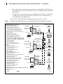
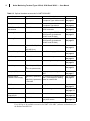
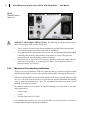
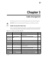
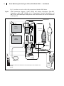
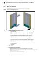

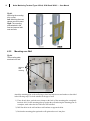
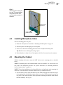
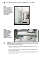


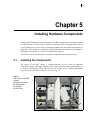
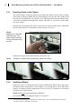
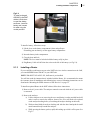
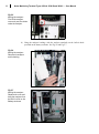

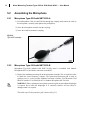
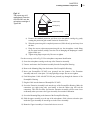
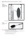
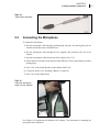
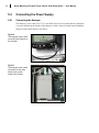
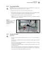
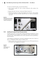
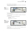
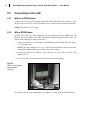
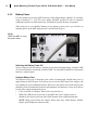
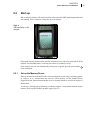
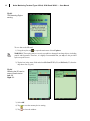
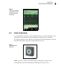
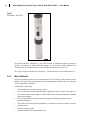
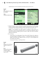


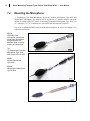
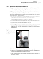


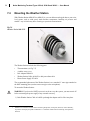
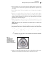
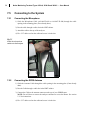
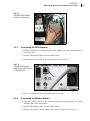

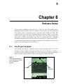
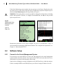

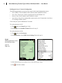
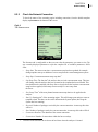
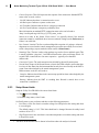
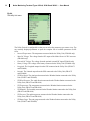

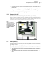


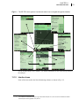
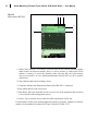
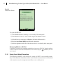
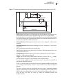
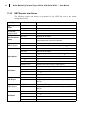
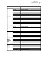
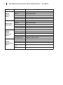
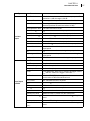
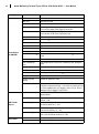
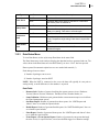

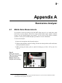
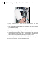
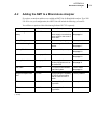
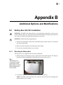

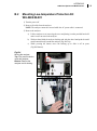
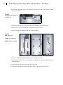
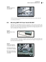


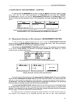
![[Italian] Documentazione Tecnica: 2250 Light con](http://vs1.manualzilla.com/store/data/006160524_1-f69e9fdf78c2a064fca03fcd4c87c082-150x150.png)


![[Italian]Documentazione Tecnica: Analizzatori portatili](http://vs1.manualzilla.com/store/data/006162879_1-c9f956b7ab0328a00893d3c6418e422c-150x150.png)