1
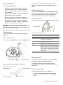
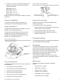
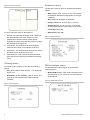
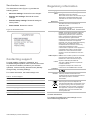
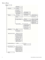
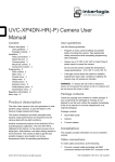
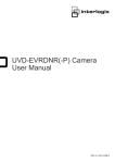
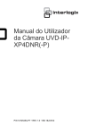
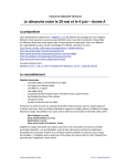
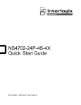
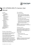
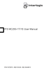
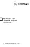
UVD-XP4DNR(-P) Camera User Manual
Content
Preface 1 Safety terms 1 Product description 1 Features 1 User guidelines 2 Components 2 OSD control pad 2 Installation 2 Cable connection 2 Camera installation 3 Angle adjustment 3 Focus adjustment 3 Connect the monitor 3 Programming 3 Navigation 3 Main menu 3 Presets menu 4 Setup menu 4 Viewing menu 6 Exposure menu 6 White balance menu 6 Save/restore menu 7 Contacting support 7 Regulatory information 7 Menu Map 8 •
a basic knowledge of electrical wiring and lowvoltage electrical connections.
Note: A qualified service person, complying with all
applicable codes, should perform all required hardware
installation.
Safety terms
These terms may appear in this manual:
CAUTION: Cautions identify conditions or practices that
may result in damage to the equipment or other
property.
WARNING: Warnings identify conditions or practices
that could result in equipment damage or serious
personal injury.
Product description
The UVD-XP4DNR(-P) (rugged dome) color video
cameras is a 24 VAC/12 VDC model. The cameras are
equipped with a digital signal processor (DSP) for
processing the video signal.
Preface
Features
This is the UVD-XP4DNR(-P) Camera. This document
includes an overview of the product and detailed
instructions explaining:
Camera features include:
•
Next-generation XPosure technology.
•
how to connect the camera; and
•
Improved low-light performance and color balance.
•
how to program the camera.
•
540 TVL lines color.
•
how to adjust the camera angle and focus
•
Dynamic range 95 dB (typical), 120 dB (maximum).
•
Preset modes optimized for various environments.
•
On-screen display interface.
To use this document effectively, you should have the
following minimum qualifications:
•
a basic knowledge of CCTV systems and
components; and
P/N 1079204A-EN • REV R1.0 • ISS 20DEC11
User guidelines
Plug the monitor output RCA into the video monitor
output and connect the monitor output BNC to the TV
monitor.
Use the following guidelines:
•
Program as many camera settings as possible
before mounting the camera. Take appropriate
safety precautions while completing programming
after installation.
•
Always use a 12 VDC or 24 VAC UL listed Class 2
power supply to power the camera.
•
Do not use the camera outside the temperature
range specifications: -57 to 122°F (-50 to +50°C).
•
OSD control pad
The on-screen display (OSD) control pad (Figure 3) is a
five-direction joystick that provides the ability to manually
control the camera functions. Table 1 below lists the
OSD control pad functions and describes their use.
Figure 3: OSD control pad
If the light source where the camera is installed
experiences rapid, wide- variations in lighting, the
camera may not operate as intended.
WARNING: To reduce the risk of fire or electronic
shock, do not expose the camera to rain or moisture and
do not remove the cover or back.
OSD control pad
Components
Table 1: OSD control pad controls
Figure 1 shows the main components of the rugged
dome unit.
Figure 1: Rugged dom2e unit
Lens body
Pad directions
Description
Up
Moves the cursor upward to select an item
Left
Moves the cursor left to select or adjust the
parameters of the selected item.
Right
Moves the cursor to the right to select or adjust the
parameters of the selected item.
Down
Moves the cursor downward to select an item.
Enter
Press the center of the control pad to
display the Setup menu. If the selected item
has its own menu, press the control pad to
enter a submenu. Press the control pad for
2 seconds to save all settings and exit the
Setup menu.
Bubble
Installation
Camera body
OSD control
pad
Video monitor output
Figure 3 shows the monitor output components.
This chapter provides information on how to install the
camera and adjust camera angle and focus.
To install the camera you will need to prepare the
mounting surface, make cable connections, and mount
the camera.
Figure 2: Monitor output cable
Cable connection
To make cable connections, do the following:
A. Monitor output BNC
2
B. Monitor output RCA
1. Connect a coaxial cable from the camera’s BNC
connector to a CCTV monitor or video recording
device.
UVD-XP4DNR(-P) Camera User Manual
2. Connect a 12 VDC or 24 VAC power supply to the
power input. The label on the camera gives the
following information:
Figure 5: Zoom and focus adjustment
Red cable. Power in.
Black cable. Power in.
White cable. Video out.
Black cable. Video ground.
Zoom ring thumbscrew for
VA2 and focus ring for VA9
lens
Note: For AC24V or DC12V, Black or Red may be used
for ground.
Focus ring thumbscrew for
VA2 and zooming ring for VA9
lens
Camera installation
Connect the monitor
To mount the camera, attach the camera to the
mounting surface using the appropriate fasteners.
Program the cameras by attaching a standard video
monitor to the system.
To connect the monitor, do the following:
Angle adjustment
To adjust the horizontal angle of the platform up to 180
degrees, turn the platform (Figure 4).
To adjust the horizontal angle of the rotor up to 350
degrees, turn the rotor on the platform (Figure 4).
1. Plug the monitor output cable (Figure 2) to the video
monitor output connector (Figure 1).
2. Connect the BNC cable to the video monitor.
3. Press Enter (see OSD control pad on page 9) to
display the Setup menu.
To adjust the vertical angle of the platform up to 90
degrees, turn the platform (Figure 4).
Programming
Figure 4: Camera adjustment
This chapter describes how to navigate the programming
menus to adjust the camera settings.
Platform horizontal adjustment
Navigation
Platform vertical
adjustment
Rotor horizontal
adjustment
Focus adjustment
To adjust the camera zoom and focus, see Figure 5 and
do the following:
1. Loosen the zoom ring thumbscrew.
2. Turn the zoom ring to set the desired zoom.
3. Tighten the zoom ring thumbscrew.
4. Loosen the focus ring thumbscrew.
5. Turn the focus ring to set the desired focus.
6. Tighten the focus ring thumbscrew.
UVD-XP4DNR(-P) Camera User Manual
To access and navigate the menus, press and hold the
center of the OSD control pad (Figure 3). Press Up or
Down on the control pad to move between items, and
press Enter (center of the control pad) to select the item.
Press Right or Left on the control pad to select the
different options available for the item.
You can return to the previous menu from any of the
menus (except the Main menu) by selecting the Previous
page option.
Main menu
The Main menu (Figure 6) provides the following
options:
•
“Presets menu” en page 4.
•
“Setup menu” en page 4.
•
“Viewing menu” en page 6.
•
“Exposure menu” en page 6.
•
“White balance menu” en page 6.
•
“Save/restore menu” on page 7.
3
•
Exit menu (exits the menu system).
Figure 7: Setup menu
There is a menu map provided on the back page of the
manual.
Figure 6: Main menu
Camera ID setup menu
The Camera ID setup menu (Figure 8) provides the
following options:
Presets menu
•
ID display (off or on).
•
Camera ID. Press Right to move the cursor to edit
the camera ID. Press Up or Down to select the ID.
When complete, press Up or Down to leave the
editing field.
•
ID position (up-left, up-center, up-right, down-left, or
down-left).
The Presets menu options include:
Normal. This is the camera default preset for general
lighting conditions out of the box. This mode supports 14
bits of dynamic range and gives priority to rendering the
highlights in the scene.
Indoor. This preset supports 16 bits of dynamic range
and gives priority to rendering the shadows in the scene.
Figure 8: Camera ID setup
Outdoor. This preset offers the highest dynamic range
of 17 bits and gives priority to rendering the highlights in
the scene.
Flickerless. This mode uses line lock to eliminate phase
roll under fluorescent lights. It must be used with a 24
VAC power supply.
NTSC50Hz. This mode uses a DC iris lens to reduce
phase roll under fluorescent lights. This mode will not
function correctly with a manual iris lens.
Setup menu
Sync menu
The Setup menu (Figure 7) provides the following
options:
The SYNC option in Setup menu (Figure 8 on page 19)
provides the following INT or LL (LINE LOCK) options:
•
“Camera ID setup menu” below.
•
“Sync menu” below.
INT. Internal sync. Used with DC power input to reduce
the phase roll of fluorescent lights.
•
“Motion detection setup” on page 5.
•
WDR setup (safe area, center spot, lower 1/3, or full
screen).
4
LL. Line lock. Used to sync video for AC power input so
that the sync matches the frequency of the power input
to eliminate the roll caused by fluorescent lights. (Figure
10)
UVD-XP4DNR(-P) Camera User Manual
Figure 9: Line lock menu
Figure 11: Motion detection menu
Motion detection setup
A motion detection alarm refers to an alarm triggered
when the camera detects a motion. The Motion detection
setup display (Figure 10) provides the following options:
•
“Motion options” ci-dessous.
•
“Setup motion zone” ci-dessous
Figure 10: Motion detection zone setup
Motion detection menu
The Motion detection menu (Figure 11 above) provides
the following options:
•
Motion Threshold. Set the level of sensitivity of the
motion detection.
•
Digital zoom. Determine how far in the camera
zooms upon alarm. By default, the camera zooms to
the center of the screen.
•
Digital pan. Adjust where the camera zooms upon
alarm. Move the slider to the left to pan left, and to
the right to pan right.
•
Digital tilt. Adjust where the camera zooms upon
alarm. Move the slider to the left to tilt down, and to
the right to tilt up.
Setup motion zone
Motion options
The camera will monitor for motion in the area defined in
the boxes defined in this submenu (Figure 12 below).
When motion is detected in this area, the camera issues
an alarm and zooms in.
Off. Motion detection is disabled.
Motion det. Motion detection is enabled, with default
motion settings. Enter the submenu (Figure 11) to
change the settings (see “Motion detection menu”
below). When motion is detected, the word “Alarm” is
displayed on the top left of the screen, and the image is
zoomed, tilted, and panned to the area setup in Setup
alarm zone.
UVD-XP4DNR(-P) Camera User Manual
Figure 12: Motion zone setup
5
Figure 13: Alarm zone setup
Exposure menu
The Exposure menu (Figure 15) provides the following
options:
To set up the alarm zone, do the following:
1. Choose one of the options Adjust Zone 1/2/3/4 from
the Setup Motion Zone menu (Figure 12). The
selected zone will have a thick border and be
highlighted in white. Press the arrow keys to change
the selected zone (Figure 13).
•
AGC (medium, high, custom, or low). The camera
automatically adjusts the image quality in low light
conditions.
•
AE preferences (highlights or shadows).
•
Range control (low, normal, high, or custom).
•
Shutter limit (x2, x4, x8, x16, x32, or off). A fast
shutter speed captures clear images of fast action.
•
Frame RPT (OFF/ON).
•
B/W Control (OFF/ON).
Figure 15: Exposure menu
2. Press Enter. The selected zone becomes green.
Press the arrow keys to increase the zone area.
3. Press Enter. The selected zone becomes red. Press
the arrow keys to shrink the zone area.
4. Press Enter for a few moments to leave the Alarm
Zone Setup menu and return to Motion Zone Setup
menu.
Viewing menu
The Viewing menu (Figure 14) provides the following
options:
•
•
Flip. (OFF, HORIZ, VERT, BOTH) Turn horizontal
flip off or on.
Resolution. (HIGH, NORMAL) High or normal. The
High option over-sharpens the image for higher
resolution.
White balance menu
The White balance menu (Figure 16) provides the
following options:
•
Mode (ATW or PTL). ATW mode is automatic trace
white balance. In PTL mode you can set a specific
white balance.
Figure 16: White balance menu
Figure 14: Viewing menu
6
UVD-XP4DNR(-P) Camera User Manual
Save/restore menu
The Save/restore menu (Figure 17) provides the
following options:
•
Save user settings. Saves all current changes.
•
Restore user settings. Discards all current
changes.
•
Restore factory settings. Resets all settings to
factory levels.
•
Regulatory information
Copyright
Trademarks and
patents
Manufacturer
FCC compliance
ACMA compliance
Contacting support
Table 2: Technical Support
Europe, Middle East and Africa
W
Select Contact Us at www.utcfssecurityproducts.eu
North America
T
+1 855.286.8889
E
[email protected]
Australia
E
UTC Fire & Security Americas Corporation, Inc.
2955 Red Hill Avenue, Costa Mesa, CA
92626-5923, USA
Authorized EU manufacturing representative:
UTC Fire & Security B.V.
Kelvinstraat 7, 6003 DH Weert, The Netherlands
Figure 17: Save/restore menu
For contact information, see www.interlogix.com
Interlogix, UltraView brand and logo are
trademarks of UTC Fire & Security.
Other trade names used in this document may be
trademarks or registered trademarks of the
manufacturers or vendors of the respective
products.
Reset camera. Resets the camera.
For help installing, operating, maintaining, and
troubleshooting this product, refer to this document and
any other documentation provided. If you still have
questions, contact us during business hours (Monday
through Friday, excluding holidays).
© 2011 UTC Fire & Security. All rights reserved.
Canada
Class A: This equipment has been tested and
found to comply with the limits for a Class A
digital device, pursuant to part 15 of the FCC
Rules. These limits are designed to provide
reasonable protection against harmful
interference when the equipment is operated in a
commercial environment. This equipment
generates, uses, and can radiate radio frequency
energy and, if not installed and used in
accordance with the instruction manual, may
cause harmful interference to radio
communications. Operation of this equipment in
a residential area is likely to cause harmful
interference in which case the user will be
required to correct the interference at his own
expense.
Notice! This is a Class A product. In a domestic
environment this product may cause radio
interference in which case the user may be
required to take adequate measures.
This Class A digital apparatus complies with
Canadian ICES-003.
Cet appareil numérique de la classe A est
conforme à la norme NMB-0330 du Canada.
Certification
European Union
directives
N4131
12004/108/EC (EMC directive): Hereby, UTC Fire
& Security declares that this device is in
compliance with the essential requirements and
other relevant provisions of Directive
2004/108/EC.
2002/96/EC (WEEE directive): Products marked
with this symbol cannot be disposed of as
unsorted municipal waste in the European Union.
For proper recycling, return this product to your
local supplier upon the purchase of equivalent
new equipment, or dispose of it at designated
collection points. For more information see:
www.recyclethis.info.
[email protected]
Contact information
For contact information see: www.interlogix.com or
www.utcfssecurityproducts.eu.
UVD-XP4DNR(-P) Camera User Manual
7
Menu Map
8
UVD-XP4DNR(-P) Camera User Manual