1
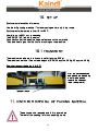
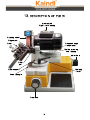
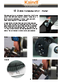
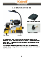
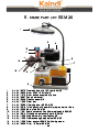
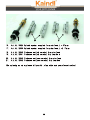
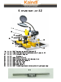
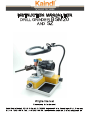
INSTRUCTION MANUAL FOR DRILLGRINDER BSM20 AND SZ Original manual Please keep for further use! Kaindl-Schleiftechnik REILING GmbH, D-75203 Königsbach-Stein, Remchinger Str. 4, Germany Tel.: +49 7232/4001 -0, Fax.: +49 7232/4001 -30, Internet: www.kaindl.de, E-Mail: [email protected] CONTENT EC-Declaration of conformitiy Description of product Description of function Basic equipment / Accessory BSM 20 / SZ Technical data BSM 20 / SZ General safety advice Description of safety symbols Basic safety operations Request to the operating personal Special kind of danger Set up / Transport / Hints for disposal of packing material Start up / Checks before first start up Operation BSM 20 Description of parts Grinding of right hand drills Grinding of left hand drills Web thinning Thinning Split-Point Four facet shape / cutters Grinding of stepped drills Grinding of carbide drills (Widia) - drills Grinding of sheet metal drills Grinding of wood drills Grinding of Forstner drills Grinding of the outer cutting edges Countersink sharpening device SVR 20 Alignment of the sharpening device SVR 20 Montage + dressing the grinding wheel before first operation / adjustment of the grinding wheel protection Change the grinding wheel Dressing of grinding wheel User manual SZ Operating part (On/Off switch) Description of the machine Description of the machine / wheel dressing Operation of the SZ Maintence / Wear parts BSM 20 / SZ / Repairs Warranty / Disposal of the machine Spare part lists BSM 20 / SZ 2 3 4 5 5 6 7 8 9 10 10 11 12 13 14 15 17 18 19 20 21 22 23 24 25 26 27 28 29 30 31 32 33 34 35 36 37 38 EC DECLARATION OF CONFORMITY The manufacturer: Kaindl-Schleiftechnik Reiling GmbH Remchinger Straße 4 75203 Königsbach-Stein Germany Herewith declares tht the machine decribed hereafter: Grinding machine Typ: BSM 20 + SZ Refers to the security and health requirement of EC-Machine instruction (2006/42/EC) the following EC instructions: EC-instruction EMV (2004/1 08/EC) Applied harmonised norms: EN ISO 12100; EN ISO 13857; EN ISO 137321; EN 60204 Part 1; EN 6100061; EN 6100062; EN 6100063; EN 6100064 Changes in engineering design, having effect on technical data stated in this operation manual and directed use, therefore change the character of the machine substanially make this declaration of conformity invalid! These documents had been made up by: Reinhard Reiling Kaindl-Schleiftechnik Reiling GmbH Remchinger Straße 4 75203 Königsbach-Stein Königsbach-Stein dated 29.1 2.2009 .................................................. Reinhard Reiling, General manager 3 1 . DESCRIPTION OF PRODUCT 1 .1 DIRECTED USE The drill grinding machine BSM / SZ is exclusivly determined for occassional grinding of spiral-, step-, wood- and Forstner drills as well as sheet metal-, stone-, (carbide) drills, turning tools and countersinks. For other use than listed here, the machine is not designed for and is regarded as a matter of adverse use! The directed use includes also reading this operation manual, as well as keeping all containing directions of use - especially the safety information. In case the drill grinding machine BSM 20 / SZ is not used as per the intended purpose, a save operation cannont be granted. For all personal- and material damages, arising by not intended use, not the manufacturer, but the user of the Kaindl BSM 20 / SZ is reponsible! 1 .2 PREDICTABLE WRONG APPLICATION The use as a table machine for manually guided grinding of workpieces, such as chisel, sheet metal, screwsdriver, etc. is not allowed! 4 2. DESCRIPTION OF FUNCTION This mobile drill grinding machine made by Kaindl is unique as to its design and offers a genuine alternative to bigger and considerably more costly equipments. Owing its solid construction, its high precission, its small space requirement and its favourable price, the Kaindl grinding machine is an indispensable auxillary equipment and a real measure of economy even for single operation sections and for smaller workshops. The machine facilitates the adjustment and the resharpening of twist drills to that extend, that everybody will be able to resharpen drills with every lib angle that is imaginable. Form the prism reversing process results automatically the highest precision and cutting egde symmetry. The well planned conception and the possibility of an easy change of all party subject to wear, preserve the Kaindl drill grinding machine as an indespensable aid in your work-shop. Even after many years of employment. 2.1 BASIC EQUIPMENT BSM 20 / SZ BSM 20: Range 1 - 20 mm (prism), complete with CBN-grinding wheel and optical lens LED lighted. SZ: with corundum cup wheel and grinding table with electro magnet, diamond cup wheel, diamond dresser and optical lens LED lighted. 3. ACCESSORY AND SPARE PARTS BSM 20 / SZ 1 7073 CBN grinding wheel ø 1 25 mm grit B1 26/3, covered on 3 sides, width 20 mm 1 6490 CBN grinding wheel ø 1 25 mm grit B76/3, covered on 3 sides, width 20 mm (standard) 1 7556 CBN grinding wheel ø 1 25 mm grit B46/3, covered on 3 sides, width 20 mm 1 0895 Corundum grinding wheel 1 25 x 20 x 20 grit 60 (coarse) 1 0890 Corundum grinding wheel 1 25 x 20 x 20 grit 80 (standard) 1 0891 Corundum grinding wheel 1 25 x 20 x 20 grit 1 80 (very fine) 1 0893 Corundum grinding wheel 1 25 x 05 x 20 grit 1 00 (HSS wood bits) 1 0896 Corundum cup wheel grit 60 (standard) for SZ 1 0897 Corundum cup wheel grit 80 (medium) for SZ 1 0898 Corundum cup wheel grit 1 00 (fine) for SZ 1 5422 Grinding wheel support 1 4581 Diamond grinding wheel D 76, covered on 3 sides for carbide wood drills 1 4580 Diamond grinding wheel D 76, covered on 3 sides for carbide drills 11 223 Diamond cup wheel D 1 26 (standard) for SZ 1 0887 Diamond cup wheel D 76 (fine) for SZ 1 0906 Universal clamping device for single-lip cutters, cut off tools, etc. for SZ 1 0889 Magnetic depth stop for cutters 1 0875 Countersink sharpening device SVR 20 with collet 1 0 mm 1 0877 Collet 6 mm for SVR 20 1 0878 Collet 8 mm for SVR 20 1 0879 Collet 1 2 mm for SVR 20 1 0901 Morse taper sleeve MK1 1 0902 Morse taper sleeve MK2 5 4. TECHNICAL DATA BSM 20 and SZ with magnetic table Dimension drill grinding machine BSM 20: LxDxH Weight 370 x 350 x 270 mm 22 Kg Dimension SZ : LxDxH Weight 500 x 420 x 31 0 mm 40 Kg Movement Drill grinding machine: Prism clamping range Motor feed Prism feed Clearance angle Top angle Grandient of spindles Grinding wheel 1 - 20 mm max. 65 mm max. 45 mm stepless adjustable stepless adjustable from 60°-200° 3 mm ( 1 scale line = 0,03 mm) Corundum grinding wheel 1 25 x 20 x 20 grit 80, Hardness M, Vmax = 35 m/s ; n = 5400 RPM Noise emission < 70 dB(A); Emission- acoustic pressure at workplaces (ear level) as per DIN EN ISO 11 204 Operation condition Sharpening of a HSS 1 5 mm dia drill Run out time of grinding wheel approx. 1 0 seconds Grinding table Movement Table size Swing range table Grinding wheel Noise emission Electrical connection: Total value Degree of protection 305 mm 1 70 x 1 00 mm stepless +20° to -60° Corundum cup wheel 1 25/1 05 x 40 x 20 grit 60, Hartness J , Vmax = 30 m/s ; n = 4600 RPM < 70 dB(A); Emission- acoustic pressure at workplaces (ear level) as per DIN EN ISO 11 204 230 Volt / 50 Hz / 1 30 Watt / 2800 U/min IP 54 Technical changes may be done without notification! 6 5.1 5. GENERAL SAFETY ADVISE DUTY OF TAKING CARE BY THE USER The drill grinding machine BSM 20 / SZ has been designed and constructed under consideration of an endangering analysis and careful selection of observed harmonized norms, as well as further specifications. The BSM 20 / SZ meets the state of the art and grants a maximum of safety. This safety can only be achived in daily work, when all necessary steps are taken. It is the duty of taking care by the user to plan and control these steps. The user expecially has to take care that: • • • • • • • the BSM 20 / SZ is used as directed (see chapter "description") the machine is used in flawless workable condition, especially that the safety installations are checked requested personal security equimpent for the operator is available and used the operation manual is always in a readable condition, complete and available near the machine BSM 20 / SZ the drill grinding machine BSM 20 / SZ operated only by personnel that knows the contained operating instructions and the safety information Carrier active implants (pacemakers) must meet the safety distance of 20 cm between the magnetic table of the sharpening center SZ and the position of the implant all safety and warning instructions are not removed from the machine and kept readable Persons having not familiarized with the security advises, described herein, can't operate the machine . 7 6. DESCRIBTION OF SAFETY SYMBOLS In this instruction manual, the following safety symbols are used. These symbols shall attract the readers attention to the text next to the symbols. These symbols indicate that there is an existing danger to live and health of persons. Protect eyes while grinding, against kicked around particles General danger Before changing the grinding wheel or moving disconnect from electric current The lens cover of the magnifying lamp has to be closed after use : Caution: Lens cover always must be kept close when not in use (danger of fire by sunbeam) 8 7. BASIC SAFETY OPERATIONS Keep information on-hand: This instruction manual has to be kept beneath the machine. It has to be granted, that all persons working on the machine have access to the instruction manual. Additionally there should be provided special advises in sence of a safe workplace. All safety and operation labels on the machine should be keep in good condition and readable. Damaged or non readable labels have to be replace immendiately. These symbols indicate that there is an existing danger to live and health of persons. For all grinding works with BSM 20 / SZ always wear safety glases. Grinding dust may hurt your eyes. Only remove the grinding wheel protection for changing the wheel. Never operate the machine with complete grinding wheel protection. Before changing the grinding wheel or moving, disconnect from electric current! 9 8. REQUEST TO THE OPERATING PESONAL Only persons who are familiar with this manual are allowed to work with this machine. 9. SPECIAL KIND OF DANGER Before starting the machine, the following jobs have to be done: • • • • • • Check the machine for visible dammage and eliminate ascertainend defects. The operation of the machine is only permitted in flawless condition. Electrical connections have to be checked regularly. Fix loose connection. Dammages electric cables have to be immediately replaced an electrician. Never clean electric parts with water or simmilar liquids. Changes on the machine: Due to safety reasons changes on the machine without permission are nor allowed. Only use original - spareparty, - original wear parts original accessories. These parts are ecspecially designed for this machine. 10 1 0. SET UP Environmental conditions for set up Use the drill grinding machine / Tool sharpening center only in dry rooms. Environmental temperature from +5 to +50°C. Humidity: up to 90%, not condensing The BSM 20 / SZ is a table version. Pay attention that the machine has a safe stand on the work table. The place has to grant a vibration free running on the machine . 1 0.1 TRANSPORT The machine is delivered in a box on a pallet (approx. 50 Kg). The machine has to be lifted outside diagonal, BSM 20 approx. 25 Kg; SZ approx. 40 Kg Remove transport locks (only for SZ) After you have unpacked and placed the machin on a work table, please remove the transport locks. (see picture) Transport locks 11 . HINTS FOR DISPOSAL OF PACKING MATERIAL The carton can be recycled and is for paper waste. The rest of the packing is for non recycling waste. 11 1 2. START UP In order to prevent dammage to the machine or injuries, please pay attention to the following items before starting: • • • • Check that all tools or part not belonging to the machine have been removed before starting. Sound test, assembly and removal of the grinding wheel (see page 28) Also read the chapter "General safety advise". Wear protective glasses. 1 2.1 • • • CHECKS BEFORE FIRST START UP Check electric components for dammage (sight check). Check guidance for soft turning. Check fixed parts. 12 1 3. DESCRIPTION OF PARTS motor switch Right - Left Running Grinding wheel Wing screw Prism Clearance angle adjustment Fixation screw e.g. web thinning Motor feed Prism rest Clamping lever Prism support Scale tip angle Prism feed 13 1 4. GRINDING OF RIGHT HAND DRILLS Alignment of drill: The reversing prism has a clamping range from 220 mm. Open the prism by turning the knurled screw. Place the drill in the prism. main cutting edge Let project the drill around approx. 2025 mm outside the prism clamp. Close the prism carefully with the knurled screw, pay attention the the drill still can still be turned. Align one cutting edge between both graduation lines (see picture). Now tighten the prism with the knurled screw by hand (without use of force). The drill is know aligned and ready to sharpen. Slide prism with the drill onto the prism support and fix with the wing screw. Adjust the requested top angle (standard 118°) on the prism support an fix with the clamping lever. • • right part-scale: support to right stop dog (slot) and adjust clearance angle. left part-scale: support to left stop dog (slot) and adjust clearance angle. It does not matter which part-scale you use. The clearance angle is adjusted by the scale for the clearance angle. • Direction 3 = more clearance angle • Direction 1 = less clearance angle The clearance angle is adjusted by the clearance angle scale. 1 5. GRINDING OF THE DRILL Move the drill to the front side of the grinding wheel, by using the prism feed and the motor feed. By carefully feeding with the prism feed and meantime turning the prism upside down, grind the first cutting edge completely. Note the graduation No. on the scale, feed back, remove and turn the prism, place again in the prism support, fix it and grind the second cutting edge to the same graduation as noted. 14 1 5.1 GRINDING OF LEFT HAND DRILLS Grinding wheel: depending on sort of drill: use corundum and diamon wheel. Adjustment on the machine. Tip angle: 11 8° For grinding of left hand drills, the prism rest an clearance angle adjustment hast to be changed (Picture A). A Clamping screw Remove the prism support from the clearance angle adjustment and screw together on the provided fixation threat (L) for left hand drills (Picture B). R L B 15 Let project the drill approx. 15 mm out of the prism. Align one cutting edge parallel to the gaduation mark for left hand drills (Picture). Graduation line for left hand drills Adjust the request clearance angle on the scale (Picture). Applicative scale range for left hand grinding: 2-3. 2 = slight clearance angle 3 = high clearance angle GRINDING OF THE DRILL Move the drill to the front side of the grinding wheel, by using the prism feed and the motor feed. By carefully feeding with the prism feed and meantime turning the prism upside down, grind the first cutting edge completely. Note the graduation No. on the scale, feed back, remove and turn the prism, place again in the prism support, fix it and grind the second cutting edge to the same graduation as noted. 16 1 5.2 WEB THINNING OF DRILLS Keep the prism support, as described before. Turn the clearance angle adjustment to 1 (see picture below). Fix the turning mechanism in hole C of the fixation plate (see picture below). Shift the complete prism tretle to the left stop, adjust on mark A1. By using the motor- and prism feed, grind inside the drill behind the drill cutting edge. Note the graduation No. on the prism feed scale and go back for 3 complete turns. Do not chance the position of the motor feed. Open the clamping lever, reverse the prism, fix again and thin the web of the other side. Lock points A: Lock point for cutter, carbide drill. crossfacet shape, four surface shape C B: Lock point for back or free B C: Lock point for web sharpening thinning A Clearance angle to max minus Prism rest to Pos. A1 17 1 5.3 WEB THINNING SPLIT - POINT After sharpening, do not chance the position of drill in the prism. Place clearance angle to postion 2 (see picture 1 ). Fix the swivel mechanism in boring C (see picture 2). Place the tip angle to A2 (see picture 3). In combination of prism feed and motor feed, sharpen the first side of the drill on-hook (see picture 4). Note the graduation mark of the motor feed and then move back to the left away from grinding wheel. Turn the prism for 180° and move forward to the same graduation mark as before. The drill should look like on the picture above. Picture 1 Picture 2 C B A Picture 3 Picture 4 18 1 6. GRINDING OF CROSS CUTTING OR 4 FACET DRILLS Depending of the drill is made of, use the corresponding grinding wheel. Align one cutting edge parallel to both graduation lines (see picture). Project the drill approx. 20 mm outside the prism. Fix the turning mechanism in hole A (see picture below). Adjust the top and clearance angle to your specifications. Grind the first side over the right edge of the grinding wheel by feeding the prism and moving with the motor feed. The second side is ground with the same adjustments. For grinding the back, fix the turning mechanism in hole B. The grinding operation is the same as for the first two cutting edges. 1 6.1 GRINDING OF A CUTTER Align the cutter to the straight line of the prism Cutter grinding is slightly different to cross facet grinding. But the adjustment and alignment is identical to the 4 facet drill. The dirrerence in only the top angle adjustment. Here use 180°185° (see picture below). The shaprening procedure is identical. For cutters with more then two cutting edges use the magnetic depth stop, listed under special accessoires. For cutters with odd. cutting edges (e. g. 3-cutters) each cutting edge has to be adjust separately. Having cutters with even numbers of cutting edges, the opposite is cutting edges can by ground by reversing. C B A A: Locking for main cutting edge B: Locking sharpening for free Prism rest 180° 185° 19 1 7. STEP DRILLS Grinding wheel: Depending on the drill, use corundum or diamond wheel. ATTENTION! Only step drills with two steps can be sharpened! Grinding of the 1 . Stufe (tip): Alignment and sharpening as for right hand drills (see picture below). The second step is adjusted in lengh and side direction as twist drills. The tip angle is adjusted on the prism support. Clearance angle as per your request. Grind the second step over the right side of the grinding wheel. Alignment of the tip Alignment of the step 20 1 7.1 CARBIDE DRILLS Use diamond wheel! (option) Change of the grinding wheel, see page 29. Grinding of carbide drills depending on shape of cutting edge use the 4 facet shape or twist drills. The sharpening of stone drills with 4 facet shape is same as describted on page 1 9. The sharpening of stone drills with standard twist drill shape is same as described for right hand drills (see page 1 5). Alighn main cutting edge straight to line Align main cutting edge between both graduation marks Twist drill shape 4 facet shape 21 1 7.2 SHEET METAL DRILLS (with center tip) Grinding wheel: Corundum, dress the right side of the wheel with an angle of approx. 45°. Use the grinding wheel dresser to dress the requested shape. Adjustment of drill Prism rest Adjustment of the drill in the prism: • • Adjust the main cutting edge parallel to both graduation line on the prism (see pic.) Project the drill around 35 40 mm outside the prism Adjustment of the machine: • • Top angle: 1 80° left Clearance angle: to your requirement Grinding operation: By carefully feeding the prism towards the wheel and meantime swivelling the prism, grind the first side of the cutting edge, then move with the motor feed to the centre tip of the drill bit and grind over the tip using the 45° dressed side of the grinding wheel. Note the No. on the scale of the prism feed and move back, remove the prism of the prism support, reverse, fix again in the support and grind the second cutting edges to the same graduation No. Now the second side of the tip is ground centrically. The tip thinning is identical as for twist drills (see page 1 8). 22 1 7.3 GRINDING OF WOOD DRILLS Grinding wheel: depending of the material the drill is made of, thin corundum or thin diamond wheel. Adjustment of the drill in the prism: • • Main cutting edge parallel to both graduation lines project the drill: approx. 35 - 40 mm outside the prism Adjustment on the machine: • • Tip angle: 1 80° left Clearance angle: to your requirement Grinding of the drill: By carefully feeding the prism towards the wheel and meantime swivelling the prism, grind the first side cutting edge, then move with the motor feed to the centre tip of the drill bit and grind over the tip using the 45° dressed side of the grinding wheel. Note the No. on the scale of the prism feed and move back, remove the prism of the prism support, reverse, fix again in the support and grind the second cutting edge to the same graduation No. Now the second side of the tip is ground centrically. Move with the motor feed to the left and grind the outer cutter with the dressed side od the grinding wheel. The second outer cutter grind with the same setting. The tip thinning is identical as for twist drills (see page 1 8). 23 1 7.4 GRINDING OF FORSTNER DRILLS ATTENTION! Only the open types can be ground! Grinding wheel: depending on the material the drill is made of, use a thin corundum or thin diamond wheel. Adjustment of the drill in the prism: The outer and main cutting edges are placed directly on the grinding wheel. Adustmen on the machine: • • • Tip angle: 1 80° left Clearance anglel: to your requirement Turning mechanism: fix in hole A Grinding of the main cutting edges: • • • Align the main cutting edge to the grinding wheel, so that the outer edge cannot be hurt by the grinding wheel. Grind the first main cutting edge from the inside to the outside Reverse the prism and grind the second main cutting edge from the outside to the inside 24 1 7.5 GRINDING OF THE OUTER CUTTING EDGES Adjustment on the machine: • • Tip angle: 1 80° left Clearance angle: to your requirement Align outer cutters to the grinding wheel and grind by reversing. 25 1 8. COUNTERSINK SHARPENING DEVICE SVR 20 C B Fix in hole A A 26 1 9. COUNTERSINK SHARPENING DEVICE SVR 20 For sharpening countersinks with the BSM 20 / SZ, this special accessory type SVR 20 is required. Arrest the turning mechanism on the BSM 20 drill sharpening machine in hole A (see picture on page 26). Fix the stepless clearance angle adjustment on the third graduation mark from above (see picture). The prism rest fix at 90° (see draw). Place your countersink inside the collets of the SVR 20 and align one cutting edge parallel to the line on the SVR 20, below the collets nut (see also drawing E). With the screw I and J (see the drawing on the right) you can adjust the distance between the SVR 20 and the grinding wheel. For bigger countersinks the SVR is positioned backwards and can only fixed with one screw on the adaptor plate. Slide the SVR 20 on the turning mechanism to the stop dog and fix with the clamping screw. By turning the hand wheel of the SVR 20 clockwise and carefully moving forward with the prism feed on the BSM 20 you can sharpen the flutes of your countersink. It is absolutley recommended grinding with a clean and parallel dressed grinding wheel. For one-flute countersinks you have to mount the special cam (Art No. 1 0605) for adjusting see drawing F. ATTENTION! When you align the tip of countersink parallel to the graduation line on the SVR 20, take care that the bigger hole is on this side. tip collet nut graduation mark collet nut graduation mark 27 collet nut graduation mark 20. MOUNTING AND DRESSING OF THE GRINDING WHEEL BEFORE THE FIRST START After you have moved the machine to its final place take the grinding wheel and make a sound and optical check. Then mount the wheel on the support. Mounted wheel with support Grinding support wheel Now slip the mounted wheel with support in the motor shaft (see page 31 ). After you have checked the correct position of the wheel and the grinding wheel protection cover you have to dress the wheel (see page 30). Only when you follow these advises, a safe and correct working with the machine is granted. PROTECTION ADJUSTMENT By opening the threated pin you have the option to adjust the grinding wheel cover. After correct adjustment please tighten the threated pin again. Threated pin 28 21 . CHANGE THE GRINDING WHEEL 1. Pic 2 Pic 1 Pic 3 Notch Threated pin 2. Before changing the grinding wheel, disconnect from electric net. Loosen both hat cap screws (1 + 2) with a 1 0 mm engineers wrench and remove the grinding wheel cover to the left (picture 1 ). Now loosen the screw in the middle of the wheel support with the hexagon socket wrench SW 4,0 (comes with the machine) (picture 2). Now you can tear the grinding wheel with support with the included key and change the grinding wheel. By slinding the support on the motor shaft, pay attention that the threated pin of the support is in the notch of the motor shaft (picture 3). Now fix the haxagon socket screw SW 4,0 and make sure that the cover is mounted correctly. Never use the corundum cup wheel for drill grinding. The grinding wheels habe to cmply with norms EN 12413 or EN 13236. After the wheel change, start a text run of minimum one minute. The BSM 20 is not allowed to be operated without a correctly mounted grinding wheel cover. 29 22. DRESSING OF THE GRINDING WHEEL Fix clamping screw in hole A Place the dresser Part No, 1 0908 in the prism, in order the rotating front part can still be turned. Fix the clearance angle to No. 2 and set the angle on the support rest to 118°. Now fix the clamping screw in hole A (see picture ahead). Now carefully move the prism feed toward the wheel so the rotating diamond part starts turning. Now feed max. 12 part lines. By moving the motor feed, you can now dress the wheel. 30 OPERATING INSTRUCTION FOR TOOL SHARPENING CENTER SZ 31 1 . DESCRIPTION OF PARTS SZ Angle adjustment 0° Position Permanent magnet table Stop dogs Magnet ON/OFF switch Change of rotational direction left hand / right hand 32 Grinding wheel cover Cup wheel Extractor connection 34 mm Magnet table Guide carriage By opening the hexagon screws, the magnet table can be adjusted from -1 0° to 90°. 33 With the stop dogs on the back of the magnet, you can align and adjust the corresponding angles of your tools by use of a angled blade. 2. DRESSING OF THE CORUNDUM CUP WHEEL Dresser device Metal stop dogs • • • • • • • Place the magnet with the plat side on the permanent magnet table (see picture). Place the dresser unit with a little angle to the grinding wheel on the magnetic table. Place 2 metal stops on the left and right side of the dresser unit. This grants a soft smooth dressing of grinding wheel. Adjust the magnetic table to an angle of 2°. The feeding should be max. 2-3 graduation lines on the motor feed. By moving of the guiding carriage, the wheel is dressed. When dressing the grinding wheel, please conect a dust exhaust (e. g. industrial vacuum). 34 3. OPERATION OF THE SZ Holder for very small planer knifes Holder for mortise chisels Guide carriage Motor feed With the sharpening center SZ, different tools can be sharped. It is important that depending on the tool, the correct grinding wheel is mounted (e. g. diamond cup wheel). By fixing the tools. please pay attention that the magnet holds tight the tools. If not use the universal tool holder. The relevant grinding angles you can adjust with the operation parts as shown. By moving the slide and feeding with the motor feed, the adjust cutting edges of each tool can be sharpenend. 35 4. MAINTENANCE CLEANING AND GREASING The BSM 20 / SZ should be cleaned from grinding dust, using a soft brush, once a weeks. Persistant dirt, please clean with a usual in trade machine cleaner. After cleaning, please grease al movable parts with some drops of machine oil. To prevent corrosion of the blank parts, also grease with little oil and rug with a soft rag. The prism- and motor slides should be greased every three month, using the lubrification nipples. Please use special sliding- or roller bearing grease. REPAIRS All parts listed in the spare part list, can be replaced by the user. Repairs of assembly groups, as reversing prism or the blase plate with guide and spindle, can pnly be repaired in our company. Reason is, these parts are mainly responsible for the precission of the BSM 20 / SZ. WEAR PARTS Item. No. 1 0896 1 0897 1 0898 1 0909 1 091 0 1 0890 1 0891 1 0895 1 0893 111 03 1 7073 1 6490 1 7556 1 5422 BSM 20 / SZ Description Corundum cup wheel SZ grit 60 (1 25x40x20) Corundum cup wheel SZ grit 80 (1 25x40x20) Corundum cup wheel SZ grit 1 00 (1 25x40x20) Spare diamond dresser head Support for diamond dresser Corundum grinding wheel BSM 20 grit 80 (1 25x20x20) Corundum grinding wheel BSM 20 grit 1 80 fine Corundum grinding wheel BSM 20 grit 60 Corundum grinding wheel BSM 20 grit 1 00 (1 25x5x20) Corundum grinding wheel BSM 20 grit 1 00(1 25x1 0x20) CBN grinding wheel BSM 20 ø 1 25 mm B1 26/3 (width 20 mm) CBN grinding wheel BSM 20 ø 1 25 mm B76/3 (width 20 mm, standard) CBN grinding wheel BSM 20 ø 1 25 mm B46/3 (width 20 mm) Grinding wheel support 36 WARRANTY The warranty is 12 months from date of shipment and refers to a one shift work under condition of a appropriate use of the machine. The guarantee includes the costs of replacing of defect parts and assembly groups, including the required working time. Excluded from any gurantee are: • • • • • Wear parts Transport damage An improper use Damage by use of force Damages and consequential damages caused by breach of the duty taking care of the user In case of a warranty claim, we ask you to inform us about the serial No. of the machine. Returns have to be authorized by us, before shipment. We reserve the right to charge you with the transportation cost, if the return was not authorized. Spare parts or replacement parts are transferred abolutely in our ownership. DISPOSAL OF THE MACHINE INSIDE EU When sending back the machine to us (transport charges prepaid), the company KaindlSchleiftechnik Reiling GmbH grants for the competent disposal as per the currently in force guidelines of the Europeen waste equipment regulations. 37 5. SPARE PART LIST BSM 20 1 3 4 10 11 5 13 7 12 15 6 8 9 1. 2. 3. 4. 5. 6. 7. 8. 9. 1 0. 11 . 1 2. 1 3. 1 4. 1 5. Art. Nr. 1 8070 Precision lens with LED light BSM 20 Art. Nr. 1 0923 Motor 230 V / 50 Hz bulk Art. Nr. 11 01 3 Motor switch complete with box Art. Nr. 1 0567 Fan wheel cover Art. Nr. 1 0549 Fixation screw M6 Art. Nr. 11 235 Prism rest Art. Nr. 1 0959 Clamping lever M8 BSM 20 Art. Nr. 1 091 5 Turning knob with scale for prism and motor feed Art. Nr. 1 2335 Base plate BSM 20 Art. Nr. 11 261 Spark protection flap 42 mm adjustable BSM 20 Art. Nr. 1 091 4 Grinding wheel cover 3 parts. BSM 20 Art. Nr. 11 399 Wing screw for prism fixation M5 Art. Nr. 11 095 Clearance angle adjustment BSM 20 Art. Nr. 11 006 Prism support BSM 20 with wing screw Art. Nr. 1 0905 Prism 1 -20 mm BSM 20 38 16 20 21 1 6. 1 7. Art. Nr. 1 0924 Spindle system complete for motor feed, L = 37 mm Art. Nr. 1 2336 Spindle system complete for prism feed, L = 21 7 mm 1 8. 1 9. Art. Nr. 1 2340 Guidance set (old version) for motor feed Art. Nr. 1 2341 Guidance set (old version) for prism feed 20. 21 . Art. Nr. 1 2343 Guidance set (new version) for motor feed Art. Nr. 1 2342 Guidance set (new version) for prism feed When placing an order, please tell your No. of machine and year of construction! 39 17 5. SPARE PART LIST SZ 1 0a 11 a 22 23 25 24 28 26 27 1 0a. 11 a. 22. 23. 24. 25. 26. 27. 28. 29. 30. 29 Art. Nr. 1 2347 Spark guard shutter adjustable SZ Art. Nr. 11 332 Grinding wheel protection complete 3 piece for SZ Art. Nr. 11 073 Permanent magnet Art. Nr. Stop dogs Art. Nr. 1 2353 Support pin for 0° Art. Nr. 1 2349 Stop dog complete with clamping lever Art. Nr. 1 2350 Hydraulic final dampers Art. Nr. 1 2351 End stop rail SZ Art. Nr. 1 2352 Hand lever SZ Art. Nr. 1 2355 Base plate SZ Art. Nr. 1 2357 Precission guidance set complete with guiding carriage 30 40