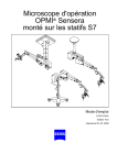
1
OPMI® Sensera
on S7 Suspension Systems
Instructions for use
G-30-1434-en
Issue 10.0
Printed on 30. 01. 2009
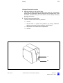
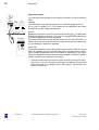
Key to symbols
Different symbols used in this manual draw your attention to safety aspects and useful tips. These symbols are explained in the following.
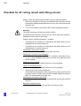
Warning!
The warning triangle indicates potential sources of danger which may
constitute a risk of injury for the user or a health hazard.
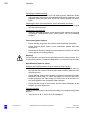
Caution:
The square indicates situations which may lead to malfunction, defects,
collision or damage of the instrument.
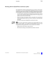
Note:
The hand indicates hints on the use of the instruments or other tips for the
user.
OPMI® is a registered trademark of Carl Zeiss.
Contents
–
Key to symbols
2
Functions at a glance
7
–
OPMI Sensera surgical microscope
8
–
Illumination systems
10
–
S7 floor stand
11
–
S7 ceiling mount with rigid column
12
–
S7 ceiling mount with lifting column
13
Safety
15
–
Notes on installation and use
17
–
Safety devices of the suspension system
22
–
Warning labels and notes
26
Description
31
Sensera surgical microscope on S7 suspension systems
34
–
Intended use
34
–
Description of the system
34
–
System components
36
OPMI Sensera surgical microscope
38
–
Design
38
–
Controls, displays, connections
40
–
Tiltable binocular tube and eyepieces
46
S7 floor stand
50
–
Design
50
–
Controls, displays, connections
52
–
Suspension arm
52
–
Carrier arm, stand column, stand base
54
–
Connector panel of S7 floor stand
56
–
Instrument tray (option)
58
S7 ceiling mount
G-30-1434-en
OPMI® Sensera on S7 Suspension Systems
60
Issue 10.0
Printed on 30. 01. 2009
G-30-1434-en
–
Design
60
–
Controls, displays, connections
62
–
Carrier and suspension arms
62
–
Connector panel of S7 ceiling mount
64
S7 ceiling mount with lifting column
66
–
Design
66
–
Controls, displays, connections
68
–
Ceiling flange with lifting column
68
–
Carrier and suspension arms
70
–
Connector panel of S7 ceiling mount with lifting column
72
Illumination system
74
–
Halogen illumination system
76
–
Xenon illumination system
78
Control panel and menu overview
82
–
Structure of the menus
84
Foot control panel (option)
104
–
Intended use
104
–
Design
104
–
Foot control panel with 14 functions
106
–
Foot control panel with 8 functions
107
Preparations for use
109
Attaching the equipment
112
–
112
Mounting the tube and eyepieces
Connections
114
–
Connecting the strain relief device
114
–
Connecting the suspension system - S7 floor stand
116
– Connecting the suspension system - S7 ceiling mount with
rigid column
118
– Connecting the suspension system - S7 ceiling mount with
lifting column
120
–
122
Connecting video monitor and MediLive ImageBox (option)
Adjusting the system - S7 floor stand
124
–
Balancing the suspension arm
124
–
Setting the limit of downward travel of the suspension arm
124
OPMI® Sensera on S7 Suspension Systems
Issue 10.0
Printed on 30. 01. 2009
G-30-1434-en
Adjusting the system - S7 ceiling mount with rigid column
126
–
Balancing the suspension arm
126
–
Setting the limit of downward travel of the suspension arm
126
Adjusting the system - S7 ceiling mount with lifting column
128
–
Setting an ergonomic working height
128
–
Balancing the suspension arm (ceiling mount with lifting column) 130
–
Setting the limit of downward travel of the suspension arm
130
Balancing the surgical microscope
132
Surgical microscope with a laser micromanipulator
136
Adjusting the surgical microscope
138
Configuring the camera settings (config)
139
Configuring Image Capture
144
Relocating the S7 floor stand
152
Operation
155
Checklist for S7 floor stand
156
Checklist for S7 ceiling mount with rigid column
160
Checklist for S7 ceiling mount with lifting column
164
Procedure
168
–
Working with the SpeedFokus autofocus option
169
–
Display and deletion of images (USB option)
170
What to do in an emergency
172
–
Failure of the focusing function
172
–
Failure of the zoom function
174
–
Failure of the halogen lamp
176
–
Lamp failure of the xenon illumination
178
–
Failure of the SpeedFokus autofocus option
182
Maintenance / Further information
183
–
Trouble-shooting
184
–
Replacing the halogen lamp
190
–
Changing the xenon lamp module
194
–
Magnifications / Fields of view
198
–
Care of the unit
200
–
Cleaning optical surfaces
200
OPMI® Sensera on S7 Suspension Systems
Issue 10.0
Printed on 30. 01. 2009
–
Auxiliaries from Zeiss
201
–
Cleaning mechanical surfaces
201
–
Sterilization
201
–
Disinfecting the control keys
203
–
Ordering data
204
–
Spare parts
207
–
Accessories
209
–
Disposal
210
Technical data
211
–
Technical data
212
–
Integrated 1 CCD PAL video camera (option)
219
–
Integrated 1 CCD NTSC video camera (option)
219
–
Ambient requirements
220
–
Changes to the system
220
Index
G-30-1434-en
OPMI® Sensera on S7 Suspension Systems
221
Issue 10.0
Printed on 30. 01. 2009
7
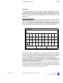
Functions at a glance
Functions at a glance
OPMI Sensera surgical microscope
G-30-1434-en
8
Illumination systems
10
S7 floor stand
11
S7 ceiling mount with rigid column
12
S7 ceiling mount with lifting column
13
OPMI® Sensera on S7 Suspension Systems
Issue 10.0
Printed on 30. 01. 2009
8
Functions at a glance
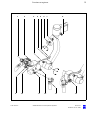
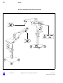
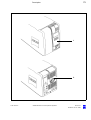
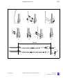
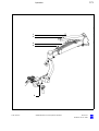
OPMI Sensera surgical microscope
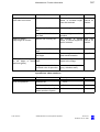
1
2
3
4
5
6
7
8
9
10
11
12
13
14
G-30-1434-en
Adjusting the eyecup and the prescription
Adjusting the interpupillary distance
Manually adjusting the friction of the front-to-back tilt
Motorized adjustment of tilt axis B
(microscope tilts downward)
Motorized adjustment of tilt axis B
(microscope tilts upward)
Manually adjusting the friction of lateral tilt axis A
Manually adjusting the balance of lateral tilt axis A
Manually adjusting the friction of the microscope's
axis of rotation
Locking the handgrip in a convenient position
Manually adjusting zoom (emergency mode)
Manual focusing
Adjusting the spot illumination
Triggering motorized microscope functions
External focus (option)
OPMI® Sensera on S7 Suspension Systems
Pages 36/87
Page 34
Page 84
Page 84
Page 84
Page 82
Page 82
Page 82
Page 32
Pages 30/98
Pages 30/96
Page 30
Page 32
Page 30
Issue 10.0
Printed on 30. 01. 2009
9
Functions at a glance
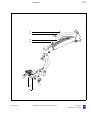
1
2
3
4
5
6
7
8
A
B
9
G-30-1434-en
10
11
12
13
OPMI® Sensera on S7 Suspension Systems
14
Issue 10.0
Printed on 30. 01. 2009
10
Functions at a glance
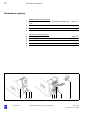
Illumination systems
2
3
4
Halogen illumination system
Closed flap: main lamp is on - Open flap: backup lamp
is on
Selecting a filter
Opening the lamp module
Manual activation of the backup lamp
page 76
page 76
page 76
5
6
7
8
9
Xenon illumination system
Selecting a filter
Resetting the counter
Manual activation of the backup lamp
Opening the lamp module
Red segment is lit - backup lamp is in use
page 78
page 80
page 78
page 78
page 78
1
1
G-30-1434-en
2
3 4
5 6 7
OPMI® Sensera on S7 Suspension Systems
8
page 76
9
Issue 10.0
Printed on 30. 01. 2009
11
Functions at a glance
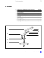
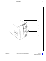
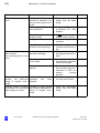
S7 floor stand
9 Lamp housing with halogen or xenon illumination
10 Control panel
11 Maneuvering handle with hooks on which to hang the
foot control panel
12 Connector panel
13 Casters with locking tabs (4 x)
14 Adjusting the friction of the carrier arm's swivel
movement
15 Adjusting the friction of the suspension arm's
swivel movement
16 Balancing the suspension arm
17 Adjusting the limit of downward travel
18 Adjusting the friction of upward/downward movement
9
Page 40
Page 54
Page 88
Page 46
Page 44
Page 44
Page 44
Page 80
Page 80
Page 42
18
17
16
15
10
14
S7
11
12
13
G-30-1434-en
OPMI® Sensera on S7 Suspension Systems
Issue 10.0
Printed on 30. 01. 2009
12
Functions at a glance
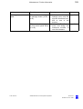
S7 ceiling mount with rigid column
9
10
11
12
13
14
15
16
Control panel
Power switch
Connector panel
Lamp housing with halogen or xenon illumination
Balancing the suspension arm
Adjusting the limit of downward travel
Adjusting the friction of upward/downward movement
Adjusting the friction of the suspension arm's
swivel movement
17 Adjusting the friction of the carrier arm's swivel
movement
16
Page 50
Page 50
Page 44
Page 46
Page 78
Page 78
Page 42
Page 42
Page 42
17
9
10
11
12
13
G-30-1434-en
14
15
OPMI® Sensera on S7 Suspension Systems
Issue 10.0
Printed on 30. 01. 2009
13
Functions at a glance
S7 ceiling mount with lifting column
9
10
11
12
13
14
15
16
17
Control panel
Power switch
Connector panel
Lamp housing with halogen or xenon illumination
Balancing the suspension arm
Adjusting the limit of downward travel
Adjusting the friction of upward/downward movement
Lifting/lowering the lifting column
Adjusting the friction of the carrier arm's swivel
movement
18 Adjusting the friction of the suspension arm's
swivel movement
page 82
page 82
page 72
page 74
page 130
page 130
page 62
page 68
page 62
page 62
18
17
9
10
11
16
12
G-30-1434-en
13
14
15
OPMI® Sensera on S7 Suspension Systems
Issue 10.0
Printed on 30. 01. 2009
14
Functions at a glance
G-30-1434-en
OPMI® Sensera on S7 Suspension Systems
Issue 10.0
Printed on 30. 01. 2009
Safety
15
Notes on installation and use
17
Safety devices of the suspension system
22
Warning labels and notes
26
Safety
G-30-1434-en
OPMI® Sensera on S7 Suspension Systems
Issue 10.0
Printed on 30. 01. 2009
16
Safety
The device described in this manual has been designed and tested in accordance with Carl Zeiss safety standards as well as German and international standards. This guarantees a high degree of instrument safety.
The system described in this user manual has been designed in compliance with the requirements of:
–
EN
–
IEC
–
UL
– CSA
In accordance with Directive 93/42/EEC for medical devices, the complete quality management system of the company Carl Zeiss Surgical
GmbH, 73446 Oberkochen, Germany, has been certified by DQS Deutsche Gesellschaft zur Zertifizierung von Managementsystemen GmbH, a
notified body, under registration number 250758 MP23.
–
As per Directive 93/42/EEC, the unit is a Class I instrument.
–
For USA: FDA classification Class I.
We would like to provide you with information about safety aspects which
must be observed when handling this device. This chapter contains a
summary of the most important information concerning matters relevant
to instrument safety.
Important safety information has been incorporated in this manual and is
marked with a warning triangle accordingly. Please give this information
your special attention.
The correct use of the system is absolutely vital for safe operation. Please
make yourself totally familiar with the contents of this manual prior to startup of the instrument. Please also observe the user manuals of any additional equipment. Further information is available from our service department or from authorized representatives.
G-30-1434-en
•
Please observe all applicable accident prevention regulations.
•
The instrument must be connected to a special emergency backup
line supply in accordance with the regulations or directives which apply in your country.
OPMI® Sensera on S7 Suspension Systems
Issue 10.0
Printed on 30. 01. 2009
17
Safety
Notes on installation and use
Safe working order
•
G-30-1434-en
Do not operate the equipment contained in the delivery package in
–
explosion-risk areas,
–
the presence of inflammable anesthetics or volatile solvents such
as alcohol, benzine or similar chemicals.
•
Do not station or use the instrument in damp rooms. Do not expose
the instrument to water splashes, dripping water or sprayed water.
•
Immediately unplug any equipment that gives off smoke, sparks or
strange noises. Do not use the instrument until our service representative has repaired it.
•
Do not place any fluid-filled containers on top of the instrument. Make
sure that no fluids can seep into the instrument.
•
Do not force cable connections. If the male and female parts do not
readily connect, make sure that they are appropriate for one another.
If any of the connectors are damaged, have our service representative
repair them.
•
Potential equalization: If requested, the instrument can be incorporated into potential equalization measures.
•
Do not use a mobile phone in the vicinity of the equipment because
the radio interference can cause the equipment to malfunction. The effects of radio interference on medical equipment depend on a number
of various factors and are therefore entirely unforeseeable.
•
Modifications and repairs on these instruments or instruments used
with them may only be performed by our service representative or by
other authorized persons.
•
The manufacturer will not accept any liability for damage caused by
unauthorized persons tampering with the instrument; this will also forfeit any rights to claim under warranty.
•
Over longer distances (e.g. removal, return for repair, etc), the instrument may only be transported in the original packaging or in special
return packaging. Please contact your dealer or the Carl Zeiss service
team.
•
Use this instrument only for the applications described.
OPMI® Sensera on S7 Suspension Systems
Issue 10.0
Printed on 30. 01. 2009
18
Safety
•
Only use the instrument with the accessories supplied. Should you
wish to use other accessory equipment, make sure that Carl Zeiss or
the equipment manufacturer has certified that its use will not impair
the safety of instrument.
•
Only personnel who have undergone training and instruction are allowed to use this instrument. It is the responsibility of the customer or
institution operating the equipment to train and instruct all staff using
the equipment.
•
Keep the user's manuals where they are easily accessible at all times
for the persons operating the instrument.
•
Never look at the sun through the binocular tube, the objective lens or
an eyepiece.
•
Do not pull at the light guide cable, at the power cord or at other cable
connections.
•
This instrument is a high-grade technological product. To ensure optimum performance and safe working order of the instrument, its safety
must be checked once every 12 months. We recommend having this
check performed by our service representative as part of regular maintenance work.
If a failure occurs which you cannot correct using the trouble-shooting
table, attach a sign to the instrument stating it is out of order and contact our service representative.
Warning!
Do not use the video images for diagnostic purposes, as the video cameras and the monitor have not been calibrated. The visualized images
may therefore include deviations in shape, contrast and color.
•
Observe the labels showing the symbol "Risk of crushing“!
Notes on EMC (Electromagnetic Compatibility)
The device complies with the EMC requirements of IEC 60601-1-2. For
operating the device, observe the EMC precautions specified below.
Only use spare parts approved by Carl Zeiss for this device.
Do not use any portable or mobile HF communication equipment in the
vicinity of the device, as it cannot be ruled out that the function of the device will be impaired.
G-30-1434-en
OPMI® Sensera on S7 Suspension Systems
Issue 10.0
Printed on 30. 01. 2009
19
Safety
Requirements for operation
•
For ceiling mounts only: Our service staff or a qualified person appointed by us will install the system on ceiling anchors which have
been properly mounted by the construction engineers responsible.
These ceiling anchors must comply with the specifications contained
in our planning manual.
Our service representative or a specialist authorized by us will install the
instrument. Please make sure that the following requirements for operation remain fulfilled in the future:
–
All mechanical connections (details in the user's manual) which are
relevant to safety are properly connected and screw connections tightened.
–
All cables and plugs are in good working condition.
–
The voltage setting on the instrument conforms to the rated voltage of
the line supply on site.
–
The instrument is plugged into a power outlet which has a properly
connected protective ground contact.
–
The power cord being used is the one designed for use with this instrument.
Before every use and after re-equipping the instrument
•
Make sure that all ”Requirements for operation” are fulfilled.
•
Go through the checklist.
•
Re-attach or close any covers, panels or caps which have been removed or opened.
•
Pay special attention to warning symbols on the instrument (triangular
warning signs with exclamation marks), labels and any parts such as
screws or surfaces painted red.
•
Do not cover any ventilation openings.
For every use of the instrument
General
• Never operate the system unattended.
G-30-1434-en
•
Avoid looking directly into the light source, e.g. into the microscope objective lens or a light guide.
•
When the illumination is on, the light guide must be connected at both
ends. Otherwise there is a risk of fire or burn injuries.
OPMI® Sensera on S7 Suspension Systems
Issue 10.0
Printed on 30. 01. 2009
20
Safety
•
Make sure that the instrument has been switched off before you
change the xenon lamp module. When switched on, the ignition system generates high voltage.
•
The xenon illumination system is a high-intensity light source which if used improperly - can cause thermal injury to skin or tissue. Keep
the exposed tissue moist and provide sufficient irrigation. Carefully
monitor the effects of the illumination on the tissue, in particular in the
following cases:
– during prolonged procedures on skin and tissue using objective
lenses with a short focal length (short working distance),
– during procedures on tissue with a low blood supply,
– with high brightness settings of the xenon lamp.
•
Since the xenon lamp provides high light intensity and generates light
with a spectrum similar to daylight, it must not be used for ophthalmic
applications.
•
Any kind of radiation has a detrimental effect on biological tissue.This
also applies to the light illuminating the surgical field. Please therefore
reduce the brightness and duration of illumination on the surgical field
to the absolute minimum required.
S7 floor stand
• Using the brake tabs on the base, secure the stand in position. Make
sure that the stand is stable and cannot roll away.
S7 ceiling mount with lifting column
• The lifting column is used to move the microscope into position for surgery prior to the surgical procedure.
Do not constantly move the lifting column up and down, since a thermal cut-out will then automatically switch off the drive motor. If this occurs, the lifting column cannot be moved again until the motor has
cooled down.
After every use of the instrument
G-30-1434-en
•
Always use the main power switch of the instrument to turn it off.
•
The main power switch must always be turned off when the instrument
is not in use.
OPMI® Sensera on S7 Suspension Systems
Issue 10.0
Printed on 30. 01. 2009
21
Safety
G-30-1434-en
OPMI® Sensera on S7 Suspension Systems
Issue 10.0
Printed on 30. 01. 2009
22
Safety
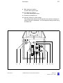
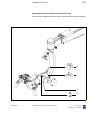
Safety devices of the suspension system
Lifting column
1
2
Selector switch
for setting the optimum viewing height of the surgical microscope or for
downward movement into the working position.
As long as you keep the selector switch in the turned position, the lifting
column moves upward (2) or downward (1), depending on the switch position. When you release the selector switch, the lifting column stops immediately.
The switching technology causes a delay of approx. 2 seconds at the
upper and lower end positions of the lifting column. After this time, you
can move the column in the opposite direction again by activating the selector switch.
–
Before raising or lowering the suspension system, make sure that
there is sufficient clearance from other objects so that any collision is
avoided.
Warning!
– Do not activate the lifting column during surgery!
G-30-1434-en
–
Do not use the lifting column for focusing.
–
Make sure that the patient is not put at risk or injured by the motorized
adjustment of the lifting column.
OPMI® Sensera on S7 Suspension Systems
Issue 10.0
Printed on 30. 01. 2009
23
Safety
Halogen illumination system
1
Manual switching to the backup lamp
The lamp housing contains a backup lamp which is automatically
swung into the illumination beam path when the first lamp fails. If this
automatic function fails, you can switch on the backup lamp by
pressing this button.
2
GG 475 retina protection filter
The filter selector knob has four positions:
0
no filter
1
GG 475 filter: to protect the patient's eye during treatment
against unnecessary (blue) radiation (retinal injury).
2
KK 40 filter: to increase color temperature
3
no filter
1
2
G-30-1434-en
OPMI® Sensera on S7 Suspension Systems
Issue 10.0
Printed on 30. 01. 2009
24
Safety
Xenon illumination system
Warning!
The xenon lamp has a limited service life of 500 h.
If used beyond its maximum service life, the xenon lamp may explode.
Change the xenon lamp in good time.
Warning!
Lamp rupture (audible as a loud bang) may lead to jamming of the lamp
module and/or failure of the electronics modules.
•
Before opening the lamp housing, make sure that the system is moved
to a position where neither the patient nor the user is put at risk by falling items.
•
Do not continue using the system if the lamp module is jammed or the
illumination is no longer operational due to defective electronics modules. Inform our service department.
1
Switching to the backup lamp
The lamp module contains two xenon lamps. The second lamp is used
as a backup lamp which has to be swung into the illumination beam
path when the first lamp fails.
If the xenon lamp fails, open the lamp module as follows:
Press button (3). The lamp module is slightly ejected. Pull out the lamp
module as far as it will go. Turn knob (1) through 180° until it snaps in.
This moves the backup lamp into the illumination beam path. Push the
lamp module all the way back into the lamp housing.
2
Indicator: backup lamp is in use
When the red segment in knob (1) lights up, the backup lamp is in use.
Note:
If the first lamp has failed and the backup lamp is in use, make sure to
have a backup lamp module ready at hand as a precaution.
G-30-1434-en
OPMI® Sensera on S7 Suspension Systems
Issue 10.0
Printed on 30. 01. 2009
25
Safety
1
3
2
2
G-30-1434-en
OPMI® Sensera on S7 Suspension Systems
Issue 10.0
Printed on 30. 01. 2009
26
Safety
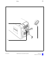
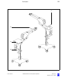
Warning labels and notes
Caution:
Observe all warning labels and notes!
If any label is missing on your instrument or has become illegible, please
contact us or one of our authorized representatives. We will supply the
missing labels.
2
1
OPMI® Sensera
000000-0000-000
G-30-1434-en
OPMI® Sensera on S7 Suspension Systems
Issue 10.0
Printed on 30. 01. 2009
27
Safety
14
176164
- Balance +
G-30-1434-en
OPMI® Sensera on S7 Suspension Systems
Issue 10.0
Printed on 30. 01. 2009
28
Safety
S7 floor stand with instrument tray option
G-30-1434-en
OPMI® Sensera on S7 Suspension Systems
Issue 10.0
Printed on 30. 01. 2009
29
Safety
14
- Balance +
176164
G-30-1434-en
OPMI® Sensera on S7 Suspension Systems
Issue 10.0
Printed on 30. 01. 2009
30
Safety
14
- Balance +
176164
G-30-1434-en
OPMI® Sensera on S7 Suspension Systems
Issue 10.0
Printed on 30. 01. 2009
Description
31
Sensera surgical microscope on S7 suspension systems
34
Intended use
34
Description of the system
34
System components
36
OPMI Sensera surgical microscope
38
Design
38
Controls, displays, connections
40
Tiltable binocular tube and eyepieces
46
S7 floor stand
50
Design
50
Controls, displays, connections
52
Suspension arm
52
Carrier arm, stand column, stand base
54
Connector panel of S7 floor stand
56
Instrument tray (option)
58
S7 ceiling mount
60
Design
60
Controls, displays, connections
62
Carrier and suspension arms
62
Connector panel of S7 ceiling mount
64
S7 ceiling mount with lifting column
66
Design
66
Controls, displays, connections
68
Ceiling flange with lifting column
68
Carrier and suspension arms
70
Connector panel of S7 ceiling mount with lifting column
72
Description
G-30-1434-en
OPMI® Sensera on S7 Suspension Systems
Issue 10.0
Printed on 30. 01. 2009
32
Description
G-30-1434-en
Illumination system
74
Halogen illumination system
76
Xenon illumination system
78
Control panel and menu overview
82
Structure of the menus
84
Foot control panel (option)
104
Intended use
104
Design
104
Foot control panel with 14 functions
106
Foot control panel with 8 functions
107
OPMI® Sensera on S7 Suspension Systems
Issue 10.0
Printed on 30. 01. 2009
33
Description
G-30-1434-en
OPMI® Sensera on S7 Suspension Systems
Issue 10.0
Printed on 30. 01. 2009
34
Description
Sensera surgical microscope on S7 suspension systems
Intended use
The OPMI Sensera surgical microscope on S7 suspension systems has
been specially designed for use in ENT surgery, i.e. the overall system
meets the special requirements of this discipline.
The system is intended for use in hospitals, clinics or other human medicine institutions.
The system must only be operated by physicians, nurses and other OR
staff who have undergone appropriate training and observe the instructions of the user's manual. The installation conditions and the use of the
system must meet microsurgical requirements:
–
low vibration
–
clean environment
–
avoidance of extreme mechanical stress.
Description of the system
The apochromatic optics of the microscope provide superb optical quality.
The microscope image displays optimum contrast and excellent detail
recognition along with outstanding depth of field and maximum 3D perception. The 1:6 ratio zoom system allows the magnification of the overall
system to be set as required by the surgical procedure.
You can use the surgical microscope with or without an integrated video
camera. Depending on your requirements, you can choose between a
PAL or an NTSC video system.
Suspension systems
The S7 floor stand is a suspension system for Zeiss surgical microscopes. It comprises a suspension arm, a carrier arm, a stand column and
a stand base.
A maneuvering handle attached to the stand column is used to move the
stand and to attach the foot control panel. The stand column is provided
on its left and right with cable supports for winding up cables before the
unit is relocated.
G-30-1434-en
OPMI® Sensera on S7 Suspension Systems
Issue 10.0
Printed on 30. 01. 2009
35
Description
The stand base is extremely easy to move on its four casters. It has been
designed in such a way that high stability is ensured even with unfavorable loading of the stand. The locking tabs permit you to reliably secure
the floor stand in position at the site of use.
Note:
As the stand is very easy to maneuver, there is a tendency to underestimate its weight. Therefore, move the stand slowly and carefully!
The S7 ceiling mount with rigid column is a suspension system for
Zeiss surgical microscopes. It comprises a suspension arm, a carrier arm,
a ceiling column and a ceiling flange.
The S7 ceiling mount with lifting column is a suspension system for
Zeiss surgical microscopes. It comprises a suspension arm, a carrier arm,
a ceiling flange and a lifting column. This motorized lifting column permits
the viewing height to be perfectly matched to the surgeon's requirements.
The carrier arm of all suspension systems contains the control unit with all
electrical supply systems required for the control of a motorized surgical
microscope. You can control the motorized functions using the handgrips,
or via a foot control panel (option). A light guide (fiber optic illumination)
directs the light from the lamp housing in the suspension system to the
surgical microscope.
The suspension arm of all types of suspension system permits almost effortless positioning of the surgical microscope. The spring force of the
suspension arm can be varied in a range from 6 to 14 kg, permitting reliable balancing of the microscope even with accessory equipment attached. The downward movement of the suspension arm can be limited
using an adjustable positioning aid.
A control panel allows the adjustment of user-defined settings such as the
zoom, focus, brightness and video settings, and the programming of the
configurable handgrip buttons.
The SpeedFokus autofocus option permits you to select features (ROI, region of interest) in the image of the surgical field and to rapidly focus on
them automatically or at the press of a button.
USB memory option
An optional USB port permits you to save image data in the JPEG or TIFF
format on a USB memory stick. Image data can also be read from a USB
memory stick and displayed on a connected monitor. The saved image
data can also be deleted.
Warning!
If the xenon light source is used, the unit must not be used in ophthalmic
applications. Severe injury to the patient's eye is possible.
G-30-1434-en
OPMI® Sensera on S7 Suspension Systems
Issue 10.0
Printed on 30. 01. 2009
36
Description
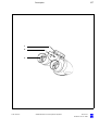
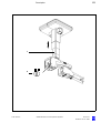
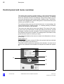
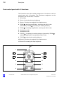
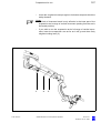
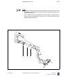
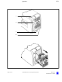
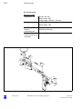
System components
1
S7 ceiling mount with lifting column
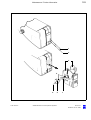
2
S7 ceiling mount
3
S7 floor stand
4
OPMI Sensera surgical microscope
with 180° tiltable tube and magnetic eyepieces
Note:
The overall system comprises a suspension system and a microscope. All options described in this user manual can be ordered separately.
G-30-1434-en
OPMI® Sensera on S7 Suspension Systems
Issue 10.0
Printed on 30. 01. 2009
37
Description
1
2
3
4
G-30-1434-en
OPMI® Sensera on S7 Suspension Systems
Issue 10.0
Printed on 30. 01. 2009
38
Description
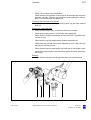
OPMI Sensera surgical microscope
Design
The Sensera surgical microscope comprises the following modules:
1
Microscope body
The apochromatic optics of the microscope provide superb optical
quality. The microscope image displays optimum contrast and excellent detail recognition along with outstanding depth of field and maximum 3D perception. The 1:6 ratio zoom system allows the magnification of the overall system to be set as required by the surgical
procedure. Using the integrated variable focusing optics (Varioskop),
you can adjust the working distance between 200 mm and 415 mm as
required.
2
Support arm for the surgical microscope
3
Balancing system
This system allows almost effortless balancing of the surgical microscope.
4
Axis of microscope rotation
5
Coupling
for mounting the surgical microscope on the suspension system.
6
Handgrips
for moving the surgical microscope. Using the buttons on the handgrips, you can control important functions (e.g. focusing, zooming,
brightness, still/video camera release).
Warning!
To permit almost effortless guidance of the surgical microscope, the microscope and the suspension system used must be correctly balanced.
If the system is in an extremely unbalanced state, the unit can move uncontrollably out of position. For this reason, hold the surgical microscope
tightly at its handgrips before loosening the friction adjustment screw (see
page 52) on the suspension arm.
7
G-30-1434-en
Motorized fine focusing (option),
recommended for the use of OPMI Sensera with laser micromanipulators.
OPMI® Sensera on S7 Suspension Systems
Issue 10.0
Printed on 30. 01. 2009
39
Description
1
2
3
4
5
7
2
6
G-30-1434-en
OPMI® Sensera on S7 Suspension Systems
Issue 10.0
Printed on 30. 01. 2009
40
Description
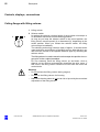
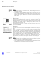
Controls, displays, connections
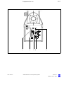
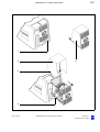
2
1
Friction adjustment for vertical axis
Use this knob to adjust the friction for the vertical axis as required.
2
Balance setting of the lateral tilt motion
Use this knob to adjust the balance setting of the lateral tilt motion.
3
Adjusting the friction of the lateral tilt axis
Use this knob to adjust the friction for the lateral tilt axis as required.
4
Balance setting of the front-to-back tilt motion
When you press this button, the microscope slowly tilts upward.
5
Balance setting of the front-to-back tilt motion
When you press this button, the microscope slowly tilts downward.
6
Adjusting the friction of the front-to-back tilt axis
Use this knob to adjust the friction for the front-to-back tilt axis as required.
7
Marking for zero position
In the zero position, the microscope body is decoupled from the suspension (see "Balancing the front-to-back tilt motion").
1
Zero position
G-30-1434-en
OPMI® Sensera on S7 Suspension Systems
Issue 10.0
Printed on 30. 01. 2009
41
Description
1
2
3
4
2
1
5
2
6
1
7
G-30-1434-en
OPMI® Sensera on S7 Suspension Systems
Issue 10.0
Printed on 30. 01. 2009
42
Description
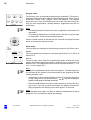
8
Dust cover
9
Handgrips (removable)
for moving the surgical microscope and triggering the motorized OPMI
functions (see points 14 to 17).
10 Locking screw
for optimum positioning of the handgrips.
11 Zoom wheel (emergency operation)
If the motorized functions fail, you can manually adjust the magnification after removing the plastic cover from the zoom wheel.
12 Focusing knob
for manual adjustment of the image definition (focus, working distance).
13 Spot illumination knob
for continuous adjustment of the illuminated field diameter.
14 Focusing knob for use of a laser micromanipulator (option)
for manual adjustment of the image definition (focus) when a laser micromanipulator is used.
G-30-1434-en
OPMI® Sensera on S7 Suspension Systems
Issue 10.0
Printed on 30. 01. 2009
43
Description
8
9
10
11
12
13
14
G-30-1434-en
OPMI® Sensera on S7 Suspension Systems
Issue 10.0
Printed on 30. 01. 2009
44
Description
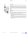
15 Release buttons, freely programmable
In combination with an S7 suspension system, specific functions of the
suspension system can be assigned to these buttons (e. g.: focus,
zoom, brightness control, still and video camera release, etc.). Configuring these buttons is described on page 91 (Handgrip Settings
menu).
The default setting is brightness control.
Z
16 Zoom rocker switch
for adjusting the magnification factor γ from 0.4x to 2.4x.
F
17 Focus rocker switch
for continuous focusing within the working distance of 200 to 415 mm.
Note: The maximum value achievable can only be set manually.
18 Release buttons, freely programmable
In combination with an S7 suspension system, specific functions of the
suspension system can be assigned to these buttons (e. g.: focus,
zoom, brightness control, still and video camera release, etc.). Configuring these buttons is described in chapter "Description/Structure of
the menus".
19 Locking the handgrips in position
Using this locking device, you can lock each handgrip in different positions.
20 Knurled nut
for removing the handgrips.
21 Knobs instead of handgrips
After removing the handgrips, mount the knobs supplied to protect the
connector contacts and to be able to guide the surgical microscope.
These knobs can be provided with sterile caps.
22 Labeling fields
Labeling fields are provided for the freely programmable handgrip buttons. On delivery, you receive a labeling set (small stickers) for each
handgrip, permitting you to label the handgrips in accordance with
your specific button assignment.
The labeling set includes not only stickers with abbreviations for the
functions provided, but also with the letters A, B, C and D.
If several users with different button configurations are working on the
system, operating errors can be avoided by labeling the freely programmable buttons with A, B, C, D or E instead of specific functions,
i.e. by using the same designations for the buttons as in the description of the menus, see from page 91.
G-30-1434-en
OPMI® Sensera on S7 Suspension Systems
Issue 10.0
Printed on 30. 01. 2009
45
Description
15
16
17
F
Z
18
19
20
21
F
G-30-1434-en
Z
22
OPMI® Sensera on S7 Suspension Systems
Issue 10.0
Printed on 30. 01. 2009
46
Description
Tiltable binocular tube and eyepieces
180° tiltable tube
G-30-1434-en
1
PD adjustment knob
The correct position has been set when the two eyepiece images
merge into one.
2
180° tiltable tube
3
Eyepiece tube
OPMI® Sensera on S7 Suspension Systems
Issue 10.0
Printed on 30. 01. 2009
47
Description
1
2
3
G-30-1434-en
OPMI® Sensera on S7 Suspension Systems
Issue 10.0
Printed on 30. 01. 2009
48
Description
Widefield eyepieces with magnetic coupling
Note:
When you remove these eyepieces from the tube, please note that they
are fitted with a magnetic coupling. When mounted, the eyepieces display
a very weak magnetic field, so that the usual rules for the handling of magnets must only be observed with eyepieces which have not been mounted
on the microscope:
G-30-1434-en
•
Do not place the eyepieces close to instruments where there is any
risk of magnetization.
•
Do not place the eyepieces on sensitive electronic units such as infusion pumps, cardiac pace-makers, measuring instruments or magnetic data carriers such as disks, audiotapes and videotapes, or credit
cards.
•
Always store eyepieces not used in their original packaging.
1
Eyecup
Always adjust the eyecups in such a way that you can see the full field
of view.
–
Viewing with eyeglasses:
Screw in the eyecups all the way.
–
Viewing without eyeglasses: Screw out the eyecups until you
see the full field of view.
2
Diopter adjustment ring
The eyepieces provide ametropia compensation between -8 D and
+5 D. Eyeglass wearers who perform surgery wearing their glasses
set the diopter adjustment ring to 0 D. Turn the ring until you have obtained the optimum setting. An integrated brake holds the ring in the
position set.
3
Diopter scale
for reading the prescription set.
OPMI® Sensera on S7 Suspension Systems
Issue 10.0
Printed on 30. 01. 2009
49
Description
1
2
3
G-30-1434-en
OPMI® Sensera on S7 Suspension Systems
Issue 10.0
Printed on 30. 01. 2009
50
Description
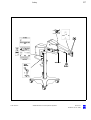
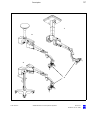
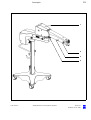
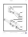
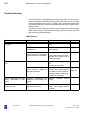
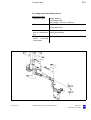
S7 floor stand
Design
G-30-1434-en
1
Suspension arm
2
Lamp housing (either xenon or halogen illumination)
3
Carrier arm
4
Control panel
5
Connector panel
6
Maneuvering handle
7
Cable supports (2x, on the right and left of the stand column)
8
Stand column
9
Stand base
OPMI® Sensera on S7 Suspension Systems
Issue 10.0
Printed on 30. 01. 2009
51
Description
1
2
3
4
S7
5
6
7
8
9
G-30-1434-en
OPMI® Sensera on S7 Suspension Systems
Issue 10.0
Printed on 30. 01. 2009
52
Description
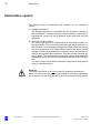
Controls, displays, connections
Suspension arm
- Balance +
G-30-1434-en
1
Lamp housing with halogen or xenon illumination
The suspension system is equipped with an illumination system for
light guides. Each lamp housing contains a backup lamp. When a halogen illumination system is used, the backup lamp will be automatically swung in if the first lamp fails. When a xenon illumination system is
used, you must manually swing the backup lamp into the beam path if
the first lamp fails.
2
Friction adjustment
Knob for adjusting the friction of the suspension arm's upward/downward movement.
3
Locking lever for limiting the arm's downward movement
You can limit the downward movement of the suspension arm by adjusting a stop.
Adjustment range: from the horizontal position of the suspension arm
to its lower stop.
4
Balance setting
Knob for setting the spring force for balancing. After mounting the surgical microscope including all accessories, balance the suspension
arm using this screw. The balance setting procedure is described in
the chapter “Preparations for use/Adjusting the system“.
OPMI® Sensera on S7 Suspension Systems
Issue 10.0
Printed on 30. 01. 2009
53
Description
1
2
3
4
G-30-1434-en
OPMI® Sensera on S7 Suspension Systems
Issue 10.0
Printed on 30. 01. 2009
54
Description
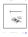
Carrier arm, stand column, stand base
G-30-1434-en
1
Control and display panel
The control and display panel permits you to control all electrical functions of the S7 floor stand and the surgical microscope.
2
Friction adjustment
Knob for adjusting the friction of the carrier arm's swivel movement.
3
Handle
for moving the floor stand. Before relocating the stand, you can hang
the foot control panel and wind up the cables on the lower end of the
handle.
4
Connector panel
for connecting the unit to line power. Further connectors are provided
for powering peripheral equipment. A foot control panel can be connected to a multi-point connector.
5
Friction adjustment
Knob for adjusting the friction of the suspension arm's swivel movement.
6
Cable support
for winding up the power cord and the cable of the foot control panel.
7
Support for foot control panel
8
Locking tab
for steerable caster (4 casters are provided).
To secure the stand in position, press down at least two locking tabs.
Press down to lock the caster.
Press up to release the caster.
9
Steerable caster
The four casters roll very smoothly, permitting the unit to be easily
wheeled to the site of use.
OPMI® Sensera on S7 Suspension Systems
Issue 10.0
Printed on 30. 01. 2009
55
Description
1
2
3
4
5
6
7
8
9
G-30-1434-en
OPMI® Sensera on S7 Suspension Systems
Issue 10.0
Printed on 30. 01. 2009
56
Description
Connector panel of S7 floor stand
1
Opening for the system cable of an external video camera
2
Remote control socket
for controlling MediLive ImageBox, MediLive MindStream or other external devices with a maximum breaking capacity of 24V/0.5A.
3
Strain relief device
The strain relief device prevents inadvertent unplugging of the following electrical connections:
– power cable,
– video connection cable,
cable for the foot control panel (option).
4
Connector for control component (option)
Here, a foot control panel can be connected.
Warning!
Please observe the maximum current consumption of power outlet
socket (5). Only connect medical devices approved by Carl Zeiss to
this outlet. When using other instruments, make sure that safety is
guaranteed regarding admissible ground leakage currents. The admissible limit value of the ground leakage current present in the suspension system's power cord must not exceed 500 µA in compliance
with EN 60601-1/IEC 60601-1. CSA/US certification in compliance
with UL 60601-1 only allows a maximum ground leakage current of
300 µA.
5
Power outlet socket
for medical devices with a maximum current consumption of 5 A.
Warning!
The current of this power outlet socket cannot be switched off with the
power switch.
6
Power inlet socket
Connectors for USB option
G-30-1434-en
7
USB socket for USB memory stick
Note:
Only use sticks conforming to the USB-2.0 specification.
8
DV output port (FireWire)
Digital, compressed video signal for recording on a digital video recorder or PC.
OPMI® Sensera on S7 Suspension Systems
Issue 10.0
Printed on 30. 01. 2009
57
Description
9
BNC video port (option)
for VBS video signal output
10 Y/C video port (option)
for S-VHS video signal output
11 Potential equalization pin
12 Indicator window for rated voltage
The voltage shown here must correspond to the rated line voltage provided on the site of installation. You can adjust the sliding switch using
a suitable tool.
1
G-30-1434-en
2
3
4
5
6
7, 8
OPMI® Sensera on S7 Suspension Systems
9
10
11 12
Issue 10.0
Printed on 30. 01. 2009
58
Description
Instrument tray (option)
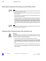
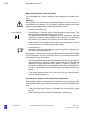
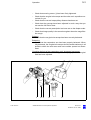
The S7 floor stand can be equipped or retrofitted with an instrument tray
(1). In the case of retrofitting, our service staff or an authorized person will
mount the instrument tray on your stand.
The maximum load on instrument tray (1) must not exceed 13 kg! The tray
has been designed, for example, for mounting MediLive Trio from Zeiss:
–
MediLive Trio is secured on the instrument tray using two stud bolts.
–
A second MediLive Trio or other accessory equipment can be mounted on the instrument tray using the strap provided. Please note the instrument tray's maximum load capacity of 13 kg.
Warning!
• Make sure that the accessory equipment is positioned as securely as
possible on the instrument tray.
G-30-1434-en
•
Mount MediLive Trio on the instrument tray using the two stud bolts.
•
If required, secure further accessory equipment on the tray using the
strap provided.
•
Do not place a load of more than 13 kg on instrument tray (1).
•
Remember there is a risk of collision and crushing when suspension
arm (2) is folded to its moving position. A "Risk of crushing" warning
label is therefore attached on the left and right of suspension arm (2).
•
Please read the relevant user manual before starting up the accessory
equipment.
•
Never pull or push at the accessory equipment (3) in order to move the
S7 floor stand. Always use only maneuvering handle (4) to move the
S7 floor stand.
OPMI® Sensera on S7 Suspension Systems
Issue 10.0
Printed on 30. 01. 2009
59
Description
1
2
3
4
G-30-1434-en
OPMI® Sensera on S7 Suspension Systems
Issue 10.0
Printed on 30. 01. 2009
60
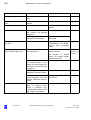
Description
S7 ceiling mount
Design
G-30-1434-en
1
Ceiling flange
2
Ceiling column
3
Control panel
4
Connector panel
5
Lamp housing (either xenon or halogen illumination)
6
Carrier arm
7
Suspension arm
OPMI® Sensera on S7 Suspension Systems
Issue 10.0
Printed on 30. 01. 2009
61
Description
1
2
7
3
6
4
5
G-30-1434-en
OPMI® Sensera on S7 Suspension Systems
Issue 10.0
Printed on 30. 01. 2009
62
Description
Controls, displays, connections
Carrier and suspension arms
- Balance +
G-30-1434-en
1
Lamp housing with halogen or xenon illumination
The suspension system is equipped with an illumination system for
light guides. Each lamp housing contains a backup lamp. When a halogen illumination system is used, the backup lamp will be automatically swung in if the first lamp fails. When a xenon illumination system is
used, you must manually swing the backup lamp into the beam path if
the first lamp fails.
2
Friction adjustment
Knob for adjusting the friction of the suspension arm's upward/downward movement.
3
Locking lever for limiting the arm's downward movement
You can limit the downward movement of the suspension arm by adjusting a stop.
Adjustment range: from the horizontal position of the suspension arm
to its lower stop.
4
Balance setting
Knob for setting the spring force for balancing. After mounting the surgical microscope including all accessories, balance the suspension
arm using this screw. The balance setting procedure is described in
the chapter "Preparations for use“ under "Adjusting the system“.
5
Friction adjustment
Knob for adjusting the friction of the suspension arm's swivel movement.
6
Friction adjustment
Knob for adjusting the friction of the carrier arm's swivel movement.
7
Control and display panel
The control and display panel permits you to control all electrical functions of the S7 suspension system and the surgical microscope.
8
Connector panel
Further connectors are provided for powering peripheral equipment. A
foot control panel (option) can be connected to a multi-point connector.
OPMI® Sensera on S7 Suspension Systems
Issue 10.0
Printed on 30. 01. 2009
63
Description
1
2
3
4
5
6
7
8
G-30-1434-en
OPMI® Sensera on S7 Suspension Systems
Issue 10.0
Printed on 30. 01. 2009
64
Description
Connector panel of S7 ceiling mount
1
Opening for the system cable of an external video camera
2
Remote control socket
for controlling MediLive ImageBox, MediLive MindStream or other external devices with a maximum breaking capacity of 24V/0.5A.
3
Strain relief device
The strain relief device prevents inadvertent unplugging of the following electrical connections:
– video connection cable
– cable for the foot control panel (option).
4
Connector for control component (option)
Here, a foot control panel can be connected.
Connectors for USB option
G-30-1434-en
5
USB socket for USB memory stick
Note:
Only use sticks conforming to the USB-2.0 specification.
6
DV output port (FireWire)
Digital, compressed video signal for recording on a digital video recorder or PC.
7
BNC video port (option)
for VBS video signal output.
8
Y/C video port (option)
for S-VHS video signal output.
9
Indicator window for rated voltage
The voltage shown here must correspond to the rated line voltage provided on the site of installation. You can adjust the sliding switch using
a suitable tool.
OPMI® Sensera on S7 Suspension Systems
Issue 10.0
Printed on 30. 01. 2009
65
Description
1
G-30-1434-en
2
3
4
OPMI® Sensera on S7 Suspension Systems
5, 6
7
8
9
Issue 10.0
Printed on 30. 01. 2009
66
Description
S7 ceiling mount with lifting column
Design
G-30-1434-en
1
Ceiling flange
2
Lifting column
3
Control panel
4
Connector panel
5
Lamp housing (either xenon or halogen illumination)
6
Suspension arm
7
Carrier arm
OPMI® Sensera on S7 Suspension Systems
Issue 10.0
Printed on 30. 01. 2009
67
Description
1
2
7
3
6
4
5
G-30-1434-en
OPMI® Sensera on S7 Suspension Systems
Issue 10.0
Printed on 30. 01. 2009
68
Description
Controls, displays, connections
Ceiling flange with lifting column
3
1
Lifting column
2
Selector switch
for setting the optimum viewing height of the surgical microscope or
for downward movement into the working position.
As long as you keep the selector switch in the turned position, the
lifting column moves upward (4) or downward (3), depending on the
switch position. When you release the selector switch, the lifting
column stops immediately.
The switching technology causes a delay of approx. 2 seconds at the
upper and lower end positions of the lifting column. After this time, you
can move the column in the opposite direction again by activating the
selector switch.
4
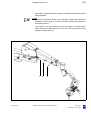
The lifting column is used to move the microscope into position for surgery prior to the surgical procedure.
Do not constantly move the lifting column up and down, since a
thermal cut-out will then automatically deactivate the drive motor. If
this occurs, the lifting column cannot be moved until the motor has
cooled down.
Warning!
– Do not activate the lifting column during surgery!
G-30-1434-en
–
Do not use the lifting column for focusing.
–
Make sure that the patient is not put at risk or injured by the motorized
adjustment of the lifting column.
OPMI® Sensera on S7 Suspension Systems
Issue 10.0
Printed on 30. 01. 2009
69
Description
1
2
G-30-1434-en
OPMI® Sensera on S7 Suspension Systems
Issue 10.0
Printed on 30. 01. 2009
70
Description
Carrier and suspension arms
- Balance +
G-30-1434-en
1
Lamp housing with halogen or xenon illumination
The suspension system is equipped with an illumination system for
light guides. Each lamp housing contains a backup lamp. When a halogen illumination system is used, the backup lamp will be automatically swung in if the first lamp fails. When a xenon illumination system is
used, you must manually swing the backup lamp into the beam path if
the first lamp fails.
2
Friction adjustment
Knob for adjusting the friction of the suspension arm's upward/downward movement.
3
Locking lever for limiting the arm's downward movement
You can limit the downward movement of the suspension arm by adjusting a stop.
Adjustment range: from the horizontal position of the suspension arm
to its lower stop.
4
Balance setting
Knob for setting the spring force for balancing. After mounting the surgical microscope including all accessories, balance the suspension
arm using this screw. The balance setting procedure is described in
the chapter “Preparations for use/Adjusting the system“.
5
Friction adjustment
Knob for adjusting the friction of the suspension arm's swivel movement.
6
Friction adjustment
Knob for adjusting the friction of the carrier arm's swivel movement.
7
Control and display panel
The control and display panel permits you to control all electrical functions of the S7 suspension system and the surgical microscope.
8
Connector panel
Further connectors are provided for powering peripheral equipment. A
foot control panel (option) can be connected to a multi-point connector.
OPMI® Sensera on S7 Suspension Systems
Issue 10.0
Printed on 30. 01. 2009
71
Description
1
2
3
4
5
6
7
8
G-30-1434-en
OPMI® Sensera on S7 Suspension Systems
Issue 10.0
Printed on 30. 01. 2009
72
Description
Connector panel of S7 ceiling mount with lifting column
1
Opening for the system cable of an external video camera
2
Remote control socket
for controlling MediLive ImageBox, MediLive MindStream or other external devices with a maximum breaking capacity of 24V/0.5A.
3
Strain relief device
The strain relief device prevents inadvertent unplugging of the following electrical connections:
– video connection cable
– cable for the foot control panel (option).
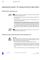
2
4
Selector switch
for setting the optimum viewing height of the surgical microscope or
for upward movement into the standby position.
As long as you keep the selector switch in the turned position, the
lifting column moves upward (1) or downward (2), depending on the
switch position. When you release the selector switch, the lifting
column stops immediately.
The switching technology causes a delay of approx. 2 seconds at the
upper and lower end positions of the lifting column. After this time, you
can move the column in the opposite direction again by activating the
selector switch.
5
Connector for control component (option)
Here, a foot control panel can be connected.
1
Connectors for USB option
G-30-1434-en
6
USB socket for USB memory stick
Note:
Only use sticks conforming to the USB-2.0 specification.
7
DV output port (FireWire)
Digital, compressed video signal for recording on a digital video recorder or PC.
8
BNC video port (option)
for VBS video signal output
9
Y/C video port (option)
for S-VHS video signal output
OPMI® Sensera on S7 Suspension Systems
Issue 10.0
Printed on 30. 01. 2009
73
Description
10 Indicator window for rated voltage
The voltage shown here must correspond to the rated line voltage provided on the site of installation. You can adjust the sliding switch using
a suitable tool.
1
G-30-1434-en
2 3
4
5
OPMI® Sensera on S7 Suspension Systems
6, 7
8
9
10
Issue 10.0
Printed on 30. 01. 2009
74
Description
Illumination system
Two different types of illumination are available for the suspension
system.
1
Halogen illumination
The halogen light source is equipped with an illumination system for
fiber illumination. The lamp housing contains a backup lamp which is
automatically swung into the illumination beam path when the first
lamp fails.
2
Xenon illumination system
The xenon light source is equipped with an illumination system for
fiber illumination. The xenon lamp generates light whose spectrum resembles that of natural daylight. Regardless of the brightness setting,
the color temperature of the light always remains the same. Normal
daylight film without any additional conversion filters can therefore be
used for photographic documentation. The lamp module contains two
xenon lamps. The second lamp is used as a backup lamp which can
be manually swung into the illumination beam path when the first lamp
fails.
You have to pull out the lamp module all the way before being able to
swing in the backup lamp.
Warning!
The xenon illumination must not be used for ophthalmic procedures.
Make sure that no xenon light enters the patient's eyes during paranasal
sinus surgery. Use the spot illumination and cover the eyes of the patient.
G-30-1434-en
OPMI® Sensera on S7 Suspension Systems
Issue 10.0
Printed on 30. 01. 2009
75
Description
1
2
G-30-1434-en
OPMI® Sensera on S7 Suspension Systems
Issue 10.0
Printed on 30. 01. 2009
76
Description
Halogen illumination system
The illumination system has been designed for fiber illumination. The
lamp housing contains a backup lamp which is automatically swung into
the illumination beam path when the first lamp fails.
1
Lamp module
2
Caution:
Do not cover the ventilation grid! For example, drapes could be covering the grid. This can lead to overheating of the lamp modules and
to lamp failure.
3
Flap
The flap is the mechanical indicator for the operating status of the halogen lamps.
– When the flap is closed, the main lamp is operative.
– When the flap is open, the main lamp has failed. The backup lamp
is on.
G-30-1434-en
4
Manual selection of the backup lamp
If the automatic selector system fails, press this button to switch on the
backup lamp.
5
Opening the lamp module
When you press this button, the lamp module is slightly ejected. Pull
out the lamp module all the way for lamp change.
6
Filter selector knob
The filter selector knob has four positions:
0
no filter
1
GG 475 filter: to protect the patient's eye during surgery against
unnecessary (blue) radiation (retinal injury).
2
KK 40 filter: to increase the color temperature
3
no filter
OPMI® Sensera on S7 Suspension Systems
Issue 10.0
Printed on 30. 01. 2009
77
Description
1
2
3
4
5
6
G-30-1434-en
OPMI® Sensera on S7 Suspension Systems
Issue 10.0
Printed on 30. 01. 2009
78
Description
Xenon illumination system
Warning!
The xenon lamp has a limited service life of 500 h.
If used beyond its maximum service life, the xenon lamp may explode.
Change the xenon lamp in good time.
The xenon illumination system has been designed for fiber illumination.
The xenon lamp generates light whose spectrum resembles that of natural daylight. Regardless of the brightness setting, the color temperature
of the light always remains the same. Normal daylight film without any additional conversion filters can therefore be used for photographic documentation. The lamp housing contains two xenon lamps. The second
lamp is used as a backup lamp which must be swung into the illumination
beam path should the first lamp fail.
Warning!
If the xenon light source is used, the unit must not be used in ophthalmic
applications. Severe injury to the patient's eye is possible.
Caution:
Do not cover the ventilation grid! For example, drapes could be covering
the grid. This can cause the lamp modules to overheat and lead to lamp
failure.
G-30-1434-en
1
Lamp module
2
•
Manual activation of the backup lamp
If the xenon lamp fails, open the lamp module as follows: Press
button (7). The lamp module is slightly ejected.
•
Pull out the lamp module as far as it will go.
•
Turn knob (2) through 180° until it snaps in place. This moves the
backup lamp into the illumination beam path.
•
Push the lamp module all the way back into the lamp housing.
•
Reset service hour counter (5) to "0". Use a pointed object and press
it into the recess of reset button (6).
OPMI® Sensera on S7 Suspension Systems
Issue 10.0
Printed on 30. 01. 2009
79
Description
1
2
3
3
4
5
6
7
G-30-1434-en
OPMI® Sensera on S7 Suspension Systems
Issue 10.0
Printed on 30. 01. 2009
80
Description
Note:
When inserting a new lamp module, make sure that the knob (2) is set
to "1“. If the first lamp fails, switch to the second lamp in logical sequence.
G-30-1434-en
3
Indicator: backup lamp is in use
When the red segment in the knob (2) lights up, the backup lamp is in
use.
4
Filter selector knob
The filter knob has two positions:
0
No filter
1
Filter (if provided) in beam path
5
Counter
The counter records the service hours of the xenon light source.
•
Change the xenon lamps after a maximum operating time of 500
hours to avoid any explosion of the xenon lamps. Then reset the counter to "0" by pressing reset button (6).
6
Reset button
The reset button resets the service hour counter to "0".
7
Opening the lamp module
When you press this button, the lamp module is slightly ejected. To
change the lamp, pull out the lamp module as far as it will go. Turn the
knob (2) through 180° until it snaps in place. This moves the backup
lamp into the illumination beam path.
OPMI® Sensera on S7 Suspension Systems
Issue 10.0
Printed on 30. 01. 2009
81
Description
1
2
3
3
4
5
6
7
G-30-1434-en
OPMI® Sensera on S7 Suspension Systems
Issue 10.0
Printed on 30. 01. 2009
82
Description
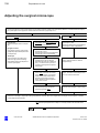
Control panel and menu overview
The control panel consists of graphic display (1) with membrane keyboard
(3). All functions can be interactively controlled using menus. The display
shows the selected functions and settings. Using control buttons (3) you
can move through the menus and activate a selection field. The field activated is then highlighted by a dark background. Press enter button (4) to
confirm your selection or entry.
For entering, briefly press any of control buttons (3). In some settings, the
control buttons have a repeat function, i.e. constant pressing of a button
causes the command to be repeated.
The menus are clearly laid out and user-friendly. The name of the menu
is given in bar (2) at the bottom. At the right-hand end of the bar, a small
pictogram is shown for quick orientation. At the left-hand end of the bar,
the activation field (OK) is located. If the background of this field is dark,
press the enter button to confirm your entry.
The relationship between the menus is shown in the illustration on the opposite page.
Power switch (5)
for switching the system on and off. When the system has been switched
on, the green lamp in the switch is lit.
The power switch contains an automatic circuit breaker. If a short-circuit
occurs, the automatic circuit breaker will respond and switch the system
off.
1
2
4
3
5
G-30-1434-en
OPMI® Sensera on S7 Suspension Systems
Issue 10.0
Printed on 30. 01. 2009
83
Description
Version ......
300 mm
Please wait ...
USER 1
USER 2
NONE
USER 3
NONE
50 %
1,4
50 %
Off
Off
300 mm
50 %
Off
50 %
Off
Off
4,9 x
300 mm
20 %
Close
Standard
+2
Off
AutoEnter
White Balance Press
Freeze/Live
Ready
Live
Config
Small
Off
Off
OSD
55 mm
Off
+ 0,00
+ 0,00
12,5 x
12,5 x
G-30-1434-en
OPMI® Sensera on S7 Suspension Systems
Issue 10.0
Printed on 30. 01. 2009
84
Description
Structure of the menus
Notes:
– If no entry is made for about 30 seconds, the preceding menu will automatically reappear.
–
Firmware release 1.1
Please wait ...
The data you have entered or changed will not be saved until you
press the OK button or the enter button, or when the preceding menu
appears after approx. 30 seconds because no further entries have
been made.
Start of menu
After you have switched on the system, the software is loaded. The
growing size of the ZEISS logo indicates that this loading process is still
in progress. The release number is displayed in the top left corner. The
system then performs a self-test.
After successful completion of the test, the "User Selection" menu is automatically displayed.
User menu
The User menu comprises one standard profile and three other user profiles.
When a user profile is selected, the system imports the settings stored
under this profile, e.g. focusing speed, zoom link setting, zoom speed and
handgrip settings. The stored start values ("Start at") for the magnification
factor, the focus position and the brightness are automatically set. The
three user profiles are used to adjust these settings for different users.
USER 1
USER 2
USER 3
When the system is started up for the first time, the Standard User is displayed; at every subsequent start-up, the user active last is displayed.
Notes:
– The Standard User profile allows the adjustment of settings, but these
settings cannot be saved (fixed factory settings).
–
G-30-1434-en
In the Standard User profile, all "Start at" fields are deactivated. No bar
is displayed; it is not possible to adjust any settings.
OPMI® Sensera on S7 Suspension Systems
Issue 10.0
Printed on 30. 01. 2009
85
Description
1
Dr. L. Weber
Dr. L. Weber
Edit User menu
Three different users or applications (e.g. larynx, nose, ear) and their profiles can be stored in the User menu. The Edit User menu allows you to
enter your personal user name. When Edit icon (1) after the user name is
activated, the input keyboard is displayed. This keyboard allows you to
enter a 12-digit user name or application name. After entering the name,
activate OK button (2) using the arrow buttons and press the enter button
to save the name entered.
A user or application name is displayed in the input field. If no name has
been entered, only User 1, 2 or 3 will be displayed.
After selecting a user or an application, press the enter button to return to
the Surgery menu.
Functions of buttons:
2
–
Press Edit button (1) to call the input keyboard and to activate the input function.
–
Select the individual characters using the arrow buttons and accept
the characters by pressing the enter button.
Delete one or more characters from right to left by pressing the
enter button.
Space Space bar; press the enter button to insert a blank space .
Inverse, switches to capital letters and back again when the
enter button is pressed.
<>
Cursor control, for insertion or deletion of individual characters
in the text.
Note:
You must activate OK button (2) using the arrow buttons and then press
the enter button to save the name entered under the selected User. After
selecting a user or an application, press the enter button to return to the
Surgery menu.
G-30-1434-en
OPMI® Sensera on S7 Suspension Systems
Issue 10.0
Printed on 30. 01. 2009
86
Description
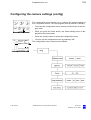
Surgery menu
4.9 x
300 mm
20 %
Standard
The Surgery menu is constantly displayed during operation. The menu includes the icons (from left to right) for the following menus: Zoom, Focus,
Illumination. Below: User, Options, Video and Balance. The displays
below the zoom, focus, illumination and user icons show the current settings for total magnification, working distance, brightness level and selected User.
Note:
– The display shows the name of the user or application shortened to 10
characters.
–
The readings displayed are rounded values which are only provided
for information, not for measurement purposes.
Use the control buttons to activate the icon required and press the enter
button to access the respective menu.
Zoom menu
You can adjust the settings for the following functions in the Zoom menu:
50 %
1,4
Speed:
The zoom speed from minimum to maximum speed from 5 % to 100 % in
steps of 5 %.
Start at:
The zoom start value. Enter the magnification factor at which the zoom
system should start when the system is switched on or is switched to a
different user. The magnification factor can be set and stored from γ = 0.4
x to γ =2.4x in steps of 0.1.
Note:
γ is only the magnification factor of the zoom system. The total magnification provided by the system is also determined by the eyepieces and the
working distance used.
•
Activate the function desired (Speed or Start at) and move the indicator bar using one of the arrow buttons (
, ) until the reading required is displayed in the field at the top.
•
Press the enter button to save the value set and to return to the Surgery menu. If you do not press any button, the display will automatically jump back to the Surgery menu after approx. 30 seconds.
Note:
In the Standard User profile, all "Start at" fields are deactivated. No bar is
displayed; it is not possible to adjust any settings.
G-30-1434-en
OPMI® Sensera on S7 Suspension Systems
Issue 10.0
Printed on 30. 01. 2009
87
Description
Focus menu
You can adjust the settings for the following functions in the Focus menu:
On
300 mm
50 %
On
Speed:
The focusing speed from minimum to maximum speed from 5 % to 100 %
in steps of 5 %.
Focus
On
On
G-30-1434-en
Zoom Link:
The Zoom Link function allows the focusing speed to be coupled to the
current magnification. This means that the focusing speed is automatically reduced when a high magnification is used. Whether the Zoom Link
function has been activated or deactivated is stored in the respective user
profile.
Start at:
Focus start value. Adjust the working distance at which the focusing
system should start when you call your user profile. The setting can be adjusted and stored from 200 to 415 mm in steps of 1 mm.
•
Activate the function desired and move the indicator bar using one of
the arrow buttons ( , ) until the reading required is displayed in the
field at the top.
•
Press the enter button to save the value set and to return to the Surgery menu. If you do not press any button, the display will automatically jump back to the Surgery menu after approx. 30 seconds and
save the values set.
OPMI® Sensera on S7 Suspension Systems
Issue 10.0
Printed on 30. 01. 2009
88
Description
Illumination menu
You can adjust the settings for the following functions in the Illumination
menu:
Zoom Link
On
50 %
50 %
On
Illumination
On
On
Intensity:
The illumination intensity from minimum to maximum brightness from
5 % to 100 % in steps of 5 %. This setting can be adjusted for the xenon
illumination and the halogen illumination.
Start at:
Brightness start value. Use one of the arrow buttons ( , ) to adjust the
illumination intensity in percent. The xenon or halogen lamp will then go
on at this brightness level after activation.
The "Start at" field will only be active if Zoom Link is in the Off position. If
Zoom Link is On, the "Start at" field will not be active. No bar is displayed;
it is not possible to adjust any settings.
Zoom Link:
Automatic brightness control. When this function is active (ON), the illumination is adjusted in such a way that the user is provided with a subjectively constant brightness level in the eyepiece, regardless of the zoom
factor set. Whether the Zoom Link function has been activated or deactivated is stored in the respective user profile.
•
G-30-1434-en
Press the enter button to save the value set and to return to the Surgery menu. If you do not press any button, the display will automatically jump back to the Surgery menu after approx. 30 seconds and
save the values set.
OPMI® Sensera on S7 Suspension Systems
Issue 10.0
Printed on 30. 01. 2009
89
Description
Options menu
Activate the Options icon and press the Enter button to access the Options menu. The Options menu comprises the following submenus (from
the top):
–
Image Capture menu
–
Handgrip Settings menu
–
Foot Control menu
–
Binocular Settings menu
–
Eyepiece Settings menu
–
Autofocus menu (option)
Image Capture menu
Image Capture permits you to save, view and delete image data in the
JPEG or TIFF format.
•
Select the Options icon in the Surgery menu and press the Enter button.
•
Select Image Capture in the Options menu and press the Enter button.
File name inquiry
The Image Capture menu permits you to assign a name to the saved
image. This name is saved and remains valid until it is deleted or
changed. To prevent that a wrong name is assigned to an image, the
system checks whether the entered name already exists. If no name is
found, the inquiry is skipped. Íf the name is found, the user is requested
to specify whether the name should be retained or deleted.
If no name has been saved, the inquiry menu is not displayed.
–
Preserve file name = the current file name is retained, the system
goes to the Surgery mode.
–
Delete file name = the file name is deleted, the system goes to the
Surgery mode.
Use the cursor to select the option required, and activate it with the Enter
button.
Note:
The display remains visible until an entry has been made.
G-30-1434-en
OPMI® Sensera on S7 Suspension Systems
Issue 10.0
Printed on 30. 01. 2009
90
Description
Image Capture menu
Note:
The number of images that can be saved on the USB memory stick is only
limited by the USB stick capacity.
Store function
The video image currently displayed can be saved on the USB memory
stick by selecting the Store option and pressing the Enter button.
For the store settings see page 146.
Index option
The Index option permits you to access the graphic index, where saved
images are displayed in the form of 12 distortion-free, demagnified images (thumbnails) per screen page.
For the Index functions, see page 170.
Press the Enter button to return to the graphic index.
Press the Enter button to exit the graphic index and to switch to the live
image mode.
If no images are available, the error message "No Images - Check USB
Stick" is displayed.
Config menu
The Config menu permits you to configure the Image Capture function.
For the Config menu see page 144.
G-30-1434-en
OPMI® Sensera on S7 Suspension Systems
Issue 10.0
Printed on 30. 01. 2009
91
Description
1
2
Handgrip Settings menu
This menu allows you to assign one of the listed functions to each of the
four buttons (A, B, C, D) for every user or application:
–
Light on/off: switching the illumination on and off.
–
Light +/-: adjusting the brightness level of the illumination.
–
Video Capture: triggering the device connected to the Remote socket
(on the suspension system's connector panel).
If the USB option is integrated, Video Capture acts on a connected,
external storage system (USB stick) and is therefore assigned the additional identification Ext. (Ext. Video Capture).
–
Photo: triggering an electrical contact in the suspension system. Here,
a camera can be connected (option).
–
Autofocus: triggering the SpeedFokus autofocus option.
–
Video Gain +/-: adjusting the brightness level of the integrated video
system (option).
–
OSD on/off: activating/deactivating the on-screen display of the integrated video system (option).
–
"Freeze/Live": the current live video image is frozen and displayed as
a full-screen freeze frame on the monitor.
If the USB option is present, the designation of the Freeze/Live function is Freeze/Store.
Freeze/Live
Note:
The Video Gain +/- and the OSD on/off functions are only offered for selection if your system is equipped with an integrated video camera (option). Without an integrated video camera (option), these fields remain
blank.
In addition, you can either assign the same functions to both handgrips
(button (1)) or assign different functions to the left and right handgrip
(button (2)).
Assignment of functions:
Use the arrow buttons ( , ) to select the function required from the
table. Use the arrow buttons ( , ) to select the handgrip button required (A-D). After you have pressed the enter button, a tick ( ) indicates that the selected function has been assigned to the selected button .
When you press the enter button again, your selection is saved and you
return to the Surgery menu.
Foot Control menu
Your suspension system permits the connection of a foot control panel
(option). This menu allows you to assign one of the listed functions to
each of the buttons C and D on the foot control panel for every user:
G-30-1434-en
OPMI® Sensera on S7 Suspension Systems
Issue 10.0
Printed on 30. 01. 2009
92
Description
–
Video Capture: triggering the device connected to the Remote socket
(on the suspension system's connector panel).
–
Autofocus: triggering the SpeedFokus autofocus option.
–
Video Gain +/-: adjusting the brightness level of the integrated video
system (option).
–
OSD on/off: activating/deactivating the on-screen display of the integrated video system (option).
Note:
The Video Gain +/- and the OSD on/off functions are only offered for selection if your system is equipped with an integrated video camera (option). Without an integrated video camera (option), these fields remain
blank.
Assignment of functions:
Use the arrow buttons ( , ) to select the function required from the
table. Use the arrow buttons ( , ) to select the button required (C or
D). After you have pressed the enter button, a tick ( ) indicates that the
selected function has been assigned to the selected button .
When you press the enter button again, your selection is saved and you
return to the Surgery menu.
G-30-1434-en
OPMI® Sensera on S7 Suspension Systems
Issue 10.0
Printed on 30. 01. 2009
93
Description
Binocular Settings menu
If you select Binocular Setting in the Options menu, the following three
setting options are available:
–
Selection of the eyepieces used (10x or 12.5x)
–
Selection of the tube used (170 mm or 200 mm)
–
Activation of the PD and Diopter Settings submenu
The selection of the tube and eyepieces is required for the correct display
of the system's total magnification in the Surgery menu. Use the arrow
buttons ( , ) to select the relevant tube and eyepiece type. Save the
eyepiece type and tube type used by pressing the enter button.
If you select the "PD and Diopter Settings" function, the program
branches to the appropriate subprogram.
Press the enter button to save the value set and to return to the Surgery
menu. If no entry is made, the display will automatically jump back to the
Surgery menu after approx. 30 seconds.
PD and Diopter Settings"
This menu only has a memory function. It provides sliders which enable
each user to set his/her interpupillary distance and prescription using one
of the arrow buttons ( , ) and to save these values. No motorized setting is made on the eyepieces or tube.
This function is intended to allow OR staff to adjust the surgical microscope to the surgeon's settings before the procedure and, if necessary, to
retrieve or change the stored values.
–
You can set the interpupillary distance in 1 mm steps from 55 mm to
80 mm.
–
When using widefield eyepieces with a magnetic coupling, you can set
your prescription between -8 D and +8 D.
If no entry is made, the display will automatically jump back to the Surgery
menu after approx. 30 seconds.
G-30-1434-en
OPMI® Sensera on S7 Suspension Systems
Issue 10.0
Printed on 30. 01. 2009
94
Description
SpeedFokus autofocus option
The SpeedFokus autofocus option permits you to select and automatically focus on a feature in the ROI (region of interest, measuring field) in
the image of the surgical field.
The SpeedFokus autofocus function is based on the evaluation of the
video image contrast: during focusing of the microscope's Varioskop optics, SpeedFokus continuously determines the video image contrast in the
selected ROI. In this way, SpeedFokus controls the microscope's Varioskop optics and adjusts it to the point of maximum contrast, corresponding to the point of maximum image definition.
Autofocus menu
The Autofocus menu offers you the following functions for selection:
–
ROI, on/off: activating / deactivating the ROI display
–
ROI Size, smal/medium/large: selecting the ROI size
–
ROI Position: branching to the AF - ROI Position submenu to define
the ROI position
–
Camera Position, left/right: entering the orientation of the external video camera.
–
Advanced Settings: branching to the Advanced Settings submenu to
enter the technical data of the external video camera.
Notes:
– The "Camera Position left/right" and "Advanced Settings" functions
are only offered for selection if your system is equipped with an external video camera. If you have an integrated video camera, these fields
remain blank.
–
As long as you are entering any settings in the Autofocus menu or its
submenus, the ROI is displayed as a square frame in the video image
on the monitor. A few seconds after your last action, the frame disappears from the screen.
Menu item "ROI, on/off"
The position and size of the ROI are displayed on the video monitor in the
form of a square frame. Use the "ROI on/off" function to activate or deactivate this display on the video monitor.
G-30-1434-en
OPMI® Sensera on S7 Suspension Systems
Issue 10.0
Printed on 30. 01. 2009
95
Description
Menu item "ROI Size, small/medium/large"
Permits you to select the ROI size.
Three different ROI sizes are available for selection: small (20x20 pixels),
medium (36x36 pixels) and large (50x50 pixels).
The default setting for the Standard User is the large ROI. You can
change the size of the ROI, but the change cannot be saved for the
Standard User.
For specific users, the ROI size can be set and saved for each user as
required.
Submenu "AF - ROI Position"
This submenu permits you to define the ROI position within the microscope's field of view.
When you start the suspension system, the ROI is always positioned at
the center of the field of view. The ROI is visualized as a square in the
graphic display. Use the arrow keys to shift the ROI.
Press the OK button to return to the Autofocus menu. If you do not press
any of the buttons, the display will automatically return to the Surgery
menu after approx. 20 seconds.
Menu item "Camera Position":
If you are using an external video camera, the orientation of the video
camera must be known to the SpeedFokus autofocus option.
Note:
This function is only available in systems equipped with an external video
camera.
Caution:
The video image must have the same orientation as the image in the main
eyepieces of the surgical microscope.
In addition, SpeedFokus needs the information whether the video camera
is connected on the left or right, i.e. whether the beam splitter projects into
the main beam path from the left or right, to be able to perform corrections
in the right direction during the focusing process.
Submenu "Advanced Settings"
Notes:
– This submenu is only available in systems equipped with an external
video camera.
–
This submenu contains camera-specific settings. These settings only
need to be changed when a different video camera is installed.
–
The SpeekFokus autofocus option does not function properly if parameters have not been correctly set.
The "Advanced Settings" submenu contains the following camera-specific settings:
G-30-1434-en
OPMI® Sensera on S7 Suspension Systems
Issue 10.0
Printed on 30. 01. 2009
96
Description
–
Video Focal Length
–
Camera Chip Size (size of the CCD array)
Video Focal Length and Camera Chip Size (size of the CCD array):
These settings must conform to the technical specifications of the video
camera used.
G-30-1434-en
OPMI® Sensera on S7 Suspension Systems
Issue 10.0
Printed on 30. 01. 2009
97
Description
Video Settings menu (option)
The Video Settings menu permits you to configure the integrated 1CCD
video camera in the Config submenu, and to enter or edit text using the
OSD function.
AutoEnter
Auto
White Balance Press
+2
Freeze/Live
Ready
Live
Ready
Config
Small
Off
OSD
Off
Activate the Video icon and press the enter button to access the Video
Settings menu. It contains selection fields for configuring the functions of
the integrated video system.
Use arrow buttons ( , ) to move from White Balance to
Freeze/
Live
OSD OK.
The function and the adjusting possibilities of the individual selection
fields are explained in the following.
Gain
When you open the Video Settings menu, the Gain setting is active. Use
the arrow buttons ( , ) to adjust the brightness of the video image as
required on the slider displayed.
Using the arrow button ( ) you can jump from GAIN to the White Balance
selection field.
+2
AutoEnter
Auto
White Balance Press
Freeze/Live
Ready
Ready
Live
Config
Small
Off
OSD
Off
White balance
The system adjusts the video signal in such a way that white areas in the
surgical field are also white in the video image.
To achieve this, place a suitable white object (e.g. a piece of white paper
with a matte surface) under the microscope and focus the microscope on
it, using a medium brightness level.
After pressing the enter button, the user is requested to place a white
sheet of paper under the microscope and to start the white balance procedure by pressing the enter button.
During the white balance procedure (display: "White Balance in Process")
all buttons are disabled.
After successful completion of the white balance procedure, the confirmation "White Balance OK" is displayed.
Otherwise, the monitor displays "White Balance Failed". Check the settings described above and repeat the white balance procedure.
After completion of the white balance procedures, all buttons are enabled
again. The determined values are stored and are available after every restart.
G-30-1434-en
OPMI® Sensera on S7 Suspension Systems
Issue 10.0
Printed on 30. 01. 2009
98
Description
+2
AutoEnter
Auto
White Balance Press
Freeze/Live
Ready
Live
Ready
Config
Small
Off
OSD
+2
Off
AutoEnter
Auto
White Balance Press
Freeze/Live
Ready
Live
Ready
Config
Small
Off
OSD
Off
G-30-1434-en
Freeze/Live setting
The freeze button permits you to freeze the current live video image and
to display it as a full-screen freeze frame on the video monitor. During this
time, the text "freeze" is displayed in the upper left corner.
When you press the live button, the current live video image is displayed
again on the monitor, and the text "freeze" disappears.
Config
The configuration menu permits you to set various functions to meet your
specific needs.
You access the configuration menu by pressing the Config button.
The different setting options for the configuration of the user program are
described in the chapter "Preparations for use", see page 139.
The camera is delivered with a default configuration (factory settings).
OPMI® Sensera on S7 Suspension Systems
Issue 10.0
Printed on 30. 01. 2009
99
Description
OSD menu (On Screen Display)
+2
AutoEnter
Auto
White balance Press
Freeze/Live
Ready
Ready
Live
Config
Small
Off
OSD
1
Off
2
3
On
On
Off
On
Off
Off
The OSD function allows you display freely selectable texts, a ruler and
microscope parameters such as magnification and working distance on
the video monitor. This information is included in the image when the
screen shot is saved or printed. You can delete the individual displays by
activating the corresponding selection field and selecting "Off" with the
enter button. You can delete all displays from the screen by setting the
OSD to "Off".
Note:
If Off has been entered for all selection fields, no display will appear even
if OSD is in the ON mode.
Text fields (1) and (2) can be edited. In the Edit menu, for example, you
can enter the name of the hospital and your personal user name. When
you activate Edit button (3) after the text field, the input keyboard is displayed. This keyboard allows you to enter any 12-character text.
Functions of buttons:
–
When the input keyboard has been activated with Edit button (3), the
input function is active.
–
Select the individual characters using the arrow buttons and accept
the characters by pressing the enter button.
Delete one or more characters from right to left by pressing the
enter button.
Space Space bar: press the enter button to insert a blank space.
Inverse: switches to capital letters and back again when the
enter button is pressed.
<>
G-30-1434-en
Cursor control: for insertion or deletion of individual characters
in the text.
OPMI® Sensera on S7 Suspension Systems
Issue 10.0
Printed on 30. 01. 2009
100
Description
On
Off
On
On
If "Ruler" selection field (4) has been activated, a ruler including a dimension is displayed in the bottom left corner of the screen. The ruler and the
dimension specified automatically change with the zoom and focus settings. The numerical value of the dimension displayed can be 2.5 / 5 /10
/ or 20 mm.
On
On
If "Zoom" selection field (5) has been activated, the current magnification
factor of the overall system will be displayed at the bottom of the screen.
If "Focus" selection field (6) has been activated, the current working distance of the overall system will be displayed at the bottom of the screen.
456
Notes:
– The zoom and focus readings are identical to the readings shown on
the graphic display of the control panel.
–
The length of the ruler is independent of the eyepiece magnification.
–
The ruler only relates to the image plane focused.
–
The readings displayed are rounded values and are only provided for
display and not for measuring purposes.
–
The OSD ruler is no measuring instrument. It is only used to show the
size ratio and must not be used for diagnostic purposes.
1
Hospital .....
2
Dr. ....
20 mm
3,1 x
227 mm
5
6
4
G-30-1434-en
OPMI® Sensera on S7 Suspension Systems
Issue 10.0
Printed on 30. 01. 2009
101
Description
Balance menu
The Balance menu has been designed as a user prompt and consists of
six images explaining the balancing procedure. You can scroll through the
Balance menu using the arrow buttons ( , ). The OK button has no
function.
Press the enter button or the arrow buttons ( , ) several times to return
to the Surgery menu.
The balancing procedure is described in the "Preparations for use"
chapter under "Adjusting the system"
G-30-1434-en
OPMI® Sensera on S7 Suspension Systems
Issue 10.0
Printed on 30. 01. 2009
102
Description
1
User 1
NONE
User 2
TwinER
User 3
TwinER
Laser menu
In the User selection menu, you can access the Laser selection menu via
the respective Edit button using the arrow button ( ). Here, the working
distance (focus) of the Varioskop in the surgical microscope is adjusted to
the working distance of the TwinER (option) or CO2 laser, and the system
is switched to the motorized external focus module (option) .
After you have activated Laser menu button (1), a pull-down menu is automatically opened in the display.
Note: The pull-down menu will be automatically opened if you approach
from the left with the arrow button ( ). If you select the field using the
( , )arrow buttons, the pull-down menu can be opened by pressing
the enter button.
Using the arrow buttons (
Laser TwinER.
,
) , you can jump to
None
CO2
By activating one of the options None, CO2 Laser, TwinER and pressing
the enter button, you can transfer your selection to Laser menu (1).
When you select "CO2 Laser", you access the "Focus Laser" menu.
Use the arrow buttons ( , ) to adjust the working distance (focus) of
the micromanipulator used. After you have pressed the OK button and
confirmed the user, the Varioskop is automatically adjusted to the selected working distance and deactivated. At the same time, the external
focus module is activated if this option has been integrated, see also the
notes on page 136.
Warning!
It is absolutely vital that the focal planes of the surgical microscope and of
the laser are identical!
Check this after mounting the micromanipulator, before every surgical
procedure (without patient) and before every use of the laser by directing
a trial laser shot at a wooden spatula located in the focal plane. If the
alignment is correct, the laser is focused precisely on the working plane,
and its therapy beam displays its maximum effect. If this is not the case,
you have to correct the working distance in the Laser menu.
Press the enter button to save the value set and to return to the Surgery
menu. If you do not press any button, the display will automatically jump
back to the Surgery menu after approx. 30 seconds.
G-30-1434-en
OPMI® Sensera on S7 Suspension Systems
Issue 10.0
Printed on 30. 01. 2009
103
Description
When you select "TwinER" you access the "Focus TwinER" menu (option).
The "Focus TwinER" menu only contains the displays:
–
Internal Focus is fixed
–
external focus active.
The Varioskop automatically adjusts to the focal length of the TwinER
laser and switches off. At the same time, the external focus module becomes operative. When you press the laser micromanipulator focus
switch, the external focus module is automatically activated. Any manual
change of the focus triggers an error message.
This display automatically jumps back to the User menu after about 30
seconds. If you do not press any button, the display will automatically
jump back to the Surgery menu after approx. 30 seconds.
Malfunctions (Error message menu)
1
HR:-9005
HANDGRIP RIGHT
handgrip button pressed
Cancel
This window appears on your display when a malfunction or incorrect operation has occurred. At the same time, this is also indicated by three
beeps.
In addition, the type of malfunction present and a code number are displayed in field (1).
The letters in front of the code numbers indicate the system component
where the malfunction has occurred:
S - suspension system, HR - handgrip right, HL - handgrip left, F - foot
control panel, V - video, O - surgical microscope, C - (core) software.
This code number permits you to identify the malfunction that has occurred,
e.g.:
HR:-9005
HANDGRIP RIGHT
handgrip button pressed
You can delete the error message by pressing the enter button. Internally,
the system keeps a record of the malfunctions occurred.
If you cannot eliminate the malfunction, you may perhaps be able to continue working by switching off the suspension system or separating the
plug-in connection to the surgical microscope (see the emergency instructions on page 96).
G-30-1434-en
OPMI® Sensera on S7 Suspension Systems
Issue 10.0
Printed on 30. 01. 2009
104
Description
Foot control panel (option)
Intended use
The foot control panel permits you to operate various functions of a suspension system or surgical microscope. The assignment of functions to
the controls on the foot control panel is described on the next page. Only
functions provided in the system configuration used (suspension system,
surgical microscope) can be controlled.
Design
The foot control panels with 8 and 14 functions are equipped with two
rocker switches (1) used to control the ”zoom” and ”focus” functions. The
switches for these functions are located on one side, allowing you to control the function using toe/heel movement without having to shift your foot.
Bridge (3) between two rocker switches (1) serves as a support to rest
your foot on.
Connector (2) is used to connect the foot control panel to the appropriate
connector on a suspension system or a wall socket.
The foot control panel is provided with a waterproof rubber cover.
The illustration shows the 14-function foot control panel. Depending on
the configuration involved, an 8-function foot control panel can also be
connected.
G-30-1434-en
OPMI® Sensera on S7 Suspension Systems
Issue 10.0
Printed on 30. 01. 2009
105
Description
2
1
3
1
G-30-1434-en
OPMI® Sensera on S7 Suspension Systems
Issue 10.0
Printed on 30. 01. 2009
106
Description
Foot control panel with 14 functions
The illustration shows the standard assignment of functions to the foot
control panel with 14 functions. The focus/zoom assignment can be
changed by our service staff, on request.
1
No function
2
Button A: reducing the lamp brightness
3
Button C: function as assigned in the Options menu
4
ZOOM : reducing magnification, increasing the field of view
(alternatively FOCUS : increasing the working distance)
5
ZOOM
6
Illumination on/off
7
Illumination on/off
8
FOCUS : increasing the working distance (alternatively ZOOM
reducing magnification, increasing the field of view)
9
FOCUS
: increasing magnification, reducing the field of view
:
: reducing the working distance
10 Button D: function as assigned in the Options menu
11 Button B: increasing the lamp brightness
1
A
2
11
B
C
3
10
D
4
9
5
8
6
7
G-30-1434-en
OPMI® Sensera on S7 Suspension Systems
Issue 10.0
Printed on 30. 01. 2009
107
Description
Foot control panel with 8 functions
The illustration shows the standard assignment of functions to the foot
control panel with 8 functions.
The focus/zoom assignment can be changed by our service staff, on request.
1
Reducing the lamp brightness
2
No function
3
ZOOM : Reducing magnification, increasing the field of view
(alternatively FOCUS : Increasing the working distance)
4
ZOOM
5
Button C: Function as assigned in the Options menu
6
Button D: Function as assigned in the Options menu
7
FOCUS : Increasing the working distance (alternatively ZOOM
Reducing magnification, increasing the field of view)
8
FOCUS
9
No function
: Increasing magnification, reducing the field of view
: Reducing the working distance
10 Increasing the lamp brightness
C
G-30-1434-en
1
10
2
9
3
8
4
7
5
6
OPMI® Sensera on S7 Suspension Systems
D
Issue 10.0
Printed on 30. 01. 2009
:
108
Description
G-30-1434-en
OPMI® Sensera on S7 Suspension Systems
Issue 10.0
Printed on 30. 01. 2009
109
Preparations for use
Preparations for use
G-30-1434-en
Attaching the equipment
112
Mounting the tube and eyepieces
112
Connections
114
Connecting the strain relief device
114
Connecting the suspension system - S7 floor stand
116
Connecting the suspension system - S7 ceiling mount with
rigid column
118
Connecting the suspension system - S7 ceiling mount with
lifting column
120
Connecting video monitor and MediLive ImageBox (option)
122
Adjusting the system - S7 floor stand
124
Balancing the suspension arm
124
Setting the limit of downward travel of the suspension arm
124
Adjusting the system - S7 ceiling mount with rigid column
126
Balancing the suspension arm
126
Setting the limit of downward travel of the suspension arm
126
Adjusting the system - S7 ceiling mount with lifting column
128
Setting an ergonomic working height
128
Balancing the suspension arm (ceiling mount with lifting column)
130
Setting the limit of downward travel of the suspension arm
130
Balancing the surgical microscope
132
Surgical microscope with a laser micromanipulator
136
Adjusting the surgical microscope
138
Configuring the camera settings (config)
139
OPMI® Sensera on S7 Suspension Systems
Issue 10.0
Printed on 30. 01. 2009
110
Preparations for use
G-30-1434-en
Configuring Image Capture
144
Relocating the S7 floor stand
152
OPMI® Sensera on S7 Suspension Systems
Issue 10.0
Printed on 30. 01. 2009
111
Preparations for use
G-30-1434-en
OPMI® Sensera on S7 Suspension Systems
Issue 10.0
Printed on 30. 01. 2009
112
Preparations for use
Attaching the equipment
Mounting the tube and eyepieces
•
Bring the suspension arm in a position convenient for you and tighten
friction adjustment knob (1).
Note:
• Give securing screw (3) a few turns to loosen it.
•
Remove cover (2) and store it in a safe place.
•
Place binocular tube (4) on the microscope body and firmly tighten securing screw (3).
•
You can install other units between the binocular tube and the microscope body. Lock these units in position in the same way using securing screw (3).
•
Insert widefield eyepieces (6) as far as they will go in mounts (5) intended for them in the binocular tube. The magnetic coupling reliably
secures them in position.
Note:
If you wish to use documentation equipment, we can supply an eyepiece
with a reticle to aid focusing. The retrofitting of a reticle to an eyepiece
can only be performed in the factory or by our service staff. Always install
the eyepiece with the reticle in the binocular tube on the same side as the
documentation equipment.
Caution:
G-30-1434-en
–
Before every use and after re-equipping the instrument, make sure
that binocular tube (5) is securely locked in position. Make sure that
securing screws (2) and (4) have been firmly tightened!
–
Re-adjust the balance of the suspension arm after every change of the
equipment.
OPMI® Sensera on S7 Suspension Systems
Issue 10.0
Printed on 30. 01. 2009
113
Preparations for use
1
G-30-1434-en
2
3
4
OPMI® Sensera on S7 Suspension Systems
5
6
7
Issue 10.0
Printed on 30. 01. 2009
114
Preparations for use
Connections
Connecting the strain relief device
Note:
You can secure the power plug and the multipoint connector of the
switching component against inadvertent loosening by installing the two
cables in strain relief device (1).
After you have mounted strain relief device (1), the cables must have the
following lengths:
–
320 mm from the strain relief device up to and including power connector (9).
–
320 mm from the strain relief device up to connector (10) of the foot
control panel.
•
Form a loop with the cable as shown in (3).
•
Open flap (4).
•
Feed the cable through opening (5).
•
Close flap (6).
•
Tighten the cable until it encloses flap (7).
•
Check the length of the cable.
1
G-30-1434-en
OPMI® Sensera on S7 Suspension Systems
Issue 10.0
Printed on 30. 01. 2009
115
Preparations for use
2
3
5
6
4
7
8
320 mm
9
10
G-30-1434-en
OPMI® Sensera on S7 Suspension Systems
Issue 10.0
Printed on 30. 01. 2009
116
Preparations for use
Connecting the suspension system - S7 floor stand
•
Check the voltage indicated at (5).
Caution:
The voltage of the stand is factory-set to the rated voltage used in the
country of destination. The rated voltage indicated at window (5) must correspond to the rated voltage available at the site of installation. If this is
not the case, re-adjust the sliding switch using a suitable tool.
Note:
Make sure that the unit has been switched off at the power switch before
plugging in or unplugging connectors at (3) and (4).
G-30-1434-en
•
Plug the connector of the foot control panel into connector (2) on the
stand if you wish to use a foot control panel.
•
Connect the stand to line power by plugging the power cord supplied
for this purpose into (4). Only use power outlets which are provided
with a properly connected protective ground contact.
•
If required, connect the stand to the potential equalization contact in
the OR using potential equalization pin (1).
OPMI® Sensera on S7 Suspension Systems
Issue 10.0
Printed on 30. 01. 2009
117
Preparations for use
1
G-30-1434-en
2
3
4
OPMI® Sensera on S7 Suspension Systems
5
Issue 10.0
Printed on 30. 01. 2009
118
Preparations for use
Connecting the suspension system - S7 ceiling mount with
rigid column
•
Check the voltage indicated at (2).
Caution:
The voltage of the suspension system is factory-set to the rated voltage
used in the country of destination. The rated voltage indicated at window
(2) must correspond to the rated voltage available on the site of installation. If this is not the case, re-adjust the sliding switch using a suitable tool.
•
G-30-1434-en
Plug the connector of the foot control panel (option) into connector (1)
of the suspension system.
OPMI® Sensera on S7 Suspension Systems
Issue 10.0
Printed on 30. 01. 2009
119
Preparations for use
1
G-30-1434-en
OPMI® Sensera on S7 Suspension Systems
2
Issue 10.0
Printed on 30. 01. 2009
120
Preparations for use
Connecting the suspension system - S7 ceiling mount with
lifting column
•
Check the voltage indicated at (2).
Caution:
The voltage of the suspension system is factory-set to the rated voltage
used in the country of destination. The rated voltage indicated at window
(2) must correspond to the rated voltage available on the site of installation. If this is not the case, re-adjust the sliding switch using a suitable tool.
•
G-30-1434-en
Plug the connector of the foot control panel (option) into connector (1)
of the suspension system.
OPMI® Sensera on S7 Suspension Systems
Issue 10.0
Printed on 30. 01. 2009
121
Preparations for use
1
G-30-1434-en
OPMI® Sensera on S7 Suspension Systems
2
Issue 10.0
Printed on 30. 01. 2009
122
Preparations for use
Connecting video monitor and MediLive ImageBox (option)
Note:
The image quality obtained with Y/C connections and cables shorter than
10 m is always better than that obtained with BNC connections of the
same length. If cable lengths exceed 10 m, the image quality provided by
a Y/C connection will decrease markedly; in these cases, only BNC connections should be used.
For this reason, position the individual units in such a way that you can
use Y / C connections. The Y/C connection provides the best image
quality, in particular for images recorded with the MediLive ImageBox.
If this is not possible, position the individual units in such a way that you
can use the Y/C cable at least for the video input port on the MediLive ImageBox.
Remote control of the MediLive ImageBox using freely configurable
buttons
The freely configurable handgrip buttons of the surgical microscope and
the freely configurable keys (C and D) on the foot control panel allow you
to control external units.
The signal generated by the configurable buttons/keys is present at the
Remote socket on the connector panel of the suspension system.
•
To enable the remote control function, connect the Remote socket on
the connector panel of the suspension system to the Remote socket
on the MediLive ImageBox.
Design
G-30-1434-en
1
Commercial video monitor
2
Commercial video recorders, video printers, video projectors
3
MediLive ImageBox
4
Connector panel of the suspension system
OPMI® Sensera on S7 Suspension Systems
Issue 10.0
Printed on 30. 01. 2009
123
Preparations for use
1
(Option)
1
VIDEO IN
VIDEO IN
2
2
BNC(FBAS)
Y/C
MediLive ImageBox
BNC(FBAS)
Y/C
Remote
3
4
4
G-30-1434-en
OPMI® Sensera on S7 Suspension Systems
Issue 10.0
Printed on 30. 01. 2009
124
Preparations for use
Adjusting the system - S7 floor stand
Balancing the suspension arm
Note:
Do not perform the balance setting until the surgical microscope and all
accessories have been mounted!
•
Move the suspension arm into its horizontal position and tightly hold it
with one hand.
•
Loosen knob (3) for adjusting the friction of the suspension arm's upward/downward movement.
•
Move the suspension arm slightly up and down. At the same time, turn
adjustment screw (1) until you think that the spring force is sufficient
to compensate for the weight of the surgical microscope and accessories. Continue to perform this adjustment until the surgical microscope
moves neither upward nor downward. The surgical microscope is fully
balanced when it remains stationary in all positions within the work area.
Note:
Turning the screw clockwise increases the spring force, turning it counterclockwise reduces the spring force.
Setting the limit of downward travel of the suspension arm
Warning!
The downward travel of the suspension arm must be limited in such a way
that the microscope cannot come into contact with the patient even if the
surgical microscope is inadvertently lowered.
G-30-1434-en
•
Loosen locking lever (2) for the upward/downward movement.
•
Lower the surgical microscope until it can be focused on the surgical
field (depending on the focal length of the objective lens), while at the
same time allowing for a sufficient safety distance from the surgical
field.
•
Firmly retighten locking lever (2) for the upward/downward movement.
OPMI® Sensera on S7 Suspension Systems
Issue 10.0
Printed on 30. 01. 2009
125
Preparations for use
•
Lower the surgical microscope again to its bottom stop and check the
safety distance.
Notes:
– The limit of downward travel is only effective in the lower part of the
suspension arm's range of vertical movement (starting from the arm's
horizontal position).
–
If you wish to use the suspension arm's full range of vertical movement, lower the suspension arm as far as it will go and then firmly
retighten locking lever (2).
1
G-30-1434-en
2
3
OPMI® Sensera on S7 Suspension Systems
Issue 10.0
Printed on 30. 01. 2009
126
Preparations for use
Adjusting the system - S7 ceiling mount with rigid column
Balancing the suspension arm
Note:
Do not perform the balance setting until the surgical microscope and all
accessories have been mounted!
•
Move the suspension arm into its horizontal position and tightly hold it
with one hand.
•
Loosen knob (3) for adjusting the friction of the suspension arm's upward/downward movement.
•
Move the suspension arm slightly up and down. At the same time, turn
adjustment screw (1) until you think that the spring force is sufficient
to compensate for the weight of the surgical microscope and accessories. Continue to perform this adjustment until the surgical microscope
moves neither upward nor downward. The surgical microscope is fully
balanced when it remains stationary in all positions within the work area.
Note:
Turning the screw clockwise increases the spring force, turning it counterclockwise reduces the spring force.
Setting the limit of downward travel of the suspension arm
Warning!
The downward travel of the suspension arm must be limited in such a way
that the microscope cannot come into contact with the patient even if the
surgical microscope is inadvertently lowered.
G-30-1434-en
•
Loosen locking lever (2) for the upward/downward movement.
•
Lower the surgical microscope until it can be focused on the surgical
field (depending on the focal length of the objective lens), while at the
same time allowing for a sufficient safety distance from the surgical
field.
•
Firmly retighten locking lever (2) for the upward/downward movement.
OPMI® Sensera on S7 Suspension Systems
Issue 10.0
Printed on 30. 01. 2009
127
Preparations for use
•
Lower the surgical microscope again to its bottom stop and check the
safety distance.
Notes:
– The limit of downward travel is only effective in the lower part of the
suspension arm's range of vertical movement (starting from the arm's
horizontal position).
–
1
G-30-1434-en
If you wish to use the suspension arm's full range of vertical movement, lower the suspension arm as far as it will go and then firmly
retighten locking lever (2).
2
3
OPMI® Sensera on S7 Suspension Systems
Issue 10.0
Printed on 30. 01. 2009
128
Preparations for use
Adjusting the system - S7 ceiling mount with lifting column
Setting an ergonomic working height
Bring the surgical microscope into a position convenient for you before
each surgical procedure, and set the optimum ergonomic working height
of the suspension system via the lifting column (without patient!).
As long as you keep selector switch (2) in the turned position, lifting
column (1) moves upward or downward, depending on the switch position. When you release the selector switch, the lifting column stops immediately.
•
Before raising or lowering the suspension system, make sure that
there is sufficient clearance from other objects so that any collision is
avoided.
Note:
The lifting column is used to move the microscope into position for surgery
prior to the surgical procedure.
Do not constantly move the lifting column up and down, since a thermal
cut-out will then automatically deactivate the drive motor. If this occurs,
the lifting column cannot be moved until the motor has cooled down.
Warning!
– Do not activate the lifting column during surgery!
G-30-1434-en
–
Do not use the lifting column for focusing.
–
Make sure that the patient is not put at risk or injured by the motorized
adjustment of the lifting column.
OPMI® Sensera on S7 Suspension Systems
Issue 10.0
Printed on 30. 01. 2009
129
Preparations for use
1
2
G-30-1434-en
OPMI® Sensera on S7 Suspension Systems
Issue 10.0
Printed on 30. 01. 2009
130
Preparations for use
Balancing the suspension arm (ceiling mount with lifting column)
Note:
Do not perform the balance setting until the surgical microscope and all
accessories have been mounted!
•
Move the suspension arm into its horizontal position and tightly hold it
with one hand.
•
Loosen knob (3) for adjusting the friction of the suspension arm's upward/downward movement.
•
Move the suspension arm slightly up and down. At the same time, turn
adjustment screw (1) until you think that the spring force is sufficient
to compensate for the weight of the surgical microscope and accessories. Continue to perform this adjustment until the surgical microscope
moves neither upward nor downward. The surgical microscope is fully
balanced when it remains stationary in all positions within the work area.
Note:
Turning the screw clockwise increases the spring force, turning it counterclockwise reduces the spring force.
Setting the limit of downward travel of the suspension arm
Warning!
The downward travel of the suspension arm must be limited in such a way
that the microscope cannot come into contact with the patient even if the
surgical microscope is inadvertently lowered.
G-30-1434-en
•
Loosen locking lever (2) for the upward/downward movement.
•
Lower the surgical microscope until it can be focused on the surgical
field (depending on the focal length of the objective lens), while at the
same time allowing for a sufficient safety distance from the surgical
field.
•
Firmly retighten locking lever (2) for the upward/downward movement.
•
Lower the surgical microscope again to its bottom stop and check the
safety distance.
OPMI® Sensera on S7 Suspension Systems
Issue 10.0
Printed on 30. 01. 2009
131
Preparations for use
Notes:
– The limit of downward travel is only effective in the lower part of the
suspension arm's range of vertical movement (starting from the arm's
horizontal position).
–
1
G-30-1434-en
If you wish to use the suspension arm's full range of vertical movement, lower the suspension arm as far as it will go and then firmly
retighten locking lever (2).
2
3
OPMI® Sensera on S7 Suspension Systems
Issue 10.0
Printed on 30. 01. 2009
132
Preparations for use
Balancing the surgical microscope
Warning!
Balance the completely equipped surgical microscope before surgery
without the patient.
To permit almost effortless guidance of the surgical microscope, the surgical microscope and the suspension system used must be correctly balanced. If the system is in an extremely unbalanced state, the unit can
move uncontrollably out of position. For this reason, hold the surgical microscope tightly at its handgrips before loosening the friction adjustment
knob on the suspension arm.
Adjusting the friction of the microscope's axis of rotation
•
Use knob (1) to adjust the friction of the microscope's axis of rotation.
Adjusting the lateral tilt motion
•
Loosen friction adjustment knob (3).
•
Use knob (2) to adjust the spring force in such a way that the surgical
microscope is balanced about its lateral tilt axis and remains stationary in the viewing direction required.
– If the surgical microscope tends to move clockwise, turn knob (2)
counterclockwise.
– If the surgical microscope tends to move counterclockwise, turn
knob (2) clockwise.
Adjusting the friction of the lateral tilt axis
•
G-30-1434-en
Use knob (3) to adjust the friction for the lateral tilt axis as required.
OPMI® Sensera on S7 Suspension Systems
Issue 10.0
Printed on 30. 01. 2009
133
Preparations for use
1
2
3
G-30-1434-en
OPMI® Sensera on S7 Suspension Systems
Issue 10.0
Printed on 30. 01. 2009
134
Preparations for use
Balancing the front-to-back tilt motion
For initial balancing or after a change of the accessories, proceed as follows:
Warning!
If the system is in an extremely unbalanced state, the unit can move uncontrollably out of position. For this reason, hold the surgical microscope
tightly at its handgrips before loosening the friction knob.
Zero position
•
Loosen friction knob (4).
•
Press button (1) until the motor of the balancing system stops. This
decouples the microscope body from its mount.
The microscope has been decoupled from its suspension and has
adopted its center-of-gravity position (zero position) if the white ring
with marking (3) does not move when you turn the microscope.
•
Please check that the white ring is really in the zero position. If this is
not the case, turn it manually to the zero position.
•
Press button (2).
Important: Allow the microscope to hang in its center-of-gravity position while you press button (2).
After approx. 15 seconds, the microscope body has again been coupled
on its suspension. You can check this: When you move the microscope
body, white ring (3) also moves.
•
Continue pressing key (2) and check whether the microscope body remains balanced in every tilt position. Depending on the accessories
attached, this can take some time (approx. 1 minute or longer). To
check this, slightly lift the microscope body and tilt it into different positions to see whether the microscope body has been correctly balanced.
•
If you have pressed button (2) for too long, you can correct the balance by pressing button (1).
Correcting the balance of the front-to-back tilt motion
After a slight change in the position of accessories (e.g. the angle of the
coobservation tube) it may become necessary to correct the balance setting.
G-30-1434-en
–
If the microscope body tends to tilt forward (in your direction), press
key (2).
–
If the microscope body tends to tilt backward, press key (1).
OPMI® Sensera on S7 Suspension Systems
Issue 10.0
Printed on 30. 01. 2009
135
Preparations for use
Adjusting the friction of the front-to-back tilt axis
Use knob (4) to adjust the friction of the front-to-back tilt axis as required.
2
2
1
1
2
1
3
4
G-30-1434-en
OPMI® Sensera on S7 Suspension Systems
Issue 10.0
Printed on 30. 01. 2009
136
Preparations for use
Surgical microscope with a laser micromanipulator
•
Please observe the separate user manual for your micromanipulator.
Before using the surgical microscope with a laser micromanipulator, you
must adjust the focal plane of the microscope (Varioskop) to the focal
plane of the micromanipulator.
Note:
The focal plane roughly corresponds to the working distance.
In the User selection menu, you can access the Laser selection menu via
the respective Edit button using the arrow button ( ) (see chapter: Description/Laser menu/CO2laser).
•
Use the arrow buttons ( , ) to adjust the working distance (focus)
of the Varioskop in the surgical microscope to the working distance of
your micromanipulator.
If the motorized fine focus (available as an option) has been integrated,
the motorized focusing function of the Varioskop automatically switches
to the fine focus mode. When the focusing buttons on the handgrip are
pressed, the complete surgical microscope including the micromanipulator is moved. This ensures that the surgical microscope and the micromanipulator remain focused on the same focal plane. Any manual change
of the focus triggers an error message.
Warning!
It is absolutely vital that the focal planes of the surgical microscope and of
the laser are identical!
Check this after mounting the micromanipulator, before every surgical
procedure (without patient) and before every use of the laser.
•
Set the microscope to maximum magnification.
•
Hold a wooden spatula in the focal plane in such a way that you see it
sharply focused.
•
Trigger a few trial shots of the laser at the spatula, slightly changing
the spatula position (relative to the focal plane) for each shot.
The therapy beam of the laser displays its maximum effect in the focal
plane of the micromanipulator. The wooden spatula must be sharply
focused in this position. Only then will the two focal planes coincide.
If this is not the case, refocus and correct the working distance in the
Laser selection menu.
•
G-30-1434-en
Repeat the test until full coincidence of the focal planes has been obtained.
OPMI® Sensera on S7 Suspension Systems
Issue 10.0
Printed on 30. 01. 2009
137
Preparations for use
The link-up of a micromanipulator with the OPMI via the adapter plate results in a medical system for which the system manufacturer must meet
the necessary requirements (approval, qualification, laser protection, etc.)
Please note the user manuals provided by the micromanipulator manufacturer and laser manufacturer. Further information is available from our
service department or from authorized representatives.
G-30-1434-en
OPMI® Sensera on S7 Suspension Systems
Issue 10.0
Printed on 30. 01. 2009
138
Preparations for use
Adjusting the surgical microscope
Bring the surgical microscope into its starting position within the focusing range. Adjust the minimum magnification on the surgical
microscope. Bring the surgical microscope into the position required. Adjust your interpupillary distance on the binocular tube. Adjust
your prescription on the eyepieces. Please note that instrument myopia may occur.
Eyepieces with reticle:
Eyepieces without reticle:
Emmetropes
adjust the diopter scale to 0 diopter
(D).
Eyeglass wearers
(who perform surgery wearing their
eyeglasses) adjust the diopter scale
to 0 diopter (D).
Ametropes
(who know their prescription and
perform surgery without wearing
their glasses) adjust the diopter scale to their prescription.
Ametropes (who do not know their
prescription and perform surgery without wearing their glasses)
Adjust both eyepieces on the main
microscope to +5 D.
Adjust both eyepieces on the assistant's
microscope to +5 D (if applicable).
Adjust both eyepieces on the main
microscope to +5 D.
Adjust both eyepieces on the assistant's
microscope to +5 D (if applicable).
Remove the binocular tube and the
eyepieces from the microscope
body and point them at a distant object*), i.e. use them like a pair of binoculars. The image of the object is
still unsharp.
Turn the diopter scale on the eyepiece
slowly clockwise until the reticle is
imaged sharply.
Turn the diopter scale of one eyepiece slowly clockwise until the object is imaged sharply. If necessary,
repeat this procedure three times
and take the average of the readings. Adjust the second eyepiece
in the same manner.
Focus the surgical microscope on the
object. The reticle and the object must
be in focus at the same time.
Mount the tube and eyepieces on
the microscope body and tighten
the securing screw firmly.
Adjust the second eyepiece in the same
manner until the object is seen sharply.
Adjust the eyecups in such a way that you can see the full field of view. Adjust maximum magnification on the surgical microscope
and focus on the object. Adjust the working magnification required. When the magnification is changed, the focal plane is retained,
but the depth of field changes.
Note: If several surgeons use the instrument, it is advisable to draw up a table with
the individual prescriptions and to keep it in a handy location near the instrument.
*) Warning! Never use the sun as the distant object!
G-30-1434-en
OPMI® Sensera on S7 Suspension Systems
Issue 10.0
Printed on 30. 01. 2009
139
Preparations for use
Configuring the camera settings (config)
4.9 x
300 mm
20 %
The configuration menu permits you to configure the camera settings of
the 1 chip video camera. The user program is set by default on delivery.
•
To access the configuration menu, press the Video button in the Surgery menu.
•
When you press the Video button, the Video Settings menu is displayed on the control panel.
•
Press the "config" button to access the configuration menu.
•
You can quit the configuration menu by selecting "OK".
Standard
+2
AutoEnter
Auto
White Balance Press
Freeze/Live
Ready
Ready
Live
Config
Small
The configuration menu is structured as follows:
Off
OSD
G-30-1434-en
Off
OPMI® Sensera on S7 Suspension Systems
Issue 10.0
Printed on 30. 01. 2009
140
Preparations for use
Navigation in the Config mode using the control buttons
Control buttons
Press the
control buttons to access the submenu required. To activate the selected submenu, press the enter button.
Enter button
The enter button permits you to jump on from all submenus (except
Chroma). The current setting is displayed on the right of the submenu bar.
If you select "Factory Settings" (using the enter button) the display shows
"processing" while the data is being loaded. On completion of the
process, "ready" is displayed.
Control buttons
The Chroma submenu is the only one where you can set the percentage
using the
control buttons.
Brightness
In the Brightness menu, you can manually adjust the brightness of the
video image (GAIN) or have the brightness automatically controlled.
Automatic (Auto): standard setting for most applications
Allowance is automatically made for changing light conditions and the
brightness level set on the GAIN control is adjusted accordingly. This ensures that the brightness of the displayed image is always constant. This
function is particularly suitable for situations with varying illumination intensities.
Manual (Manu):
The image brightness is adjusted to the brightness set on the GAIN control. If a bright or strongly reflecting instrument is used in the surgical field,
the instrument will produce glare. The remainder of the image is still
clearly visible at the brightness level set on the GAIN control.
The mode currently selected is displayed on the right of the Brightness
submenu bar.
•
G-30-1434-en
Press the OK button to save the selected mode and to return to the
Surgery menu. If you do not press any button, the display will automatically jump back to the Surgery menu after approx. 30 seconds and
save the values set.
OPMI® Sensera on S7 Suspension Systems
Issue 10.0
Printed on 30. 01. 2009
141
Preparations for use
Lightmeter
Note:
The use of the Lightmeter function will only be meaningful if Brightness
has been set to the automatic mode (Auto)
The Lightmeter selection window offers you the choice between three metering patterns provided by the video camera: integral, small or large.
–
Integral (standard):
The exposure is measured and averaged across the full video image.
This metering pattern is recommended when the surgical field is fully
and evenly illuminated.
–
Large:
The exposure is measured in a field in the image center. This metering
pattern is ideal for working with an eclipsed surgical field edge (resulting from a reduced illuminated field diameter).
–
Small:
The exposure is measured in a very small field in the image center.
This metering pattern is suitable for work in narrow channels when a
very small illuminated field diameter is being used.
Press the enter button to change between the metering patterns.
Integral
large
small
The metering mode currently selected is displayed on the right of the submenu bar.
•
G-30-1434-en
Press the OK button to save the selected mode and to return to the
Surgery menu. If you do not press any button, the display will automatically jump back to the Surgery menu after approx. 30 seconds and
save the values set.
OPMI® Sensera on S7 Suspension Systems
Issue 10.0
Printed on 30. 01. 2009
142
Preparations for use
Chroma submenu
The Chroma submenu permits you to adjust the overall color impression
provided by the camera.
Chroma
Use the
control buttons for continuous adjustment of the color intensity in a range between 0% and 100%. The value currently set is displayed on the right of the Chroma submenu bar.
•
Press the OK button to save the value set and to return to the Surgery
menu. If you do not press any button, the display will automatically
jump back to the Surgery menu after approx. 30 seconds and save the
values set.
Image Orientation
Use this menu to set the screen orientation.
The Image Orientation menu permits you to
- turn the image about the horizontal axis
Flip
F
- turn the image about the vertical axis
Mirror
F
- turn the image through 180°
Rotate
F
Press the enter button to change between the options available.
The mode currently selected is displayed on the right of the submenu bar.
•
G-30-1434-en
Press the OK button to save the selected mode and to return to the
Surgery menu. If you do not press any button, the display will automatically jump back to the Surgery menu after approx. 30 seconds and
save the values set.
OPMI® Sensera on S7 Suspension Systems
Issue 10.0
Printed on 30. 01. 2009
143
Preparations for use
Factory settings
After selection of this function, all settings of the selected user can be
reset to the factory settings.
If you select "Factory Settings" (using the enter button) the display shows
"processing" while the data is being loaded. On completion of the
process, "ready" is displayed.
All settings of the selected user are now reset to the factory settings. The
system returns to the Service menu after approx. 5 seconds or if you
press any button.
•
G-30-1434-en
Press the OK button to save the selected mode and to return to the
Surgery menu. If you do not press any button, the display will automatically jump back to the Surgery menu after approx. 30 seconds and
save the values set.
OPMI® Sensera on S7 Suspension Systems
Issue 10.0
Printed on 30. 01. 2009
144
Preparations for use
Configuring Image Capture
Image Capture permits you to save, view and delete image data in the
JPEG or TIFF format.
The Config menu permits you to configure the Image Capture function.
•
Select the Options icon in the Surgery menu and press the Enter button.
•
Select Image Capture in the Options menu and press the Enter button.
•
Select Config and press the Enter button to access the configuration
menu.
•
You can exit the configuration menu by selecting "OK".
The configuration menu is structured as follows:
G-30-1434-en
OPMI® Sensera on S7 Suspension Systems
Issue 10.0
Printed on 30. 01. 2009
145
Preparations for use
Date and Time submenu
The current date and time are displayed in the yyyy-mo-dd_hh-mi-ss
format in large numerals on the video monitor. (yyyy = year, mo = month,
dd = day, hh = hours, mi = minutes, ss = seconds). The time is constantly
updated.
Use the "up" or "down" control key to select the category to be changed.
Use the "right" or "left" control key to change the setting. The cursor keys
have an autorepeat function for these settings, i.e. the respective numeric
value changes while the key is pressed.
Press the <Enter> button to exit this menu item. The current date and time
settings are saved immediately. The time and date set are shown in a display field on the left.
If no function is selected within 30 seconds, the system automatically
changes to the superordinate menu.
G-30-1434-en
OPMI® Sensera on S7 Suspension Systems
Issue 10.0
Printed on 30. 01. 2009
146
Preparations for use
Remote Control
Here, you can switch the acoustic signal on and off and select the mode
of operation of the remote switch connected to the Remote socket.
t
Handgrip buttons, buttons on a foot control panel or a separate foot switch
can be used as remote control switches.
The "Remote Control" menu item includes the following submenus:
–
Remote Sound
–
Instant Storage or 1. Freeze / 2. Store
Note:
Instant Store and Freeze/Store are always effective alternatively.
They cannot be activated or deactivated together.
Remote Sound
Two modes are available. Use the "left" or "right" control key to select:
Sound On / Sound Off
The default setting on delivery is "Sound On". A short beep is emitted
whenever the contact in the Remote socket (contact short-circuited) is activated.
If "Sound Off" has been set, a short beep will only be emitted when the
system is started (boot process).
Store options: Instant Storage or 1. Freeze / 2. Store
There are two options for the mode of operation of the remote switch on
the Remote socket. Use the "down" or "up" control key to select:
"Instant Storage" setting:
When the remote switch is pressed, the current live video image is immediately saved on the connected USB stick.
"1. Freeze / 2. Store" setting:
– When you press the remote switch for the first time, the live video image is frozen and displayed as a full-frame image (same function as
the <Freeze> button).
G-30-1434-en
–
When you press the remote switch again for longer than 1 second, the
freeze frame is saved on the connected USB stick, and you return to
the Live image mode (same function as the <Store> button), or:
–
When you briefly press the remote switch again (< 1 second), you reject the freeze frame and return to the Live image mode (same function as the <Live> button).
OPMI® Sensera on S7 Suspension Systems
Issue 10.0
Printed on 30. 01. 2009
147
Preparations for use
Record mode
Here, you can select the format and the quality to be used by the MediLive
ImageBox for the storage of the video images.
–
JPEG / TIFF Files
–
Still / Moving Subject
JPEG / TIFF Files
Do you want the MediLive ImageBox to store the video images only in the
JPEG format or in both the JPEG and TIFF formats? Two modes are
available. Use the "left" or "right" control key to select:
JPEG Files
(max. 47)
:
JPEG / TIFF Files
(max. 23 + 23)
If you wish to store each image only in the JPEG format, a maximum of
47 images fits in the buffer.
If you wish to store each image in the JPEG and TIFF formats at the same
time, a maximum of 23 images fits in the buffer.
The default setting on delivery is storage in the JPEG format only.
You can only switch between these two storage modes if there are no images in the buffer.
If the buffer contains any images and you try to switch between the
storage modes, the following error message will be displayed:
Error: Change only possible without Images in Memory
Archive!
Still / Moving Subject
Do you want the MediLive ImageBox to store both fields of a video image
or to store only one field? Two modes are available. Use the "down" or
"up" control key to select:
–
Still Subject (High Res)
–
Moving Subject (Low Res)
Still Subject (High Res)
In this mode, the MediLive ImageBox stores both fields of the video signal
for each video image. This mode provides the maximum resolution with
still images.
The default setting on delivery is "Still Subject (High Res)".
G-30-1434-en
OPMI® Sensera on S7 Suspension Systems
Issue 10.0
Printed on 30. 01. 2009
148
Preparations for use
Moving Subject (Low Res)
In this mode, the MediLive ImageBox only stores one field of the video
signal for each video image. The MediLive ImageBox writes the individual
lines twice below each other, thus replacing the missing field. This mode
provides the maximum resolution with moving images (compensates for
the blur caused by movement).
Even with freeze frames, the MediLive ImageBox only records one field
of the video signal, computes the second field by doubling the lines and
displays it on the video monitor. The same applies to the storage process.
Delete mode
Confirm Delete "On/Off"
Would you like to have to expressly confirm the "Delete" command for deleting image data from the USB stick, or would you like to delete without
confirmation?
–
If you select Confirm Delete "On", you have to confirm every deletion
action.
–
If you select Confirm Delete "Off", the selected image data is deleted
without an inquiry.
Delete all
If you select "Delete all", the system will inquire whether you really want
to delete the entire memory content. When you press the Enter button, all
image data on the USB stick is deleted.
Storage space
The system displays how many images you can still save on the USB
memory stick.
You cannot enter any data in this mode. Press Enter to exit the menu.
G-30-1434-en
OPMI® Sensera on S7 Suspension Systems
Issue 10.0
Printed on 30. 01. 2009
149
Preparations for use
File Name
To extend the file name, you can enter a freely selectable name with up
to 14 characters after the date and time. The file name extension is separated from the remaining name (date/time) by an underscore. In the
index mode (graphic index) the extension is shown below the file name
(date/time).
Entering the file name:
A virtual keypad is displayed on the video monitor for the entry of the file
name, permitting you to enter all letters of the alphabet, numbers from 0
to 9, _, +, -, and space. The shift key for switching between upper and
lower case letters, the delete and OK keys are also displayed on the
screen. When you call up the menu, the cursor is set to the OK key.
File Name
1
2
3
4
5
6
7
8
9
0
q
w
e
r
t
z
u
i
o
p
a
s
d
f
g
h
j
k
l
+
y
x
c
v
b
n
m
-
_
OK
Space
Delete
The text “File Name” indicates that an entry is expected. The entered
name is displayed in the input field under "File Name". The entry is always
limited by the " " character. When the maximum number of 14 characters has been reached, the " " character is no longer displayed.
Use the cursor keys to select the characters which are then highlighted
in green color. When you press the Enter key, every selected character is
entered in the "File Name" input field.
The cursor keys have an auto repeat function, i.e. when the character at
the top of a column has been reached, the cursor jumps to the character
at the bottom of the same column. The same applies to the character at
the bottom and to the right and left ends of a line.
G-30-1434-en
OPMI® Sensera on S7 Suspension Systems
Issue 10.0
Printed on 30. 01. 2009
150
Preparations for use
The " " key is used to switch between upper case and lower case letters.
Text is then written in upper case or lower case letters until you switch
over again. On every system restart, the upper case mode is set automatically.
The delete key of the virtual keypad always deletes the last character of
the file name entered.
The OK key brings you to the Configuration main menu. The file name you
entered is buffered for the time being, and will be saved when you exit
the configuration main menu, after an appropriate inquiry. Please note,
however, that the extended file name is only available during the runtime
of the application. When you shut down the system, the extended file
name is automatically deleted. It will no longer be available when you
switch the system back on.
G-30-1434-en
OPMI® Sensera on S7 Suspension Systems
Issue 10.0
Printed on 30. 01. 2009
151
Preparations for use
G-30-1434-en
OPMI® Sensera on S7 Suspension Systems
Issue 10.0
Printed on 30. 01. 2009
152
Preparations for use
Relocating the S7 floor stand
Note:
As the stand is very easy to maneuver, there is a tendency to underestimate its weight. Therefore, move the stand slowly and carefully!
Please observe the following points when relocating the stand:
•
Turn off the system at the power switch.
•
Unplug the power cord from the wall outlet.
•
Fold the suspension arm to its moving position (see illustration on the
opposite page).
•
Wind up the cable of the foot control panel on one of the cable supports, and hang the foot control panel on the handle.
•
Wind up the power cord on the other cable support.
•
Use the maneuvering handle for moving the stand.
•
Be careful of heights when passing through doorways.
•
Avoid collisions of any kind.
•
Do not go over steps and edges: the stand might topple!
•
Be extremely careful when moving over slopes.
•
Do not park the stand on slopes.
•
Press at least two of the brake tabs and make sure that the stand is
no longer able to roll away by itself.
Note:
Over longer distances (e.g. removal, return for repair, etc), the instrument
must always be transported in the original packaging or in special return
packaging. Please contact your dealer or the Carl Zeiss service team.
G-30-1434-en
OPMI® Sensera on S7 Suspension Systems
Issue 10.0
Printed on 30. 01. 2009
153
Preparations for use
Transportposition:
Moving position:
Position de transport :
Posición de transporte:
Posizione per il transporto:
G-30-1434-en
OPMI® Sensera on S7 Suspension Systems
Issue 10.0
Printed on 30. 01. 2009
154
Preparations for use
G-30-1434-en
OPMI® Sensera on S7 Suspension Systems
Issue 10.0
Printed on 30. 01. 2009
155
Operation
Operation
G-30-1434-en
Checklist for S7 floor stand
157
Checklist for S7 ceiling mount with rigid column
161
Checklist for S7 ceiling mount with lifting column
165
Procedure
169
Working with the SpeedFokus autofocus option
170
Display and deletion of images (USB option)
171
What to do in an emergency
173
Failure of the focusing function
173
Failure of the zoom function
175
Failure of the halogen lamp
177
Lamp failure of the xenon illumination
179
Failure of the SpeedFokus autofocus option
183
OPMI® Sensera on S7 Suspension Systems
Issue 10.0
Printed on 30. 01. 2009
156
Operation
Checklist for S7 floor stand
Always check the following points before surgery (without the patient!):
•
Make sure that there is enough room between the instrument and the
accessories installed and that protective cover (2) is removed from the
objective lens.
•
Turn on the system at the power switch of the suspension system.
Xenon illumination system
– The xenon lamp including the backup lamp is intact.
–
The xenon illumination is on and the green indicator lamp is lit.
Note:
If the first lamp has failed and the backup lamp is in use (red segment
in the switching knob lights up), make sure to have a backup lamp
module ready at hand as a precaution.
Warning!
The xenon lamp has a limited service life of 500 h.
If used beyond its maximum service life, the xenon lamp may explode.
Change the xenon lamp in good time.
Please note the following guidelines - example:
–
If operated for 4 hours/day on 5 days/week, the lamp needs to be exchanged after 25 weeks maximum.
–
If operated for 8 hours/day on 5 days/week, the lamp needs to be exchanged after 12 weeks maximum.
Checking the illumination system
– Check that the lamp and the backup lamp are intact.
Checking the function of the handgrips
– Check that the handgrips are located in a position convenient for you,
or one or both handgrips have been removed and replaced by the
knobs supplied.
Check the zoom function
– Press the appropriate release button(s) on the handgrips.
Check the focusing function
– Press the appropriate release button(s) on the handgrips.
G-30-1434-en
OPMI® Sensera on S7 Suspension Systems
Issue 10.0
Printed on 30. 01. 2009
157
Operation
–
When using a laser micromanipulator:
Check that the focal planes of the surgical microscope and micromanipulator coincide. Trigger a trial shot at a wooden spatula for this purpose. For a description, see page 136.
Checking the functions of the knobs
– Check the proper functioning of focusing knob (4) and filter selector
knob (5).
Eyepieces / binocular tube
– Check that binocular tube (3) has been securely mounted.
–
Check that securing screw (1) has been firmly tightened.
–
Check that the surgical microscope and the tube are in a position convenient for you.
–
Check that the correct interpupillary distance has been set.
–
Check that the eyecups have been adjusted in such a way that you
can see the full field of view.
–
Check that the correct prescription has been set on the diopter scale.
–
Check that image quality is the same throughout the entire magnification range.
Balance
– Check that the surgical microscope has been correctly balanced.
1
G-30-1434-en
2 3
4
OPMI® Sensera on S7 Suspension Systems
5
Issue 10.0
Printed on 30. 01. 2009
158
Operation
Warning!
If a function fails, you must not use this instrument for safety reasons. Correct the fault (see the "Troubleshooting table“) or contact our service dept.
S7 floor stand
Checking the balance setting
– Check that the suspension arm has been properly balanced. When
fully balanced, the surgical microscope should remain stationary in all
positions within the work area and move neither upward nor downward.
Checking the limit of the suspension arm's downward movement
– Check that the minimum working distance (height) from the surgical
field has been adjusted.
Stand base
– Check that at least two of the brake tabs have been pressed and prevent the stand from starting to move by itself.
Checking the accessories
– Proper functioning of all other equipment (surgical microscope, coobservation equipment, video system, etc.) has been checked using the
relevant user's manuals.
Foot control panel (option)
–
Check that the plug of the foot control panel has been connected.
–
Check that the power switch of the suspension system has been
switched on.
•
Check that all functions assigned to the respective buttons on the foot
control panel are working properly.
Warning!
If a function fails, you must not use this instrument for safety reasons. Correct the fault (see the "Troubleshooting table“) or contact our service dept.
SpeedFokus autofocus option
Settings and matching when using an external video camera
– Check that the video camera position, the focal length of the video optics and the size of the CCD array have been correctly entered in the
Autofocus menu.
–
G-30-1434-en
Check that the video system and the surgical microscope have been
matched to each other, i.e. when the image is in focus in the microscope eyepieces, the video image on the monitor must also be in focus (also applies to the integrated video camera).
OPMI® Sensera on S7 Suspension Systems
Issue 10.0
Printed on 30. 01. 2009
159
Operation
–
Check that the image on the monitor has the same orientation as the
image in the main eyepieces.
Focusing process
Check that focusing can be activated according to the programming of the
buttons:
G-30-1434-en
–
using button A, B, C and/or D of the handgrips.
–
using button C and/or D of the foot control panel, if a foot control panel
(option) is provided.
OPMI® Sensera on S7 Suspension Systems
Issue 10.0
Printed on 30. 01. 2009
160
Operation
Checklist for S7 ceiling mount with rigid column
Always check the following points before surgery (without the patient!):
•
Make sure that there is enough room between the instrument and the
accessories installed and that protective cover (2) is removed from the
objective lens.
•
Turn on the system at the power switch of the suspension system.
Warning!
The xenon lamp has a limited service life of 500 h.
If used beyond its maximum service life, the xenon lamp may explode.
Change the xenon lamp in good time.
Please note the following guidelines - example:
–
If operated for 4 hours/day on 5 days/week, the lamp needs to be exchanged after 25 weeks maximum.
–
If operated for 8 hours/day on 5 days/week, the lamp needs to be exchanged after 12 weeks maximum.
Checking the illumination system
– Check that the lamp and the backup lamp are intact.
Checking the function of the handgrips
– Check that the handgrips are located in a position convenient for you,
or one or both handgrips have been removed and replaced by the
knobs supplied.
Check the zoom function
– Press the appropriate release button(s) on the handgrips.
Check the focusing function
– Press the appropriate release button(s) on the handgrips.
–
When using a laser micromanipulator:
Check that the focal planes of the surgical microscope and micromanipulator coincide. Trigger a trial shot at a wooden spatula for this purpose. For a description, see page 136.
Checking the functions of the knobs
– Check the proper functioning of focusing knob (4) and filter selector
knob (5).
Eyepieces / binocular tube
– Check that binocular tube (3) has been securely mounted.
G-30-1434-en
OPMI® Sensera on S7 Suspension Systems
Issue 10.0
Printed on 30. 01. 2009
161
Operation
–
Check that securing screw (1) has been firmly tightened.
–
Check that the surgical microscope and the tube are in a position convenient for you.
–
Check that the correct interpupillary distance has been set.
–
Check that the eyecups have been adjusted in such a way that you
can see the full field of view.
–
Check that the correct prescription has been set on the diopter scale.
–
Check that image quality is the same throughout the entire magnification range.
Balance
– Check that the surgical microscope has been correctly balanced.
Balancing
– Check that the suspension arm has been properly balanced. When
fully balanced, the surgical microscope should remain stationary in all
positions within the work area and move neither upward nor downward.
Checking the limit of the suspension arm's downward movement
– Check that the minimum working distance (height) from the surgical
field has been adjusted.
1
G-30-1434-en
2 3
4
OPMI® Sensera on S7 Suspension Systems
5
Issue 10.0
Printed on 30. 01. 2009
162
Operation
Foot control panel (option)
–
Check that the plug of the foot control panel has been connected.
–
Check that the power switch of the suspension system has been
switched on.
•
Check that all functions assigned to the respective buttons on the foot
control panel are working properly.
Warning!
If a function fails, you must not use this instrument for safety reasons. Correct the fault (see the "Troubleshooting table“) or contact our service dept.
SpeedFokus autofocus option
Settings and matching when using an external video camera
– Check that the video camera position, the focal length of the video optics and the size of the CCD array have been correctly entered in the
Autofocus menu.
–
Check that the video system and the surgical microscope have been
matched to each other, i.e. when the image is in focus in the microscope eyepieces, the video image on the monitor must also be in focus (also applies to the integrated video camera).
–
Check that the image on the monitor has the same orientation as the
image in the main eyepieces.
Focusing process
Check that focusing can be activated according to the programming of the
buttons:
G-30-1434-en
–
using button A, B, C and/or D of the handgrips.
–
using button C and/or D of the foot control panel, if a foot control panel
(option) is provided.
OPMI® Sensera on S7 Suspension Systems
Issue 10.0
Printed on 30. 01. 2009
163
Operation
G-30-1434-en
OPMI® Sensera on S7 Suspension Systems
Issue 10.0
Printed on 30. 01. 2009
164
Operation
Checklist for S7 ceiling mount with lifting column
Always check the following points before surgery (without patient!):
•
Make sure that there is enough room between the instrument and the
accessories installed and that protective cover (2) is removed from the
objective lens.
•
Turn on the system at the power switch of the suspension system.
Warning!
The xenon lamp has a limited service life of 500 h.
If used beyond its maximum service life, the xenon lamp may explode.
Change the xenon lamp in good time.
Please note the following guidelines - example:
–
If operated for 4 hours/day on 5 days/week, the lamp needs to be exchanged after 25 weeks maximum.
–
If operated for 8 hours/day on 5 days/week, the lamp needs to be exchanged after 12 weeks maximum.
Checking the illumination system
– Check that the lamp and the backup lamp are intact.
Checking the function of the handgrips
– Check that the handgrips are located in a position convenient for you,
or one or both handgrips have been removed and replaced by the
knobs supplied.
Check the zoom function
– Press the appropriate release button(s) on the handgrips.
Check the focusing function
– Press the appropriate release button(s) on the handgrips.
–
When using a laser micromanipulator:
Check that the focal planes of the surgical microscope and micromanipulator coincide. Trigger a trial shot at a wooden spatula for this purpose. For a description, see page 136.
Checking the functions of the knobs
– Check the proper functioning of focusing knob (4) and filter selector
knob (5).
Eyepieces / binocular tube
– Check that binocular tube (3) has been securely mounted.
G-30-1434-en
OPMI® Sensera on S7 Suspension Systems
Issue 10.0
Printed on 30. 01. 2009
165
Operation
–
Check that securing screw (1) has been firmly tightened.
–
Check that the surgical microscope and the tube are in a position convenient for you.
–
Check that the correct interpupillary distance has been set.
–
Check that the eyecups have been adjusted in such a way that you
can see the full field of view.
–
Check that the correct prescription has been set on the diopter scale.
–
Check that image quality is the same throughout the entire magnification range.
Balance
– Check that the surgical microscope has been correctly balanced.
Warning!
If a function fails, you must not use this instrument for safety reasons. Correct the fault (see the "Troubleshooting table“) or contact our service dept.
Checking the lifting column
– Check the function of the lifting column by operating the selector
switch.
1
G-30-1434-en
2 3
4
OPMI® Sensera on S7 Suspension Systems
5
Issue 10.0
Printed on 30. 01. 2009
166
Operation
Checking the balance setting
– Check that the suspension arm has been properly balanced. When
fully balanced, the surgical microscope should remain stationary in all
positions within the work area and move neither upward nor downward.
Checking the limit of the suspension arm's downward movement
– Check that the minimum working distance (height) from the surgical
field has been adjusted.
Checking the accessories
– Using the manuals provided, check that the other equipment (surgical
microscope, coobservation tube, video system, etc.) is functioning
properly.
Foot control panel (option)
–
Check that the plug of the foot control panel has been connected.
–
Check that the power switch of the suspension system has been
switched on.
•
Check that all functions assigned to the respective buttons on the foot
control panel are working properly.
Warning!
If a function fails, you must not use this instrument for safety reasons. Correct the fault (see the "Troubleshooting table“) or contact our service dept.
SpeedFokus autofocus option
Settings and matching when using an external video camera
– Check that the video camera position, the focal length of the video optics and the size of the CCD array have been correctly entered in the
Autofocus menu.
–
Check that the video system and the surgical microscope have been
matched to each other, i.e. when the image is in focus in the microscope eyepieces, the video image on the monitor must also be in focus (also applies to the integrated video camera).
–
Check that the image on the monitor has the same orientation as the
image in the main eyepieces.
Focusing process
Check that focusing can be activated according to the programming of the
buttons:
–
G-30-1434-en
using button A, B, C and/or D of the handgrips.
OPMI® Sensera on S7 Suspension Systems
Issue 10.0
Printed on 30. 01. 2009
167
Operation
–
G-30-1434-en
using button C and/or D of the foot control panel, if a foot control panel
(option) is provided.
OPMI® Sensera on S7 Suspension Systems
Issue 10.0
Printed on 30. 01. 2009
168
Operation
Procedure
•
Turn on the instrument at the power switch of the suspension system.
•
Set the required brightness of the surgical field illumination on the suspension system.
•
Check the instrument using the checklist.
•
Swing the surgical microscope over the surgical field into an ergonomic position within the working distance.
•
Select the lowest magnification (zoom).
•
For coarse focusing, look through the eyepieces and lower the surgical microscope until the surgical field comes into focus.
•
Select the highest magnification (zoom).
•
Look through the eyepieces and activate the focusing function until the
microscope is sharply focused on the surgical field.
•
Select the magnification required (zoom). Look through the eyepieces
of the binocular tube. Adjust the eyepieces in such a way that you can
see both the edge of the field of view and the microscope image
sharply.
•
Bring the handgrips into a position convenient for the procedure
planned and tighten locking screws (1).
•
Switch off the instrument when you are not using it.
1
G-30-1434-en
OPMI® Sensera on S7 Suspension Systems
Issue 10.0
Printed on 30. 01. 2009
169
Operation
Working with the SpeedFokus autofocus option
The SpeedFokus autofocus option permits you to select an area of special interest to you in the surgical field. SpeedFokus focuses on this selected area at the press of a button. Focusing is triggered on the buttons
of the handgrip or foot control panel as configured in the Options menu.
•
Look through the eyepieces and activate the focusing function until the
image of the surgical field appears sharply focused. The image on the
video monitor must also be focused.
•
Watch the image on the video monitor and position the square frame
for the measuring field (ROI) in the area in which you are particularly
interested.
•
Activate focusing by the SpeedFokus autofocus function.
Note:
If the ROI in the surgical field is marked by major height differences with
steeply sloping edges, it may happen that SpeedFokus focuses on the
wrong feature in the surgical field. You can correct this as follows:
G-30-1434-en
•
Slightly shift the ROI and/or reduce its size.
•
Re-activate focusing by the SpeedFokus autofocus function.
OPMI® Sensera on S7 Suspension Systems
Issue 10.0
Printed on 30. 01. 2009
170
Operation
Display and deletion of images (USB option)
Index menu
After selection of the Index menu, the display shown on the left appears.
At the same time, the thumbnails are displayed on the monitor.
Use the arrow keys to navigate in the thumbnails. When you press OK,
the program goes to the next higher level. If you press the Enter button for
longer than 2 seconds, the slected thumbnail is displayed as a full-screen
view.
Saved images are displayed as a graphic index with 12 distortion-free, demagnified images (thumbnails) per screen page. The image name and, if
available, the extended file name (see Config menu: File Name) are
shown below the image. The thumbnails are arranged in the order of their
generation. The thumbnail index starts with the oldest thumbnail at the top
left. The most recent thumbnail is shown at the bottom right.If there are
less than 12 thumbnails on a page, the other image positions will not be
used.
The thumbnail stored last is marked with a blue frame. Using the control
keys (cursor keys) you can select the thumbnail required. A blue frame
marks the selected thumbnail.
Press the enter key to display the selected thumbnail as a full-screen
image on the video monitor. When you have reached the first or last
image, an error symbol and the text "Last Image" will be displayed. Press
the Enter button to return to the graphic index.
Press the Enter button to exit the graphic index and to switch to the live
image mode.
If no images are available, the error message "No Images - Check USB
Stick" is displayed.
The program does not automatically return to the next higher menu. You
can exit the menu by pressing the Enter button for less than 2 seconds.
G-30-1434-en
OPMI® Sensera on S7 Suspension Systems
Issue 10.0
Printed on 30. 01. 2009
171
Operation
Full Screen / Delete Image
If you press the Enter button for more than 2 seconds, the display shown
on the left appears:
Delete
image is deleted
Next
next image is displayed on the monitor
Back
previous image is displayed on the monitor
OK
return to the previous Index menu
Index
return to the Index menu
In the Full Screen menu, the Video Capture function permits you to activate the next or previous image via the handgrip. If you press the button
for less than 0.5 seconds, the next image is displayed; if you press the
button for longer than 0.5 seconds, the previous image is displayed in the
full-screen mode. The system does not return automatically to the superordinate menu.
If "Confirm Delete: On" was set in Config menu/Delete mode, the Confirm
Delete window is opened when you press the Delete button.
Select "Delete image" to delete the selected image. The image is deleted
when you press the Enter button.
If no function is selected within 30 seconds, the system automatically
changes to the superordinate menu.
G-30-1434-en
OPMI® Sensera on S7 Suspension Systems
Issue 10.0
Printed on 30. 01. 2009
172
Operation
What to do in an emergency
Failure of the focusing function
Motor running constantly
• Bring the suspension arm into its horizontal position and tighten locking knob (4) firmly.
•
Loosen and remove knurled nut (1).
•
Lift cover (2) and pull out cable connection (3) for the surgical microscope (large connectors) to the side. Carefully lower the cover and allow it to rest lightly on the cable.
•
Unplug cable connection (3) for the surgical microscope (large connectors).
•
Manually focus by turning focusing knob (5)
or
•
focus by moving the suspension arm up or down.
Motor not working
• Manually focus by turning focusing knob (5)
or
•
G-30-1434-en
focus by moving the suspension arm up or down.
OPMI® Sensera on S7 Suspension Systems
Issue 10.0
Printed on 30. 01. 2009
173
Operation
1
2
3
4
5
G-30-1434-en
OPMI® Sensera on S7 Suspension Systems
Issue 10.0
Printed on 30. 01. 2009
174
Operation
Failure of the zoom function
Motor running constantly
• Bring the suspension arm into its horizontal position and tighten locking knob (4) firmly.
•
Loosen and remove knurled nut (1).
•
Lift cover (2) and pull out cable connection (3) for the surgical microscope (large connectors) to the side. Carefully lower the cover and allow it to rest lightly on the cable.
•
Unplug cable connection (3) for the surgical microscope (large connectors).
•
Use a suitable, pointed object to remove plastic cover (5).
•
Adjust the magnification manually using zoom wheel (6).
Motor not working
• Use a suitable, pointed object to remove plastic cover (5).
•
G-30-1434-en
Adjust the magnification manually using zoom wheel (6).
OPMI® Sensera on S7 Suspension Systems
Issue 10.0
Printed on 30. 01. 2009
175
Operation
1
2
3
4
5
6
G-30-1434-en
OPMI® Sensera on S7 Suspension Systems
Issue 10.0
Printed on 30. 01. 2009
176
Operation
Failure of the halogen lamp
Caution:
Do not cover ventilation grid (2)! For example, drapes could be covering
the grid. This can lead to overheating of the lamp modules and to lamp
failure.
Note:
The lamp housing contains a backup lamp which is automatically swung
into the illumination beam path when the first lamp fails. Open flap (3) indicates that the backup lamp is operative.
Manual selection of the backup lamp
Press button (4) to manually activate the backup lamp.
If the backup lamp fails:
Warning!
If you replace the lamp shortly after it has failed, the lamp will still be very
hot. Wear heat-protection gloves to avoid burns!
G-30-1434-en
•
Turn off the suspension system at the power switch.
•
Press button (5) to slightly eject lamp module (1). Remove the lamp
module and replace the bulb or insert a backup lamp module.
•
Switch the suspension system back on. Adjust the brightness of the
illumination system as required.
OPMI® Sensera on S7 Suspension Systems
Issue 10.0
Printed on 30. 01. 2009
177
Operation
1
2
3
4
5
G-30-1434-en
OPMI® Sensera on S7 Suspension Systems
Issue 10.0
Printed on 30. 01. 2009
178
Operation
Lamp failure of the xenon illumination
Warning!
Lamp rupture (audible as a loud bang) may lead to jamming of the lamp
module and/or failure of the electronics modules.
•
Before opening the lamp housing, make sure that the system is moved
to a position where neither the patient nor the user is put at risk by falling items.
•
Do not continue using the system if the lamp module is jammed or the
illumination is no longer operational due to defective electronics modules. Inform our service department.
Caution:
Do not cover the ventilation grid! For example, drapes could be covering
the grid. This can lead to overheating of the lamp module and to lamp
failure.
Switching to the backup lamp
•
Turn off the suspension system at the power switch before switching
to the backup lamp.
The lamp module contains two xenon lamps. The second lamp is used as
a backup lamp which can be swung into the illumination beam path when
the first lamp fails.
If the first xenon lamp fails, you can open lamp module (2) as follows:
G-30-1434-en
•
Press button (4). The lamp module is slightly ejected.
•
Pull out the lamp module as far as it will go.
•
Turn knob (1) through 180° until it snaps in. This swings the second
xenon lamp (backup lamp) into the beam path.
•
Push the lamp module all the way back into the lamp housing.
OPMI® Sensera on S7 Suspension Systems
Issue 10.0
Printed on 30. 01. 2009
179
Operation
1
2
3
4
G-30-1434-en
OPMI® Sensera on S7 Suspension Systems
Issue 10.0
Printed on 30. 01. 2009
180
Operation
•
Reset the service hour counter to "0". Use a pointed object and press
it into the recess of reset button (3).
•
Turn the suspension system back on at the power switch.
Note:
If the first lamp has failed and the backup lamp is in use (red segment in
knob (1) lights up), make sure to have a backup lamp module ready at
hand as a precaution.
G-30-1434-en
OPMI® Sensera on S7 Suspension Systems
Issue 10.0
Printed on 30. 01. 2009
181
Operation
1
2
3
4
G-30-1434-en
OPMI® Sensera on S7 Suspension Systems
Issue 10.0
Printed on 30. 01. 2009
182
Operation
Failure of the SpeedFokus autofocus option
Failure of the SpeedFokus autofocus option with otherwise correct function of the OPMI Sensera / S7 system:
You can continue using your OPMI Sensera / S7 system, but you can no
longer benefit from the SpeedFokus autofocus option until it has been repaired by the service staff.
G-30-1434-en
•
Continue surgery using the motorized focusing system of the OPMI
Sensera.
•
Focus the image manually on the OPMI Sensera.
OPMI® Sensera on S7 Suspension Systems
Issue 10.0
Printed on 30. 01. 2009
183
Maintenance / Further information
Maintenance / Further information
G-30-1434-en
Trouble-shooting
185
Replacing the halogen lamp
191
Changing the xenon lamp module
195
Magnifications / Fields of view
199
Care of the unit
201
Cleaning optical surfaces
201
Auxiliaries from Zeiss
202
Cleaning mechanical surfaces
202
Sterilization
202
Disinfecting the control keys
204
Ordering data
205
Spare parts
208
Accessories
210
Disposal
211
OPMI® Sensera on S7 Suspension Systems
Issue 10.0
Printed on 30. 01. 2009
184
Maintenance / Further information
Trouble-shooting
•
This instrument is a high-grade technological product. To ensure optimum performance and safe working order of the instrument, its safety
must be checked once every 12 months. We recommend having this
check performed by our service representative as part of regular maintenance work.
If a failure occurs which you cannot correct using the trouble-shooting
table, attach a sign to the instrument stating it is out of order and contact our service representative.
OPMI Sensera
Problem
Possible Cause
Handgrip buttons without Line power failure.
function.
Suspension system
switched on.
Remedy
Contact
cian.
See
in-house
electri- -
not Switch on the system at its page 82
power switch.
Automatic circuit breaker in Press power switch again.
power switch of suspension
If the system does not work,
system has been activated.
operate the surgical microscope manually.
Zoom or focus without func- Defective motor.
tion.
Adjust zoom or focus manu- page 42
ally.
Contact service dept.
Zoom or focus system al- Open the cover on the sus- page 172
ways moves to upper or pension arm and disconnect
page 174
lower end position.
the cable to the surgical microscope (large connector).
Contact service dept.
Surgical microscope tilts for- Surgical microscope not Balance
ward / backward or side- balanced or incorrectly bal- scope.
ward.
anced.
surgical
micro- -
Motion of surgical micro- Friction adjustment knobs Loosen friction adjustment page 54
scope too stiff.
tightened too firmly.
knobs and adjust friction
correctly.
G-30-1434-en
OPMI® Sensera on S7 Suspension Systems
Issue 10.0
Printed on 30. 01. 2009
185
Maintenance / Further information
S7 suspension system
Problem
Possible Cause
Remedy
No function at all.
Line power failure.
Contact
cian.
Suspension system
switched on.
See
in-house
electri- -
not Switch on the system at its
power switch.
page 82
Automatic circuit breaker in Press power switch again.
power switch of suspension If there is no function, consystem has been activated. tact service dept.
Surgical field illumination on Defective main and backup Change lamp or insert page 190
microscope not working.
lamps.
backup lamp module.
Thermal cut-out in lamp Remove the cause of over- housing has been activated. heating.
For
example,
drapes could be covering
the ventilation grid of the
lamp housing. When the
lamp module has cooled
down,
the
illumination
switches on again.
Failure
of
suspension Illuminate surgical field system electronics.
using an OR illuminator.
Contact service dept.
Insufficient surgical field illu- Brightness level set too low. Adjust brightness on the page 88
mination.
suspension system's display panel or using the foot
control panel.
Halogen lamp not properly Properly push halogen lamp page 190
plugged into lamp mount.
into lamp mount.
Defective light guide (illumi- Contact service dept.
nation not uniform).
Light guide probably needs
to be changed.
Motorized focusing and /or Failure
of
suspension Manually adjust focusing zoom function of surgical system electronics.
and / or zoom on surgical
microscope is inoperative.
microscope.
Motion of suspension arm Friction adjustment
too stiff.
tightened too firmly.
Floor stand wobbles.
G-30-1434-en
knob Slightly loosen friction ad- page 54
justment knob.
Floor not level. Stand base Slightly change the stand
not
appropriately
posi- base position.
tioned.
OPMI® Sensera on S7 Suspension Systems
-
Issue 10.0
Printed on 30. 01. 2009
186
Maintenance / Further information
Problem
Possible Cause
No video image
Incorrect connection of ca- Check all connections
bles.
No video image, only color Camera
bars.
nected.
head
Remedy
not
See
-
con- Connect the camera head.
Image with color tinge.
No white balance.
Image without color.
Y/C cable between CCU Properly plug in the cable.
and monitor not properly
plugged in.
page 122
Perform white balance pro- page 97
cedure.
-
Defective Y/C cable be- Use different Y/C cable or
tween CCU and monitor.
BNC cable.
Video image too bright or Too little or too much light.
too dark.
No image /
video indicator lamp is lit.
Adjust GAIN (video signal page 97
amplification) or set Brightness to Auto (automatic
mode).
Monitor not switched on or Switch on monitor or set it to Note user's
not correctly set .
correct channel.
manual for
monitor.
Set monitor to default
status, or increase brightness and contrast.
Connecting cable between Properly plug in the cable.
CCU and monitor or between CCU and surgical microscope not or not properly
plugged in.
-
Defective connecting cable Change the cable.
between CCU and monitor.
-
If a video recorder is con- Directly connect the CCU nected between CCU and and monitor.
monitor: defective video recorder.
Defective CCU or camera Contact service dept.
head in surgical microscope, or defective connecting cable between CCU
and surgical microscope.
G-30-1434-en
OPMI® Sensera on S7 Suspension Systems
-
Issue 10.0
Printed on 30. 01. 2009
187
Maintenance / Further information
Problem
Possible Cause
Remedy
See
Image too dark /
snow effect on monitor
Monitor not correctly set.
Set monitor to default Note user
status, or increase bright- manual for
ness and contrast.
monitor.
Brightness of CCU set too Increase brightness of CCU. low.
Surgical field illumination Increase brightness of illu- page 88
too dark.
mination.
Image too bright /
milky image on monitor.
Monitor not correctly set.
Set monitor to default Note user
status, or reduce brightness manual for
and/or contrast
monitor.
Brightness of CCU set too Reduce brightness of CCU. high.
Surgical field illumination Reduce brightness of sur- page 88
too bright.
gical field illumination.
ENT application: image de- Brightness of CCU set too Center the speculum and tail too bright in black high.
object in the image.
speculum (glare).
Brightness control is based Use a metal speculum on black color of speculum. (gray, stainless steel).
SpeedFokus video autofocus
Problem
SpeedFokus video
focus is inoperative.
Possible cause
Remedy
auto- Camera control unit (CCU) •
switched off.
Monitor switched off.
•
Failure of the SpeedFokus •
video autofocus system.
G-30-1434-en
OPMI® Sensera on S7 Suspension Systems
Switch
CCU.
See
on
MediLive -
Switch on the monitor.
-
Contact service dept.
-
Issue 10.0
Printed on 30. 01. 2009
188
Maintenance / Further information
Problem
Possible cause
Remedy
Poor focusing result or none Focusing of the video •
at all.
camera not matched to focusing of the surgical microscope.
See
Focus the microscope image, then the video
image.
Measuring field (ROI) incor- •
rectly positioned.
Correct the ROI position page 95
in submenu "AF - ROI
Position".
Suspension system moved •
during focusing.
Do not move suspension system during focusing.
No object in focusing range. •
Reposition surgical mi- croscope.
No object with sufficient •
contrast in focusing range.
Reposition surgical mi- croscope or focus manually.
When using an external Incorrect entry for camera •
video camera:
orientation (left/right).
Poor focusing result or none
at all.
Incorrect entry for Video •
Focal Length.
Video camera not correctly •
oriented.
Call up Autofocus menu page 94
and change Camera Position.
Call up Advanced Set- page 95
tings submenu and enter
correct focal length.
Turn video camera so that the video image corresponds to main observer's
viewing
direction.
Focused video image on Setting of diopter rings on •
monitor, but unfocused eyepieces
has
been
image in surgical micro- changed.
scope.
Set diopter rings to zero page 48
or to the correct value.
Focused image in surgical Focusing of video camera •
microscope, but unfocused has not been matched to fovideo image on monitor.
cusing of surgical microscope.
Focus the microscope image, then the video
image.
G-30-1434-en
OPMI® Sensera on S7 Suspension Systems
Issue 10.0
Printed on 30. 01. 2009
189
Maintenance / Further information
Problem
Possible cause
Remedy
See
Focusing cannot be acti- Different function assigned •
vated.
to handgrip button (A, B, C
or D).
Call up the Handgrip page 91
Settings menu and assign the Autofocus function to one of the
buttons.
Different function assigned •
to foot control panel button
(C or D).
Call up the Foot Control page 91
menu and assign the
Autofocus function to
one of the buttons.
G-30-1434-en
OPMI® Sensera on S7 Suspension Systems
Issue 10.0
Printed on 30. 01. 2009
190
Maintenance / Further information
Replacing the halogen lamp
Warning!
If you replace the lamp shortly after it has failed, the lamp will still be very
hot. Wear heat-protection gloves to avoid burns!
Note:
If both halogen lamps (3 and 4) fail during surgery, insert an available
spare lamp module. For this reason, always make sure before surgery
that the halogen bulbs in the spare lamp module are intact.
To replace the lamp, proceed as follows:
G-30-1434-en
•
Turn off the unit at the power switch.
•
Press button (2), the lamp module is slightly ejected. Remove lamp
module (1).
•
Remove the defective halogen lamp from the spring-loaded mount.
•
Pull ceramic base (7) from the contact pins of the halogen lamp.
OPMI® Sensera on S7 Suspension Systems
Issue 10.0
Printed on 30. 01. 2009
191
Maintenance / Further information
1
2
3
4
5
G-30-1434-en
OPMI® Sensera on S7 Suspension Systems
6
7
Issue 10.0
Printed on 30. 01. 2009
192
Maintenance / Further information
•
Plug ceramic base (7) onto the contact pins of the new halogen lamp.
•
Insert the new halogen lamp. Make sure you do not touch lamp bulb
(6) or the interior of reflector (5).
•
Press the halogen lamp into the spring-loaded mount.
•
Push the lamp module including the new halogen lamp back into the
unit.
•
Turn on the system at its power switch.
Note:
– Only use 12 V, 100 W halogen lamps available under the specified
Cat. No. Cat. No.: 38 00 79- 9040
To use the service life of your halogen lamps as economically as possible,
we recommend that you proceed as follows: If main lamp (3) has failed,
remove it and replace it by backup lamp (4). Install the new halogen lamp
instead of the backup lamp.
G-30-1434-en
OPMI® Sensera on S7 Suspension Systems
Issue 10.0
Printed on 30. 01. 2009
193
Maintenance / Further information
1
2
3
4
5
G-30-1434-en
OPMI® Sensera on S7 Suspension Systems
6
7
Issue 10.0
Printed on 30. 01. 2009
194
Maintenance / Further information
Changing the xenon lamp module
Warning!
The lamp module must only be changed by appropriately trained personnel. Improper handling of the xenon lamp may lead to damage or injury.
Warning!
Lamp rupture (audible as a loud bang) may lead to jamming of the lamp
module and/or failure of the electronics modules.
•
Before opening the lamp housing, make sure that the system is moved
to a position where neither the patient nor the user is put at risk by falling items.
•
Do not continue using the system if the lamp module is jammed or the
illumination is no longer operational due to defective electronics modules. Inform our service department.
Change the lamp module as follows:
G-30-1434-en
•
First switch off the suspension system at the power switch.
•
Only change the lamp module after it has cooled down completely! In
the event of a malfunction, there is a risk of explosion due to the high
pressure inside the hot lamp. The hot surface of the xenon lamp may
also cause burns.
•
Only change the module after switching off the system. The igniter
produces high voltage when the system is on.
•
Press button (1). The lamp module is slightly ejected.
•
Pull out the lamp module as far as it will go.
•
Slide the original transport case (2) over the module, making sure that
bolt (3) engages in bore (4). This unlocks the stop.
•
Remove the old module and install the new lamp module by proceeding in the reverse order.
•
Check the function of the xenon lamp and backup xenon lamp.
OPMI® Sensera on S7 Suspension Systems
Issue 10.0
Printed on 30. 01. 2009
195
Maintenance / Further information
1
5
2
3
4
G-30-1434-en
OPMI® Sensera on S7 Suspension Systems
Issue 10.0
Printed on 30. 01. 2009
196
Maintenance / Further information
Pack the old lamp module (5) in the transport package of the new lamp
module. Fill in the enclosed return card and send the old lamp module to
the nearest Carl Zeiss service agency.
Note:
• Only use the original transport case (2) as it also provides explosion
protection, should xenon lamps be defective.
G-30-1434-en
OPMI® Sensera on S7 Suspension Systems
Issue 10.0
Printed on 30. 01. 2009
197
Maintenance / Further information
1
5
2
3
4
G-30-1434-en
OPMI® Sensera on S7 Suspension Systems
Issue 10.0
Printed on 30. 01. 2009
198
Maintenance / Further information
Magnifications / Fields of view
If the magnification factor γ of the zoom system is known, you can calculate the total magnification of the surgical microscope. The following
equation is used to determine the total magnification:
f tube
M T = ----------- ⋅ γ ⋅ M eye
f obj
where:
ftube the focal length of the binocular tube
fobj the focal length of the main objective lens (does not correspond to
working distance!)
γ
the magnification factor of the zoom system
Meye the magnification of the eyepiece
Example:
ftube= 170 mm, fobj = 300 mm, γ = 1.6 and Meye = 12.5 x.
The resulting total magnification is:
170 mm
M T = --------------------- ⋅ 1.6 ⋅ 12.5 = 11.3
300mm
If the total magnification of the surgical microscope MT is known, you can
use the formula:
FoVN ⋅ M eye
FoV D = ----------------------------------MT
to calculate the field of view diameter FoVD of the surgical microscope.
The field of view diameter is the diameter of the circular surgical field
which can be seen through the eyepieces.
FoVN in the above formula stands for the field of view number of the eyepiece.
By entering the value MT = 11.3 in the formula, we obtain the following
field of view diameter for 12.5x eyepieces with a field of view number
FoVN of 18 mm:
FoVD =
G-30-1434-en
18 mm . 12.5
11.3
OPMI® Sensera on S7 Suspension Systems
= 19.9 mm
Issue 10.0
Printed on 30. 01. 2009
199
Maintenance / Further information
Notes:
– Field of view numbers:
10x widefield eyepiece: FoVN 21
12.5x widefield eyepiece: FoVN 18
–
G-30-1434-en
With the Varioskop objective lens integrated in the OPMI Sensera,
there is a considerable difference between the working distance displayed and the focal length. See table page 212.
OPMI® Sensera on S7 Suspension Systems
Issue 10.0
Printed on 30. 01. 2009
200
Maintenance / Further information
Care of the unit
Warning!
If possible, the systems and accessories should be cleaned immediately
after use. Contaminations should not be allowed to dry on the objects, as
this would make cleaning and disinfecting more difficult.
If possible, machines should be used for disinfecting and cleaning. For
details, please also see the relevant notes on sterilization equipment.
Cleaning optical surfaces
The multi-layer T* coating of the optical components (e.g. eyepieces, objective lenses) ensures optimum image quality.
Image quality is impaired by even slight contamination. To protect the internal optics from dust, the system should never be left without the objective lens, binocular tube and eyepieces. After use, cover the system to
protect it from dust. Always store optical components and accessories in
dust-free cases when they are not being used.
Clean the external surfaces of optical components as required:
Caution:
Do not use any chemical detergents or aggressive substances. These
may damage the optical surfaces.
•
Remove coarse dirt (splashes of blood etc.) using distilled water to
which a dash of household dish-washing liquid has been added. Wipe
the surfaces only with a damp, under no circumstances with a wet
cloth.
Any remaining marks can be easily removed using the following aids.
•
For thorough cleaning of optical surfaces, use the optics cleaning set
(Cat. No. 1216-071) or damp optics cleaning wipes (available from
specialized dealers).
•
Remove minor contaminations such as dust, streaks, etc. using a
clean microfiber cleaning cloth (available from specialized dealers or
under Cat.No. 1254-655).
Fogging of optical surfaces
To protect the eyepiece optics from fogging, we recommend using an
anti-fogging agent.
G-30-1434-en
OPMI® Sensera on S7 Suspension Systems
Issue 10.0
Printed on 30. 01. 2009
201
Maintenance / Further information
Note:
Anti-fogging agents provided by eyecare professionals for use with eyeglass lenses are also suitable for Zeiss eyepieces.
•
Please observe the instructions for use supplied with each anti-fogging agent.
Anti-fogging agents do not only ensure fog-free optics. They also clean
the eyepiece optics and protect them against dirt, grease, dust, fluff and
fingerprints.
Auxiliaries from Zeiss
Optics cleaning kit, Cat. No. 1216-071
Suitable for the regular cleaning of objective lenses and eyepieces of surgical microscopes.
Cleaning mechanical surfaces
All mechanical surfaces of the equipment can be cleaned by wiping them
with a damp cloth. Do not use any aggressive or abrasive detergents.
Wipe off any residue with a mixture of 50% ethyl alcohol and 50% distilled
water plus a dash of household dish-washing liquid.
Sterilization
The asepsis sets available from Carl Zeiss contain rubber caps, sleeves
and handgrips which can be sterilized in autoclaves. We recommend the
following program for sterilization:
Sterilization temperature:
134° C
Sterilization time:
10 minutes
Sterile single-use drapes are available to cover the system.
G-30-1434-en
OPMI® Sensera on S7 Suspension Systems
Issue 10.0
Printed on 30. 01. 2009
202
Maintenance / Further information
Note:
When draping the system, make sure there is enough slack in the drapes
to allow for movement of the microscope carrier and surgical microscope.
It is especially important that the drapes are completely loose around the
handgrips. The surgeon must be able to operate the keys through the
drape.
G-30-1434-en
OPMI® Sensera on S7 Suspension Systems
Issue 10.0
Printed on 30. 01. 2009
203
Maintenance / Further information
Disinfecting the control keys
To be able to use the system in the OR, for example, it may be necessary
to disinfect the control keys. We recommend using MELISEPTOL disinfectant solution (B. Braun, Melsungen AG). Carl Zeiss keeps MELISEPTOL in stock, and you can also obtain it locally in many countries
from representatives of B. Braun, Melsungen AG.
Warning!
– Wear disposable plastic gloves to prevent skin contact with the disinfectant.
–
MELISEPTOL is inflammable (flame point at 31 °C). Please read the
product information from B. Braun, Melsungen AG.
To apply MELISEPTOL, proceed as follows:
•
Switch off the unit before disinfecting.
•
Apply the disinfectant across the entire surface of the control panel.
Do not let any disinfectant seep into the unit.
•
Leave the disinfectant on the unit for approx. 30 minutes.
•
Then carefully wipe the disinfectant off the surface using a sterile, lintfree cloth.
•
Dispose of the gloves and cloth as normal waste.
You can obtain the following articles from Carl Zeiss:
Cat. No.
1 l MELISEPTOL in vario bottle
000000-0103-907
MELISEPTOL HBV spray, 250 ml
000000-0103-910
MELISEPTOL HBV cloths
000000-0103-911
Disposable gloves:
G-30-1434-en
Size 1 (large) size 8-9
000000-0117-736
Size 2 (medium) size 7-8
000000-0117-737
OPMI® Sensera on S7 Suspension Systems
Issue 10.0
Printed on 30. 01. 2009
204
Maintenance / Further information
Ordering data
Sensera surgical microscope
Description
Cat. No.
Sensera surgical microscope
000000-1183-793
External motorized fine focusing module for
OPMI Sensera (option)
000000-1208-783
180° tiltable tube
303791-0000-000
Straight tube (option)
303765-0000-000
12.5x eyepiece (2x)
305543-9901-000
10x eyepiece (2x) (option)
305542-0000-000
Dust cover
000000-1055-278
S7 floor stand for OPMI Sensera
G-30-1434-en
Description
Cat. No.
S7 floor stand, consisting of:
-
S7 floor stand, basic equipment, manual
000000-1087-851
S7 electrical components kit for OPMI Sensera
000000-1166-100
Set of panels for S7 floor stand
000000-1120-147
Xenon illumination system, complete
000000-1120-932
Halogen illumination system, complete (option)
000000-1119-657
Foot control panel 2, with 14 functions, 3 m cable
(optional)
304979-9030-000
Foot control panel 2, with 8 functions, 3 m cable
(optional)
304978-9010-000
Socket for foot control panel
000000-1191-636
Europe
000000-0301-997
USA
000000-0147-000
UK
000000-0400-264
Switzerland
309850-9011-000
Argentina
000000-0434-527
China
000000-0475-507
OPMI® Sensera on S7 Suspension Systems
Issue 10.0
Printed on 30. 01. 2009
205
Maintenance / Further information
S7 ceiling mount for OPMI Sensera
Description
Cat. No.
S7 ceiling mount, consisting of:
-
S7 ceiling mount / Office
000000-1103-022
S7 electrical components kit for OPMI Sensera
000000-1166-100
Halogen illumination system, complete
000000-1119-657
Xenon illumination system, complete (option)
000000-1120-932
Foot control panel 2 with 14 functions, 6 m cable
(optional)
304979-9050-000
Foot control panel 2 with 8 functions, 6 m cable
(optional)
304978-9050-000
Socket for foot control panel
000000-1191-636
S7 wall socket
000000-1351-565
S7 ceiling mount with lifting column for OPMI Sensera
Description
G-30-1434-en
Cat. No.
S7 ceiling mount, consisting of:
-
S7 ceiling mount with lifting column
000000-1226-405
S7 electrical components kit for OPMI Sensera
000000-1166-100
Halogen illumination system, complete
000000-1119-657
Xenon illumination system, complete (option)
000000-1120-932
Foot control panel 2, with 14 functions, 6 m cable
(optional)
304979-9050-000
Foot control panel 2, with 8 functions, 6 m cable
(optional)
304978-9050-000
Socket for foot control panel
000000-1191-636
S7 wall socket
000000-1351-565
OPMI® Sensera on S7 Suspension Systems
Issue 10.0
Printed on 30. 01. 2009
206
Maintenance / Further information
SpeedFokus autofocus option in S7 suspension systems with OPMI
Sensera
Description
Cat. No.
SpeedFokus autofocus in S7 with 1CCD PAL
308203-9020-000
SpeedFokus autofocus in S7 with 1CCD NTSC
308203-9060-000
SpeedFokus autofocus in S7 for external CCU
308203-9240-000
Retrofit kits for OPMI Sensera on S7 suspension systems
Description
Cat. No.
(UC = upgrade component)
G-30-1434-en
UC video retrofit Sensera PAL
000000-1335-937
UC video retrofit Sensera NTSC
000000-1335-955
UC external focusing module
000000-1240-880
UC halogen-to-xenon conversion kit
000000-1295-527
UC foot control panel connection
000000-1237-540
OPMI® Sensera on S7 Suspension Systems
Issue 10.0
Printed on 30. 01. 2009
207
Maintenance / Further information
Spare parts
Description
Cat. No.
Dust cover
000000-1055-278
12 mm asepsis caps (item 1: 6 pcs)
305810-9002-000
22 mm asepsis caps (item 2: 6 pcs)
305810-9001-000
Asepsis caps for 180° tiltable tube (6 pcs)
305810-9003-000
1
2
Video
Description
Cat. No.
Y/C connection cable, 2 m long (2x)
301687-9102-000
Y/C extension cable, 12.5 m long
301687-9110-000
BNC (VBS) connection cable, 10 m long (2x)
301687-9101-000
Y/C connection cable (plug - plug), 5 m long
000000-300-281
Y/C extension cable, 5 m long
HAMA Cat. No.:
42734
Handgrips
G-30-1434-en
Description
Cat. No.
Labeling set
000000-1296-703
OPMI® Sensera on S7 Suspension Systems
Issue 10.0
Printed on 30. 01. 2009
208
Maintenance / Further information
Halogen illumination system
Description
12 V, 100 W halogen lamp
Cat. No.
380079-9040-000
Xenon illumination system
Description
Cat. No.
Complete replacement lamp module with 2 xenon
lamps in transport container and with return card; in
exchange for a returned module with defective
xenon lamps
304977-9036-700
Complete xenon lamp module with
2 xenon lamps (new component)
G-30-1434-en
OPMI® Sensera on S7 Suspension Systems
304977-9036-000
Issue 10.0
Printed on 30. 01. 2009
209
Maintenance / Further information
Accessories
Please observe the following:
Only operate the instrument with the accessories included in the delivery
package. If you want to use other accessories, make sure that Carl Zeiss
or the manufacturer of the accessories has proved and confirmed that
these accessories meet the respective technical safety standards and
can be used without risk.
Accessory for S7 floor stand
Description
S7 instrument tray, complete
G-30-1434-en
OPMI® Sensera on S7 Suspension Systems
Cat. No.
000000-1352-922
Issue 10.0
Printed on 30. 01. 2009
210
Maintenance / Further information
Disposal
User information
on the disposal of electrical and electronic devices
This symbol means that the product must not be disposed of as normal
domestic waste.
The correct disposal of electrical or electronic devices helps to protect the
environment and to prevent potential hazards to the environment and/or
human health which may occur as a result of improper handling of the devices concerned.
For detailed information on the disposal of the product, please contact
your local dealer or the device manufacturer or its legal successor. Please
also note the manufacturer's topical information on the internet. In the
event of resale of the product or its components, the seller is required to
inform the buyer that the product must be disposed of in accordance with
the applicable national regulations currently in force.
For end customers in the European Union
Please contact your dealer or supplier if you wish to dispose of electrical
or electronic devices.
Information on disposal in countries outside the European Union
This symbol is only applicable in the European Union. For the disposal of
electrical and electronic devices, please observe the relevant national
legislation and other regulations applicable in your country.
G-30-1434-en
OPMI® Sensera on S7 Suspension Systems
Issue 10.0
Printed on 30. 01. 2009
211
Technical data
Technical data
G-30-1434-en
Technical data
213
Integrated 1 CCD PAL video camera (option)
220
Integrated 1 CCD NTSC video camera (option)
220
Ambient requirements
221
Changes to the system
221
OPMI® Sensera on S7 Suspension Systems
Issue 10.0
Printed on 30. 01. 2009
212
Technical data
Technical data
OPMI Sensera surgical microscope
Magnification
Motorized zoom system, zoom ratio 1:6,
magnification factor γ = 0.4x - 2.4x.
Total magnification
(10x eyepiece)
2.4x - 14.6x at a working distance of 200 mm
1.5x - 8.7x at a working distance of 415 mm
Total magnification
(12.5x eyepiece)
3x - 18.2x at a working distance of 200 mm
1.9x - 10.9x at a working distance of 415 mm
Fields of view
(10x eyepiece)
14 mm - 84 mm at a working distance of 200 mm
23 mm - 141 mm at a working distance of 415 mm
Fields of view
(12.5x eyepiece)
12 mm - 73 mm at a working distance of 200 mm
20 mm - 116 mm at a working distance of 415 mm
Focusing
Continuous motorized focusing via integrated
Varioskop
Focusing range 200 mm to 415 mm
Note: The values shown in the display differ from
the actual values. They are rounded values and
serve for information only.
Focal lengths f
At a working distance of 200 mm: f = 279 mm,
at a working distance of 300 mm: f = 366 mm,
at a working distance of 415 mm: f = 467 mm
Illuminated field
diameter
At a working distance of 200 mm
min. 11 mm - max. 85 mm
At a working distance of 415 mm
min. 19 mm - max. 142 mm
Tubes / Eyepieces
180° tiltable binocular tube, f = 170 mm
10x or 12.5x widefield eyepieces with magnetic
coupling.
Electrical standard
Complying with IEC 60601-1,
(power supply using SELV from S7 suspension
system)
Weight
approx. 9.2 kg (without tube and eyepieces)
Available as an option
Motorized fine focus Focusing range ± 10 mm
(Recommended when laser micromanipulators are used.)
G-30-1434-en
OPMI® Sensera on S7 Suspension Systems
Issue 10.0
Printed on 30. 01. 2009
213
Technical data
S7 floor stand
Mechanical data
Suspension arm
Length: 865 mm
Swivel angle: 296°
Lifting range: -320 / +400 mm
Carrier arm
Length: 450 mm
Swivel angle: 360°
Stand height
1730 mm
Footprint
640 x 640 mm
Admissible
max. 14 kg (complete microscope equipment, inload on suspension cluding accessories)
arm
Weight of S7 floor Approx. 177 kg
stand (incl. microscope)
G-30-1434-en
OPMI® Sensera on S7 Suspension Systems
Issue 10.0
Printed on 30. 01. 2009
214
Technical data
S7 ceiling mount
Mechanical data
Suspension arm
Carrier arm
Length: 865 mm
Swivel angle: 296°
Lifting range: +400mm / -320 mm
Length: 450 mm
Swivel angle: 296°
Admissible
max. 14 kg (complete microscope equipment, inload on
cluding accessories)
suspension arm
Weight of S7 ceiling Approx. 80 kg
mount (including microscope)
G-30-1434-en
OPMI® Sensera on S7 Suspension Systems
Issue 10.0
Printed on 30. 01. 2009
215
Technical data
S7 ceiling mount with lifting column
Mechanical data
Suspension arm
Carrier arm
Length: 865 mm
Swivel angle: 296°
Lifting range: -320 mm / +400 mm
Length: 450 mm
Swivel angle: 296°
Admissible
max. 14 kg (complete microscope equipment, inload on suspension cluding accessories)
arm
Weight of S7 ceiling Approx. 133 kg
mount
(including
microscope)
G-30-1434-en
OPMI® Sensera on S7 Suspension Systems
Issue 10.0
Printed on 30. 01. 2009
216
Technical data
Technical data of lifting column
G-30-1434-en
Rated voltage
24 VDC
Current
consumption
5A
Vertical lift, total
350 mm
Lifting force
2000 N
Lifting speed
5.5 mm/sec
Interval
(operation / pause) 1 min / 9 min
OPMI® Sensera on S7 Suspension Systems
Issue 10.0
Printed on 30. 01. 2009
217
Technical data
Electrical data (of all S7 suspension systems)
Power connection
Only connect the suspension system to wall outlets which are provided with a properly connected
protective ground conductor.
Remote control socket
View of connector side
Rated voltage
115 VAC (100...125 VAC± 10 %)
230 VAC (220...240 VAC± 10 %)
Current
consumption
115 VAC max. 10 A
230 VAC max. 8 A
Rated frequency
50...60 Hz
Fuses
Automatic circuit breaker
Electrical
outlets
–
Power outlet 115/230 VAC, max. 5 A
(floor stand only)
–
Surgical microscope
–
Remote control socket for an external signal
of a maximum of 24 V / 0.5 A (floor stand only)
2
3
1
Electrical
standard
1
2
3
Complying with IEC 60601-1 / EN 60601-1; UL
60601-1; CAN/CSA-C22.2 No. 601.1
Protection class I,
degree of protection IPXO
Type B equipment
CE label
Product
classification
The system meets the essential requirements
stipulated in Annex I to
Directive 93/42/EEC governing
medical devices.
The system is labeled with
as per Directive 93/42/EEC, Annex IX: Class I
Approval
EMC
requirements
The system meets the EMC requirements in accordance with IEC 60601-1-2.
The system meets the RFI requirements of Class
B (practices).
The device has been designed for continuous operation.
G-30-1434-en
OPMI® Sensera on S7 Suspension Systems
Issue 10.0
Printed on 30. 01. 2009
218
Technical data
Halogen illumination system
Fiber optic illumina- 2 halogen reflector lamps 12 V 100 W in quicktion
change module for light guide, with GG 475 and
KK 40 filters.
Fully automatic lamp change.
Xenon illumination system
Fiber optic illumina- Xenon short-arc reflector lamp,
tion
color temperature: approx. 5000 K,
rated power: 180 W, rated voltage approx. 14.5 V,
lamp current: 12 A, ignition voltage: 20 kV
Backup lamp in lamp housing, manually selectable.
G-30-1434-en
OPMI® Sensera on S7 Suspension Systems
Issue 10.0
Printed on 30. 01. 2009
219
Technical data
Integrated 1 CCD PAL video camera (option)
Video focal length
48 mm with 1/4 in. CCD image sensor
Optical separation
80 % observer / 20 % camera
Image sensor
1/4 in. interline transfer CCD image sensor
with 752(H) x 582 (V) pixels
Horizontal
tion
resolu- 480 lines (at 752 pixels)
Signal-to-noise ratio 50 dB (with Y/C signal)
Scan system
2:1 interlace, 625 lines,
50 fields/second, 25 frames/second
Video output ports
VBS: 0.3 Vp-p/75 Ω color burst (chrominance)
Y/C: 1.0 Vp-p/75 Ω luminance,
0.429 Vp-p/75 Ω chrominance
Integrated 1 CCD NTSC video camera (option)
Video focal length
48 mm with 1/4 in. CCD image sensor
Optical separation
80 % observer / 20 % camera
Image sensor
1/4 in. interline transfer CCD image sensor
with 768(H) x 494 (V) pixels
Horizontal
tion
resolu- 480 lines (at 768 pixels)
Signal-to-noise ratio 50 dB (with Y/C signal)
G-30-1434-en
Scan system
2:1 interlace, 525 lines,
60 fields/second, 30 frames/second
Video output ports
VBS: 0.286 Vp-p/75 Ω color burst (chrominance)
Y/C: 1.0 Vp-p/75 Ω luminance,
0.429 Vp-p/75 Ω chrominance
OPMI® Sensera on S7 Suspension Systems
Issue 10.0
Printed on 30. 01. 2009
220
Technical data
Ambient requirements
For operation
Temperature
Rel. humidity
Air pressure
For transportation and Temperature
storage
Rel. humidity
(without
condensation)
Air pressure
+10 °C...+40 °C
30%...75%
700 hPa...1,060 hPa
- 40 °C...+70 °C
10%...100%
500 hPa...1,060 hPa
Changes to the system
Subject to changes in design and scope of delivery as a result of ongoing
technical development.
G-30-1434-en
OPMI® Sensera on S7 Suspension Systems
Issue 10.0
Printed on 30. 01. 2009
221
Index
Index
Numerics
1. Freeze / 2. Store 146
12-digit user name, entering 85
180° tiltable tube 46
A
Accessories 209
Accident prevention regulations 16
Adjusting the surgical microscope 138
Adjusting the system 124, 126, 128
Advanced Settings submenu 95
AF - ROI Position submenu 95
Ambient requirements 220
Anti-fogging agent 200
Application name, entering 85
Approval 217
Autofocus menu 94
Automatic circuit breaker 82
Auxiliaries from Zeiss 201
B
Backup lamp is in use 78
Backup lamp is in use, indicator 78, 80
Balance menu 101
Balance setting 52, 62, 70
Balancing the surgical microscope 132
Balancing the suspension arm 124, 126, 130
BNC video port 57, 64, 72
Brightness 140
Buttons, function 85
C
Cable support 54
Camera chip size (size of CCD array) 95
Care of the unit 200
Carrier arm 50, 54, 60, 62, 66, 70
CCD array, size of 95
CCD position 95
Ceiling anchors 19
Ceiling column 60
Ceiling flange 60, 66
Changes to the system 220
Checklist for S7 ceiling mount with lifting column 164
G-30-1434-en
OPMI® Sensera on S7 Suspension Systems
Issue 10.0
Printed on 30. 01. 2009
222
Index
Checklist for S7 ceiling mount with rigid column 160
Checklist for S7 floor stand 156
Chroma submenu 142, 145
Cleaning mechanical surfaces 201
Cleaning method, recommended 200
Cleaning optical surfaces 200
Config 98, 139
Configuring the camera settings 139
Confirm Delete 148
Connections 114
Connector for foot control panel, etc. 56, 64, 72
Connector panel 50, 60, 66
Connector panel of S7 ceiling mount 64
Connector panel of S7 ceiling mount with lifting column 72
Connector panel of S7 floor stand 56
Control buttons 140
Control keys, disinfecting 203
Control panel 50, 54, 60, 62, 66, 70
Control panel and menu overview 82
Controls, displays, connections 40, 52, 62, 68
D
Date and Time 145
Delete Image 171
Delete mode 148
Deletion 170
Deletion of images (USB option) 170
Description 31
Description of the system 34
Diagnostic purposes, do not use video images 18
Diopter scale 48
Disinfecting and cleaning, by machine 200
Disinfecting control keys 203
Display of images (USB option) 170
Display panel 54, 62, 70
Disposal 210
Downward travel limiter 52, 62, 70
E
Edit User menu 85
Electrical standard 212, 217
Electromagnetic compatibility 18
EMC requirements of IEC 60601-1-2 18
Emergency backup line supply 16
Ending operation of the unit 20
Enter button 140
Error message menu 103
Eyecup 48
G-30-1434-en
OPMI® Sensera on S7 Suspension Systems
Issue 10.0
Printed on 30. 01. 2009
223
Index
Eyepiece optics, fog-free 200
Eyepieces, technical data 212
F
Factory settings 143
Failure of a function 158, 162, 165, 166
Failure of the video autofocus option 182
Failure of the zoom function 174
Fields of view 198
File Name 149
File name entry 149
Filter selector knob 76, 78, 80
Focal lengths 212
Focus menu 87
Focus start value 87
Focusing 212
Focusing function, failure 172
Focusing knob 42
Focusing process 95
Focusing range 212
Focusing speed 87
Fogging of optical surfaces 200
Foot Control menu 91
Foot control panel 104
Foot control panel with 14 functions 106
Foot control panel with 8 functions 107
Freeze/Live setting 98
Friction adjustment 52, 54, 62, 70
Full Screen 171
G
GG 475 filter 23, 76
Graphic display 95
Ground leakage currents 56
H
Halogen illumination system 23, 76
Handle 54
Horizontal resolution 219
I
Illuminated field diameter 212
Illumination intensity 88
Illumination menu 88
Illumination system 74
Image Capture, configuration 144
Image Orientation 142
Image sensor 219
Images per burning process 148
G-30-1434-en
OPMI® Sensera on S7 Suspension Systems
Issue 10.0
Printed on 30. 01. 2009
224
Index
Images, stored 18
Index function (USB option) 170
Index menu 170
Index menu (USB option) 90
Indicator
backup lamp is in use 24
Indicator window for rated voltage 57, 64, 73
Injury, thermal 20
Installation, notes on 17
Instant Storage 146
Instrument carrier (option) 58
Instrument tray, option for S7 floor stand 28
Intensity start value 88
J
JPEG / TIFF Files 147
JPEG format 147
K
Key to symbols 2
KK 40 filter 23, 76
L
Lamp failure 176, 178
Lamp housing 50, 60, 66
Lamp housing, halogen or xenon 52, 62, 70
Lamp module 76, 78
Laser menu 102
Lifting column 22, 66, 68
Light ± 91
Lights on/off 91
Limiting the suspension arm's downward movement 124, 126, 130
Locking lever for limiting downward movement 52, 62, 70
Locking tab 54
M
Magnification 212
Magnification factor 212
Magnifications 198
Main beam path 95
Maintenance 183
Malfunctions 103
Manual activation of the backup lamp 78
Manual selection of the backup lamp 76
Maximum current consumption 56
Measuring field (ROI) 94
Mechanical surfaces, cleaning 201
MediLive ImageBox, connection of 122
Menus, relationship 82
G-30-1434-en
OPMI® Sensera on S7 Suspension Systems
Issue 10.0
Printed on 30. 01. 2009
225
Index
Mobile phones 17
Moving Subject (Low Res) 148
N
Navigation using the control buttons 140
No Confirm 148
Notes on EMC 18
Notes on installation 17
Notes on use 17
Number of images 148
O
Objective lens focal length 212
Opening for system cable 56, 64, 72
Opening the lamp module 76, 78, 80
Operation 155
Operation, requirements 19
Optical surfaces, cleaning 200
Optical surfaces, fogging 200
Optics cleaning kit 201
Option, video autofocus 94
Options button 89
Options menu 89, 93, 97, 99, 102, 103
Ordering data 204
OSD on/off 91
P
PD adjustment knob 46
Photo 91
Potential equalization 17
Potential equalization pin 57
Power outlet socket 56
Power switch 82
Preparations for use 109
Problem 187
Procedure 168
Protective ground contact 19
R
Record mode 147
Re-equipping the instrument 19
Relocating the system 152
Remote Control 146
Remote control socket 56, 64, 72
Remote Sound 146
Remote switch on Remote socket 146
Replacing the halogen lamp 190
Requirements for operation 19
Risk of fire 19
G-30-1434-en
OPMI® Sensera on S7 Suspension Systems
Issue 10.0
Printed on 30. 01. 2009
226
Index
ROI (region of interest, measuring field) 94
ROI, display of 94
ROI, position of 94, 95
ROI, shifting of 95
ROI, size of 94
S
S7 floor stand with instrument tray option 28
S7 instrument tray, complete 209
Safety 15
Safety check 18, 184
Safety devices of the suspension system 22
Safety information 16
Safety standards 16
Scan 219
Scan system 219
Selector switch 22, 68
Setting ergonomic working height 128
Signal-to-noise ratio 219
Spare parts 207
Speed 87
Speed setting 86
Spot illumination knob 42
Stand base 50, 54
Stand column 50, 54
Standard configuration of foot control panel with 14 functions 106
Standard configuration of foot control panel with 8 functions 107
Standard profile 84
Start at 86, 87
Start of menu 84
Start value, illumination intensity 88
Steerable caster 54
Sterilization 201
Still / Moving Subject 147
Still Subject (High Res) 147
Storage space 148
Store function (USB option) 90
Strain relief device 56, 64, 72
Strain relief device, connection 114
Structure of the menus 84
Submenu Advanced Settings 95
Support arm 50
Support for foot control panel 54
Surgery menu 86
Surgical microscope with a laser micromanipulator 136
Suspension arm 50, 52, 60, 62, 66, 70
Suspension arm, limit of downward travel 124, 126, 130
G-30-1434-en
OPMI® Sensera on S7 Suspension Systems
Issue 10.0
Printed on 30. 01. 2009
227
Index
Switching to the backup lamp 23, 24, 178
System components 36
T
Technical data 211
Thermal injury 20
Three beeps 103
TIFF format 147
Tiltable binocular tube and eyepieces 46
Time 145
Trouble-shooting table 184
Tube and eyepieces for the main microscope 46
Tube and eyepieces, mounting 112
Tubes, technical data 212
U
USB stick, deletion 148
Use of the instrument, before 19
Use of the instrument, for every 19
Use, immediately after 200
Use, notes on 17
User menu 84
User name, entry 85
User profile 84
V
Ventilation grid 76, 78
Video autofocus 94
Video autofocus, failure of 182
Video autofocus, working with 169
Video camera (CCD position), orientation of 95
Video camera configuration 139
Video camera, 1 CCD PAL mono and stereo (technical data) 219
Video camera, external 94, 95
Video camera, integrated 91
Video Capture 91
Video focal length 95, 219
Video Gain ± 91
Video image contrast 94
Video images not for diagnostic purposes 18
Video images, stored 18
Video monitor, connection of 122
Video output ports 219
W
Weight 212
What to do in an emergency 172
White balance 97
G-30-1434-en
OPMI® Sensera on S7 Suspension Systems
Issue 10.0
Printed on 30. 01. 2009
228
Index
X
Xenon illumination system 24, 78
Xenon lamp module, changing 194
Xenon lamp, handling of 194
Y
Y/C video port 57, 64, 72
Z
Zero position 40
Zoom function, failure 174
Zoom Link 87, 88
Zoom Link function 87
Zoom menu 86
Zoom speed 86
Zoom start value 86
G-30-1434-en
OPMI® Sensera on S7 Suspension Systems
Issue 10.0
Printed on 30. 01. 2009
229
G-30-1434-en
OPMI® Sensera on S7 Suspension Systems
Issue 10.0
Printed on 30. 01. 2009
Carl Zeiss Surgical GmbH
73446 Oberkochen
Germany
G-30-1434-en
Fax: +49 (0) 7364 20-4823
E-mail: [email protected]
www.zeiss.com/surgical
Printed in Germany
CG-ST