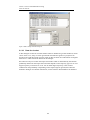
1
AVAL 6.6 User’s Manual Indirect Firing AVAL 6.6 User’s Manual Indirect Firing January 2008 All rights reserved Swedish Defence Research Agency (FOI, Sweden) www.foi.se/aval [email protected] 1 AVAL 6.6 User’s Manual Indirect Firing www.foi.se/aval 2 Table of Contents 1 Definitions 5 1.1 Coordinate systems ..........................................................................5 1.2 File structure .....................................................................................6 2 2.1 2.1.1 2.1.2 2.1.3 2.1.4 2.1.5 2.1.6 2.1.7 2.1.8 2.1.9 2.1.10 2.2 3 Defining a Weapon platform 7 Ballistic data ......................................................................................9 Projectile data .............................................................................10 Aerodynamic data .......................................................................11 End phase data...........................................................................12 Thrust data..................................................................................14 Basebleed data ...........................................................................14 Separation data...........................................................................14 Canister data...............................................................................15 Sub shell data .............................................................................16 Data for settings calculations......................................................17 Data for ricochet..........................................................................18 Firing sequence...............................................................................19 Building an indirect fire scene 21 3.1 Define Map......................................................................................21 3.2 Define scene title.............................................................................21 3.3 Insert target .....................................................................................21 3.3.1 Transformation data for alternative target position .....................24 3.4 Create target path ...........................................................................26 3.5 Define fault tree...............................................................................26 3.6 Insert weapon platform ...................................................................27 3.7 Insert observer ................................................................................29 3.7.1 3.7.2 Relative observer position ..........................................................29 From map....................................................................................30 3.8 Environment protection ...................................................................31 3.9 File format for indirect fire scene.....................................................31 4 Ballistic simulation 32 4.1 Trajectory calculations ....................................................................32 4.2 Settings calculation for a weapon platform .....................................36 5 5.1 Indirect fire simulation 38 Simulation settings ..........................................................................38 3 AVAL 6.6 User’s Manual Indirect Firing www.foi.se/aval 5.2 Specify method for calculating fragment hits on target .................. 40 5.3 Calculation scheme during the simulation...................................... 41 5.4 Result presentation ........................................................................ 42 5.4.1 5.4.2 Graphics ..................................................................................... 42 Output files ................................................................................. 44 4 1 Definitions An indirect fire scene is defined in an environment described by a map, height data and environment protection. These input data are common for indirect fire simulation and minefield simulation and therefore they are described in a separate document User’s Manual MAPS. In addition to the environment an indirect fire scene will consist of following objects described in this document. • • • • • Targets Target paths Weapon platforms Observer Scene fault tree 1.1 Coordinate systems AVAL assumes all coordinates to be given in the 2,5gon V 1990 coordinate system, also named RT90, in plane and RH 70 in height. In these systems the x-axis is from south to north, y-axis is from west to east and heights are positive above a defined zero plane (sea level). The ballistic calculations are performed in a right-handed coordinate system with the x-axis headed north and z-axis headed downwards. Consequently all heights from the database are converted to negative z-values. Note the difference between heights, positive upwards, and zvalues positive downwards. Directions are defined with their bearing, measured clockwise from the x-axis (north). xp X-coordinate for the target position in the scene. yp Y-coordinate for the target position in the scene. vt Target velocity. Bearing Target traveling direction. Given clockwise relative north axis. All targets in the scene are assumed to be ground targets and they are vertically translated to locate the smallest z-value (in the local coordinate system) on the ground. If the ground is broken the elevation and roll angle of the target is automatically adjusted to the ground slope, with respect to the target bearing, for every new position of the target. Figure 1 Coordinate system. 5 AVAL 6.6 User’s Manual Indirect Firing www.foi.se/aval 1.2 File structure Input files File File type Included file references *.mls Indirect fire simulation file *.mpc *.atm (for simulation) *.mpc Indirect fire scene *.* (height data base) *.evp *.trg *.wpi *.syc *.* Height data base. Extension depending on provider. See User’s Manual MAPS *.evp Environment protection. See User’s Manual MAPS *.atm Atmosphere *.trg Complete AVAL target description See AVAL Target description manual *.wpi Indirect fire weapon description *.bal *.fsq *.atm (for settings calc.) *.syc Scene fault tree *.ftr *.ftr Translation file for target top events into scene events *.bal Ballistic data *.fsq Firing sequence for weapon *.wcf Complete AVAL warhead carrier description *.wcf 6 See AVAL User’s Manual 2 Defining a Weapon platform Start the AVAL program and choose Modes -> Indirect fire map from the top menu. A weapon platform is defined by selecting Weapon->Weapon from the menu, which will open a dialog to define data for the weapon platform description: Figure 2 Weapon platform for indirect fire dialog box. Filename for weapon platform Open an existing or create a new file via the Open button. Title for weapon platform Title for the weapon platform. File containing data for firing sequence. Path and name of a predefined file containing the firing sequence. File containing data for ballistic settings calculation. Path and name of a predefined file containing ballistic data. If a cargo shell is used only one canister and one sub shell shall be defined. Data shall correspond to mean values for all canisters and sub shells. File containing data for ballistic Monte-Carlo simulations and warhead carrier. Path and name of a predefined file containing ballistic data and warhead carrier. This file shall contain all canisters and sub shells and actual standard deviations. Start distance for sensor activation The distance from the ground or a target where the ballistic calculation shall be interrupted and the fuze system of the warhead carrier shall be activated. 7 AVAL 6.6 User’s Manual Indirect Firing www.foi.se/aval From this point the warhead carrier is assumed to have a straight travel with the direction and velocity calculated in the last time step of the ballistic calculation. If the fuze system contains an artillery fuze the given distance is the distance above the highest altitude where the fuze is able trig the warhead. Deviation for settings The standard deviation for elevation and bearing when fires the weapon. Calculated settings will be randomized based on these deviations to get the actual elevation and bearing of the weapon when fired. Deviation for position Standard deviation and accuracy for the weapon platform position. The nominal position is defined when inserting the weapon into the scene and that position will be randomized based on these deviations to define its assumed position. From this assumed position the weapon settings are calculated. Simulation options settings calculations Simulation options for calculating weapon settings. Figure 3 Simulations options for settings calculations dialog box. Atmosphere A path and name of the atmosphere data file to be used for the settings calculation is defined. Deviation Depending on the given ballistic data either the standard deviation for powder temperature or muzzle velocity is given. Trajectory method Depending on given ballistic data there are up to three alternative calculation methods to select from: mass point method, NATO’s modified mass point method and six degrees of freedom. Trajectory method canister phase 8 This option is enabled if the ballistic data contains a canister phase. Trajectory method separation This option is enabled if the ballistic data contains separation data. Simulation options Monte Carlo simulation. Contains the same options as Simulation options settings calculations except for the atmosphere, which is omitted here. The atmosphere for Monte Carlo simulations is defined when defining the simulation. 2.1 Ballistic data The ballistic description of a shell used in a weapon platform can be either a conventional shell or a cargo shell. The ballistic data for the cargo shell must be complemented with ballistic data for the sub shells and optional ballistic data for the canister phase of cargo shell. The dialog box for ballistic data is opened from the menu via Weapon->Ballistics. The ballistic calculation is described in Reference Manual Ballistics Figure 4 Ballistic and warhead carrier data dialog box. The ballistic description can be one of the following types: • • • Conventional shell for indirect fire Cargo shell for indirect fire Sub shell used in cargo shell 9 AVAL 6.6 User’s Manual Indirect Firing www.foi.se/aval • Shell for canister phase The check box named: Define data for end phase shall be checked if the trajectory end phase data shall be defined for indirect firing shells. 2.1.1 Projectile data This dialogue contains the following data. Figure 5: Projectile data dialog box. Charge data… Charge data contains mean value and standard deviation for muzzle velocity for all charges. No temperature dependence are used. Charge data (Temperature dep.)… Charge data contains mean value and standard deviation for muzzle velocity for all charges, when temperature dependence is used. The dialogue has the following layout. Figure 6 Charge data (temperature dependent) dialog box. 10 2.1.2 Aerodynamic data Aerodynamic coefficients are defined in this dialogue. The method where each coefficient is used is defined in the list below (within parenthesis). 1. 2. Air drag CD. Can only vary with Mach number (Point mass, NATO, 6DOF) Induced air drag CDa2. (NATO, 6DOF) Varies with Mach number and angle of attack. Derivative can be defined which varies with Mach number. 3. Normal force coefficient CN. (NATO, 6DOF) Varies with Mach number and angle of attack Derivative can be defined which varies with Mach number. 4. (NATO, 6DOF) Moment coefficient CM. Varies with Mach number and angle of attack Derivative can be defined which varies with Mach number. Position for CN can be defined as a function of Mach number and angle of attack. 5. Damp moment coefficient CMQ (6DOF) Varies with Mach number and angle of attack. 6. (NATO) Magnus force coefficient CNp Varies with Mach number and angle of attack. Derivative can be defined which varies with Mach number. 7. Magnus moment coefficient CMp (6DOF) Varies with Mach number and angle of attack. Derivative can be defined which varies with Mach number. Position for CMp can be defined as a function of Mach number and angle of attack. 8. Spin damp moment coefficient Clp. (NATO, 6DOF) Can only vary with Mach number 9. Spin moment coefficient Cl. (6DOF) Can only vary with Mach number 10. Normal force coefficient for rudder Cy y-component. (6DOF) Can only vary with Mach number 11. Normal force coefficient for rudder Cz z-component. (6DOF) Can only vary with Mach number 12. Moment coefficient for rudder Cmy y-component. Can only vary with Mach number 11 (6DOF) AVAL 6.6 User’s Manual Indirect Firing www.foi.se/aval 13. Derivative for normal force coefficient used for twisted fins. (NATO, 6DOF) Can only vary with Mach number Notify that the normal force coefficient is defined instead of the lift coefficient which NATO:s modified mass point model are using. The program calculates the lift coefficient Cl from the normal force coefficient Cn. Figure 7 Aerodynamic data dialog. 2.1.3 End phase data The dialogue has the following layout: 12 Figure 8 End phase data dialog box. If the shell does not separate in trajectory the following data must be defined for each charge as a function of distance (considering a flat ground: • • • • • • • Di Vi ti θi pi σLi σSi Distance to impact position. Velocity at impact position. Flight time to impact position. Elevation at impact position. Rotation velocity at impact position. Standard deviation in length for defined distances. Standard deviation in side for defined distances. Data are possible to define for both under and over degree trajectories. An under degree trajectory is a trajectory with a distance smaller than max range (DMax) and an elevation smaller than the elevation causing max distance (EDMax). Elevation for under degree trajectories 0<E<EDMax Elevation for over degree trajectories EDMax <E<0.5*π If separation takes place the given data shall correspond to the separation point in trajectory. The program automatically calculates the separation height over ground by iterations. The separation height is determined from nominal flight time for canister and sub shell and their ballistic data, which are necessary for both canister and sub shells. 13 AVAL 6.6 User’s Manual Indirect Firing www.foi.se/aval 2.1.4 Thrust data The following variables are defined as time dependent input data for rockets: • • • • • Pull force Projectile mass Position of the projectile centre of gravity Axial moment of inertia for the projectile Transverse moment of inertia for the projectile 2.1.5 T(t) m(t) xcg(t) Ix(t) y,z(t) Basebleed data The following variables are defined a base bleed: Figure 9 Basebleed data dialog box. Base drag, mass flow and rotation factor dependence are defined in additional dialogues. 2.1.6 Separation data Standard deviations for cargo separation time together with limitations for separation are defined in this dialogue. Limitations are min and max rotation velocity for different separation velocities. 14 Figure 10 Separation data dialog box. 2.1.7 Canister data Each canister might have separate data. Following data are defined for each canister: • • • • A file defined containing the ballistic input data. Change in axial velocity at separation point. Mean and standard deviation for flight time. Standard deviations for bearing and elevation disturbances at separation point. Figure 11 Data for all canister shells dialog box. 15 AVAL 6.6 User’s Manual Indirect Firing www.foi.se/aval 2.1.8 Sub shell data Three times are defined: Ts The nominal flight time for sub shell. This is used for determining the separation point. Tsa Time until sub shell is armed. If the sub shell hits ground before this time it wont function adequate. Tsd Time until auto destruction. If the sub shell contain a scanning infrared sensor the height Hs is the distance over ground where scanning on target area normally starts. This data together with the nominal flight time is used by the fire element calculator to determine the separation point. Sub shells are located in layers. The projectile in Figure 12 below has three layers and four sub shells in layer number 1. Figure 12 Subshell description. The following data are common for each layer: tdi Time delay until separation for layer number i. This time delay is measured from the time when separation first started. vai Axial separation velocity for sub shells in layer number i. σsri Standard deviation in radial direction for sub shells in layer number i. The nominal direction is calculated from (y,z)-coordinate for sub shell position. A layer can contain an arbitrary number of sub shells. For each sub shell in a layer the (x,y,z)coordinates for position must always be defined. This position is used for determining nominal radial direction and in some cases even radial velocity. The following data is defined for each sub shell in a layer: xsij x-coordinate for sub shell number j i layer number i. ysij y-coordinate for sub shell number j i layer number i. zsij z-coordinate for sub shell number j i layer number i. 16 vrmij The mean value for radial velocity is optional. vrdij The standard deviation for radial velocity is optional. The dialogue has the following layout: Figure 13 Data for subshells dialog box. 2.1.9 Data for settings calculations In this dialogue are limitations for elevations defined for each charge. The data for all charges are displayed in the first section of the dialogue. 17 AVAL 6.6 User’s Manual Indirect Firing www.foi.se/aval Figure 14 Data for settings calculation dialog box. 2.1.10 Data for ricochet In this dialogue are data for ricochet defined. Data are defined for ground conditions, which can be water or ice, stony or frozen ground and miscellaneous ground. A projectile can deviate to the right due to high spin rate. Data for this deviation are randomized rectangular between two values which are defined in the dialogue. Ricochet will only occur when the impact fuze failure which is determined by the function probability defined for the impact fuze. Ricochet depends on the trajectory type. For an over degree trajectory ricochet never occur. For an under degree trajectory is the ricochet randomized. The probability is depending on the impact angle on ground, these data are defined in dialogue. For further information, see the reference documentation for ballistics. 18 Figure 15 Data for ricochet dialog box. 2.2 Firing sequence The weapon platform contains a path and name of a file with the weapon firing sequence. A firing sequence is defined in a dialog box opened via Weapon->Firing sequence in the menu. Figure 16 Define firing sequence dialog box. 19 AVAL 6.6 User’s Manual Indirect Firing www.foi.se/aval Filename Click Open file… to open an existing file or create a new firing sequence file. Number of barrels A weapon can be described with one or two barrels. The selection of one or two barrels will have effect on the optimized firing times for MRSI. Number of rounds Total number of rounds that the weapon can fire. Min time delay between rounds The minimum time needed between each round in the firing sequence. Next round in the sequence cannot be fired until the delay time for the round has elapsed. MRSI The firing time will be calculated with the intention of simultaneous impact for all fired rounds. No round will have less delay time than the minimum delay time set for the round. Use defined time delay The rounds will be fired with exactly the given delay time between each round. A preference for selected charges is also possible with this alternative. Prefer OD trajectory and select a middle charge (preference). Calculated settings and gun loads causing an over degree trajectory will be preferred before loads and settings causing under degree trajectories for current firing distance. Elevation will be greater than the elevation calculated for max firing distance. A charge in the middle of possible charges will be selected. Prefer UD trajectory and select a middle charge (preference) Calculated settings and gun loads causing an overdegree trajectory will be preferred before loads and settings causing underdegree trajectories for current firing distance. Elevation will be greater than the elevation calculated for max firing distance. A charge in the middle of possible charges will be selected. Prefer UD trajectory and lowest possible charge (preference) Calculated settings and gun loads causing an overdegree trajectory will be preferred before loads and settings causing underdegree trajectories for current firing distance. Elevation will be greater than the elevation calculated for max firing distance. The lowest of possible charges will be selected. 20 3 Building an indirect fire scene A complete scene can be read from file or built in AVAL and saved to file. All commands to build a scene are found in the Indirect fire map menu under Scene. Figure 17 AVAL / Indirect fire mode / Scene. The Indirect fire scene is built with following commands and preferable in given order: • • • • • • • • Define Map Define scene title Insert target Create target path Define fault tree Insert weapon platform Insert observer Environment protection 3.1 Define Map This command loads a bitmap image as map, a map data file with position (coordinates) and resolution (meters/pixel) for the map and a file with map symbols. A simplified terrain map will be loaded, or created if it does not exist, automatically. The map is common for Indirect fire mode and Minefield mode and therefore described in User’s Manual MAPS. Height data is optional and if omitted all heights are assumed to be 0.0. 3.2 Define scene title Give the scene a descriptive name for administration purposes. 3.3 Insert target When this command is selected a target symbol will be added to mouse pointer and the position of the target is defined by left clicking in the map. When the mouse button is released 21 AVAL 6.6 User’s Manual Indirect Firing www.foi.se/aval a dialog box will be opened to define data for the target. After inserting a target its data can be edited by choosing Map tools → Edit object in the menu and selecting the target by left clicking on the symbol which will open the same dialog box. Its position can be also changed by selecting Move object, left click on the symbol and drag it with the left mouse button down. Figure 18 Edit target dialog boxes. Associated AVAL target. The search path to a complete AVAL target description selected via the Open… button. The format of a target description is the same as used in single target simulations, with no exceptions. User description An informative description to identify this particular target. This description is drawn in the map and written to the scene file and result files. Unit symbol Opens a dialog box for selecting symbol to use in the map for the target. 22 Figure 19 Unit symbol dialog box. The available symbols are those defined in the *.sym file which is read when loading the map. The symbol size is in pixels and will be constant for any zoom scale. Ground target If checked the target height position will be that of the ground at current xand y-position. The elevation and roll angle of the target will also be automatically calculated with respect to the ground slope and target bearing. If not checked the given height, elevation and bearing will be used. Target path Selecting a predefined path will force the target to follow this path with given velocity. If the start position of the path and the position of the target do not coincide the start point of the path will be moved to the target position. If the target position is altered later, by mouse or via the dialog box, the start point of the connected path will follow the target position. A path can only be coupled to one target. If a target path is not coupled when the targets are inserted, this can be done afterwards by editing the targets. Velocity The velocity is the velocity of the target in a path or in the bearing of the target. In case an alternative position of the target is selected the velocity is set to 0. Reaction time to start The target will start moving with defined velocity (in target direction or along a path if defined) or is transformed to an alternative position if defined when the first warhead detonates, delayed with the defined reaction time of the target. Alternative position The target components are transformed according to defined transformation file at defined reaction time from the first warhead detonation in the scene. For example can a standing soldier be transformed into a laying position. (See 5.3.1 for file format etc.) 23 AVAL 6.6 User’s Manual Indirect Firing www.foi.se/aval 3.3.1 Transformation data for alternative target position Transformation data can be calculated, saved, read and used in single target mode, on currently loaded target, via Component->Alternative position in the single target menu. Figure 20 Calculate alternative position menu option. Calculate Select a new alternative target with the same component content as the original loaded target. Transformation data will be calculated for each component used in the target. If components in the original target are not found in the alternative target, searched by number and type, no transformation data will be set. Occasionally calculations can result in wrong transformation data for some components in a target due to mismatched component geometry or singularity in the Euler transformation matrix. The calculated transformation data can be checked via Alternative position -> Set in the menu. Save Saves the calculated, or read, transformation data to selected file. File extension .trf is assumed. Read Reads a predefined transformation data file. File extension .trf is assumed. Set Alternative Sets/Resets the target components by calculated or read transformation data. Hit points and created holes are included in the transformation. 24 Figure 21 Example of a target transformed via a transformation data file. Transformation file format: First row in the file is the title of the original target which must match the original target title. Then follows one row for each component to transform containing: • • • • • • • • Component type, 0= vital, 1=structure (ERA and LRA is not yet implemented) Component number. Rotation about the z-axis, psi. Rotation about the y-axis, theta. Rotation about the x-axis, phi. Displacement in x direction. Displacement in y direction. Displacement in z direction. Example of a transformation data file: Figure 22: Example of a transformation file. 25 AVAL 6.6 User’s Manual Indirect Firing www.foi.se/aval 3.4 Create target path Use the menu command Create a target path. The path is then defined by clicking each start, break and end point of the path in the map. After clicking the end point, a click on Esc or Enter stops the input session. The paths are automatically named Path nr X with increasing numbers. It is now possible to rename, edit or remove the created path by selecting Edit object under Map tools in the menu and left click on the created path in the map. This will open a dialog box with the path data and options to rename, edit or remove points or the whole path. Figure 23 Edit target path dialog box. If the target path is not coupled to a target, the target can now be edited by selecting Edit object under Map tools in the menu and left click on the target in the map. The path is chosen in the list. 3.5 Define fault tree Clicking “Define faulttree…” in the menu opens a dialog box where you shall select a predefined scene fault tree file (.syc). Each target inserted in the scene has a fault tree with one or more top events. These top events are used as events in the scene fault tree. The scene fault tree has the same format as the target fault tree but shall include a file path to a translation file. A translation file must be manually created to connect target top events to scene events. In the translation file selected top events in each target are given unique scene event numbers and these scene events are used in the scene fault tree in the same way as component numbers are used in a target fault tree. 26 Example of a translation file used in a scene fault tree: !Scene event 5001 5002 5003 5004 5005 Target number 1 2 3 4 5 Target event 3017 3017 3017 3017 3017 In the example above four targets of the same kind are inserted in the scene. Only the top event 3017 for each target, are used in the scene fault tree. If top event number 3017 of target number 2 occurs in the simulation this will be represented as if scene event 5002 has occurred in the scene fault tree. Scene event 5002 represents in turn the sub event 4002 in the fault tree, which is used in the top event definitions. Example of a scene fault tree with scene events from the translation file above: 2 ! Fault tree type: 2=Scene 5001 5005 'C:\A66\Calc\IF\Scene\Demo\Transl.ftr' ! Min and Max scene event number, file path 4001 4005 ! Sub events, min and max numbers 7001 7005 ! Top events, min and max numbers ! ! Sub events * 4001 'AFV 1 disabled' L 1 5001 * 4002 'AFV 2 disabled' L 1 5002 * 4003 'AFV 3 disabled' L 1 5003 * 4004 'AFV 4 disabled' L 1 5004 * 4005 'AFV 5 disabled' L 1 5005 ! Top events * 7001 'Least 1 AFV disabled L 1 4001 4002 4003 4004 4005 * 7002 'Least 2 AFVs disabled' L 2 4001 4002 4003 4004 4005 * 7003 'Least 3 AFVs disabled' L 3 4001 4002 4003 4004 4005 * 7004 'Least 4 AFVs disabled' L 4 4001 4002 4003 4004 4005 * 7005 'Least 5 AFVs disabled' L 5 4001 4002 4003 4004 4005 3.6 Insert weapon platform A symbol for the weapon will follow the mouse cursor and its position is defined by clicking in the map. When the mouse button is released a dialog box will be opened for adding data to the weapon platform. These values can be edited afterwards by selecting Map tools → Edit object in the menu and click on the weapon symbol which will open the same dialog. 27 AVAL 6.6 User’s Manual Indirect Firing www.foi.se/aval Figure 24 Edit weapon dialog box. Associated indirect fire weapon Search path to a file with a complete description of an indirect fire weapon (*.wpi). User description An informative description to identify this particular target. This description is drawn in the map and written to the scene file and result files. Unit symbol Opens a dialog box for selecting symbol to use in the map for the target. This dialog and optional symbols are the as for targets. See chapter 3.3 Insert target Position The nominal position of the weapon platform. Can be altered in the dialog box or changed by dragging the weapon symbol in the map. Position The nominal aim point for the weapon platform. Can be altered in the dialog box or changed by dragging the aim point symbol in the map. Adjusted hit point for each round relative nominal aim point. If the weapon platform is defined with a firing sequence including more than one round then each round can be adjusted in length or side relative the given nominal aim point. The adjustment for each round is defined by selecting the round in the combo box and set its adjustment in the text boxes to the right. The adjustment is given positive if the aim point of the round is beyond the nominal aim point and positive if the round aim point is to the right of nominal aim point. 28 If no adjustment is given for a round the nominal aim point is used for that round. The ballistic calculation for weapon settings, bearing and elevation, is performed for the nominal aim point and a point 10 m beyond it. The adjusted elevation for each round will be interpolated / extrapolated from these two settings. The bearing will be adjusted geometrically with respect to side leeway due to gun twist. Figure 25 Example showing separate round aim points. If the option Map tools -> Show separate round aim points is activated each aim point can be moved by dragging the aim point symbol with left mouse button down. If the nominal aim point is moved in the map the round aim points will follow the nominal aim point with their relative adjustment intact. 3.7 Insert observer If an observer is added to the scene the fault from the observers surveillance of the target position is added to the nominal aim point for each weapon platform inserted to scene. The observer is inserted into the scene by putting the symbol in the map with the left mouse button. When the button is released a dialog box is opened to set data for the observer. After inserting an observer its data can be edited by choosing Map tools → Edit object under in the menu and selecting the observer by left clicking on the symbol and this will open the same dialog box. Its position can also be changed by selecting Move object, left click on the symbol and drag it with the left mouse button down. Only one observer can be added to a scene. The observer can be set to survey the target in one of two ways, relative his own position by measuring the distance and bearing to the target or by reading the target position from a map. 3.7.1 Relative observer position In this mode the observer nominal position is used and the standard deviation and accuracy of his position is given. The deviation for target surveying is also given with standard deviation and accuracy for distance and bearing to the target separately. In order to calculate the faults given from bearing deviation the surveying point must be given, which consequently should be near the center of the observed targets. 29 AVAL 6.6 User’s Manual Indirect Firing www.foi.se/aval Figure 26 Observer settings dialog box. Measurements relative observer position. 3.7.2 From map In this mode the observer position and nominal aim point (surveying point) is not used and therefore greyed out in the dialog box. The deviation for the observer is given with standard deviation and accuracy for the observer reported x- and y-position of the target. Figure 27 Observer settings dialog box. Measurements from map. 30 3.8 Environment protection Opens dialog to define environment protection or load a predefined environment protection file. The environment protection file is optional and if omitted no protection will be considered from the environment. Environment protection, from ground objects, can be roughly described for different ground categories and is used to reduce penetration capacity for fragmenting warheads. Each terrain type in the map can be connected with a protection type defined in an environment protection file (*.evp). Several terrain types can have the same protection type. The environment protection file is common for Indirect fire mode and Minefield mode and therefore described in User’s Manual MAPS. 3.9 File format for indirect fire scene When the scene is created it can be saved to file via Scene -> Save or Save as.. and a saved scene can be saved via Scene -> Read minefield scene. Example of an indirect fire scene file: Figure 28 Example of indirect fire scene file. 31 AVAL 6.6 User’s Manual Indirect Firing www.foi.se/aval 4 Ballistic simulation Ballistic simulation can be performed for either a single shell to find settings, range and trajectory or for a weapon platform to find possible gun charges and settings for all rounds in its firing sequence. For the ballistic calculation please refer to Reference Manual for Ballistics. 4.1 Trajectory calculations Ballistic calculations for a single shell is started via Ballistics->Trajectory in the menu. Figure 29 Trajectory calculation dialog box. Open file... To open a file with predefined ballistic data. Calculation options… Selection of ballistic calculation method and earth approximation. Figure 30 Settings for trajectory dialog box. Stop conditions… A stop condition must be selected for the ballistic calculation. 32 Figure 31 Stop conditions dialog box. If the ballistic data contains a cargo shell with sub shells the stop condition must be set for the sub shells as well. Set initial velocity… Opens a dialog with charges defined in the ballistic data. Figure 32 Initial velocity dialog box. Select atmosphere… An atmosphere must be defined to be used in the calculation. 33 AVAL 6.6 User’s Manual Indirect Firing www.foi.se/aval Figure 33 Atmosphere dialog box. In the dialog a new atmosphere can be defined or a predefined atmosphere can be read from file. Write plotfile Optional the calculations can be saved to a plotfile with a defined time step. Calculate trajectory… To calculate a single shell trajectory for defined V0, elevation, bearing, start points and projectile mass. The calculation results are given in the dialog and saved to file if the Write plot file option is checked. 34 Figure 34 Single trajectory dialog box. Calculate settings… To calculate settings for defined range, bearing to hit point, V0, start point and projectile mass. Figure 35 Find settings dialog box. 35 AVAL 6.6 User’s Manual Indirect Firing www.foi.se/aval Calculate Dmax… Calculate settings for and max firing range with defined V0, start point and projectile mass. Figure 36 Calculate Dmax dialog box. 4.2 Settings calculation for a weapon platform This is an option to calculate and view all possible charges, and the settings for each charge, for a given firing range. The simulation also calculates a preferred set of charges for all rounds described in the firing sequence of the weapon platform. This is the calculation performed in a direct fire simulation to define settings for a weapon platform. The atmosphere defined in the weapon platform is used in the settings calculations and the atmosphere defined in the direct fire simulation is used to calculate the ballistic trajectory in the indirect fire simulation. The dialog box is opened via Ballistics->Calculate settings... in the menu. 36 Figure 37 Calculate settings for indirect firing dialog box. Open file… To open a file with a predefined weapon platform. Possible settings for all charges Table with calculated settings for each gun charge described in the weapon platform. For each charge elevation, bearing and flight time for both underdegree and overdegree trajectory are calculated. If a charge is not possible to use for either under or over degree trajectory at given range the result is given as Undefined in the table. Settings for all rounds Table with selected charges and firing times for each round described in the firing sequence of the weapon platform. If simultaneous impact, MRSI, is chosen for the weapon the firing time is calculated, otherwise the defined min time between rounds is used. 37 AVAL 6.6 User’s Manual Indirect Firing www.foi.se/aval 5 Indirect fire simulation 5.1 Simulation settings Start the AVAL program and choose Modes -> Indirect fire map from the top menu. An indirect fire simulation is started via MC simulation->Lethality simulation in the menu. Figure 38 Lethality simulation indirect fire dialog box. Simulation file: Create a new file to save simulation settings or open an existing file with predefined simulation settings. Simulation title: Descriptive name of the simulation for administrative purpose. Indirect fire scene: Path and name of the indirect fire scene to simulate. If a new simulation is created the current scene in the indirect fire window will be used. If a predefined simulation file is 38 opened the scene given in that simulation file will be loaded into the current window. Atmosphere for simulation: Path and name of the atmosphere to be used in the simulation. The atmosphere given in the weapon platform will be used for the settings calculation. Single weapon simulation: Possibility to perform a simulation with one weapon platform in the scene at a time. Simulations with a single weapon is bounded to one Monte Carlo cycle. Calculate warhead effect: If not checked only burst points will be calculated. If checked simulations with all warhead effects against the targets in the scene will be performed after each burst point. Since warhead effects in a shell are calculated directly after the burst point a different random series will be created when calculating effects compared to when not. This will consequently result in different burst point patterns when calculation of warhead effects are included or not. The reason to calculate warhead effects direct after the burst point is that the shells will detonate separately in time. If a moving target is hit by one round its mobility may be disabled and it will therefore not be in the same position as if not hit when the next round is approaching. To work around this a previous calculated burst point file can be used in the simulation. Use defined burst points: For each simulation performed a burst point file is created and its full path is saved in the simulation file. If a simulation is previously performed and this alternative is checked the current simulation will skip the burst point calculation and use the file in the simulation file. It is possible to change this file path in the simulation file using a text editor before loading the simulation file if another burst point file but the last is wanted. Initialize: Before the simulation can start all targets, weapons etc. used in the scene must be read. Simulation settings: Opens dialog to select all possible phenomena to be calculated in the simulation. Simulation settings are made for each target in the scene. This button is disabled until the scene is initialized. Select presentation variable: Used to select a scene top event and time to view in the dialog while running the simulation. The result for the selected event is updated in the dialog in the Mean value and Confidence interval text boxes for each Monte Carlo cycle. 39 AVAL 6.6 User’s Manual Indirect Firing www.foi.se/aval 5.2 Specify method for calculating fragment hits on target If a warhead effect containing fragment data is selected options are available for calculating fragment hits on target. Click on the button Options for fragment hit calc..., and then the following dialog box is opened. Figure 39 Options for fragment calculations dialog box. In this mode are three options possible: Standard means that all fragments which approach the target are calculated. If the burst point is situated inside a sphere containing all target geometry all fragments are calculated until the leave the sphere or hits the target. If a ground is defined all fragments which approach the ground polygons also are calculated. If the radio button named optimized is selected a more sophisticated selection method is used. A fragment which direction has a bearing which is between the bearings for target limitations (βmin, βmax) is selected, see Figure 40 below. The elevation angle for the fragment direction must be greater than the min elevation angle (θmin) in Figure 40 below. The ground is not considered at all with this method. 40 Figure 40 Definition of fragment ejection angles used for optimized fragment calculations. 5.3 Calculation scheme during the simulation When a simulation is started the calculations will be performed according to the following scheme: For each Monte Carlo cycle: • Randomize observer surveying faults. • For each weapon in the scene: o Adjust aim point with observer faults o Adjust weapon position with randomized weapon surveying faults o Calculate weapon settings and firing time for each round. • Sort all rounds from all weapons firing time • For each round, sorted by firing time: o Adjust calculated setting with weapon deviation. o Perform ballistic calculation using the adjusted settings and the weapon nominal position. The ballistic calculation breaks at given distance for sensor activation from the ground, height over ground for artillery fuzes, or a target. o For conventional shells: Calculate burst point using the warhead carrier of the weapon with direction and velocity from the last ballistic iteration step. Burst points are calculated on all targets, if hit, and the ground and the burst point with shortest burst time is used. If Calculate warhead effects is checked and the warhead detonates warhead effects are calculated in the scene using the 41 AVAL 6.6 User’s Manual Indirect Firing www.foi.se/aval calculated burst point. All targets in the scene are included with their position and velocity at calculated burst time. o For cargo shells: Calculate separation data. Perform ballistic calculation using the calculated separation data for each sub shell. The ballistic calculation breaks at given distance for sensor activation from the ground, height over ground for artillery fuzes, or a target. Calculate burst point using the warhead carrier of the sub shell with direction and velocity from the last ballistic iteration step. Burst points are calculated on all targets and the ground and the burst point with shortest burst time is used. If Calculate warhead effects is checked and the warhead detonates calculate effects in the scene with the calculated burst point. All targets in the scene are included with their position and velocity at calculated burst time. Figure 41 Possible faults included in the simulations. 5.4 Result presentation 5.4.1 Graphics The following simulation results are presented in the map window or a target window: Burst points 42 All burst points are always drawn in the map. In order to reduce the calculation time all burst points are drawn after the last Monte Carlo cycle. The number of burst points shown is maximized to 32768 due to limitations in the map. Additional burst points are used but not drawn in the map. Figure 42 Example of ploted burst points. Hits by Warhead effects on the ground. Only drawn if the simulation is performed for one single Monte Carlo cycle and Calculate warhead effect is checked. Warhead effects that hit a target or that loose all their velocity due to environment protection will not be drawn in the map. Figure 43 Example of hits by warhead effects on the ground. Warhead hits on targets Warhead hits on targets are only updated if the simulation is performed for one single Monte Carlo cycle and Calculate warhead effect is checked. Each target in the scene can be viewed in a single target window. The dialog to select targets is opened in the indirect fire menu via Scene->View target. 43 AVAL 6.6 User’s Manual Indirect Firing www.foi.se/aval Figure 44 View target in map dialog box. Figure 45 Example of warhead effect hits on target. 5.4.2 Output files An indirect fire simulation will produce a result text file, a burst point file and an effect file. 5.4.2.1 Result text file The result text file will get the name SimFileN.txt where SimFile is the name of the simulation file, without file extension, and N is an increasing numbering of consecutively produced result files using the same simulation file. The text file includes the following information: • • • • • Simulation date and time Simulation settings for each target in the scene Number of MC-cycles and detailed result of each cycle run Evaluation time and outcome of the scene fault tree For each target a section is given with: o Target name and its start position in scene o Number of hits on each target. Hits by warhead carrier are increased when the target have trigged the fuze. Hits by warhead effect are increased for each hit by a fragment, shaped charge etc. In the example file below a shaped charge with impact fuze causes these to be equal. o The outcome of the target fault tree • A section with other result files and calculation times. 44 5.4.2.2 Effect file The effect file will get the name SimFileEffectN.skv where SimFile is the name of the simulation file without file extension and N is an increasing numbering of consecutively produced result files using the same simulation file. The effect file includes the outcome of the top events in the scene fault tree for each evaluation time and each Monte Carlo cycle. 5.4.2.3 Burst point file The burst point file will get the name SimFileBurtsPointN.skv where SimFile is the name of the simulation file without file extension and N is an increasing numbering of consecutively produced result files using the same simulation file. The burst point file contains the following data for each round fired in the simulation: Cycle Monte Carlo cycle Gun Weapon platform firing the round Shot Round number for firing weapon Sub Subshell number if cargo shell, 0 if conventional shell Warhead Warhead identification HitType 0=Miss, 1=Impact, 2=Fuze TandemFlag 0=No tandem, 1=Tandem BurstTime RollAngle Warhead carrier roll angle at burst time RollRate Rotation velocity X Shell position at burst time Y Z DirX Shell direction at burst time DirY DirZ VelX Shell velocity at burst time VelY VelZ VelTarget Absolute velocity of target trigging the fuze, 0.0 if trigging on ground, height or time. 45 _________________________________________________________________________________________ FOI Swedish Defence Research Agency SE-164 90 Stockholm, Sweden Phone +46 (0)8 555 030 00 Fax +46 (0)8 555 031 00 www.foi.se