1
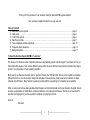
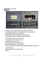
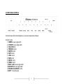
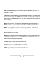
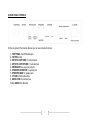
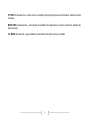
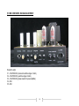
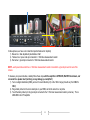
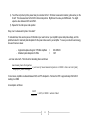
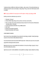
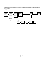
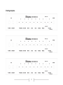
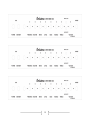
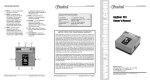
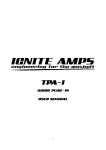
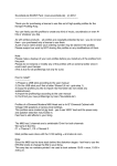
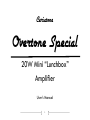
Ceriatone
Overtone Special
20W Mini “Lunchbox”
Amplifier
User’s Manual
1
Thank you for the purchase of your Ceriatone Overtone Special 20W Mini guitar amplifier!
Here, we hope to explain how best to use your new amp.
Table of Contents
1) About the Overtone Special…………………………………………………………………………………………page 2
2) Quick setup……………………………………………………………………………………………………………page 3
3) Front Panel controls………………………………………………………………………………………………….page 4
4) Rear Panel controls…………………………………………………………………………………………………..page 7
5) Tube compliment and bias adjustment……………………………….……………………………………………page 10
6) Frequently Asked Questions………………………………………………………………………………………...page 14
7) Settings templates…………………………………………………………………………………………………….page 17
1) About the Overtone Special 20W Mini “Lunchbox”
The release of our Overtone series of amplifiers has been overwhelmingly popular, and the support of customers such as you
has instigated the release of over a dozen different versions within the series. We have been pleased to provide many players
access to our unique take on these legendary amplifiers.
Most recently, we offered our first foray into the “lunchbox” format – the OTS Mini 20W. Not only is this amplifier a completely
different format for us, it is also a unique design that capitalizes on the expressive, sweet power section centered on classic
American-style 6V6 tubes. Many fantastic sounds are possible with this unassuming, but completely serious amplifier
While our work could not have been possible without the gracious information shared over the last decade in the public domain,
we hope you appreciate our modifications, component selection, and construction techniques. Most of all, we hope the OTS
becomes an integral part of your tone equation to exhilarate your playing and music.
Rock on!
Nik Azam
2
2) QUICK SETUP (for instant gratification)
1) Plug your guitar using a 1/4” instrument cable into the INPUT on the far right of the front panel
2) Plug a suitable power cable from the OTS’s rear panel MAINS cable inlet to your wall power receptacle
3) Plug the OTS into your speaker cabinet using 1/4” speaker cable
4) Set the IMPEDENCE selector to the match the impedance of your speaker cabinet
5) Plug the footswitch cable into the FOOT PEDAL jack on the rear panel of the amplifier
6) Set the OD TRIM control on the rear panel to 12:00 (clock face)
7) Set all rotary controls on the front panel to 12:00 (clock face)
8) Turn MASTER control to about 9:00 (clock face)
9) Set front panel MID BOOST switch in the down position (OFF)
10) Set front panel ROCK / JAZZ switch in the up position (ROCK)
11) Set front panel POWER switch in the upward ON position (with adjacent switch to STANDBY) for 30 seconds to allow
tube filaments to warm up
12) Set front panel STANDBY switch upward to the ON position
13) ROCK!!!!!!
3
3) FRONT PANEL CONTROLS
On the front panel of the Overtone Special, you can see fourteen items of interest.
From left to right:
1) POWER two-way toggle switch
2) STANDBY two-way toggle switch
3) INDICATOR LED
4) PRESENCE control
5) MASTER control
6) RATIO control
7) LEVEL control
8) BASS control
9) MIDDLE control
10) TREBLE control
11) ROCK / JAZZ two-way toggle switch
12) MID BOOST two-way toggle switch
13) VOLUME (PULL BRIGHT) control
14) INPUT ¼” instrument jack
4
POWER two-way toggle switch powers the OTS on and off. With the toggle switch in the UP position, the OTS is ON. In the
DOWN position, the OTS is OFF.
STANDBY applies high voltage to the vacuum tube anodes (and screen grids) during use of the OTS. To ensure long tube life,
first power the unit on with the toggle switch in STANDBY position for approximately 30 seconds. Then place switch upward to
ON position to use the OTS. With the toggle switch in the UP position, the OTS is in operate mode. In the DOWN position, the
OTS is in standby mode.
INDICATOR will illuminate when the OTS is powered by turning the rear panel MAINS toggle switch to the ON position. If
INDICATOR does not turn on, check your power cable connections, and then the 2A slow-blow fuse on the rear of the unit.
PRESENCE adjusts the high frequency response of the power amplifier using negative feedback. Use this control to add
sparkle and clarity to your tone.
MASTER sets the overall volume of your amplifier.
RATIO serves a sort of volume control for the overdrive channel. However, just like this version of the original amplifier, there
are not individual master volume controls for the clean and overdrive channels. Instead, the RATIO control serves to balance
out the volume of the overdrive channel with the clean channel.
LEVEL adjusts the amount of gain, and in turn distortion in the overdrive mode.
BASS adjusts low frequencies in your amplifier for both clean and overdrive modes.
MIDRANGE adjusts the mid frequency response for both clean and overdrive modes.
5
TREBLE adjusts the high frequency response for both clean and overdrive modes. At near-maximum settings, you may also
notice an increase in gain.
ROCK / JAZZ adjusts the overall frequency response and voicing of the amplifier. ROCK has a fatter midrange and a deeper,
spongier bottom end. You might find ROCK more familiar territory. JAZZ tightens up the bottom end and adjusts the contour of
the midrange, giving the amplifier more of a hi-fi response. Experiment with both, as great sounds rest in each. With the toggle
switch in the UP position, ROCK is on. In the DOWN position, JAZZ is on.
MID BOOST is a midrange-frequency boost. You can use this to add fatness to your clean or overdrive tones, or even make
single coil guitars sound thicker and less scooped. We particularly like MID BOOST with the overdrive mode. With the toggle
switch in the UP position, MID BOOST is on. In the DOWN position, MID BOOST is off.
VOLUME adjusts the signal strength coming out of the tonestack, and going into the second tube stage. Think of this as a gain
control primarily for your clean channel, but note it will impact the overdrive mode as well.
BRIGHT is a high-frequency boost that can be used to add sparkle to your tone in both clean and overdrive modes. This high
frequency boost is more prominent as VOLUME is turned down. To engage this feature, pull out the VOLUME control. To turn
BRIGHT off, push the VOLUME control inward.
INPUT jack provides a typical, 1megaohm input impedance as seen on most guitar amplifiers. The FET input has been
removed from the 20W Mini, as in most circumstances the regular input provides the best results in clean and overdrive modes.
6
4) REAR PANEL CONTROLS
On the rear panel of the Overtone Special, you can see ten items of interest.
1) FOOT PEDAL 5-pin DIN female jack
2) OD TRIM control
3) EFFECTS LOOP SEND ¼” instrument jack
4) EFFECTS LOOP RETURN ¼” instrument jack
5) IMPEDANCE three-way rotary selector
6) SPEAKERS EXTENTION ¼” speaker jack
7) SPEAKERS MAIN 1/4” speaker jack
8) HT FUSE 0.5A slow blow fuse
9) MAINS FUSE 2A slow blow fuse
10) A.C. MAINS IEC cable inlet
7
FOOT PEDAL 5-pin DIN female jack is used to connect the foot pedal to the amplifier. Use the foot pedal to control the
OVERDRIVE and PREAMP BOOST modes. Red LED indicates OVERDRIVE, and Green LED indicates PREAMP BOOST.
OD TRIM control. This control adjusts the signal strength sent to the first tube stable in the OVERDRIVE channel. Lower
settings yield more touch-sensitive, lower gain sounds. Higher settings are more compressed, higher gain, and more
harmonically complex. Start with the control between 10:00 and 12:00 (clock face), but experiment for your own ideal tone!
EFFECTS LOOP SEND ¼” instrument jack can be used to directly interface the preamp of the OTS, thereby bypassing the
power amplifier and using the OTS as a preamp. Conversely, this is usually used as the SEND of the effects loop. Plug the
input of your effects unit, or interface device (ex – C-lator, Klein-ulator) into this jack using ¼” instrument cable. The effects
loop in the OTS amplifiers are all passive, like the originals.
EFFECTS LOOP RETURN ¼” instrument jack can be used to directly interface the power amp of the OTS, thereby bypassing
the preamp and using the amplifier as a power amplifier. Conversely, this is usually used as the RETURN of the effects loop.
Plug the output of your effects unit, or interface device (ex – C-lator, Klein-ulator) into this jack using ¼” instrument cable. The
effects loop in the OTS amplifiers are all passive, like the originals.
IMPEDANCE three-way rotary selector. Set this selector to the position that matches the impedance of your speaker cabinet.
NOTE – if you are using two speaker cabinets in parallel (ex – two 16 Ohm cabinets), set the impedance selector to half that of
a single cabinet (in this case, 8 Ohms).
SPEAKERS EXTENSION AND MAIN ¼” speaker cable jacks. Use a ¼” speaker cable to connect your speaker cabinet to the
amplifier using these jacks. If you use one speaker cabinet, use the jack labeled MAIN. If you want to run two cabinets in
parallel, connect the second cabinet to the amplifier using the jack labeled EXTENSION.
NOTE – never turn your amplifier to OPERATE mode without connecting the amplifier to a speaker cabinet or suitable dummy
load! Failing to do so may damage your amplifier!
8
HT FUSE 0.5A slow-blow fuse – used to protect your amplifier, particularly during the event of tube failure. Replace only when
necessary.
MAINS FUSE 2A slow-blow fuse – used to protect your amplifier from voltage spikes or excessive current draw. Replace only
when necessary.
A.C. MAINS IEC cable inlet – plug a suitable IEC power cable into this inlet to power your amplifier
9
5) TUBE COMPLIMENT AND BIAS ADJUSTMENT
From left to right:
V1 – 12AX7/ECC83 (clean and overdrive stages 1 and 2)
V2 – 12AX7/ECC83 (overdrive stages 3 and 4)
V3 – 12AX7/ECC83 (phase inverter for power amplifier)
V4 – 6V6
V5 – 6V6
10
In these pictures, we have color coded the important features for simplicity
1) Blue arrow = bias adjustment potentiometer shaft
2) Yellow arrow = power tube pin connected to 1 Ohm bias measurement resistor
3) Red arrow = ground pin connected to 1 Ohm bias measurement resistor
NOTE – each power tube socket has a 1 Ohm bias measurement resistor connected to a ground pin near the rear of the
chassis.
To measure your power tube bias, carefully follow these steps with the amplifier in OPERATE, MASTER at minimum, and
connected to a speaker load (not doing so may damage your amplifier!):
1) Turn on a digital multimeter (DMM), and set it to read millivolts (mV) in the 100mV range (this will vary from DMM to
DMM)
2) Plug a black probe into the color-coded jack on your DMM, and do the same for a red probe
3) Touch the black probe tip to the ground pin connected to the 1 Ohm bias measurement resistor (red arrow). This is
GROUND in the OTS amplifier.
11
4) Touch the red probe tip to the power tube pin connected to the 1 Ohm bias measurement resistor (yellow arrow) on the
far left. This measures bias for the 6V6 in that socket position. Right down the value your DMM reads. You might
expect a value between 23mV and 25mV.
5) Repeat for the other power tube position
Okay, now I’ve measured my bias. Now what?
To calculate bias, there are two pieces of information you need to know: your amplifier’s power tube plate voltage, and the
published value for maximum plate dissipation for the power tubes used in your amplifier. To save you some time and energy,
here are those two values:
-
Approximate plate voltage for OTS Mini amplifiers
Maximum plate dissipation for 6V6s
=
=
380-390VDC
14W
…and now some math. The formula for calculating bias is as follows:
𝑚𝑎𝑥𝑖𝑚𝑢𝑚 𝑝𝑙𝑎𝑡𝑒 𝑑𝑖𝑠𝑠𝑖𝑝𝑎𝑡𝑖𝑜𝑛
× 𝑝𝑒𝑟𝑐𝑒𝑛𝑡 𝑜𝑓 𝑚𝑎𝑥𝑖𝑚𝑢𝑚 𝑑𝑖𝑠𝑠𝑖𝑝𝑎𝑡𝑖𝑜𝑛 × 1000 = 𝑏𝑖𝑎𝑠 𝑐𝑢𝑟𝑟𝑒𝑛𝑡 (𝑚𝐴)
𝑎𝑚𝑝𝑙𝑖𝑓𝑖𝑒𝑟 𝑝𝑙𝑎𝑡𝑒 𝑣𝑜𝑙𝑡𝑎𝑔𝑒
In most cases, amplifiers are biased between 50% and 75% dissipation. We bias the OTS to approximately 23mV-25mV
reading on a DMM.
An example is as follows:
14𝑊
× 65% × 1000 = 𝑎𝑏𝑜𝑢𝑡 24𝑚𝐴
380𝑉𝐷𝐶
12
You might wonder why your DMM is set to millivolts and not milliamps – simply, we have a 1 Ohm resistor placed between your
probe jacks and ground to convert a current reading to a voltage reading. That way, a bias current of 24mA measures as 24mV
on your DMM.
NOTE – Only set your DMM to mV for measuring bias on the OTS amplifiers. Not doing so may damage your DMM.
Now that you know how to calculate bias, all you need to do is:
1) Follow steps 1-5 on page 11
2) Calculate what bias voltage reading you will set your tubes to (in this case, we will use 24mV)
3) Place your red probe on the previously mentioned power tube pin connected to the 1 Ohm resistor, and the black probe
on the other end of the 1 Ohm resistor.
4) Turn the bias potentiometer shaft SLOWLY until your DMM reads 24mV
5) Wait 1 minute
6) Recheck all power tube bias measurements
7) Readjust bias potentiometer shaft if necessary
A FEW COMMENTS ON BIASING
Due to the nature of vacuum tube amplification, there are inherent risks when biasing your amplifier. Extremely high-voltages
are present, and vacuum tubes reach high temperatures during use.
The risk of electrical shock and/or skin burns should ALWAYS be kept in mind. Therefore, bias at your own risk, and only while
paying attention and taking all precautionary measures.
Biasing should only be done on a clean workbench with no distractions. Do not wear loose clothing or any jewelry. Take your
time, and think carefully before each step.
Again, bias at your own risk. Ceriatone Amplification is not responsible for any damages or injuries resulting from user biasing.
13
6) FREQUENTLY ASKED QUESTIONS
How do I hook up this thing?
-
See Section 2, beginning on page 3.
When I plug effects into the effects loop, my tone noticeably changes. Sometimes the effects don’t sound quite right. What’s
the deal?
-
Generally, what you’re hearing is a significant mismatching of impedances, and/or an overloading of the effect
unit itself. Most rack-mount units have different input impedance than pedals, and thus can sometimes
function fine without a buffer before them. In addition, some of these rack-mounted effects can pad the
volume they receive, preventing it from overloading. Pedals do not have proper input impedance or padding
ability, and therefore do not play nicely.
-
For best results, an effects loop interface like the C-lator or Klein-ulator should be used with the OTS
amplifiers. These units prevent impedance mismatching, as well as provide the ability to pad down the
volume sent to the effects units hence preventing any overloading.
Can I substitute different tube types for the 12AX7/ECC83s or 6V6s?
-
Although you can try 12AT7s, 12AU7s, 5751s without any harm, the design is optimized for 12AX7s, and are
therefore the only recommended tube in the preamp positions. Usage of other power tubes is not
recommended for the OTS 20W Mini.
What settings do you recommend?
Try setting all controls at 12:00, and adjust MASTER to a suitable volume.
14
I’ve read about something called a PI trimmer inside of the amp. Does the OTS Mini have it?
-
No, we omitted it from this design for simplicity.
Do I need to use matched power tubes?
-
Although not necessary, matched power tube sets are recommended for best results.
Do I need to use a matched and balanced phase inverter?
-
It is not necessary. Feel free to experiment with different tubes (of the same type) in your OTS, though!
I’ve read that the components used in this type of amplifier are really important. What is inside my OTS Mini?
-
We use a combination of parts custom-made for us to our specifications (power transformer, output
transformer, choke, high-temperature / low-ESR electrolytic capacitors) and those used in the original
amplifiers (Vishay/Dale RN65 precision metal film resistors, 1W carbon film resistors, SBE 6PS polyester film
capacitors, high-quality ceramic disc capacitors, Belton tube sockets, and Alpha potentiometers). We prefer
high-quality enclosed Cliff (built in the UK) jacks to the open-style Switchcraft jacks used in the originals and
many clones. Finally, we occasionally use NOS components from our vast surplus parts collection in
locations they work well and complement the voicing or enhance the performance of the amplifier.
I like to use rack-mounted multieffects units. What is the output level straight from the EFFECTS LOOP SEND jack, -10dB or
+4dB?
-
While not exact, -10dB is a better approximation than +4dB. The actual output level will depend on your
settings, particularly the volume controls. +4dB is usually reserved for recording/P.A. equipment with
balanced connections.
15
This all seems kind of complicated, can you tell me where all of these controls are in the preamp so I have a better idea how to
set up my amplifier?
Clean and OD Stage 1 Tonestack Input Vol ROCK/JAZZ BRIGHT Clean and OD Stage 2 Master FX Loop MID BOOST PAB OD TRIM OD Stage 3 16
Level OD Stage 4 Ratio 7) Settings templates
17
18