1
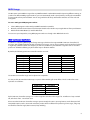
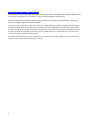
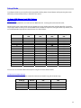
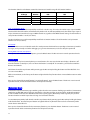
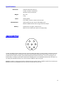
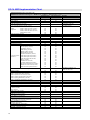
RG-16
User’s Manual
RJM Music Technology, Inc.
RG-16
User’s Manual
Version 1.1
December 15, 2007
RJM Music Technology, Inc.
2525 Pioneer Ave.
Suite 2
Vista, CA 92081
+1-760-597-9450
email: [email protected]
web: www.rjmmusic.com
Copyright © 2007 RJM Music Technology, Inc. All Rights Reserved
RG-16, Amp Gizmo, Loop Gizmo and the RJM logo are trademarks of RJM Music Technology, Inc.
Table of Contents
Table of Contents.................................................................................................................................................... v
Introduction ............................................................................................................................................................1
RG-16 Features ........................................................................................................................................................................................ 1
Controls and Connectors........................................................................................................................................4
Front Panel................................................................................................................................................................................................ 4
Rear Panel.................................................................................................................................................................................................. 4
Setup Examples.......................................................................................................................................................6
MIDI Usage...............................................................................................................................................................8
MIDI Continuous Controllers .............................................................................................................................................................. 8
Backing Up Your Settings: Sysex Dump.......................................................................................................................................... 9
Setup Mode ...........................................................................................................................................................10
To Select MIDI Channel and MIDI Options...................................................................................................................................10
MIDI Channels...................................................................................................................................................................................10
Continuous Controller Ranges ....................................................................................................................................................10
GCX Compatibility Mode...............................................................................................................................................................11
CC Disable ..........................................................................................................................................................................................11
Saving MIDI Channel and Options.............................................................................................................................................11
Invert Mode ............................................................................................................................................................................................11
Momentary Mode.................................................................................................................................................................................11
Group Mode ...........................................................................................................................................................................................12
Quick Setup Buttons............................................................................................................................................................................12
Troubleshooting ...................................................................................................................................................13
Specifications ........................................................................................................................................................14
Amp Connector Pinout.......................................................................................................................................................................14
RG-16 MIDI Implementation Chart......................................................................................................................15
Warranty ................................................................................................................................................................18
v
Introduction
Congratulations on purchasing the RG-16 audio loop and function switcher. The RG-16 has been designed to give you
total control of your amplifier, effects devices, effects pedals or other electronic equipment from a single MIDI
footswitch.
The RG-16 provides eight audio loops, eight function switches and a professional quality audio buffer, all in a compact,
single rack space design. Using the RG-16, you can control virtually any amplifier or effects unit – more than with any
other MIDI-based switching controller. A wide range of custom cables are available to connect the RG-16 to the vast
majority of the amplifiers on the market, and we are continually developing new cables to support additional amplifiers
and equipment.
RG-16 Features
•
•
•
•
•
•
•
•
•
•
•
•
1
Eight audio loops for effect switching (four grouped in series, four independent)
Eight function switches for amplifier control (channels, reverb, effects loops, etc.)
A high-quality audio buffer that can be placed anywhere in the audio path
Two 8-pin DIN jacks allow you to control up to two amps simultaneously
Works with all MIDI footswitches
Responds to Program Change and Continuous Controller messages
Easy programmability via front panel buttons and LEDs
Up to 256 programs can be saved in memory
High-quality relays for optimal sonic performance, compatibility and reliability
Supports both latching and momentary switching modes
Electrically isolated jacks prevent ground loops and allow safe control of multiple amplifiers
Provides phantom power to compatible MIDI devices when used with 7-pin MIDI cable
2
Front Panel
1
2
3
4
5
3
Send 1
Return 1
Input
9
Buffer Out
7
8
Buffer In From Front
6
Rear Panel
Return 2
Send 2
Send 3
11
Return 3
10
Return 4
Send 4
13
Output
Tuner Out
12
15
Send 5/NC
In 5
14
17
Return 5
Out 5/NO
16
15
Send 6/NC
In 6
14
17
Return 6
Out 6/NO
16
15
Send 7/NC
In 7
14
17
Return 7
Out 7/NO
16
15
Send 8/NC
In 8
14
17
Return 8
Out 8/NO
16
Amp 1
18
Amp 2
19
MIDI Thru
21
RJM Music Technology, Inc.
MIDI Out
20
www.rjmmusic.com
MIDI In
22
Power
9VAC only!
23
Controls and Connectors
Front Panel
1. Write Button – Hold this button for three seconds to save the current settings to memory. The LEDs will flash to
confirm.
2. Function Switch Buttons – These buttons turn function switches 1 through 8 on and off. The LED above each
button is lit when the corresponding function switch is on.
The Function Switches are used to control channel switching and other features of an amplifier connected to the RG-16
via the Amp 1 and/or Amp 2 jacks.
3. Power LED – Lights when the RG-16 is powered on.
4. Audio Loop Buttons - These buttons turn audio loops 1 through 8 on and off. The LED above each button is lit
when the corresponding audio loop is on.
5. Input Jack – This jack is connected to the rear panel From Front jack (8), and will pass a mono or stereo signal
through to that connector.
Rear Panel
6. Buffer In – Input to the audio buffer circuit. Using long cables or many effects may degrade the guitar signal, causing
it to lose clarity and definition. The audio buffer is used to “strengthen” the guitar signal and preserve sound quality.
The effect may vary from subtle to significant, depending on the length and quality of cables and type of effects used in
your rig.
7. Buffer Out – Output from the audio buffer circuit.
8. From Front – Signal from the front panel Input Jack (5) appears at this jack.
9. Input – Input to audio loops 1 through 4.
About Audio Loops 1 through 4
Audio Loops 1 through 4 are connected in series. Each loop is connected internally to the next. When a loop is off, the
Send and Receive jacks for that loop are bypassed. The audio signal passes through unchanged. Turning the loop on
routes the guitar signal through the send jack and connects the return jack to the next loop.
10. Send 1 through 4 – Connect your effects inputs here. When the loop is on, the audio signal will be output at the
send jack. When the loop is off, the send jack is grounded and no signal is output.
11. Return 1 through 4 – Connect your effects outputs here. When the loop is on, signal sent to these jacks will be
passed through to the next loop. If nothing is plugged in to the Return jack, the loop is bypassed and activating the
loop will have no effect.
12. Tuner Out – This is an additional output that can be used to connect a tuner. It is connected to the buffer output,
so there is only signal present here if the buffer is in use.
13. Output – Output from loops 1 through 4.
4
About Audio Loops 5 through 8
Audio loops 5 through 8 are fully independent and not connected to each other in any way. Each loop has its own
discrete input and output. When a loop is off, the Send and Receive jacks for that loop are bypassed, and audio signal
passes unchanged from loop input to loop output. When a loop is on, the loop input is connected to the Send jack, and
the loop output is connected to the Return jack.
14. Input (5 through 8) – Signal input to the corresponding audio loop.
15. Send/NC (5 through 8) – Connect your effects inputs here. When the corresponding loop is on, audio signal will
be output at this jack. When the corresponding loop is off, this jack is grounded and no signal is output. (NOTE: This jack
can also be used as a Normally Closed function switch.)
16. Output/NO (5 through 8) – Signal output from the corresponding audio loop. (NOTE: this jack can also be used
as a Normally Open function switch.)
17. Return (5 through 8) – Connect your effects outputs here. When the corresponding loop is on, audio signal
feeding this output will be passed through to the loop output. If nothing is plugged into the Return jack, the loop is
bypassed and activating the loop will have no effect.
18. Amp 1 – Connect an amplifier interface cable from this jack to the footswitch jack of your amplifier. This
connection enables the RG-16 to control all the footswitch-accessible functions of your amplifier.
19. Amp 2 – Connect a second amplifier interface cable from this jack to the footswitch jack of a second amplifier. This
is particularly useful for a stereo rig, where you are using two identical amplifiers, or in an A/B rig, where you have two
amps, but are using only one at a time.
Important: Note that Amp 1 and Amp 2 jacks are switched in unison. Any function switching affects both Amp jacks
simultaneously. For example, turning Function Switch 1 on will turn that designated function on for both Amp 1 and
Amp 2.
20. MIDI Out – MIDI commands and data dumps are sent from this output.
21. MIDI Thru – Any MIDI commands sent to the MIDI In port (22) are output unchanged through this output.
22. MIDI In – Connect your MIDI footswitch (or controller) here to send incoming MIDI commands to the RG-16.
NOTE: If your MIDI footswitch supports phantom power, you can connect a 7-pin MIDI cable here and the RG-16 will
provide phantom power to the footswitch.
23. Power – Connect a 9VAC, 1 Amp power supply here.
Important: Note that the RG-16 uses a 9 Volt AC power supply. Do NOT connect any other power supply to the unit.
Many power supplies are very similar in appearance. Connecting the wrong power supply to the RG-16 can damage the
unit and void your warranty.
5
Setup Examples
Buffer In From Front
Send 1
Send 2
Send 3
Send 4
In 5
Tuner Out
Out 5/NO
In 6
Out 6/NO
In 7
Out 7/NO
In 8
Out 8/NO
Amp 1
Amp 2
MIDI Out
MIDI In
MIDI Thru
Power
9VAC only!
Buffer Out
Input
Return 1
Return 2
Return 3
Return 4
Output
Send 5/NC
Return 5
Send 6/NC
Return 6
Send 7/NC
Return 7
Send 8/NC
Return 8
RJM Music Technology, Inc.
www.rjmmusic.com
From Guitar
To Footswitch Jack
Amp Input
IN
OUT
IN
OUT
From MIDI Controller Out
IN
OUT
IN
OUT
Setup 1 – Four FX Pedals, One Amplifier
This example illustrates a simple configuration for controlling your amp and pedals. Four pedals are connected to
Audio Loops 1 through 4, and can be switched on and off using the Audio Loop buttons 1 through 4. The Amp 1 jack is
connected to the amplifier’s footswitch jack. The Function Switch buttons will control the amp’s channel and other
features (reverb, solo boost, etc.)
Guitar connects to input on front panel
Buffer In
From Front
Send 1
Send 2
Send 3
Send 4
In 5
Tuner Out
Out 5/NO
In 6
Out 6/NO
In 7
Out 7/NO
In 8
Out 8/NO
Amp 1
Amp 2
MIDI Out
MIDI Thru
MIDI In
Power
9VAC only!
Buffer Out
Input
Return 1
Return 2
Return 3
Return 4
Output
Send 5/NC
Return 5
Send 6/NC
Return 6
Send 7/NC
Return 7
Send 8/NC
Amp Input
IN
OUT
IN
Return 8
RJM Music Technology, Inc.
www.rjmmusic.com
To Footswitch Jack
OUT
From MIDI Controller Out
Amp Input
IN
OUT
IN
OUT
To Footswitch Jack
Setup 2 – Four FX Pedals, Two Amps
This is a two amp configuration – you can have either amp on, both amps on, or both amps off. When Audio Loop 5 is
on, Amp 1 is active, and when Audio Loop 6 is on, Amp 2 is active. An amp that is not active will have its input muted.
Both amplifier switching jacks are used. The amps can be switched simultaneously or independently, depending on
the amplifiers and amplifier interface cables being used. In a configuration like this, an isolation transformer may be
needed to eliminate noise caused by ground loops.
6
Guitar connects to input on front panel
Buffer In
From Front
Send 1
Send 2
Send 3
Send 4
To Tuner
To Amplifier Input
In 5
Tuner Out
Out 5/NO
In 6
Out 6/NO
In 7
Out 7/NO
In 8
Out 8/NO
Amp 1
Amp 2
MIDI Out
MIDI Thru
MIDI In
Power
9VAC only!
Buffer Out
Input
Return 1
Return 2
Return 3
Return 4
Output
Send 5/NC
Return 5
Send 6/NC
Return 6
Send 7/NC
Return 7
Send 8/NC
Return 8
RJM Music Technology, Inc.
www.rjmmusic.com
To Footswitch Jack
IN
OUT
IN
IN
OUT
OUT
IN
OUT
From MIDI Controller Out
IN
OUT
IN
OUT
IN
OUT
IN
OUT
Setup 3 – Eight FX Pedals, Tuner, One Amplifier
In this configuration, all of the audio loops are connected in series to switch 8 different pedals. The audio buffer is connected
before the pedals, and the “From Front” jack is used, with the guitar plugged into the RG-16’s front panel input.
Amp Input
To Footswitch Jack
Send
Receive
Buffer In From Front
Send 1
Send 2
Send 3
Send 4
In 5
Tuner Out
Out 5/NO
In 6
Out 6/NO
In 7
Out 7/NO
In 8
Out 8/NO
Amp 1
Amp 2
MIDI Out
MIDI Thru
MIDI In
Power
9VAC only!
Buffer Out
Input
Return 1
Return 2
Return 3
Return 4
Output
Send 5/NC
Return 5
Send 6/NC
Return 6
Send 7/NC
Return 7
Send 8/NC
Return 8
RJM Music Technology, Inc.
www.rjmmusic.com
From Guitar
IN
OUT
IN
Input
OUT
Output
Rack FX 1
Input
Output
Rack FX 2
From MIDI Controller Out
MIDI Input
IN
OUT
IN
MIDI
Thru
MIDI Input
OUT
Setup 4 – Four FX Pedals, 2 FX Units in Amp’s Loop
This example shows how you can use the RG-16 in a system where there are effects connected to the amp’s input and effects in
the amp’s effects loop. The output of the first four loops is connected to the amp’s input, and loops 5 and 6 are connected to the
amp’s effects loop. The RG-16’s MIDI Thru is used to pass MIDI commands to the rack effect units, allowing one MIDI controller to
control the entire rig.
7
MIDI Usage
The RG-16 can receive MIDI messages from any MIDI footswitch or other MIDI controller. By storing different settings, or
“patches” for different MIDI program numbers, you can automatically recall a stored patch by sending the correct MIDI
program number from your footswitch. You can assign which audio loops and function switches are on for each and
every patch.
To save a setting to a MIDI program number:
•
•
•
Select a MIDI program number with your MIDI footswitch or controller.
Manually select the desired state of each Function Switch and/or Audio Loop using the RG-16’s front panel buttons.
Hold down the Write Button (1) until the LEDs flash.
You can save up to 256 patches, using MIDI program numbers 1 through 128 in MIDI banks 0 and 1.
MIDI Continuous Controllers
In addition to supporting MIDI Program Change messages, the RG-16 also supports MIDI Continuous Controller (CC)
messages. Using a MIDI controller capable of sending CC messages, you can assign a button on the controller to control
a single loop or function switch. For example, you can have a button on your controller assigned to turn an overdrive
pedal on or off without affecting any of the other loops or function switches.
By default, the following continuous controller numbers are used:
Audio Loop
Loop 1
Loop 2
Loop 3
Loop 4
Loop 5
Loop 6
Loop 7
Loop 8
CC number
80
81
82
83
84
85
86
87
Function Switch
Function 1
Function 2
Function 3
Function 4
Function 5
Function 6
Function 7
Function 8
CC number
88
89
90
91
92
93
94
95
The continuous controller ranges can be adjusted in Setup Mode.
It is also possible to control the Audio Loops in pairs to allow switching of stereo effects. The CC numbers for stereo
operation are as follows:
Audio Loops
Loops 1 and 2
Loops 3 and 4
Loops 5 and 6
Loops 7 and 8
CC number
52
53
54
55
Each Continuous Controller message has a value assigned to it. Values in the range of 0…63 will turn a loop or switch
off, and values of 64…127 will turn it on.
Please note that Continuous Controller messages operate exactly the same as pressing buttons on the front panel. All
Setup Mode options such as invert and momentary modes will be in effect when processing CC messages, and group
mode will be active for single (but not stereo) loop switching.
8
Backing Up Your Settings: Sysex Dump
A Sysex (System Exclusive) data dump will send the current RG-16 system configuration out through the MIDI Out port.
You can then save this data to your computer, or copy the settings directly to another RG-16.
Hold down the Audio Loop 5 button while powering up the RG-16, and the RG-16 will immediately send the Sysex
Dump. It only takes a couple of seconds to complete.
If you wish to copy settings from on RG-16 to another, connect the MIDI Output of the transmitting unit to the MIDI
Input of the receiving unit, then power up the transmitting unit while holding down the Audio Loop 5 button. (Note
that the receiving RG-16 must be in normal operating mode to receive data.) The receiving unit will display a progress
bar graph on the Audio Loop LEDs. The transfer goes very quickly, taking only a couple of seconds. In the case of an
error, the receiving unit will flash all LEDs 5 times.
Once the transfer completes, the receiving unit will reset, then return to normal operating mode. The receiving unit
now has an exact copy of the transmitting unit’s settings.
9
Setup Mode
To configure the RG-16, you must first enter Setup Mode. Holding down selected buttons while powering the unit on
will bring up selected setup modes, as detailed in this section.
To Select MIDI Channel and MIDI Options
MIDI Channels
The RG-16 is set by default to send and receive on MIDI Channel 1. To change the send/receive channel:
Hold the Audio Loop 1 button while powering the RG-16 on. Keep holding the button until the LEDs flash. The Audio
Loop buttons will then allow you to select the MIDI channel the RG-16 responds to. Using the Audio Loop buttons, turn
on and off the Audio Loop LEDs to select the channel as shown below:
MIDI Channel
1
2
3
4
5
6
7
8
9
10
11
12
13
14
15
16
Audio Loop 1
LED
OFF
ON
OFF
ON
OFF
ON
OFF
ON
OFF
ON
OFF
ON
OFF
ON
OFF
ON
Audio Loop 2
LED
OFF
OFF
ON
ON
OFF
OFF
ON
ON
OFF
OFF
ON
ON
OFF
OFF
ON
ON
Audio Loop 3
LED
OFF
OFF
OFF
OFF
ON
ON
ON
ON
OFF
OFF
OFF
OFF
ON
ON
ON
ON
Audio Loop 4
LED
OFF
OFF
OFF
OFF
OFF
OFF
OFF
OFF
ON
ON
ON
ON
ON
ON
ON
ON
You can also set a few other MIDI-related options using the Function Switch buttons:
Continuous Controller Ranges
The Function Switch 1 and 2 buttons control the Continuous Controller range for all Audio Loops:
Audio Loop
CC Range
80…87 (default)
88…95
64…71
56…63
GCX
Number
1
2
3
4
Function Switch 1
LED
OFF
ON
OFF
ON
Function Switch 2
LED
OFF
OFF
ON
ON
10
The Function Switch 3 and 4 buttons control the Continuous Controller range for all Function Switches:
Function Switch
CC Range
80…87
88…95 (default)
64…71
56…63
GCX
Number
1
2
3
4
Function Switch 3
LED
OFF
ON
OFF
ON
Function Switch 4
LED
OFF
OFF
ON
ON
GCX Compatibility Mode
Function Switch 5 turns on GCX compatibility mode for the Audio Loops. This makes the Audio Loops respond to MIDI
commands like the GCX switcher, manufactured by Voodoo Lab. In GCX compatibility mode, the Audio Loops respond
only to Continuous Controller messages on MIDI channel 16, regardless of the MIDI channel setting. The GCX number is
set by Function Switches 1 and 2 (see above).
Function Switch 6 turns on GCX compatibility mode for the Function Switches. The GCX number is set by Function
Switches 3 and 4 (see above).
CC Disable
Function Switch 7 turns on CC Disable mode. This mode prevents the RG-16 from responding to Continuous Controller
messages, and is primarily used when debugging a rig. In most circumstances, it’s best to keep this option off.
Saving MIDI Channel and Options
Once you’ve set the MIDI channel and options, press the Write button. The RG-16 is now in normal operational mode.
Invert Mode
Some amplifiers may have inverted polarity on some functions. This can cause the RG-16 to display a function as off
when the function is actually on, and as on when the function is actually off. To correct this, you must first switch the
RG-16 to Invert Mode.
Hold down the Audio Loop 2 button while powering up the RG-16. Keep holding the button until the LEDs flash. You
are now in Invert Mode.
While in Invert Mode, use the front panel buttons to light the LED of any function that is inverted. Make certain no other
LED is lit.
Once you’ve selected the inverted function’s associated button(s), press the Write button. The RG-16 is now in normal
operational mode, and the inverted functions should operate correctly.
Momentary Mode
Some devices require momentary-type switching, rather than the more common latching-type switches. (A momentary
switch changes OFF/ON state by closing its contacts for a short time and then re-opening them. In Momentary Mode,
the RG-16 switches will close for 100 milliseconds before opening again.) Momentary mode is typically only used for
Function Switches or Audio Loops that are being used as function switches.
To enter Momentary Mode, hold down the Audio Loop 3 button while powering up the RG-16. Keep holding the button
until the LEDs flash. Use the front panel buttons to light the LED of any function that needs to be momentary. Make
certain that no other LED is lit.
Once you’ve selected the buttons for the momentary functions, press the Write button. The RG-16 is now in normal
operational mode and the momentary functions should operate correctly.
11
Group Mode
The Group feature allows you define a group of buttons where pressing one button of the group turns that button on
and turns all other buttons in the group off. This is typically used for function switches that control which channel is
selected on an amplifier. This prevents the RG-16 from trying to activate more than one amp channel at a time.
To enter Group mode, hold down the Audio Loop 4 button while powering up the RG-16. Keep holding the button until
the LEDs flash.
Use the front panel buttons to light the LED of any function that should be in the group. Make sure that no other LEDs
are lit.
Note: The groups for Audio Loops and Function Switches are separate. If you set both Audio Loops and Function
Switches to be part of a group, pressing an Audio Loop button will only affect other Audio Loops, and pressing a
Function Switch button will only affect other Function Switches.
Once you’ve selected the functions that need to be grouped, press the Write button. The RG-16 is now in normal
operational mode and the grouped buttons will now only allow one button to be selected at a time.
Quick Setup Buttons
Quick Setup buttons are provided to quickly set up the Function Switches for common configurations. Which
configuration you use depends on the number of channels your amplifier has, and whether the amplifier uses
momentary switching or not.
To use this feature, hold one of the following buttons while powering up the RG-16. Hold the button until the LEDs
flash. The RG-16 will configure the Function Switch buttons as follows:
Hold Function Switch 1: No switches momentary or grouped. (Default setting)
Hold Function Switch 2: First two switches grouped, no switches momentary. (Most 2 channel amps)
Hold Function Switch 3: First three switches grouped, no switches momentary. (Most 3 channel amps)
Hold Function Switch 4: First four switches groups, no switches momentary. (Most 4 channel amps)
Hold Function Switch 5: All switches momentary, none grouped. (Rivera M and S amps)
Hold Function Switch 6: First two switches grouped and momentary.
Hold Function Switch 7: First three switches grouped and momentary. (Bogner Ecstasy, Traynor YCS100)
Hold Function Switch 8: First four switches grouped and momentary. (Marshall Mode 4)
Once the button has been held and the LEDs have flashed, release the button and the RG-16 will go directly to normal
operating mode.
12
Troubleshooting
Problem: The LEDs don’t flash when you hold down the Write Button.
Solution: The RG-16 did not receive a MIDI Program Change message. First, verify that you have a valid MIDI
connection. The MIDI output of your MIDI controller should be connected to the MIDI input of the RG-16 by a MIDI
cable that’s known to be working correctly. The next most likely cause is that the RG-16 is set to a different MIDI channel
than your MIDI controller. Check both devices to insure that they’re set to the same channel. On the RG-16, the MIDI
channel is set to 1 by default and can be changed in Setup Mode.
Problem: There is excessive hum in the audio signal.
Solution: There are a number of reasons that this might happen, but it’s often a grounding issue. The grounds are left
floating on the RG-16 where possible, so you may need to tie the RG-16 ground to the audio ground in order to
eliminate hum. This can be done by either grounding the RG-16 chassis, or by using the RG-16’s buffer. If using the RG16 in a multiple amplifier setup, you may need to use an isolation transformer on one or more amps to eliminate hum
caused by ground loops.
Problem: I’m trying to control my amplifier with the RG-16’s function switches, and it’s not working or behaving
erratically.
Solution: This can happen when using the wrong amplifier interface cable, or if the RG-16 is not configured correctly
for your amp. Check the instruction sheet that came with your amplifier interface cable, or check the Setup Mode
section for more information on how to configure. You can also check contact us at RJM Music for assistance. We’d be
happy to help you out.
More troubleshooting tips can be found in the FAQ section of www.rjmmusic.com.
13
Specifications
Dimensions
Weight
Power
Phantom Power
Memory
Standard 1U EIA rack enclosure
19 (W) x 1.75 (H) x 7.25 (D) inches
48.3 (W) x 4.5 (H) x 18.5 (D) cm
4 lbs, 4 oz
1.8 kg
9VAC @ 450mA
5.5mm OD, 2.5mm ID x 9.5mm barrel connector
9VAC provided over pins 6 and 7 of the MIDI In jack
Maximum 500mA current when using provided AC adaptor
256 programs, arranged in 2 banks of 128
Memory is non-volatile and requires no backup battery
Amp Connector Pinout
7
3
6
1
8
4
5
2
The RG-16 amplifier function switch connectors are female DIN-8 jacks. When a Function Switch is activated on the RG16, the corresponding pin is shorted to the connector’s ground (shield). Activating Function Switch 1 shorts pin 1 (as
numbered above) to the connector’s ground. Activating Function Switch 2 shorts pin 2, and so on. This happens on
both the Amp 1 and Amp 2 jacks. Please note that the amplifier jacks are not electrically connected to each other or to
any other part of the RG-16 circuit, so it’s safe to connect a different amp to each jack.
RJM Music produces a wide range of cables to allow the RG-16 to control various amplifier models. Please contact your
RJM Music dealer or the RJM Music web site to find the correct cable for your amp.
14
RG-16 MIDI Implementation Chart
MIDI Implementation Chart v 2.0 (Page 1 of 3)
Manufacturer: RJM Music Technology, Inc. Model: RG-16 Version: 1 Date: December 15, 2007
Transmit/Export
Recognize/Import
1. Basic Information
MIDI Channels
1-16
1-16
Note Numbers
No
No
Program change
1-128
1-128
Bank Select Response? (Yes/No)
No
No
If yes, list banks utilized in remarks column
No
No
Mode 1: Omni-On, Poly (Yes/No)
No
No
Mode 2: Omni-On, Mono (Yes/No)
Modes
supported :
Yes
Yes
Mode 3: Omni-Off, Poly (Yes/No)
Yes
Yes
Mode 4: Omni-Off, Mono (Yes/No)
No
No
Multi Mode (Yes/No)
Note-On Velocity (Yes/No)
No
No
Note-Off Velocity (Yes/No)
No
No
Channel Aftertouch (Yes/No)
No
No
Poly (Key) Aftertouch (Yes/No)
No
No
Pitch Bend (Yes/No)
No
No
Active Sensing (Yes/No)
No
No
System Reset (Yes/No)
No
No
Tune Request (Yes/No)
No
No
No
No
Sample Dump Standard (Yes/No)
No
No
Device Inquiry (Yes/No)
No
No
File Dump (Yes/No)
No
No
MIDI Tuning (Yes/No)
No
No
Master Volume (Yes/No)
No
No
Master Balance (Yes/No)
No
No
Notation Information (Yes/No)
No
No
Universal System Turn GM1 System On (Yes/No)
Exclusive:
No
No
Turn GM2 System On (Yes/No)
No
No
Turn GM System Off (Yes/No)
No
No
DLS-1 (Yes/No)
No
No
File Reference (Yes/No)
No
No
Controller Destination (Yes/No)
No
No
Key-based Instrument Ctrl (Yes/No)
No
No
Master Fine/Coarse Tune (Yes/No)
No
No
Other Universal System Exclusive
15
Manufacturer or Non-Commercial System Exclusive
Yes
Yes
NRPNs (Yes/No)
RPN 00 (Pitch Bend Sensitivity) (Yes/No)
RPN 01 (Channel Fine Tune) (Yes/No)
RPN 02 (Channel Coarse Tune) (Yes/No)
RPN 03 (Tuning Program Select) (Yes/No)
RPN 04 (Tuning Bank Select) (Yes/No)
RPN 05 (Modulation Depth Range) (Yes/No)
2. MIDI Timing and Synchronization
MIDI Clock (Yes/No)
Song Position Pointer (Yes/No)
Song Select (Yes/No)
Start (Yes/No)
Continue (Yes/No)
Stop (Yes/No)
MIDI Time Code (Yes/No)
MIDI Machine Control (Yes/No)
MIDI Show Control (Yes/No)
If yes, MSC Level supported
3. Extensions Compatibility
General MIDI compatible? (Level(s)/No)
Is GM default power-up mode? (Level/No)
DLS compatible? (Levels(s)/No)
(DLS File Type(s)/No)
Standard MIDI Files (Type(s)/No)
XMF Files (Type(s)/No)
SP-MIDI compatible? (Yes/No)
No
No
No
No
No
No
No
No
No
No
No
No
No
No
No
No
No
No
No
No
No
No
No
No
No
No
No
No
No
No
No
No
No
No
No
No
No
No
No
No
No
No
No
No
No
Remarks
Channel 1 is set by default
Responds to CC#0 only,
Uses banks 0 and 1
RJM Music Technology, Inc
Manuf. ID: 00 01 5B
MIDI Implementation Chart v 2.0 (Page 2 of 3)
Manufacturer: RJM Music Technology, Inc. Model: RG-16 Version: 1 Date: December 15, 2007
Control #
Function
Transmitted (Y/N)
Recognized (Y/N)
0
Bank Select (MSB)
N
Y
1
Modulation Wheel (MSB)
N
N
2
Breath Controller (MSB)
N
N
3
N
N
4
Foot Controller (MSB)
N
N
5
Portamento Time (MSB)
N
N
6
Data Entry (MSB)
N
N
7
Channel Volume (MSB)
N
N
8
Balance (MSB)
N
N
9
N
N
10
Pan (MSB)
N
N
11
Expression (MSB)
N
N
12
Effect Control 1 (MSB)
N
N
13
Effect Control 2 (MSB)
N
N
14
N
N
15
N
N
16
General Purpose Controller 1 (MSB)
N
N
17
General Purpose Controller 2 (MSB)
N
N
18
General Purpose Controller 3 (MSB)
N
N
19
General Purpose Controller 4 (MSB)
N
N
20
N
N
21
N
N
22
N
N
23
N
N
24
N
N
25
N
N
26
N
N
27
N
N
28
N
N
29
N
N
30
N
N
31
N
N
32
Bank Select (LSB)
N
N
33
Modulation Wheel (LSB)
N
N
34
Breath Controller (LSB)
N
N
35
N
N
36
Foot Controller (LSB)
N
N
37
Portamento Time (LSB)
N
N
38
Data Entry (LSB)
N
N
39
Channel Volume (LSB)
N
N
40
Balance (LSB)
N
N
41
N
N
42
Pan (LSB)
N
N
43
Expression (LSB)
N
N
44
Effect Control 1 (LSB)
N
N
45
Effect Control 2 (LSB)
N
N
46
N
N
47
N
N
48
General Purpose Controller 1 (LSB)
N
N
49
General Purpose Controller 2 (LSB)
N
N
50
General Purpose Controller 3 (LSB)
N
N
51
General Purpose Controller 4 (LSB)
N
N
52
N
Y
53
N
Y
54
N
Y
55
N
Y
56
N
Y
57
N
Y
58
N
Y
59
N
Y
60
N
Y
61
N
Y
62
N
Y
63
N
Y
Remarks
Banks 0 and 1 only
Use CC#0 instead
Audio Loops 1 and 2
Audio Loops 3 and 4
Audio Loops 5 and 6
Audio Loops 7 and 8
Alt. CC Range 2
Alt. CC Range 2
Alt. CC Range 2
Alt. CC Range 2
Alt. CC Range 2
Alt. CC Range 2
Alt. CC Range 2
Alt. CC Range 2
16
MIDI Implementation Chart v 2.0 (Page 3 of 3)
Manufacturer: RJM Music Technology, Inc. Model: RG-16 Version: 1 Date: December 15, 2007
Control #
Function
Transmitted (Y/N)
Recognized (Y/N)
64
Sustain Pedal
N
Y
65
Portamento On/Off
N
Y
66
Sostenuto
N
Y
67
Soft Pedal
N
Y
68
Legato Footswitch
N
Y
69
Hold 2
N
Y
70
Sound Controller 1 (default: Sound Variation)
N
Y
71
Sound Controller 2 (default: Timbre / Harmonic Quality)
N
Y
72
Sound Controller 3 (default: Release Time)
N
N
73
Sound Controller 4 (default: Attack Time)
N
N
74
Sound Controller 5 (default: Brightness)
N
N
75
Sound Controller 6 (GM2 default: Decay Time)
N
N
76
Sound Controller 7 (GM2 default: Vibrato Rate)
N
N
77
Sound Controller 8 (GM2 default: Vibrato Depth)
N
N
78
Sound Controller 9 (GM2 default: Vibrato Delay)
N
N
79
Sound Controller 10 (GM2 default: Undefined)
N
N
80
General Purpose Controller 5
N
Y
81
General Purpose Controller 6
N
Y
82
General Purpose Controller 7
N
Y
83
General Purpose Controller 8
N
Y
84
Portamento Control
N
Y
85
N
Y
86
N
Y
87
N
Y
88
N
Y
89
N
Y
90
N
Y
91
Effects 1 Depth (default: Reverb Send)
N
Y
92
Effects 2 Depth (default: Tremolo Depth)
N
Y
93
Effects 3 Depth (default: Chorus Send)
N
Y
94
Effects 4 Depth (default: Celeste [Detune] Depth)
N
Y
95
Effects 5 Depth (default: Phaser Depth)
N
Y
96
Data Increment
N
N
97
Data Decrement
N
N
98
Non-Registered Parameter Number (LSB)
N
N
99
Non-Registered Parameter Number(MSB)
N
N
100
Registered Parameter Number (LSB)
N
N
101
Registered Parameter Number(MSB)
N
N
102
N
N
103
N
N
104
N
N
105
N
N
106
N
N
107
N
N
108
N
N
109
N
N
110
N
N
111
N
N
112
N
N
113
N
N
114
N
N
115
N
N
116
N
N
117
N
N
118
N
N
119
N
N
120
All Sound Off
N
N
121
Reset All Controllers
N
N
122
Local Control On/Off
N
N
123
All Notes Off
N
N
124
Omni Mode Off
N
N
125
Omni Mode On
N
N
126
Poly Mode Off
N
N
127
Poly Mode On
N
N
17
Remarks
Alt. CC Range 1
Alt. CC Range 1
Alt. CC Range 1
Alt. CC Range 1
Alt. CC Range 1
Alt. CC Range 1
Alt. CC Range 1
Alt. CC Range 1
Audio Loop 1
Audio Loop 2
Audio Loop 3
Audio Loop 4
Audio Loop 5
Audio Loop 6
Audio Loop 7
Audio Loop 8
Function Switch 1
Function Switch 2
Function Switch 3
Function Switch 4
Function Switch 5
Function Switch 6
Function Switch 7
Function Switch 8
Warranty
RJM Music Technology, Inc. warrants this product against any defects in material or workmanship for a period of one
year from the original date of purchase.
Should you experience any difficulty with this RJM Music product, please contact us as described below. If it is
determined that the product has become defective within the warranty period and must be returned to the factory,
RJM Music Technology will issue a Returned Merchandise Authorization (RMA) number and shipping and packaging
instructions.
RJM Music Technology will repair or replace the product free of charge, provided it is returned freight prepaid to RJM
Music Technology with a copy of a valid receipt and RMA number. Return shipping will be paid by RJM Music
Technology within the U.S. only.
This warranty is transferable provided the current owner has the original dated purchase receipt and can provide a
copy of it when submitting the warranty claim.
This warranty shall not apply to any goods that have been repaired or altered by anyone other than RJM Music
Technology, Inc. or an RJM Music Technology authorized service center. This warranty does not cover damage to the
product resulting from accidents or misuse. This is your sole warranty. There are no warranties which extend beyond
the terms described herein.
RJM Music Technology, Inc.
2525 Pioneer Ave.
Suite 2
Vista, CA 92081
+1-760-597-9450
E-Mail: [email protected]
18