1
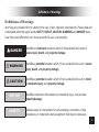
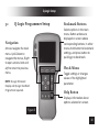
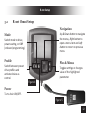
User Manual i-Drive Precision Mini Proportional Joystick Copyright ©2014 Stealth Products, Inc. Copyright © 2014 Stealth Products, LLC. All rights reserved. Published by Stealth Products, Inc. August 21, 2015 P44D01R1 Customer Satisfaction Stealth Products strives for 100% customer satisfaction. Your complete satisfaction is important. Please contact us with feedback or suggested changes that will help improve the quality and usability of our proportional drive products. You may reach us at: 104 John Kelly Drive, Burnet Texas 78611 Phone: (512) 715-9995 Toll-Free: 1(800) 965-9229 Fax: (512) 715-9954 Toll-Free: 1(800) 806-1225 [email protected] www.stealthproducts.com ii Definitions of Warnings Definitions of Warnings Warnings are included for the safety of the user, client, operator and property. Please read and understand what the signal words SAFETY, NOTICE, CAUTION, WARNING and DANGER mean, how they could affect the user, those around the user, and property. DANGER Identifies an imminent situation which (if not avoided) will result in severe injury, death, and property damage. WARNING Identifies a potential situation which (if not avoided) will result in severe injury, death, and property damage. CAUTION Identifies a potential situation which (if not avoided) will result in minor to moderate injury, and property damage. NOTICE Identifies important information not related to injury, but possible property damage. SAFETY Indicates steps or instructions for safe practices, reminders of safe procedures, or important safety equipment that may be necessary. iii Important Information IMPORTANT INFORMATION! All persons responsible for fitting, adjustment, and daily use of the devices discussed in these instructions must be familiar with and understand all safety aspects of the devices mentioned. In order for our products to be used successfully you must: Read and understand all instructions and warnings Maintain our products according to our instructions on care and maintenance Devices should be installed and adjusted by a trained technician Supplier Reference Supplier: Telephone: Address: Purchase Date: Model: iv Important Information NOTICE Store these instructions in a safe place so they may be referenced as necessary. Read and understand all instructions prior to the use of the product If this document contains information you do not understand, or there are concerns about safety or operation, contact your supplier WARNING ALWAYS have these products fitted, applied, and installed exclusively by a trained technician with a full understanding of wheelchair drive controls. Failure to adhere to instructions and warnings in this document may result in property damage, injury or death. Product misuse due to failure of following instructions will void the warranty Immediately discontinue use if any function is compromised, parts are missing, loose, or shows signs of excessive wear. Consult with your supplier for repair, adjustment or replacement v Table of Contents Edition Notice ............................................................................................................................. ii Definition of Warnings ............................................................................................................... iii Important Information .............................................................................................................. iv Table of Contents ...................................................................................................................... vi 1.0 Safety .................................................................................................................................. 1 2.0 I-DRIVE PMPJ (PMPJ for i-Drive) ......................................................................................... 3 2.1 Factory Settings .............................................................................................................. 4 2.2 Joystick Installation ........................................................................................................ 5 2.3 Connecting ...................................................................................................................... 6 2.4 Joystick Operation .......................................................................................................... 7 3.0 System Set Up .................................................................................................................... 9 3.1 Q-Logic Programmer Setup........................................................................................... 10 3.2 R-net Omni Setup ......................................................................................................... 12 3.3 i-Drive Programmer Software (APS).............................................................................. 15 3.3.1 Software Installation ............................................................................................... 16 3.3.2 Getting Started........................................................................................................ 17 3.3.3 Setup Wizard........................................................................................................... 19 3.3.4 Diagnostics .............................................................................................................. 21 vi Table of Contents 3.3.5 Configuration Mode (Config Mode) .......................................................................23 A. Sensor Channel Assignment ......................................................................................25 B. Mechanical Channel Assignment ..............................................................................26 C. Double-Tab Settings ..................................................................................................27 4.0 Care & Maintenance .........................................................................................................29 4.1 Daily Maintenance Check ..............................................................................................30 4.2 Weekly Maintenance Check ..........................................................................................30 4.3 Monthly Maintenance Check ........................................................................................31 4.4 Water Contact ...............................................................................................................31 4.5 In Case of Damage or Malfunction ................................................................................31 4.6 Cleaning ........................................................................................................................32 4.7 Disinfecting ...................................................................................................................32 5.0 Electromagnetic Interference (EMI) ..................................................................................32 6.0 Warranty ...........................................................................................................................33 7.0 Notes ..................................................................................................................................a vii Safety 1.0 Safety WARNING DISCONTINUE USE if any component stops functioning correctly. INTIAL SETUP AND DRIVING should be done in an open area, free of obstacles, until the user is fully capable of driving safely ALWAYS evaluate how factors such as tone, fatigue, position, and physical involvement will impact driving ability ALWAYS have attendant supervision if required TURN OFF the power chair and I-DRIVE PMPJ when cleaning, disinfecting, maintaining, repairing, servicing the I-DRIVE PMPJ, or during user transfers NEVER over tighten clamps or fasteners. Over tightening will damage components and fasteners Environment Safety ALWAYS operate or store the I-DRIVE PMPJ in safe temperature of -40° to +149°F (-40° to +65°C) DO NOT operate or leave the I-DRIVE PMPJ in rain, snow, sleet, hail, or damp environment DO NOT expose the I-DRIVE PMPJ to water, condensation, icing, or dampness 1DO NOT operate in the shower DO NOT operate or store near open flame, flammable, or combustible products WARNING User Transfer TURN OFF the power chair and I-DRIVE PMPJ when moving, transferring, or lifting the user Moving the Chair TURN OFF the power chair and I-DRIVE PMPJ when moving or transporting the wheelchair DO NOT lift the wheelchair by any I-DRIVE PMPJ component Terrain Safety DO NOT use on surfaces that you are unsure of DO NOT use on the edge of a stream, lake, or ocean DO NOT use on roads, streets, or high automotive traffic areas ALWAYS follow instructions provided by the wheelchair manufacturer about driving on safe surfaces, angle of ascent, and angle of descent Joystick Safety DO NOT use if joystick handle is damaged, missing, or cracked DO NOT use if joystick boot is torn DO NOT use if joystick does not return to neutral position independently DO NOT use if joystick does not move to and from neutral position smoothly 2 i-Drive PMPJ 2.0 i-Drive PMPJ Precision Mini Proportional Joystick The i-Drive Precision Mini Proportional Joystick (PMPJ) Package includes: PMPJ i-Drive Control Interface Egg Switch 1/8” Mono Dongle ARMS260 Swing-Away Mount i-Drive Control Interface ARMS260 Swing-Away Mount 3 Egg Switch Figure A 1/8” Mono Dongle i-Drive PMPJ Additional Mounting Options GAT486 Figure B GAT497 SM670 SBM851 Gatlin Mount 2.2 Bib Mount Factory Settings 6 5 4 3 2 1 Port 6 Port 5 Port 4a Port 4b Port 3a Port 3b Port 2 Port 1 Swing-Away Arm Unassigned Unassigned Reset/Mode Unassigned Unassigned Unassigned Prop Left/Right Prop Fwd./Rev. (micoUSB) (micoUSB) Egg Switch (1/8” Mono) (1/8” Mono) (1/8” Mono) Joystick Joystick The i-Drive interface contains 6 mini USB input ports. Ports 1, 2, 5, and 6 are for proximity sensors or mini-joystick. Ports 3 and 4 are for mechanical switches. Note: The dongle is required for mechanical input, and provides a double input for “mechanical” ports. One dongle is included, and additional dongle are available for purchase. The associated i-Drive Programmer Software allows for quick port assignability and higher level of sensor adjustability. 4 I-DRIVE PMPJ 2.2 Installation Stealth’s I-DRIVE PMPJ joystick housing comes with two threaded holes for mounting system fastening. Two #10-32 X 3/8" Button Head Screws supplied SM671 ARMS260-PMPJ SM670 5 Swing-Away Arm Mounting SBM851 Bib Mount I-DRIVE PMPJ Installation GAT486 GAT497 Mounting Mounting 2.3 Connecting The i-Drive Control Interface (Figure A) plugs directly into the power chair’s control interface using the supplied DB-9 connector (Figure 1). Depending on the type of interface, the location of the port varies. 9-Pin Connector Figure 1 Q-Logic Drive Control System Q-Logic SCIM R-net Omni Specialty Control Interface Port 2 Port 1 6 I-DRIVE PMPJ Operation 2.3 Joystick Operation The I-DRIVE PMPJ gives the user the ability to operate their wheelchair drive parameters with smooth and precise control in 360 degrees. Before Use Ensure the wheelchair and I-DRIVE PMPJ are correctly setup and adjusted to the user’s needs If the I-DRIVE PMPJ does not perform as specified, turn off the wheelchair and repeat setup or contact your supplier Joystick Setup It is important to properly install the I-DRIVE PMPJ for the user. Take care during the assessment to identify joystick placement allowing maximum user access and control. Do not position the joystick where the hand may be obstructed from moving in any direction. Joystick Directions The front divot (Figure 2) represents the front of the joystick, or Forward, as the factory setting. 7 I-DRIVE PMPJ Operation Backward Left Right Forward Front Divot Figure 2 8 System Set Up 3.0 System Setup WARNING ALL setups should be performed by a trained technician. CAUTION MANUALLY disengage drive motors prior to setting up chair's electronics REFER to power chair’s user manual for important instructions ALWAYS use a slow speed when first operating the I-DRIVE PMPJ 9 Q-Logic Setup 3.1 Q-Logic Programmer Setup Navigation Arrows navigate the main menu. Up & Down to navigate the menus, Right to open a menu item and Left to return to previous menu. NOTE: Q-Logic Enhanced Display and Q-Logic Handheld Programmer required. Bookmark Buttons Selects options in the main menu. Button actions are displayed on screen above corresponding buttons. In other menus hold button to bookmark settings, and press button to quickly go to bookmark. Plus & Minus Toggle settings or changes values of the highlighted parameter. Help Button Displays information about options selected on screen. Figure 3 10 Q-Logic Setup CAUTION Manually disengage drive motors Prior to setting up power chair’s electronics to recognize the i-Drive input, ensure that the chair’s power is off, and the motors are manually disengaged. This will prevent unintentional chair movement. 1. Plug in the Q-Logic Handheld Programmer to the back of the Q-Logic ED (Enhanced Display) or to the standalone Joystick if SCIM (Specialty Control Input Module) is in use, power on the chair 2. On the Q-Logic programmer, navigate to Program Adjustments > Specialty Control > Active Device 3. Toggle Active Device to 5-Switch with the plus & minus buttons. 4. Unplug the Q-Logic Handheld Programmer and turn off the system. The chair should now be programmed to recognize the i-Drive. Be sure to re-engage the motors before operation NOTICE If using Q-Logic Specialty Control Input Module (SCIM), you will need any type of mechanical switch to plug into the power port of the standalone Joystick to power ON/OFF the chair and ensure the SCIM as master 11 control R-net Setup 3.2 R-net Omni Setup Navigation Up & Down button to navigate the menus, Right button to open a menu item and Left button to return to previous menu. Mode Switch mode to drive, power seating, or OBP (onboard programming). Profile Plus & Minus Switch between preset drive profiles and activate device as control. Toggles settings or changes value of the highlighted parameter. Figure 4 Power Turns chair ON/OFF. Figure 5 12 R-net Setup 1. Plug in the R-net Programming Dongle (Figure 5) in line with the Omni display and chair’s electronics, and then power on the chair. 2. Press the mode button till you get to the OBP (On-Board Programming) menu. The OBP menu will appear as an hourglass while loading. 3. With the navigation buttons, navigate to Omni > Global > Sleep 12V, and toggle Sleep 12V to On with the plus & minus buttons. 4. Go back to the Omni menu, and go to Omni > Port 1 (or Port 2 if i-Drive is in Port 2). 5. In the Port menu, toggle SID to Swi with the plus & minus buttons. 6. In the Port menu, go to Switches. 7. In the Switch menu, toggle Switch Detect to Off with the plus & minus buttons. 8. In the Switch menu, toggle 9 Way Detect to Off with the plus & minus buttons. 9. Go back to the Omni menu, and go to Profiled. 10. In the Profiled menu, configure a profile to use the port for the i-Drive. 11. Power off the chair, remove the programming dongle, and reconnect the display. The chair should now be programmed to recognize the i-Drive. Be sure to re-engage the motors before operation. 13 Profile configurator application for i-Drive® Drive Controls 14 i-Drive Programmer Software 3.3 15 i-Drive Programmer Software i-Drive Programmer Software The i-Drive’s programming software is not required for operation. Using the software will ensure fine tuning to the user’s needs. The software is available to ensure a customized fit and driving experience. Programming the i-Drive is simple. By connecting a PC or tablet via USB and using the i-Drive Programming software you can: 1. Dynamically assign ports to control any of the 9 output types. 2. Adjust the range of proximity activation, or activation sensitivity of i-Drive PMPJ. 3. Provide an easy to setup custom double tap that extends the chair double tap limits. 3.3.1 Software Installation Included with your i-Drive package is a card with the download link for the i-Drive Programmer software. Included with the download should be instructions on installing the iDrive Programmer software. If there are any difficulties getting or installing software, or if card is lost or misplaced, contact Stealth Products, Inc. for further assistance. CAUTION Please manually disengage drive motors Before utilizing the i-Drive Programmer software to prevent unintentional chair movement. 16 i-Drive Programmer Software 4 17 3 i-Drive Programmer Software 3.3.2 Getting Started 1. Using the Male USB to Male Mini USB cable included with the i-Drive, connect your i-Drive to your PC or tablet. 2. Launch the i-Drive Programmer software. 3. Click on the drop-down menu and select corresponding COM for the i-Drive. 4. Click the connect button to digitally connect the i-Drive to the Programmer software. NOTICE The i-Drive comes pre-configured, and does not require i-Drive programming for use. When the inputs from the switches are moved into different ports on the i-Drive, running the Setup Wizard (p. 18) in the programmer software will reassign to the correct switches. If sensitivity needs to be adjusted, run Calibrate Joystick in Diagnostics menu. NOTICE The i-Drive needs a minimum system voltage of 12V to operate Features of the programmer will be unavailable if the i-Drive is incorrectly installed on the power chair Getting Starting continued on next page 18 i-Drive Programmer Software Setup Wizard (p. 17) Quickly configures the input automatically through a series of simple steps. Diagnostics (p. 19) Displays real-time control activation, calibrates joystick sensitivity and double-tap timing. Config mode (p. 21) Individual fine-tuning of each switch, sensor, and joystick input. Disconnect Disconnects the i-Drive from the programmer. 19 Help Clicking on buttons and menu items will explain how it is used. Click to toggle on and off. Quit Closes the software. i-Drive Programmer Software 5.3 Setup Wizard Setup Wizard Button Click this to begin Setup Wizard. Next Goes to the next step of the Setup Wizard. Cancel Closes the Setup Wizard. The Setup Wizard will guide you through the initial port configuration and channel assignment. It’s recommended to perform a Factory Reset from the Config Mode menu before running the Setup Wizard to ensure that no previous setting may interfere with the new setup. 20 i-Drive Programmer Software 3 1 5 6 2 4 21 i-Drive Programmer Software 3.3.4 Diagnostics Real-time Diagnostics allows you to be able to observe input behavior as the i-Drive sensors and switches are activated by the user. This is useful to fine tune the i-Drive. 1. Diagnostics Button - Click this to begin Diagnostics. 2. Mode Switch - this will display when the mode switch is activated. Mode switches are used to change drive profiles, or activate power seating functions. 3. Directional Activation - This displays one of the four directions that can be configured into the i-Drive. Forward, reverse, left, and right are displayed, and are the bases for drive controls. 4. i-Drive Ports - Highlights which port the activated sensor or switch is plugged into. 5. Calibrate Double-Tap - Sets the timing of double-tap used for mode reset/profile change. 6. Calibrate Joystick - Sets the sensitivity for activation and proportional joystick movement. 22 i-Drive Programmer Software 2 3 4 5 6 7 1 8 9 23 i-Drive Programmer Software 3.3.5 Config Mode The Config Mode allows for you to adjust the way the i-Drive activates, and allows you to fine tune the function and sensitivity of each sensor and switch individually. 1. Config Mode Button - Click this to enter configuration mode. 2. Sensor Channels Tab (p. 23) - Opens the menu for fine-tuning sensors and proportional joysticks. 3. Mechanical Channels Tab (p. 24) - Opens the menu for mechanical switch input assignment. 4. Double-Tap Settings Tab (p. 25) - Opens the menu for to enable and fine-tune double-tap. 5. Reboot Device Button - Restarts and power cycles the device. 6. Factory Reset Button - Resets joystick calibration, switch sensitivity and double-tap to default values. Does not affect individual channel assignment settings. 7. Save Settings Button - Saves all configurations, and required for changes to take effect. 8. Load Profile Button - Loads a configuration profile that has been saved on your computer. 9. Save Profile Button - Allows you to save a profile to your computer with all the current configuration settings which can be loaded later at any time. NOTICE Be sure to save your settings with the Save Settings button after all desired changes are made. If settings are not saved, all your configuration settings will not take effect and will be lost. Config Mode continued on next page 24 i-Drive Programmer Software 1 2 3 4 A. Sensor Channel Assignment 1. Diagram that shows which sensor channel that are available to assign and modify. 2. Drop down menu that allows you to assign the function per sensor channel. 3. Sensor sensitivity slider sets the activation range of proximity sensors. 4. Drop down menu that selects which sensor channel to modify for the sensor sensitivity. 25 i-Drive Programmer Software 1 2 B. Mechanical Channel Assignment 1. Diagram that shows which mechanical channel that are available to assign and modify. 2. Drop down menu that allows you to assign the function per mechanical channel. Mechanical channels allow for two 1/8” mono inputs via dongle per channel. Config Mode continued on next page 26 i-Drive Programmer Software 1 2 3 27 i-Drive Programmer Software C. Double-Tap Settings 1. Enable Double Tap to allow double-tap for mode/switch function, and allow input delay and output speed adjustment 2. Input Delay is the amount of time allowed for double-tap command capture. 3. Output Speed is the time period between mode output pulses. This value should match the double-tap timing of the chair. NOTICE It’s recommended to use the Calibrate Double-Tap option in the Diagnostics to get a properly timed double tap setting for the user. 28 Care & Maintenance 4.0 Care & Maintenance WARNING CONTACT your supplier with any safety or function concerns DISCONTINUE USE if any component stops functioning REPAIRS OR REPLACEMENTS should be performed by a trained technician NOTICE While operating outside, if it begins raining, get to shelter as soon as possible, and follow instructions in Sec 4.4 (Page 27). 29 Care & Maintenance 4.1 Daily Maintenance Check Ensure all cords are properly connected and secured, and show no signs of damage or wear Ensure that the joystick rubber boot is free of cracks and tears Move the joystick through the four quadrants checking for smooth movement and its return to the centered position Ensure all switches are functioning as programmed 4.2 Weekly Maintenance Check Check all fasteners, and tighten as necessary. Avoid damage caused by over tightening Clean all surfaces and disinfect when necessary Check that the mechanical condition, as well as, the functions are operating properly. If it is NOT, contact your supplier for immediate repairs Care & Maintenance continued on next page 30 Care & Maintenance 4.3 Monthly Maintenance Check Disconnect and thoroughly check your I-DRIVE PMPJ, all parts, cords, and plugs for any type of wear, tear, or damage Check for changes in the I-DRIVE PMPJ function or performance. This can be achieved by manually testing the controls or running a diagnostic through the chairs electronics Check that chair drives straight and turns as intended without error 4.4 Water Contact Turn off the chair and disconnect the I-DRIVE PMPJ from the power chair Thoroughly dry I-DRIVE PMPJ with a towel Allow to dry for 12 hours in a warm dry place to allow unseen moisture to evaporate Check that the I-DRIVE PMPJ operates to specifications before use If there are changes in function or performance, contact your supplier 4.5 In Case of Damage or Malfunction If the joystick does not function as intended, recalibrate the joystick. Discontinue use if the problem persists. Contact your supplier for repair and refurbishment of your I-DRIVE PMPJ. 31 Care & Maintenance 4.6 Cleaning Positioning accessories can be wiped clean with a damp cloth and mild non-abrasive cleaner Insure all cleaners are approved for finished steel, aluminum, plastic and upholstered surfaces Do not immerse in water or rinse with a water hose 4.7 Disinfecting When needed, surfaces can be wiped with an approved disinfecting product Ensure the disinfectant is approved for finished steel, aluminum, plastic and upholstered surfaces 5.0 Electromagnetic Interference (EMI) The I-DRIVE PMPJ has been tested to a radiation immunity level of 20 volts per meter. Electronics may be susceptible to EMI. EMI is the interfering energy emitted from sources such as radio stations, TV stations, radio transmitters, and cellular phones. The interference from radio waves may cause malfunctions and equipment damage. 32 I-DRIVE PMPJ 6.0 Warranty WARNING PRODUCTS are designed to be fitted, applied and installed exclusively by a trained technician. Stealth Products warrants against failure due to defective materials or workmanship: Covers: 180 days Hardware: 5 years Electronics: 5 years Limitations Stealth Products, Inc. does not warrant damage due to, but not limited to: Misuse, abuse or misapplication of products Modification of product without written approval from Stealth Products, Inc. Any alteration, or lack of serial number, where applicable will automatically void this warranty Stealth Products, Inc. is liable for replacement parts only Stealth Products, Inc. is not liable for any incurred labor costs 33 Notes 7.0 Notes a Notes b Notes c Stealth Products, Inc. 104 John Kelly Drive Burnet, Texas 78611 www.stealthproducts.com [email protected] www.facebook.com/StealthProducts Tel: (512) 715-9995 Toll-Free: 1(800) 965-9229 Fax: (512) 715-9954 Toll-Free: 1(800) 806-1225 Department Initial Date Tested QC P44D01R1 August 21, 2015