1
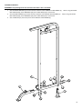
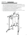
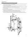
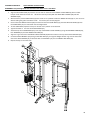
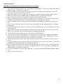
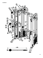
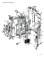
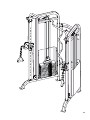
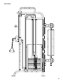
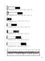
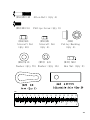
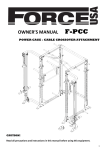
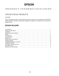
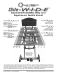
OWNER’S MANUAL F-FTS
FUNCTIONAL TRAINING SYSTEM
CAUTION!
Read all precautions and instructions in this manual before using this equipment.
1
ASSEMBLY MANUAL FOR:
FORCE USA FUNCTIONAL TRAINING SYSTEM F-FTS
BEFORE YOU START
Remove all parts from the packaging and separate and count each various component to ensure everything has been
correctly provided.
Follow the instructions and consult both the individual assembly pages and the overall expanded views of the
equipment
It is the owner’s responsibility to ensure that all users of this unit have read the owner’s manual and are familiar with
the safety precautions.
SAFETY PRECAUTIONS
•
•
•
•
•
•
•
•
•
•
•
•
•
•
Highly recommended for two or more people to assemble the equipment to avoid injury.
Assemble the equipment on a flat level surface.
Consider placing a mat under the equipment to protect your floor.
Wear appropriate footwear and clothing during assembly and use.
Only tighten nuts and bolts by hand until the whole equipment is assembled
Do not allow children and pets to be unsupervised around the assembly or usage of this equipment.
Ensure all parts are in full working order before use.
Only one person should use the machine at any one time.
Do not use the equipment outdoors or around water.
Keep hair, fingers or clothing away from moving parts.
Only use attachments recommended by the manufacturer.
Never operate if any parts are not functioning correctly.
Always correctly stretch and warm up before using the equipment.
Stop immediately if your experience any pain, dizziness or nausea. See a doctor at once.
PLEASE NOTE: Descriptions of pieces as LEFT and RIGHT are from the point of view of standing behind th
equipment facing towards the front.
BEFORE STARTING ANY EXERCISE PROGRAM, CONSULT YOUR DOCTOR. ESPECIALLY IF YOU ARE OVER
THE AGE OF 35 OR HAVE PRE-EXISTING HEALTH PROBLEMS.
READ ALL INSTRUCTIONS BEFORE ASSEMBLING OR USING ANY FITNESS EQUIPMENT.
FORCE USA FITNESS EQUIPMENT ASSUMES NO RESPONSIBILITY FOR PERSONAL INJURY OR PROPERTY
DAMAGE SUSTAINED BY OR THROUGH THE USE OF THIS PRODUCT.
SAVE THESE INSTRUCTIONS.
2
F-FTS PARTS LIST
KEY NO.
DESCRIPTION
SPEC
Q'ty
1
Weight Stack Frame
2
2
Front Support
2
3
Rear Support
2
4
Vertical Frame
2
6
Left Sliding Block
1
7
Right Sliding Block
1
8
Swivel Pulley Bracket
2
9
Rear Upper Frame
1
10
Rear Lower Frame
1
11
Chin-up Bar
1
12
Guide Rod
13
Pulley Bracket
2
14
Lat Bar
1
15
Lat Bar
1
16
Bar Handle
4
17
Poster Frame
1
18
Weight Stack Cover
750×440×1.2
2
19
Selector Stem
189×79×33
2
20
Weight Plate
366×102×25
28
21
Selector Rod
φ25×450
2
22
Adjustable Single Handle
23
Cable
L=6695mm
2
24
Bracket
140×50×3
4
25
Spring
φ18×φ2.5×150
1
26
Bushing
φ38×φ9×8
4
27
Lock Knob
28
Hook
29
Weight Selection Pin
30
Bushing
φ25×1636
4
2
2
φ8
2
2
φ18×φ14×φ10.2×12
4
3
31
Rivet
φ4×10
8
32
Handle Grip
φ24×φ18×227
2
33
Sleeve
□60×□45
4
34
Pulley
φ95
2
35
Pulley
φ96
6
36
Pulley
φ75×25
8
37
End Cap
PT40×80
2
38
Rubber Bumper
φ62×φ24.5×25
4
39
Bushing
φ38×φ34×φ27×26
10
40
End Cap
□25
4
41
Poster Board
800×400×3
1
42
Ankle Strap
43
Adjustable Axle
φ24×75
2
44
Carriage Bolt
M10×60
12
45
Allen Bolt
M8×25
4
46
Allen Bolt
M10×20
4
47
Hex Nut
M12
2
48
Allen Bolt
M10×45
16
49
Allen Bolt
M10×55
8
50
Carriage Bolt
M10×65
2
51
Allen Bolt
M10×90
4
52
Allen Bolt
M8×40
4
53
Allen Bolt
M8×16
8
54
Aircraft Nut
M10
40
55
Aircraft Nut
M8
4
56
Washer
10
70
57
Washer
8
16
58
Allen Bolt
M10×65
2
59
Pulley Bushing
φ22×φ10.2×12.5(zn)
4
Allen Wrench
5#
1
Allen Wrench
6#
1
1
4
ASSEMBLY DIAGRAM 1:
REMEMBER: Only hand tighten all nuts and bolts until whole F-FTS is assembled
1.
2.
3.
Slot the FRONT SUPPORTS (2) into the sockets at the front of the WEIGHT STACK FRAMES (1). Attach using two ALLEN
BOLT M10X55 (49), three WASHER10 (56) and one NUT M10 (54) on each frame.
Slot the REAR SUPPORTS (3) into the sockets at the back of the WEIGHT STACK FRAMES (1). Attach using two ALLEN
BOLT M10X55 (49), three WASHER10 (56) and one NUT M10 (54) on each frame.
Slot an END CAP (37) into the top front of the WEIGHT STACK FRAMES (1)
5
ASSEMBLY DIAGRAM 2:
USE A PARTNER TO HELP IN THIS
REMEMBER: Only hand tighten all nuts and bolts until whole F-FTS is assembled
1.
2.
3.
4.
5.
6.
7.
8.
Stand up the assembled frames. Use assistance holding the frames as you attach the rear supports.
Align the REAR LOWER FRAME (10) with the lower set of holes on the back of the WEIGHT STACK FRAMES (1).
Attach using two CARRIAGE BOLT (44), one BRACKET (24), two WASHER10 (56) and two AIRCRAFT NUT M8 (54)
on each side. Ensure the REAR LOWER FRAME (10) is orientated correctly
Assemble the POSTER FRAME (17) by attaching the POSTER BOARD (14) to the POSTER FRAME (17) with eight RIVET
(31). Put an END CAP (59) on the corners of the frame. (Skip this step if already pre-assembled)
Insert a BUSHING (39) into the socket on the REAR UPPER (9) and REAR LOWER FRAME (10)
Insert a SPRING (25) into the socket on the top of the REAR LOWER FRAME (10).
Slot the POSTER FRAME (17) down into the tube socket on the top of the REAR LOWER FRAME (10)
Slot the REAR UPPER FRAME (9) into the top of the POSTER FRAME (17)
Attach the REAR UPPER FRAME (9) to the WEIGHT STACK FRAMES (1) using two CARRIAGE BOLT (44), one BRACKET
(24), two WASHER10 (56) and two AIRCRAFT NUT M8 (54) on each side.
6
ASSEMBLY DIAGRAM 3:
REMEMBER: Only hand tighten all nuts and bolts until whole F-FTS is assembled
1.
Assemble the SLIDING BLOCKS (7+8) by attaching a HANDLE GRIP (32) to the handle. Slot a SLEEVE (33) into the top and
bottom of the block. (Skip this step if already pre-assembled)
2. Assemble the SWIVEL PULLEY BRACKETS (8) by slotting a BUSHING (30) into the top and bottom of its connecting point.
(Skip this step if already pre-assembled)
3. Attach a SWIVEL PULLEY BRACKET (8) to the RIGHT SLIDING BLOCK (7) and the LEFT SLIDING BLOCK (6) using an ALLEN BOLT
M10X90 (51), two WASHER10 (56) and an AIRCRAFT NUT M8 (54) each bracket.
4. Slide the completed block and bracket (8 + 7) onto the base of the VERTICAL FRAME (4). Ensure the frames and brackets
are correctly orientated.
5. Attach the LOCK KNOBS (27) into the inner-side socket on the RIGHT SLIDING BLOCK (7) and the LEFT SLIDING BLOCK(6).
Lock the block and bracket into a hole on the frame.
6. Align the base of the VERTICAL FRAMEs (4) with the bracket at the front of the FRONT SUPPORTs (2). Attach with a
CARRIAGE BOLT (50), a WASHER10 (56) and an AIIRCRAFT NUT M8 (54) on the frames.
7. Align the CHIN-UP BAR (11) with the bolt holes on the top of the WEIGHT STACK FRAME (1).
8. Attach from underneath, connecting the VERTICAL FRAMES (4) to the WEIGHT STACK FRAME (1) and the CHIN-UP
BAR (11) using two CARRIAGE BOLT M10X60 (44), two WASHER10 (56) and two AIRCRAFT NUT M10 (54) on each frame.
7
ASSEMBLY DIAGRAM 4:
USE A PARTNER TO HELP IN THIS
REMEMBER: Only hand tighten all nuts and bolts until whole F-FTS is assembled
1.
2.
3.
4.
5.
6.
7.
8.
9.
Align the two GUIDE RODS (12) with the correct holes on the base of the WEIGHT STACK FRAME (1) with a rubber
bumper under the base of each rod. Attach the rods very loosely with two ALLEN BOLT M10X20 (46) and two
WASHER10 (56)
With assistance, tilt the GUIDE RODS (12) back a little so it is possible to slide the WEIGHT PLATES (20) on, one at a time
without taking the guide rods off the frame. Ensure they are correctly aligned
Once all fourteen WEIGHT PLATES (20) have been slid onto the GUIDE RODS (12), slide the SELECTOR STEM (19) onto
the GUIDE RODS (12) so it slots down into the weight stack.
Tilt the GUIDE RODS (12) back so they are vertical and in position to be attached.
Tighten the bolts at the base of the GUIDE RODS (12)
Attach the top of the GUIDE RODS (12) to the top of the WEIGHT STACK FRAME (1) using two ALLEN BOLT M8X40 (52),
four WASHER8 (57) and two AIRCRAFT NUT M8 (55)
Align the ring on the end of the WEIGHT SELECTION PIN (29) with the socket on the top of the SELECTOR STEM (19).
Screw the PULLEY BRACKET (13) through a HEX NUT M12 (47), through the weight selector ring and into the socket.
Secure the SELECTOR ROD (21) underneath with an ALLEN BOLT (51) and an AIRCRAFT NUT M10 (54).
Repeat all steps on the other side.
8
ASSEMBLY DIAGRAM 5:
REMEMBER: Only hand tighten all nuts and bolts until whole F-FTS is assembled
1.
Align a PULLEY 96 (35) with the bottom hole on the SWIVEL PULLEY BRACKET (8). Attach using an ALLEN BOLT (48), two
WASHER10 (56) and an AIRCRAFT NUT M10 (54)
2. Position the CABLE (23) with the stopper end coming out the front of the SWIVEL PULLEY BRACKET (8) and the cable
running over the top of the installed PULLEY 96 (35)
3. Align another PULLEY 96 (35) so the CABLE (23) runs under and up the back of the pulley inside the SWIVEL PULLEY
BRACKET (8). Attach using an ALLEN BOLT (48), two WASHER10 (56) and an AIRCRAFT NUT M10 (54)
4. Draw the CABLE (23) upward and through the hole at the front of the VERTICAL FRAME (4)
5. Position a PULLEY 95 (34) in the front bracket so the CABLE (23) runs over the top. Attach the PULLEY 95 (34) using an
ALLEN BOLT (58), two WASHER10 (56) , two Pulley Bushing (59)and an AIRCRAFT NUT M10 (54)
6. Draw the CABLE (23) along the underside of the top of the WEIGHT STACK FRAME (10 and through the bracket at the
rear.
7. Position a PULLY 75X25 (36) in the bracket and attach with an ALLEN BOLT (48), two WASHER10 (56) and an AIRCRAFT
NUT M10 (54)
8. Draw the CABLE (23) down through the rear hole at the top of the GUIDE RODS (12) to the PULLEY BRACKET (13) on top
of the weight stack.
9. Align a PULLEY 75X25 (36) in the PULLEY BRACKET (13) so the cable runs behind, under and up the front of the pulley.
Attach using an ALLEN BOLT (48), two WASHER10 (56) and an AIRCRAFT NUT M10 (54)
10. Draw the CABLE (23) upward thought the front hole between the GUIDE RODS (12).
11. Align and attach two PULLEY 75X25 (36) into the two bracket holders near the top of the WEIGHT STACK FRAME (1)
using an ALLEN BOLT (48), two WASHER10 (56) and an AIRCRAFT NUT M10 (54) in each. The CABLE (23) should run
forward over the top of the pulleys and down the front side of the frontal pulley.
12. Draw the CABLE (23) straight down and through the hole at the base of the face, towards the front and through the
bracket.
13. Align a PULLEY 96 (35) in the bracket so the CABLE (23) runs underneath and up the front of the pulley. Attach using
ALLEN BOLT (48), two WASHER10 (56) and an AIRCRAFT NUT M10 (54)
14. Screw the end of the CABLE (23) into the socket of the ADJUSTABLE AXLE (43). Attach the other end of the ADJUSTABLE
AXLE(43) between the bracket on the back of the SLIDING BLOCK (6+7) using an ALLEN BOLT M10X45(48), two
WASHER10 (56) and an AIRCRAFT NUT M10 (54)
15. Connect a HOOK (28) to the front end of the CABLE (23). Connect the HOOK (28) to an ADJUSTABLE SINGLE HANDLE
(22)
16. Repeat all steps on the other side.
9
DIAGRAM 5:
10
ASSEMBLY DIAGRAM 6:
REMEMBER: Only hand tighten all nuts and bolts until whole F-FTS is assembled
1.
2.
3.
Assemble the LAT BAR (14+15) by sandwiching a BAR HANDLE (16) between two BUSHINGS (39), sliding it onto the end
of the bars and attaching using a BUSHING (26) a WASHER8 (57) and an ALLEN BOLT (45). Repeat for the other ends.
(Skip this step if already pre-assembled)
Slot the two LAT BARS (14 +15) into the clips at the back of the REAR UPPER FRAME (9) and THE REAR LOWER FRAME
(10)
Align the WEIGHT STACK COVER (18) with the four sockets on the outside of the WEIGHT STACK FRAME (1). Attach
each corner with a ALLEN BOLT (53) and a WASHER8 (57).
42
11
OVERALL EXPLODED VIEW
56
54
9
54
56
14
15
40
11
40
39
36
54
56
59
34
37
59
56
58
44
35
51
48
54
56
30
56
22
57 53
56
54
48
27
33
32
50
56
2
35
54
56
54
13
56
48
47
44
57
53
54
56
48
56
45
36
24
56
54
35
56
12
57
43
28
1
53
18
7
30
44
57 53
53 56
38
57
56
54
40
25
39
37
19
1
51
49
23
54
49
41
31
54
10
21 56
56
17
39
16
39
26
57
55
24
56
54
4 44
33
57
52
57
23
8
48
56
36
18
3
6
8
46
20
28
22
42
3
29
4
2
12
13
SIDE-VIEW
14
0h &DUULDJH%ROW˄4W\˅
0h &DUULDJH%ROW˄4W\˅
0h $OOHQ%ROW˄4W\˅
0h $OOHQ%ROW˄4W\˅
0h $OOHQ%ROW˄4W\˅
0h $OOHQ%ROW˄4W\˅
0h $OOHQ%ROW˄4W\˅
PP
ą
ą
ą
ą
ą
ą
15
0h
$OOHQ%ROW˄4W\˅
0h
3KLOLSV6FUHZ˄4W\˅
0
$LUFUDIW1XW
˄4W\˅
0
$LUFUDIW1XW
˄4W\˅
¶
¶
3XOOH\%XVKLQJ
˄4W\˅
0
:DVKHU˄4W\˅ :DVKHU˄4W\˅
+H[1XW˄4W\˅
PP
ą
ą
ą
ą
ą
ą
16
WARRANTY
LIFETIME WARRANTY ON FRAME
2 YEARS ON CABLES AND PULLEYS
Force USA, the Trusted Name in Strength Equipment™ was designed to be the best value strength
equipment for home use and proudly set the benchmark for our home use equipment around the world.
Offering one of the best warranties on the market for your peace of mind, each piece of Force USA
strength equipment is hand crafted for quality and we use state-of-the-art production methods for our
entire range. The Force USA range of strength equipment carries a Lifetime Structural Warranty along
with 2 years cover on all cables and pulleys. This warranty applies to first owners and does not cover
second hand equipment or re-sold equipment. This Force USA warranty covers only failures due to
defects in structural, cables and pulleys and workmanship that occur during normal home use. It will not
cover damage that occurs in transport/delivery or failure due to misuse, abuse, neglect, mis-application,
alteration or improper assembly of the product. This warranty does not cover the use or failure of equipme
in studio commercial applications. The replacement or repair provided for under the Force
USA warranty is the responsibility of the user and the customer will be responsible for any freight
charges applicable. Force USA will not be liable for any consequential damages or for breach of any
implied warranty on the range of Force USA strength equipment. Force USA reserves the right to provide
reconditioned parts and/or to request a return and repair existing defective parts on the Force USA
product.
VorTex by Force USA is a commercial grade upholstery used for all Force USA equipment. We use a high
grade commercial vinyl with rip-stop mesh backing which helps prevent rips and tears. Force USA, the
Trusted Name in Strength Equipment™ was designed to be the best value strength equipment for home
use and proudly set the benchmark for our home use equipment around the world.
17
F-FTS
Box one˖
2×part 4ˈ
1x part 11ˈ
1×part 14ˈ
1×part 15ˈ 4×part 12ˈ
2×part 1ˈ
2x part 18ˈ
1×part 6ˈ
1×part 7
2×part 21ˈ
1x part 42ˈ
2×part 22ˈ
2×part 34ˈ 1×part 9ˈ
2×part 8ˈ
1x part 10ˈ
6×part 35ˈ
1×part 25ˈ 2×part 27ˈ
2×part 29ˈ
4x part 38ˈ
2×part 19ˈ
8×part 36ˈ 2×part 2ˈ
4×part 24ˈ
2x part 3ˈ
2×part 13ˈ
2×part 23ˈ 2×part 2ˈ
Box two˖
Parts bag 1of 2ˈParts bag 2of 2
Box three˖
7×part 20
Box four˖
7×part 20
Box five˖
7×part 20
Box six˖
7×part 20