1
SiteNet® Integrator
SNMP Communications
for Integrated Products
Load Control Module
SNMP Remote Control
of Critical Loads
USER MANUAL
English
IMPORTANT SAFETY INSTRUCTIONS
SAVE THESE INSTRUCTIONS
This manual contains important safety instructions that should be followed during
the installation and maintenance of this product. Please read this manual
thoroughly before attempting to install or operate this product.
This equipment can be installed and operated by individuals without previous
training.
1.
Sitenet Integrators and Load Control Modules (LCM) are available for
120VAC and 230VAC supply voltages/loads. Please verify that this model
matches your AC mains/ load voltage requirements.
For UPS installation requirements, refer to user manual supplied with the
UPS.
2.
This equipment is designed for Commercial/Industrial use only. Liebert
Corporation neither recommends nor knowingly sells this product for use in
critical life support applications.
The LCM 230VAC models are not supplied with an input power lead for
connection from the LCM to the UPS output. Use the output power lead with
your UPS to connect the UPS to the LCM power input.
3.
The LCM must be grounded / earthed at all times during operation. Connect
only to the UPS output or a mains supply socket outlet with an earth
connection. A means of disconnection of the mains supply should be within
2 metres of the UPS/LCM installation..
4.
To reduce the risk of electric shock, do not remove the covers, there are no
user-serviceable parts inside. For service, contact a qualified technician.
To prevent the risk of fire or electric shock, install the
UPS/LCM/Integrator in a temperature and humidity controlled room, free
of conductive contaminants.
5.
The UPS output receptacles providing conditioned power to the LCM module
must be capable of supplying at least 10 amperes to the 230V LCM module
(12 amperes for 120V modules) plus a supply of 50 mA for the Integrator
module power supply.
6.
The total load earth leakage current of the installation comprising the UPS,
LCM and your connected load must not exceed 3.5 milli-amperes for 230v
models (5.0 milliamperes for 120V supplies). Where this may be exceeded
the LCM module should be provided with a supplementary bonding
conductor to ground( earth). For further advice contact your dealer.
7.
The installation relies on your building wiring overcurrent protection, which
must not be rated more than 20 amperes.
8.
When using the communication features on the UPS, ensure the cabling
connected to the DB9 communication port or the network connection are
kept separated by 25mm from the power leads to the UPS input and output.
2
Information for 230V users
Electromagnetic Compatibility: The 230V LCM/Integrator combination complies
with EMC Directive 89/336/EEC and the published technical standards.
Continued compliance requires installation in accordance with these instructions
and the use of manufacturer approved accessories only.
WARNING:
This is a Class A product. In a domestic environment, this product may cause
radio interference , in which case, the user may be required to take additional
measures.
Information for 120V users
The 120V LCM/Integrator combination complies with the limits for a Class A
digital device, pursuant to Part 15 of FCC rules. These limits provide reasonable
protection against harmful interference in a commercial environment. This
device generates, uses, and radiates radio frequency energy and, if not installed
and used in accordance with the instruction manual, may cause harmful
interference to radio communications. Operating this device in a residential area
is likely to cause harmful interference, which the user must correct at his own
expense.
CAUTION:
Although your LCM/Integrator has been designed and manufactured to assure
personal safety, improper use can result in electrical shock or fire. To ensure
safety, please observe the following rules:
Turn off and unplug your LCM/Integrator before cleaning. Do not use liquid
or aerosol cleaners. A dry cloth is recommended to remove dust from the
surface of your modules.
Do not install or operate in or near water.
Do not place on an unstable cart, stand, or table.
Do not place under direct sunlight or close to heat emitting sources.
Do not place power cords in any area where it may get damaged by heavy
objects.
Follow all warnings and instructions marked on the LCM/Integrator. Do not
attempt to service the LCM/Integrator, as it has no user-serviceable parts
inside. Refer all repairs to qualified service personnel.
ATTENTION:
Turn off and unplug your installation from the receptacles and contact qualified
service personnel if:
If any power cord or plug is damaged.
Liquid has been spilled on the modules.
The fuse/circuit breakers blows/trip frequently.
The installation does not operate correctly even when the user follows the
operating instructions.
CONDITIONS OF USE:
Your UPS provides conditioned power to the LCM and your connected
equipment. Maximum load must not exceed that shown on LCM rating label. If
uncertain, consult your distributor or Liebert.
3
4
INTRODUCTION
Congratulations on the purchase of the Liebert SiteNet® Integrator
Environmental Interface with optional Load Control Module. The SiteNet®
Integrator monitors and controls various network devices such as UPS Systems,
Environmental Control Systems, and Site Security Devices. Two output contact
closures control external devices.
With an optional SiteNet® Integrator Load Control Module (LCM), the Integrator
(Ethernet version) allows remote network control of up to six connected loads.
The SiteNet® Integrator uses Simple Network Management Protocol (SNMP) to
communicate status information contained in a Management Information Base
(MIB) to your Network Management System (NMS). In addition to the UPS MIB,
the Integrator also monitors data and environmental control conditions (see
"Integrator Environmental MIB").
Basic SiteNet® Integrator features include:
Ethernet or Token Ring compatibility
Power source redundancy with two separate power inputs
Up to ten (10) digital inputs
Two temperature/humidity sensor inputs
One thermistor sensor input
Audible alarms
Two programmable relay outputs
Front panel status and output LED indicators
Programmable alarm traps.
Customize audible alarms, output relays, LED’s, and traps to control how the
Integrator communicates various information.
Basic LCM Module features include:
Six separately controllable output receptacles
Output status and main power LED indicators
Adjustable start-up delay for sequential power-up
Ethernet compatibility
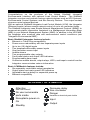
GLOSSARY OF SYMBOLS
Attention
See user manua l
Decrease delay
time clockwise
No user serviceable
parts inside
Danger
Receptacle power on
Input
Hazardous electrical parts inside
On
Output
Standby
5
INTEGRATOR INSTALLATION
SiteNet® Integrator installation requires these items:
RS-232 (Integrator to UPS) cable-optional (Liebert part no. 141088P1)
RS-232 Integrator to (PC) terminal cable with adapter (Liebert part nos.
146618P1 and 146617P1 respectively)
SiteNet® Integrator User’s Manual
Diskettes containing UPS MIBs and the Integrator Environmental MIB in
DOS and TAR (UNIX) formats.
Ferrite Beads (included, Liebert part no. 146736P1 for .25” bead, 146735P1
for .5” bead)
Clamp bead with cable enclosed
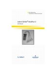
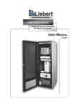
Ferrite Bead Installation
Install the two ferrite beads on
the incoming power supply and
network connection cables prior
to SiteNet® Integrator operation.
Open the smaller ferrite bead.
Wrap the main power supply
cable around the ferrite bead
once and clamp the bead with the
power supply cable enclosed.
Open the larger ferrite bead.
Place the network cable inside
the ferrite bead, and clamp the
bead with the network cable
enclosed. Clamp the ferrite bead
near the connector that mates
with the Integrator.
Wrap cable once
around ferrite bead
Temperature / Humidity Sensor Wiring Instructions
There are two temperature / humidity sensor options available, differentiated only
by cable size. Both cables provide temperature (32° F - 140° F) and humidity
(20% to 80 % RH) monitoring.
141604G1L: Sensor package with 15 ft. cable
141605G1L: Sensor package with 30 ft. cable
Wiring the Temperature / Humidity Sensor to the Integrator
1. The Temperature / Humidity Sensor has four wires – green, black, white,
red. A braided, silver shield is also included to ground to the Integrator.
2. Cut wires to remove the adapter and strip the end to expose the metal.
3. Wire the Temperature / Humidity module to the Integrator as follows:
Green
Black
4.
→ T
→ H
White
Red
→ +
→ -
Connect the braided shield to one of the two ground screws on the
Integrator. Assure that the Integrator is also properly grounded.
6
7
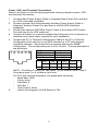
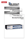
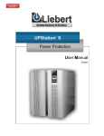
Power, UPS, and Terminal Connections
Refer to the figure on the following page when making Integrator power, UPS,
and terminal connections.
1.
2.
3.
4.
5.
Connect Main Power Supply Cable to Integrator Main Power Port and then
to a UPS-controlled receptacle.
Connect optional (but recommended) Auxiliary Power Supply Cable to
Integrator Auxiliary Power Port and then to a NON-UPS-controlled
receptacle.
Connect the optional UPS DB-9 Output Cable to the Liebert UPS Output
Port and then to the UPS serial port.
Connect all Liebert or customer supplied input devices (such as sensors or
switches) and output relays required for your installation.
Connect the PC or Terminal Configuration Cable to the PC or Terminal
Configuration Port and then to an ASCII terminal or a PC with terminal
emulation software. Disconnect this connection after proper SNMP
configuration. The configuration port is a RJ-12 jack. The wire descriptions
are as follows:
TxD
wire 2
RxD
wire 3
SG
wire 5
Not Connected wires 1,4,6
123456
Pin 2
Pin 3
Pin 5
6.
TxD
RxD
Gnd
↔
↔
↔
RxD
TxD
Gnd
Pin 3
Pin 2
Pin 5
NOTE: If building or using your own cable, do not connect wires 1 and 6.
Grounding wires 1 or 6 creates a fault error.
For PC's with terminal emulation, set parameters as follows:
Baud Rate: 9600
Parity: None
Data Bits: 8
Stop Bit: 1
Flow Control: None
Switch the Integrator On/Off Switch to ON.
8
9
R
R
POW ER JACK
SiteNet
Integrator
POW ER JACK
SiteNet
Integrator
POWER
SUPPLY
POWER
SUPPLY
AUX
AUX
INPUT: 9VDC 1A
MAIN
INPUT: 9VDC 1A
MAIN
RS-232
DB-9P
UPS
UPS
Port
RS-232
DB-9P
UPS
UPS
Port
CIRCULAR
DIN
AUX MOD
CIRCULAR
DIN
C -NC- NO
C -NC- NO
28V, 1A
C -NC -NO
RELAY OUTPUTS
K1
K2
28V, 1A
C -NC -NO
AUX MOD RELAY OUTPUTS
K1
K2
1
1
2
2
4
5
6
7
8
DRY-CONTACT INPUTS
9
10
-
T H +
MODU LE2
4
5
6
7
8
DRY-CONTACT INPUTS
9
10
TEMP
SEN SOR
-
T H +
MODU LE2
-
TEMP
SEN SOR
TEMP/HUM INPUTS
M OD ULE1
T H +
ALL OUTPUTS: CLASS 2. ALL INPUTS: CLASS 2.
3
ETHERNET
-
RS-232
RJ-12
CHASSIS
GROUND
RS-232
RJ-12
CONFIGURATION
PORT
Token Ring
UTP Network
Port
Ethernet UTP
Network Port
UTP
RJ-45
STP
DB-9S
(TOKEN R ING ON LY)
UTP
RJ-45
NETWORK CONNECTION
STP
DB-9S
(TOKEN R ING ON LY)
NETWORK CONNECTION
Token Ring
STP Network
Port
Configuration
Port
CHASSIS
GROUND
CONFIGURATION
PORT
Configuration
Port
TEMP/HUM INPUTS
M OD ULE1
T H +
ALL OUTPUTS: CLASS 2. ALL INPUTS: CLASS 2.
3
TOKEN RING
INTEGRATOR NETWORK PORTS
LCM INSTALLATION
LCM installation requires these items:
Installed SiteNet® Integrator
8-pin DIN Integrator to LCM cable
This SiteNet® Integrator Load Control Module User’s Manual
A suitable Uninteruptible Power Supply (UPS) rated:
120V, 12 Amps for the 120V LCM
230V, 10 Amps for the 230V LCM
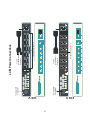
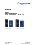
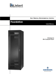
LCM, Integrator and Power Connections
Refer to the figure on the following page when making LCM power connections.
1. Plug the AC power cord into the LCM module.
2. Connect the 8-pin DIN cable to the LCM and Integrator.
Receptacle Time Delay Adjustment & Load Connection
Powering up the LCM sequentially activates the switched receptacles (one
through six) with a time delay between each activation. The time delay ranges
from .1 to 7 seconds.
1. To test interval time, press LCM ON switch before plugging in loads. Note
the time between the activation of each light (one through six). Press switch
again to turn off.
2. Insert a small screwdriver into the time delay adjustment, just left of the main
power switch, to adjust the amount of time between receptacles. Turn
clockwise to decrease and counterclockwise to increase the receptacle time
delay.
3. Plug loads into LCM receptacles. Consider time delays if you skip
receptacles. Press On switch to confirm appropriate time delay.
NOTE: If adjustment is turned beyond maximum setting, delay will return to
minimum setting.
CAUTION: Total load must not exceed 12 Amps (10 Amps for 230V). Total
leakage current of UPS and connected loads must not exceed 5mA (3.5 mA for
230V).
10
11
120 V
230 V
DIN
Input
1
Site Ne t In te grator LCM
R
1
To Circular DIN
on Integrator
Load
Control
Module
SiteNet Integrator LCM
R
To Circular DIN
on Integrator
2
2
3
3
4
4
5
5
6
6
R
R
Power
MAIN
CIRCUIT
BREAKER
1
1
O
OFF
ON
I
1
2
3
2
3
3
TOTAL OU TPUT: 15 AMPERES
4
4
5
2
1
5
3
4
6
4
5
Switched Receptacles 1-6
3
4
Switched Receptacles 1-6
2
To UPS
Controlled
Receptacle
1
2
To UPS
Controlled
Receptacle
LCM Power Connections
5
6
5
6
6
CONTROL
OFF
ON
6
1 5 A MP M AX.
INPUT POWER:
230 VAC
10A
50/60
HZ.
50-60
HZ.
100-120
VAC
SNMP AGENT CONFIGURATION
1.
Refer to the figure on the following page when following the Integrator
network connection instructions below.
Ethernet: The Integrator Ethernet Network Port is an RJ-45 jack for an
Ethernet unshielded twisted pair (UTP) 10BASET connection.
Token Ring: The Integrator allows two possible Token Ring connections Use the STP DB-9S jack for a shielded twisted pair connection; use the UTP
RJ-45 jack for an unshielded twisted pair connection. Connect the usersupplied network cable (with ferrite beads installed) to the appropriate
network port and then to the network.
2.
Verify or manually enter the SiteNet® Integrator IP address and Net Mask.
All Ethernet Options support the BOOTP function in SNMP, which provides
the Integrator's IP address, Net Mask, and Default Router. The SNMP
Agent will request a TFTP file with additional instructions on assigning
addresses supported by BOOTP. Refer to the sample TFTP file at the end
of this manual and the BOOTP and TFTP server documentation for server
configuration.
NOTE: Turn caps lock OFF. Type configuration entries in lowercase.
3.
The BOOTP feature comes factory-enabled. If your network does not run
BOOTP and TFTP servers, disable the BOOTP function (BootP mode: off),
and manually enter Integrator network configuration information. For manual
entry, press Enter after your ASCII terminal displays the message "BOOTP
Server has not responded yet". Allow at least 60 seconds for the system
response, "Do you wish to go to the configuration menu? (Y/N)". Press
"y", and the Configuration Menu displays with pre-loaded factory defaults
(see Ethernet and Token Ring menus on the page following the Integrator
Network Ports diagram).
4.
Press "i" to enter the IP Address. Press "m" to enter the Net Mask. Press
"b" to turn BootP mode off. Press the appropriate keys associated with any
other parameter you wish to enter (see steps 6 &7). When finished, Press
"x" to permanently save the settings and exit the configuration menu. The
SNMP Agent automatically restarts with the new settings.
NOTE: BootP mode must be off to manually enter settings. If on, BootP
erases any new settings when the user attempts to save them.
If your network begins running BOOTP and TFTP servers after you disabled
the BootP mode and manually entered the Integrator configuration settings,
reassign these settings through BOOTP by configuring the BOOTP and
TFTP servers and enabling the BOOTP function (BootP mode: on).
5.
Run the SNMP software (it runs automatically after saving manually entered
settings). If IP Address and Net Mask are already configured, the software
runs automatically at power-up.
12
13
To UPS
To UPS
Controlled
Receptacle
R
DB-9 or
DB-25
Connector
POWER JACK
SiteNet
Integrator
INPUT: 9VDC 1A
AUX
DB-9 UPS
Output Cable
POWER
SUPPLY
MAIN
Ferrite
Bead
RS-232
DB-9P
UPS
CIRCULAR
DIN
C-NC-NO
28V, 1A
C-NC-NO
AUX MOD RELAY OUTPUTS
K1
K2
1
2
4
5
6
7
8
DRY-CONTACT INPUTS
9
10
T H +
-
MODULE1
T H +
MODULE2
-
TEMP
SENSOR
TEMP/HUM INPUTS
PC or Terminal
Configuration
Cable
ALL OUTPUTS: CLASS 2. ALL INPUTS: CLASS 2.
3
To PC or
Terminal
To NON UPS
Controlled
Receptacle
RS-232
RJ-12
Network
Cable
CHASSIS
GROUND
CONFIGURATION
PORT
Integrator Power, UPS, and Terminal Connections
STP
DB-9S
UTP
RJ-45
NETWORK CONNECTION
(TOKEN RING ONLY)
Configuration Menu
Press the key to modify the entry
-d
sysDescr:
Uninitialized
-l
sysLocation:
Uninitialized
-o
sysContact:
Uninitialized
-n
sysName:
Uninitialized
-a
snmpEnableAuthenTraps:
Disabled
-i
IP Address:
0.0.0.0
-m
Net Mask:
0.0.0.0
-r
Default Route
0.0.0.0
-c
Display/Modify Communities
-t
Display/Modify Trap Communities
-b
BootP mode: on
-q
Quit without saving configuration
-x
Exit, saving configuration to nonvolatile storage
press a key:
Ethernet Configuration Menu
Configuration Menu
Press the key to modify the entry
-d
sysDescr:
Uninitialized
-l
sysLocation:
Uninitialized
-o
sysContact:
Uninitialized
-n
sysName:
Uninitialized
-a
snmpEnableAuthenTraps:
Disabled
-y
Ring Speed
16 Mb
-i
IP Address:
0.0.0.0
-m
Net Mask:
0.0.0.0
-r
Default Route
0.0.0.0
-c
Display/Modify Communities
-t
Display/Modify Trap Communities
-b
BootP mode: on
-q
Quit without saving configuration
-x
Exit, saving configuration to nonvolatile storage
press a key:
Token Ring Configuration Menu
14
6.
To modify an already configured SNMP agent, press "c" to access the
SNMP Agent's configuration menu loaded with the current configuration
settings (see Ethernet and Token Ring menus on previous page). Press the
key associated with the parameter you wish to enter or modify, then type the
desire value. Press Return when finished. Here are short descriptions of
the first eight parameters:
sysDescr, sysLocation, sysContact, and sysName are text strings
that give general information.
snmpEnableAuthenTraps enables or disables Authentication Failure
trap messages to manager stations. Enter "e" to enable or "d" to
disable, then press Return.
Ring Speed (Token Ring only) specifies information transfer speed.
IP Address contains the SNMP Agent's IP address in dotted decimal
notation (e.g. 126.10.200.3). Type the desired address, then press
Return.
Net Mask contains the Net Mask in dotted decimal notation
(e.g. 255.255.128.0). Type the desire Net Mask, then press Return.
Default Route contains the IP Address of the network's default route in
dotted decimal notation. Type the desired IP address, then press
Return.
7.
To configure communities, press "c" to access the Communities
Configuration sub-menu loaded with the current communities configuration:
Communities Configuration
#
IP Address
Priv
0:
198.30.160.58
write
1:
198.160.30.2
write
Community
public
Supervisor
Enter the number of the community to modify/delete, "a" to add, or "e" to exit
Command:
Communities Configuration Sub-Menu
Enter "a" to add a new community. Respond to the on-screen prompts.
Enter community number from the "#" column to modify or delete a
community. At the prompt, enter "d" to delete, or "m" to modify the
community. When adding or modifying entries, respond to the on-screen
prompts:
IP Address - Enter in dotted decimal notation the IP address of the
manager station authorized to use this community.
Privileges - Enter "r" for Read-Only, "w" for Read-Write.
Community String (Name) - Enter the community name. This entry is
case-sensitive; be sure to enter it exactly as entered in the NMS.
Enter "e" to exit the sub-menu.
15
8.
To configure trap communities, press "t" to access the Trap Communities
Configuration sub-menu loaded with the current trap communities
configuration:
Trap Communities Configuration
#
IP Address
0:
198.30.160.58
1:
198.160.30.2
Community
public
Supervisor
Enter the number of the community to modify/delete, "a" to add, or "e" to exit
Command:
Trap Communities Configuration Sub-Menu
With the exception of the "Privileges" entry, the Trap Communities Configuration sub-menu operates similarly to the Communities Configuration submenu. Set the IP Address to the Network Management Station's IP
Address. When finished, enter "e" to exit the sub-menu.
9.
Enter "b" to turn BootP mode ON or OFF. NOTE: BootP mode must be OFF
to modify configuration settings. If on, BootP erases the settings when the
user saves the configuration.
10. Exit the configuration mode:
Press "q" to exit without saving the modifications. The system
immediately returns to the SNMP Agent.
Press "x" to save the new configurations to flash EPROM. The system
automatically restarts the SNMP Agent using the new settings.
After exiting, you may return to configuration mode by pressing "c".
UPS & INTEGRATOR MIB COMPILATION
The enclosed diskettes contain MIB files your NMS needs to receive information
from the UPS through SNMP communications. The files are in both DOS and
TAR (UNIX) formats for your convenience.
Different UPS models require slightly different versions of the SNMP MIB. The
README.TXT file gives the correct MIB file to use with your specific UPS. Print
the README.TXT file for future reference.
1.
2.
Load the appropriate UPS MIB to your NMS.
Compile the UPS MIB. Refer to your NMS documentation for instructions on
MIB compilation.
16
INTEGRATOR FEATURE CONFIGURATION
You may customize most Integrator monitoring and control features to meet
specific needs. For example, you might configure the Integrator to sound an
alarm or turn on a status light when the temperature or humidity is above or
below a certain value.
Program individual attributes of the environmental MIB using SNMP SET
commands. The Integrator stores the attributes in non-volatile memory, which
protects the data against loss due to power failure or other corruption.
Reprogram MIB attributes at any time.
Refer to your SNMP documentation for details on SET commands and MIB
configuration.
SiteNet® Integrator’s Environmental Interface
Use the following Integrator Environmental MIB information with the complete
environmental MIB information to customize the Integrator for your needs.
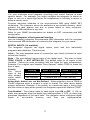
DIGITAL INPUTS (10 available)
The Integrator supports ten digital inputs, each with four individually
programmable attributes. These include:
Label - The user-assigned name of a particular input which includes the input
connection location.
State - The user-defined logical state of the digital input. The state is either
TRUE, FALSE, or NOT INSTALLED. The default state for all inputs is Not
Installed. Define the state consistent with the Label for easy interpretation.
Example: For a digital input labeled “Door Opened,” define TRUE to mean the
door is open.
Polarity
Polarity
State = TRUE
State = FALSE
The
active
Active High
Contact OPEN
Contact CLOSED
state of the
Active Low
Contact CLOSED
Contact OPEN
relay contact
Not
Defined
Contacts
are
NOT
INSTALLED
inputs which
includes
Active High, Active Low, and Not Defined. Define polarity to force a TRUE or
FALSE response when a contact is open or closed. The table above details
polarity definitions. Example: If the polarity for a particular input is Active High
and the contact is open when queried, the Integrator reports the State as TRUE.
Trap Enabled - Turns alarm traps for each digital input ON or OFF. If ON, an
alarm trap generates when the digital input changes state. If OFF, no alarm trap
generates regardless of the input state. The integrator stores configured digital
inputs
in
non-volatile
memory
until
they
are
reprogrammed.
17
OUTPUT RELAYS (2 available)
Output relays control the On/Off status of digital outputs.
attributes include:
Control relays
Label -The user-assigned name of a particular output relay. A sheet of adhesive
labels supplied in this manual affix to the front of the Integrator to identify output
relays.
State - The user-defined logical state of the output relay. Allows manual
opening or closing of a relay contact. The state is either ON or OFF. When ON,
normally open contacts are closed; when OFF, normally closed contacts are
closed.
Control - Attaches a particular relay to any digital input and/or sensor. Enter a
control value or sum of several values that opens the relay when corresponding
condition(s) are TRUE. Appendix A lists all control values and their
corresponding input or sensor.
Examples: If the control value is set to 1 for Relay1Control, the relay
automatically opens when Digital Input 1 state is TRUE. If the control value is set
to 33 (the sum of Digital Input 1 and Digital Input 5 TRUE), the relay
automatically opens when either the Digital Input 1 state is TRUE or Digital Input
5 state is TRUE.
The SNMP Agent uses “OR” logic when decoding a sum of control values. A sum
of control values opens the relay when any one of the conditions associated with
the addends of the sum are met.
AUDIBLE ALARM (Horn)
The Integrator sounds an alarm when predefined digital input or sensor
conditions are met. Alarm attributes include:
State - The user-defined logical state of the alarm. The state is either ON or
OFF. When ON, the alarm sounds; when OFF, the alarm is silent.
Control - Attaches a particular alarm to any digital input and/or sensor. Enter a
control value or sum of several values that sounds the alarm when corresponding
condition(s) are TRUE. Appendix A lists all control values and their
corresponding input or sensor.
Examples: If the control value is set to 1 for Audible Control, the alarm
automatically sounds when the Digital Input 1 state is TRUE. If the control value
is set to 33 (the sum of Digital Input 1 and Digital Input 5 TRUE), the alarm
automatically sounds when either the Digital Input 1 state is TRUE or Digital
Input 5 state is TRUE.
The SNMP Agent uses “OR” logic when decoding a sum of control values. A sum
of control values opens the relay when any one of the conditions associated with
the addends of the sum are met.
18
FRONT PANEL LED LIGHTS (3 provided)
The Integrator has three LED status indicators on the front panel. Configure
them to turn On or Off when predefined digital input or sensor conditions are met.
LED attributes include:
Label - The user-assigned name of a particular output relay. A sheet of
adhesive labels supplied in this manual affix to the front of the Integrator to
identify LED status indicators.
State - The user-defined logical state of the alarm. The state is either ON or
OFF. When ON, the indicator lights; when OFF, the indicator does not light.
Control - Attaches a particular LED status indicator to any digital input
and/or sensor. Enter a control value or sum of several values that lights the
LED when corresponding condition(s) are TRUE. Appendix A lists all control
values and their corresponding input or sensor.
Examples: If the control value is set to 1 for Audible Control, the LED
automatically lights when the Digital Input 1 state is TRUE. If the control
value is set to 17 (the sum of Digital Input 1 and Digital Input 5 TRUE), the
LED automatically lights when either the Digital Input 1 state is TRUE or
Digital Input 5 state is TRUE.
The SNMP Agent uses “OR” logic when decoding a sum of control values. A
sum of control values opens the relay when any one of the conditions
associated with the addends of the sum are met.
TEMPERATURE SENSORS (3 available)
The Integrator accommodates up to three temperature sensors.
attributes include:
Sensor
Label - The user-assigned name of a particular temperature sensor, which
includes the sensor connection location.
State - The user-defined logical state of the alarm. The state is either
INSTALLED or UNINSTALLED. The default state is UNINSTALLED until the
sensor is physically connected.
Temperature Value - The temperature the sensor reads at the connection,
user-programmable to °F or °C. The reported temperature is the actual
temperature plus the offset value (see below).
Temperature Offset - A °F or °C temperature value automatically added to
actual temperature sensor readings to compensate for known temperature
fluctuations.
Examples: If the Integrator sensor reads 27°C and an external thermometer
at the sensor connection reads 29°C, set the sensor’s temperature offset to
2°C. If the Integrator sensor reads 27°C and the external thermometer reads
25°C, set the offset to -2°C.
High Limit Alarm - Indicates the temperature at or above which a trap
generates for a high-temperature alarm. Enter high limit values in either °F
or °C.
19
Low Limit Alarm - Indicates the temperature at or below which a trap
generates for a low-temperature alarm. Enter low limit values in either °F or
°C.
Calibrate - An automatic offset similar to the temperature offset and
applicable only to Temp 3 (thermistor).
HUMIDITY SENSORS (2 available)
The Integrator accommodates two humidity sensors. Sensor attributes include:
Label - The user-assigned name of a particular humidity input, which
includes the input connection location.
State - The user-defined logical state of the alarm. The state is either
INSTALLED or UNINSTALLED. The default state is UNINSTALLED until the
sensor is physically connected.
Humidity Value - The relative humidity (20% to 80%) the sensor reads at
the connection. The reported relative humidity is the actual humidity plus the
humidity offset value (see below).
Humidity Offset - A value added to the actual humidity sensor readings to
compensate for known discrepancies.
Examples: If the Integrator sensor reads 60% RH and an external gauge at
the connection reads 62%, set the sensor’s humidity offset to 2%. If the
Integrator sensor reads 60% RH and the external gauge reads 58%, set the
offset to -2%.
High Limit Alarm - Indicates the relative humidity at or above which a trap
generates for a high-humidity alarm.
Low Limit Alarm - Indicates the relative humidity at or below which a trap
generates for a low-humidity alarm.
TRAPS
Use SNMP SET commands to program the following trap alarms ON or OFF:
Digital Inputs 1 through 10 TRUE trap
Digital Inputs 1 through 10 FALSE trap
Temperature sensors 1 through 3 HIGH trap
Temperature sensors 1 through 3 LOW trap
Temperature sensors 1 through 3 NORMAL trap
Humidity sensors 1 and 2 HIGH trap
Humidity sensors 2 and 2 LOW trap
Humidity sensors 1 and 2 NORMAL trap.
20
LCM Master Control
The LCM and SiteNet Integrator will allow for master control of all six
receptacles. This includes:
Master On / Off—Controls all six LCM receptacles with on, off or reboot. If On,
the receptacles can be individually controlled after the Master time delay. If Off,
the receptacles are all turned off. If Reboot, receptacles are turned off for 20
seconds and then turned on. The receptacles can then be individually controlled
after the Master time delay.
Master Delay—Used to delay power to each receptacle after an On or Reboot of
the Master On / Off. The power on will be staggered from receptacle 1 through
6.
LCM Individual Control
The LCM and SiteNet Integrator will allow for individual control of six receptacles
with four programmable attributes and one read only attributes. These include:
Label—The user assigned name of an individual receptacle.
State—The user defined individual control state of each receptacle. The state is
either on, off, reboot, event_on, event_off or event_reboot.
If on, power will be turned on after the receptacle delay time.
If off, power will be turned off after the receptacle delay time.
If reboot, power will be removed after the receptacle delay time for 20
seconds and then power will be restored.
If event_on, power will be off unless the condition specified by the control
attribute is satisfied. Upon the event, the receptacle will be turned on after
the receptacle delay time. When the event clears, power will be removed
from the receptacle.
If event_off, power will be on unless the condition specified by the control
attribute is satisfied. Upon the event, the receptacle will be turned off after
the receptacle delay time. When the event clears, power will be restored to
the receptacle.
If event_reboot, power will be on unless the condition specified by the
control attribute is satisfied. Upon the event, the receptacle will be turned off
after the receptacle delay time. After 20 seconds, the power will be restored
to the receptacle.
Control—Attaches a particular receptacle to any digital input and/or sensor.
Enter a control value or sum of several values that will set the output to the state
specified by the control state.
Status—A read only variable that indicates the status of the receptacle.
Receptacle Delay—Used to delay on, off, reboot or event control of the
receptacle.
21
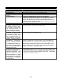
INTEGRATOR ENVIRONMENTAL MIB
MIB Variable Name
envIdent Group
envIdentManufacturer
envIdentModel
EnvIdentSoftware
Version
envIdentSpecific
envDigital Inputs Group
envDigInput1State envDigIn
put2State envDigInput3Stat
e envDigInput4State envDi
gInput5State envDigInput6S
tate envDigInput7State env
DigInput8State envDigInput
9State envDigInput10State
envDigInput1Label envDigIn
put2Label envDigInput3Lab
el envDigInput4Label envDi
gInput5Label envDigInput6L
abel envDigInput7Label en
vDigInput8Label envDigInpu
t9Label envDigInput10Label
envDigInput1Polarity envDig
Input2Polarity envDigInput3
Polarity envDigInput4Polarit
y envDigInput5Polarity env
DigInput6Polarity envDigInp
ut7Polarity envDigInput8Pol
arity envDigInput9Polarity e
nvDigInput10Polarity
envDigInput1TrapEnabled e
nvDigInput2TrapEnabled en
vDigInput3TrapEnabled env
DigInput4TrapEnabled envD
igInput5TrapEnabled envDig
Input6TrapEnabled envDigIn
put7TrapEnabled envDigInp
ut8TrapEnabled envDigInput
9TrapEnabled envDigInput1
0TrapEnabled
MIB Variable Description
The Environmental Control Unit manufacturer.
The Environmental Control Unit Model designation.
The Environmental SNMP Agent software version.
A reference to MIB definitions specific to the particular
Environmental Unit being managed. Use this object to locate the
product-specific MIB for this device. If this information is not
present, set its value to the syntactically valid Object Identifier { 0 0
}, any conformant implementation of ASN.1 and BER must be able
to generate and recognize this value.
The state of a Digital Input controlled by the Polarity variable
associated with it. See Polarity variable below.
A user-defined text string associated with a Digital Input. The text
string is stored in non-volatile memory.
Polarity controls the value returned by the State variable. Setting
Polarity to notDefined (3) causes State to return notInstalled (3);
when Polarity is set to activeHigh (1), asserting the signal on the
Digital Input causes State to return true (1); when Polarity is set to
activeLow (2), deasserting the signal on the Digital Input causes
State to return true (1). In all other cases, State returns false (2).
Polarity is stored in non-volatile memory.
Associate a Trap with the State variable for a Digital Input. Set the
TrapEnabled variable to true (1) to generate a Trap message when
the input changes state. Set the TrapEnabled variable to false (2)
to generate no Trap message regardless of the state. TrapEnabled
is stored in non-volatile memory.
22
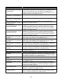
MIB Variable Name
envRelays Group
envRelay1State envRelay2S
tate
envRelay1Label envRelay2L
abel
envRelay1Control envRelay
2Control
envOutputs Group
envAudibleState
envAudibleControl
envLED1State envLED1Stat
e envLED1State
envLED1Label envLED1Lab
el envLED1Label
envLED1Control envLED2C
ontrol envLED3Control
envAlarms Group
envSummaryAlarm
MIB Variable Description
The state of an Output Relay. Set State to on (1) to activate the
Output Relay and close normally open contacts. Set State to off (2)
to deactivate the Output Relay and close normally closed contacts.
User-defined text strings associated with an Output Relay stored in
non-volatile memory.
Set Control to 0 for direct Output Relay control by the SNMP
Manager. When Control contains any of the Control Values below
or a value resulting from the sum of these values, the agent
activates the output. The agent deactivates the output when
conditions clear. Control is stored in non-volatile memory.
The state of the Audible Output. Set State to on (1) to activate the
output. Set State to off (2) to mute the output.
Set Control to 0 for direct Audible Output control by the SNMP
Manager. When Control contains any of the Control Values below
or a value resulting from the sum of these values, the agent
activates the output. The agent deactivates the output when
conditions clear. Control is stored in non-volatile memory.
The state of an Output LED. Set State to on (1) to light the LED.
Set State to off (2) to extinguish the LED.
User-defined text strings associated with an Output LED stored in
non-volatile memory.
Set Control to 0 for direct LED control by the SNMP Manager.
When Control contains any of the Control Values below or a value
resulting from the sum of these values, the agent activates the
output. The agent deactivates the output when conditions clear.
Control is stored in non-volatile memory.
This variable = 0 when no Digital Inputs are true and no other alarm
conditions exist. When alarms are active or Digital Inputs are true,
the value of envSummaryAlarm indicates which alarms and inputs
are active as a sum of the Control Values below.
ENVIRONMENTAL MIB CONTROL VALUES
DigitalInput1State true(1)
DigitalInput2State true(1)
DigitalInput3State true(1)
DigitalInput4State true(1)
DigitalInput5State true(1)
DigitalInput6State true(1)
DigitalInput7State true(1)
DigitalInput8State true(1)
DigitalInput9State true(1)
DigitalInput10State true(1)
1
2
4
8
16
32
64
128
256
512
Temperature1 above HighLimit
Temperature1 below LowLimit
Temperature2 above HighLimit
Temperature2 below LowLimit
Temperature3 above HighLimit
Temperature3 below LowLimit
Humidity1 above HighLimit
Humidity1 below LowLimit
Humidity2 above HighLimit
Humidity2 below LowLimit
23
1024
2048
4096
8192
16384
32768
65536
131072
262144
524288
MIB Variable Name
envTemperatureSensors Group
envTemperature1State envT
emperature2State envTemp
erature3State
envTemperature1F envTem
perature2F envTemperature
3F
envTemperature1C envTem
perature2C envTemperature
3C
envTemperature1Label env
Temperature2Label envTem
perature3Label
envTemperature1OffsetF en
vTemperature2OffsetF envT
emperature3OffsetF
envTemperature1OffsetC en
vTemperature2OffsetC envT
emperature3OffsetC
envTemp1HighLimitF envTe
mp2HighLimitF envTemp3Hi
ghLimitF
envTemp1HighLimitC envTe
mp2HighLimitC envTemp3H
ighLimitC
envTemp1LowLimitF envTe
mp2LowLimitF envTemp3Lo
wLimitF
envTemp1LowLimitC envTe
mp2LowLimitC envTemp3Lo
wLimitC
env Temp3Calibrate
envHumiditySensors Group
envHumidity1State envHumi
dity2State
envHumidity1RH envHumidi
ty2RH
envHumidity1Label envHumi
dity2Label
envHumidity1Offset envHum
idity2Offset
envHumidity1HighLimit env
Humidity2HighLimit
envHumidity1LowLimit envH
umidity2LowLimit
MIB Variable Description
The state of a Temperature Input. Set State to installed (2) to
indicate valid TemperatureF and TemperatureC variables from the
sensor connected to the input. Set State to notInstalled (1) to
indicate invalid TemperatureF and TemperatureC variables. This
variable is stored in non-volatile memory.
Sensor temperature in degrees Fahrenheit.
Sensor temperature in degrees Celsius.
User-defined text strings associated with a Temperature Input
stored in non-volatile memory.
A temperature correction offset associated with the Tempera-tureF
variable for a Temperature Input. OffsetF is added to the value
from the temperature sensor to obtain the value of Temp-eratureF.
Changing OffsetF affects OffsetC for this Input as well. OffsetF is
stored in non-volatile memory.
A temperature correction offset associated with the Tempera-tureC
variable for a Temperature Input. OffsetC is added to the value
from the temperature sensor to obtain the value of Temp-eratureC.
Changing OffsetC affects OffsetF for this Input as well. OffsetC is
stored in non-volatile memory.
When TemperatureF for this Input reaches or exceeds the value of
HighLimitF, a trap signifies a high-temperature condition for this
Input. HighLimitF is stored in non-volatile memory.
When TemperatureC for this Input reaches or exceeds the value of
HighLimitC, a trap signifies a high-temperature condition for this
Input. HighLimitC is stored in non-volatile memory.
When TemperatureF for this Input reaches or recedes below the
value of LowLimitF, a trap signifies a low-temperature condition for
this Input. LowLimitF is stored in non-volatile memory.
When TemperatureC for this Input reaches or recedes below the
value of LowLimitC, a trap signifies a low-temperature condition for
this Input. LowLimitC is stored in non-volatile memory.
A temperature offset correction routine associated with
Temperature Sensor 3.
The state of a Humidity Input. Set State to installed (2) to indicate
valid HumidityRH variable from the sensor connected to the input.
Set State to notInstalled (1) to indicate invalid HumidityRH variable.
This variable is stored in non-volatile memory.
The Humidy for this sensor in percent RH.
User-defined text strings associated with a Humidity Input stored in
non-volatile memory
A temperature correction offset associated with the HumidityRH
variable for a Humidity Input. The Offset is added to the value from
the humidity sensor to obtain the value of HumidityRH. Offset is
stored in non-volatile memory.
When HumidityRH for this Input reaches or exceeds the value of
HighLimit, a trap signifies a high-humidity condition for this Input.
HighLimit is stored in non-volatile memory.
When HumidityRH for this Input reaches or recedes below the
value of LowLimit, a trap signifies a low-humidity condition for this
Input. LowLimit is stored in non-volatile memory.
24
MIB Variable Name
envTraps Group
envSummaryAlarmTrap
envDigInput1TrueTrap envD
igInput2TrueTrap envDigInp
ut3TrueTrap envDigInput4Tr
ueTrap envDigInput5TrueTr
ap envDigInput6TrueTrap e
nvDigInput7TrueTrap envDi
gInput8TrueTrap envDigInp
ut9TrueTrap envDigInput10
TrueTrap
envDigInput1FalseTrap env
DigInput2FalseTrap envDigI
nput3FalseTrap envDigInput
4FalseTrap envDigInput5Fal
seTrap envDigInput6FalseTr
ap envDigInput7FalseTrap
envDigInput8FalseTrap env
DigInput9FalseTrap envDigI
nput10FalseTrap
envTemperature1HighTrap
envTemperature2HighTrap
envTemperature3HighTrap
envTemperature1LowTrap e
nvTemperature2LowTrap en
vTemperature3LowTrap
envTemperature1NormalTrap
envTemperature2NormalTr
ap envTemperature3Normal
Trap
envHumidity1HighTrap env
Humidity2HighTrap
envHumidity1LowTrap envH
umidity2LowTrap
envHumidity1NormalTrap en
vHumidity2NormalTrap
MIB Variable Description
An envSummaryAlarmTrap generates each time a digital input
State variable changes to true (1) or whenever a temperature or
humidity goes above the HighLimit or below the LowLimit.
A Digital Input TrueTrap signifies that the State variable for this
Digital Input has changed from false (2) to true (1). This trap is not
generated if the Digital Input's TrapEnabled variable is not true
(1).
A Digital Input FalseTrap signifies that the State variable for this
Digital Input has changed from true (1) to false (2). This trap is not
generated if the Digital Input's TrapEnabled variable is not true (1).
A Temperature Input HighTrap signifies that the sensor reading
exceeds the HighLimit value.
A Temperature Input LowTrap signifies that the sensor reading is
less than the LowLimit value.
A Temperature Input NormalTrap signifies that the sensor reading
is within the range bounded by HighLimit and LowLimit values.
A Humidity Input HighTrap signifies that the sensor reading
exceeds the HighLimit value.
A Humidity Input LowTrap signifies that the sensor reading is less
than the LowLimit value.
A Humidity Input NormalTrap signifies that the sensor reading is
within the range bounded by HighLimit and LowLimit values.
25
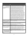
INTERGRATOR LCM MIB
MIB Variable Name
envReceptacles Group
envReceptacles
Group envReceptacle1State
envReceptacle2
State envReceptacle3State
envReceptacle4State env
Receptacle5State envRecep
tacle6State
envReceptacle1Label envR
eceptacle2Label envRecept
acle3Label envReceptacle4
Label envReceptacle5Label
envReceptacle6Label
envReceptacle1Control env
Receptacle2Control envRec
eptacle3Control envRecepta
cle4Control envReceptacle5
Control envReceptacle6Con
trol
envReceptacle1Status envR
eceptacle2Status envRecept
acle3Status envReceptacle4
Status envReceptacle5Statu
s envReceptacle6Status
envReceptacle1ReceptDelay
envReceptacle2ReceptDela
y envReceptacle3ReceptDel
ay envReceptacle4ReceptD
elay envReceptacle5Recept
Delay envReceptacle6Rece
ptDelay
MIB Variable Description
The state of a LCM Receptacle. Set state to on (1) to apply power
to the receptacle after the delay specified by the corresponding
envReceptacleReceptDelay. Set state to off (2) to remove power
from the receptacle after the delay specified by the corresponding
envReceptacleReceptDelay. Set state to reboot (3) to remove
power from the receptacle after the delay specified by the
corresponding envReceptacleReceptDelay for 20 seconds and
then turn power back on. Set state to event_on (4) to have power
at the receptacle off unless the condition specified by the
corresponding envRecetpacleControl is satisfied. Upon the event,
the receptacle will be turned on after the delay specified by the
corresponding envReceptacleReceptDelay. When the event
clears, power will be removed from the receptacle. If the event
clears before the time delay expires, the receptacle will not be
turned on and the time delay will reset. . Set state to event_off (5)
to have power at the receptacle on unless the condition specified
by the corresponding envRecetpacleControl is satisfied. Upon the
event, the receptacle will be turned off after the delay specified by
the corresponding envReceptacleReceptDelay. When the event
clears, power will be restored to the receptacle. If the event clears
before the time delay expires, the receptacle will not be turned off
and the time delay will reset. Set state to event_reboot (6) to have
power at the receptacle on unless the condition specified by the
corresponding envRecetpacleControl is satisfied. Upon the event,
the receptacle will be turned off after the delay specified by the
corresponding envReceptacleReceptDelay. After 20 seconds, the
power will be restored to the receptacle. This process is nonreversible, if the event clears before the time delay expires, the
receptacle delay process will continue. State is stored in nonvolatile memory , except for reboot since it is a temporary condition.
A user-defined text string associated with a receptacle. The
maximum length of the text string is 64 characters. The text string
is stored in non-volatile memory.
When Control contains any of the Control Values, or a value
resulting from the sum of any of these values the Agent will set the
output to the state specified by the corresponding
envReceptacleControlState. When all conditions clear the
receptacle will return to the initial state. The control variable is
stored in non-volatile memory.
The status of the receptacle. When status is on (1) power will be
available on the receptacle. When status is off (2) power will not
be available on the receptacle. When status is reboot (3) the
power is being removed from the receptacle for 20 seconds and
then power will be restored. When status is event_on (4) power will
be available on the receptacle. When status is event_off (5) no
power will be available from the receptacle. When status is
event_reboot (6) the power is being removed from the receptacle
for 20 seconds and then power will be restored.
Receptacle control delay is used to delay the on, off, reboot or
event control of the receptacle. Delay is stored in non-volatile
memory.
26
MIB Variable Name
envReceptacleMaster
envReceptacleMasterOnOff
envReceptacleMasterDelay
MIB Variable Description
The state of the Receptacle Master Control. When the state is on
(1) power to each receptacle will be under the control of the
individual states and events. When state is set to off (2) no power
is available from any receptacle. When set to reboot (3), power will
be removed from all receptacles for 20 seconds and then returned
to control of the individual states and events.
Receptacle master delay is used to delay the power to each
receptacle after a on or reboot of the envReceptacleMasterOnOff.
The power return will be staggered from 1 thru 6.
SAMPLE TFTP FILE
#
#
#
#
Example Liebert UPS SNMP Agent Configuration file for BOOTP
and TFTP. The user names this file and stores it on the bootp server. The server sends the name of the file to the agent when the
agent requests it.
sysDescr
sysLocation
sysContact
sysName
#
Liebert SNMP agent
Columbus, OH
Your Name + 1 614 555 1234
Sys Name Here
Set snmpEnableAuthenTraps to 1 (Enabled) or 2 (Disabled)
snmpEnableAuthenTraps 1
#
#
#
#
#
#
#
#
#
#
#
#
Community Specification.
The format of the value clause is:
<community name, IP address, privileges>
• The community name may be any string.
• The IP address indicates the remote site for which this community
is valid. If the IP address is 0.0.0.0, any address may communicate using that community name.
• The privileges are any one of the following:
READ for read only.
WRITE for read/write.
NONE to lock out a community name.
community
community
#
#
#
public
woff
0.0.0.0
192.147.142.16
Trap Community Specification.
The format of the value clause is:
<community name, IP address>
trap
trap
test2
fileserver
192.147.142.15
192.147.142.16
27
read
write
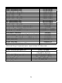
INTEGRATOR & LCM COMPONENTS AND PARTS
Desk Top/Ethernet 50Hz
Desk Top/Ethernet 60Hz
Desk Top/Token Ring 50Hz
Desk Top/Token Ring 60Hz
19” Rack/Ethernet 50Hz
19” Rack/Ethernet 60Hz
19” Rack/Token Ring 50Hz
19” Rack/Token Ring 60Hz
24” Rack/Ethernet 50Hz
24” Rack/Ethernet 60Hz
24” Rack/Token Ring 50Hz
24” Rack/Token Ring 60Hz
Integrator Power Supply - 120 VAC, 60 Hz
Integrator Power Supply - 220 VAC, 50 Hz
Integrator to Terminal Cable/Adapter
Ferrite Beads - .5”/.25”
Wall-Mount Thermistor
Liquitect (water detection) with Dry Contact Output*
120/24 VAC Plug-In Transformer*
Temperature / Humidity Sensor – 10ft (3m) cable
Temperature / Humidity Sensor – 30ft (9m) cable
LCM / 120 VAC
LCM / 230 VAC
10-Foot 8-Pin DIN Cable to LCM
INTGR-DSE50
INTGR-DSE60
INTGR-DST50
INTGR-DST60
INTGR-19SE50
INTGR-19SE60
INTGR-19ST50
INTGR-19ST60
INTGR-24SE50
INTGR-24SE60
INTGR-24ST50
INTGR-24ST60
141004P1
141669P1
146618P1 / 146617P1
146735P1 / 146736P1
135208P1
141603G1L
141469P1
141604G1L
141605G1L
LCM-NEMA-15
LCM-IEC-10
146654G1
*Liquitect requires 12 or 24 VAC power which must be provided by the customer or via the
120/240 VAC Plug-In Transformer Option. Option includes 65 ft (20m) cable.
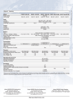
Integrator Specifications
Power Requirements Main/Aux
Dimensions H x W x D
9 VDC, 15 Watts
1.5 x 17.25 x 7.5 in
(3.8 x43.8 x 19.0 cm)
4.74 lbs (2.15 kg)
32º to 140º F (0º to 60º C)
32º to 95º F (0º to 35º C)
20% to 80% RH
UL, cUL, FCC, CE marked
Unit weight / Shipping weight
Temperature Range
Thermistor Range
Humidity Range
Agency Approvals
28
LCM 120V SPECIFICATIONS
Power Requirements
Power Input
Power Output
Dimensions HxWxD
Unit Weight / Shipping
Weight
Circuit Breaker
LED Indicators
Agency Approvals
120 VAC Nominal, 50 or 60 Hz (Range 80-132 VAC)
EN 60320/C14 Connector (120 VAC, 15 Amps)
(6) 5-15R Receptacles (Max. Total Current = 12 Amps)
1.75 x 17.25 x 7.6 inches / 4.4 x 43.8 x 19.3 cm
5.5 lbs. (2.5 kg) / 10.7 lbs. (4.9 kg)
15 amp
Each Output Plus Main Power
UL, cUL
LCM 230V SPECIFICATIONS
Power Requirements
Power Input
Power Output
Dimensions HxWxD
Unit Weight / Shipping
Weight
Circuit Breaker
LED Indicators
Agency Approvals
230 VAC Nominal, 50 or 60 Hz (Range 160-240 VAC)
EN 60320/C14 Connector (230 VAC, 10 Amps)
(6) EN 60320/C13 Receptacles
(Max. Total Current = 10 Amps)
1.75 x 17.25 x 7.6 inches / 4.4 x 43.8 x 19.3 cm
5.5 lbs. (2.5 kg) / 10.7 lbs. (4.9 kg)
10 amp
Each Output Plus Main Power
CE Marked, EN60950
29
120V Limited Warranty
This Liebert product is warranted to be free of defects in material and workmanship for a period of one year
from the date of product purchase from Liebert. The product purchase date will be determined from the
Liebert Sales Order Acknowledgment or such other sales documentation as Liebert, in its sole discretion,
deems acceptable. If any part or portion of the Liebert product fails to conform to the Warranty within the
Warranty period, Liebert will furnish factory remanufactured products for replacement of that portion or part.
This Warranty is extended to the first person, firm, association or corporation for whom the Liebert product
specified herein is originally installed for use in the United States (the "User"). This Warranty is not
transferable or assignable without the prior written permission of Liebert.
Liebert assigns to User any warranties which are made by manufacturers and suppliers of components of the
Liebert product and which are assignable, but Liebert make NO REPRESENTATIONS as to the effectiveness
or extent of such warranties, assumes NO RESPONSIBILITY for any matters which may be warranted by such
manufacturers or suppliers and extends no coverage under this Warranty to such components.
Liebert warrants for the period and on the terms of the Warranty set forth herein that the Liebert product will
conform to the descriptions contained in Liebert's final invoices, orders and Liebert product brochures. Liebert
does not control the installation and use of any Liebert product. Accordingly, it is understood that the
Descriptions are NOT WARRANTIES OF PERFORMANCE and NOT WARRANTIES OF FITNESS FOR A
PARTICULAR PURPOSE.
Within a reasonable time, but in no case to exceed thirty days, after User's discovery of a defect, User shall
contact Liebert and request a return authorization number. User shall ship the product, with proof of purchase,
to Liebert freight prepaid. Liebert products shipped to Liebert without a return authorization number will be
refused and returned freight collect to User at User's expense. Products shipped by User to Liebert which
have incurred freight damage due to User's improper packaging of the product will not be covered by this
Warranty and any replacement parts, components, or products needed will be invoiced in the full current price
amount and returned freight collect to User.
Subject to the limitations specified herein, Liebert will replace, without charge for Liebert labor or materials,
subsequent to its inspection and F.O.B. User's facility, the product shipped to Liebert with a return
authorization number and warranted hereunder which does not conform to this Warranty. Warranty coverage
will be extended only after Liebert's inspection discloses the claimed defect and shows no signs of treatment
of use which would void the coverage of this Warranty.
THIS WARRANTY DOES NOT COVER DAMAGE OR DEFECT CAUSED BY misuse, improper application,
wrong or inadequate electrical current or connection, negligence, inappropriate on-site operating conditions,
corrosive atmosphere, repair by non-Liebert designated personnel, accident in transit, tampering, alterations,
exposure to the elements, Acts of God, theft, installation contrary to Liebert's recommendations, or in any
event if the Liebert serial number has been altered, defaced, or removed.
THIS WARRANTY DOES NOT COVER installation costs, circuit breaker resetting, or maintenance or service
items and further, except as provided herein, does NOT include labor costs or transportation charges arising
from the replacement of the Liebert product or any part thereof or charges to remove the same from any
premises of User.
REPLACEMENT OF A DEFECTIVE PRODUCT OR PART THEREOF DOES NOT EXTEND THE
ORIGINAL WARRANTY PERIOD.
THIS WARRANTY IS IN LIEU OF AND EXCLUDES ALL OTHER WARRANTIES, EXPRESS OR
IMPLIED, INCLUDING MERCHANTABILITY AND FITNESS FOR A PARTICULAR PURPOSE.
USER'S SOLE AND EXCLUSIVE REMEDY IS REPLACEMENT OF THE LIEBERT PRODUCT AS SET
FORTH HEREIN.
IF USER'S REMEDY IS DEEMED TO FAIL OF ITS ESSENTIAL PURPOSE BY A COURT OF
COMPETENT JURISDICTION, LIEBERT'S RESPONSIBILITY FOR PROPERTY LOSS OR DAMAGE
SHALL NOT EXCEED ONE TIMES THE NET PRODUCT PURCHASE PRICE.
IN NO EVENT SHALL LIEBERT ASSUME ANY LIABILITY FOR INDIRECT, SPECIAL, INCIDENTAL,
OR ECONOMIC CONSEQUENTIAL DAMAGES OF ANY KIND WHATSOEVER, INCLUDING
WITHOUT LIMITATION LOST PROFITS, BUSINESS INTERRUPTION, OR LOSS OF DATA,
WHETHER ANY CLAIM IS BASED UPON THEORIES OR CONTRACT, NEGLIGENCE, STRICT
LIABILITY, TORT, OR OTHERWISE.
NO SALESPERSON, EMPLOYEE OR AGENT OF LIEBERT IS AUTHORIZED TO ADD TO OR VARY
THE TERMS OF THIS WARRANTY. Warranty terms may be modified, if at all, only by a writing signed
by a Liebert officer.
This Warranty is effective as of the date of receipt of payment and supersedes all previous warranties.
Liebert reserves the right to supplement or change the terms of this Warranty in any subsequent
warranty offering to User of others.
In the event that any provision of this Warranty should be or becomes invalid and/or unenforceable
during the warranty period, the remaining terms and provisions shall continue in full force and effect.
This Warranty is given in and intended to be construed under the laws of the State of Ohio.
This Warranty represents the entire agreement between Liebert and User with respect to the subject
matter herein and supersedes all prior or contemporaneous oral or written communications,
representations, understandings or agreements relating to this subject.
30
230V LIMITED WARRANTY
Liebert Corporation extends the following LIMITED WARRANTY to the
purchaser and to its customer (collectively referred to as the "Purchaser"): the
enclosed Product and components are free from defects in materials and
workmanship under normal use, service, and maintenance FOR A PERIOD OF
TWO YEARS FROM THE DATE OF ORIGINAL PURCHASE from Liebert or the
Liebert dealer or retailer. THE FOREGOING WARRANTY IS THE ONLY
WARRANTY GIVEN AND NO OTHER WARANTY IS PROVIDED, EXPRESS
OR IMPLIED, INCLUDING WITHOUT LIMITATION, MERCHANTABILITY OR
FITNESS FOR A PARTICULAR PURPOSE. Certain aspects of disclaimers are
not applicable to consumer products acquired by individuals and used for
personal, family, or household purposes (as distinguished from industrial or
other purposes). Local laws may not allow limitations on how long an implied
warranty lasts, so the above limitation may not apply to you. This warranty gives
you specific legal rights, and you may have other rights which vary according to
local law.
Certain repairs or services are the responsibility of the Purchaser and the
Purchaser is expected to pay for them. This warranty does not extend either to
products with removed or altered serial numbers or to any losses or damages
due to act of God or source external to the product, misuse, accident, abuse,
neglect, negligence, unauthorized modification, alteration, or repair, use beyond
rated capacity, or improper installation, maintenance, application or use,
including, without limitation, use in a manner contrary to the accompanying
instructions or applicable codes.
If the product fails to conform with the above warranty within the two year
warranty period, Liebert will repair or replace the product, at Liebert's option.
Repairs or replacements are warranted for the remainder of the original
warranty period. To make a warranty claim, purchaser should call a Liebert
Representative to obtain a Returned Goods Authorization number and shipping
instructions. Return transportation costs to Liebert are the responsibility of the
Purchaser.
“LIFE SUPPORT” APPLICATIONS
Due to the diversity of applications and consideration to be applied in each
case, Liebert does not recommend or knowingly sell its products for such use.
The responsibility for risk assessment and management in applications where
the malfunction or failure of the product could be reasonably expected to give
rise to a risk of human life shall be the sole responsibility of the purchaser.
Liebert accepts no liability for consequential harm in such applications.
31
SiteNet® Integrator
SNMP Communications
for Integrated Products
Load Control Module
SNMP Remote Control
of Critical Loads
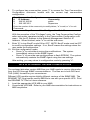
Technical Support
U.S.A.
Outside the U.S.A.
U.K.
France
Germany
Italy
Netherlands
E-mail
Web site
Worldwide FAX tech support
1-800-222-5877
614-841-6755
+44 (0) 1793 553355
+33 (0) 1 43 60 01 77
+49 89 99 19 220
+39 2 98250 1
+31 (0) 475 503333
[email protected]
http://www.liebert.com
+614-841-5471
The Company Behind The Products
With more than 500,000 installations around
the globe, Liebert is the world leader in
computer protection systems.
Since its
founding in 1965, Liebert has developed a
complete range of support and protection
systems for sensitive electronics:
•
•
•
•
•
Environmental systems: close-control air
conditioning from 1.5 to 60 tons.
Power conditioning and UPS with power
ranges from 250 VA to more than 1000 kVA.
Integrated
systems
that provide both
environmental and power protection in a
single, flexible package.
Monitoring and control — on-site or remote —
from systems of any size or location
Service and support, through more than 100
service centers around the world, and a 24hour Customer Response Center.
32
While every precaution has been taken
to ensure accuracy and completeness of
this literature, Liebert Corporation
assumes
no
responsibility,
and
disclaims all liability for damages
resulting from use of this information or
for any errors or omissions.
©1999 Liebert Corporation All rights
reserved
throughout
the
world.
Specifications subject to change without
notice.
® Liebert and the Liebert logo are
registered
trademarks
of
Liebert
Corporation. All names referred to are
trademarks or registered trademarks of
their respective owners.
SLI-53040 (6/99) Rev. 0