1
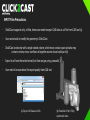
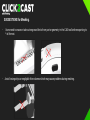
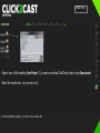
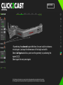
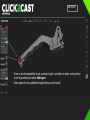
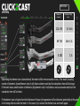
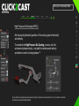
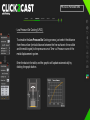
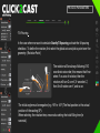
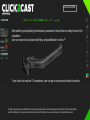
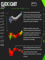
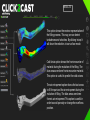
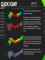
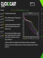
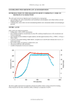
The EASYmulation
Getting Started
The EASYmulation
Some tips to consider before starting
The EASYmulation
INPUT Files Precautions.
-
Click2Cast supports only .stl files, hence user need to export CAD data as .stl file from CAD tool (a).
-
User cannot add or modify the geometry in Click2Cast.
-
Click2Cast works only with a single closed volume, which must contain a part and also may
contain runners, risers, overflows all together as one closed solid part (b)
-
Export to stl from the native format (not from an iges, step, parasolid..)
-
User need to be sure about the export quality from CAD tool.
(a) Export CAD data as stl file.
(b) Ensemble of Part, Filling
system and risers.
The EASYmulation
SUGGESTIONS for Meshing.
-
-
Users need to erase or take out engraved fonts from part or geometry in the CAD tool before exporting to
*.stl format.
Avoid having strips or negligible thin volumes which may cause problems during meshing.
The EASYmulation
SUGGESTIONS for Calculation.
If calculation stops before finishing the job, please check for following errors:
-
The dimensional units are not consitent .
-
Inadequate mesh size. Users need to have at least 3 elements over
smallest thickness. If the issue still exists, it is necesary to mesh again
with a smaller element size.
-
Check that the input metal flow temperature is not set below solidification
temperature.
The EASYmulation
Normal workflow for setting up your simulation
The EASYmulation
OPEN FILE
- Open a new .stl file selecting New Project. (1) or open an existing Click2Cast project using Open project.
- Select the model units. ( m, cm, mm, inch )
(1) Inside C:/Click2Cast/examples/ you will find some examples files.
The EASYmulation
MESHING
It is necessary to select the material inlet using automatic or advanced option before
meshing.
When using the automatic option, you have to select a pre designed ingate, either at the
runner or on the part. Just select the automatic option to add an ingate and click over the
surface that has been previously pre designed as an inlet.
If there is more than one ingate, select Add ingate. To remove the ingate use the Delete
ingate option.
It works also in
curved shape
surfaces.
In case of radius at
the selected ingate
surface, the mesher
can create an
irregular ingate
definition depending
on the assigned
element size.
The EASYmulation
MESHING
- By selecting the advanced ingate definition, the user is able to choose a
virtual ingate. Just input the dimensions of the height and width.
Select Add Ingate and click a point over the geometry to positioning the
ingate.(2) (3)
Select again for every new ingate.
(2) Positioning the ingate in a curved surface the ingate will be projected over the surface.
(3) The ingate can not overstep the limits of geometry and can not overlap to a sharp edge.
The EASYmulation
-
MESHING
There is also the possibility to use a circular ingate. Just select a radius and a position
over the geometry and select Add Ingate.
Select again for every additional ingate that you want to add.
The EASYmulation
MESHING
Number of
elements
Calculation filling time
214.576
1h16m
69.743
16m12s
4.282
12s
Depending the element size value selected, the mesh will be more accurate or less. If the mesh has a big
number of elements (small element size) it will obtain a better result but the calculation time will be longer.
If the mesh has a small number of elements (big element size) it will obtain a not so accurate result but the
calculation time will be faster.
If the element size is higher than the thickness of the part, the geometry will be distorted, potentially to the point
of not being able to create the mesh. In this case, try to reduce the element size and mesh again.
The EASYmulation
PROCESS PARAMETERS
Once the meshing is completed, the process parameters must be set up. It will take only a
few seconds. Select the part material, alloy and temperature for the part and mold.
There are two ways to set up the process parameters:
· Basic: Use this option to create a fast and general simulation.
Just select the velocity at the ingate or the
filling time.
· Advanced: Use advanced option to simulate an specific
process (HPDC, LPDC, GDC) by entering all
parameters. (next page)
The EASYmulation
PROCESS PARAMETERS
· High Pressure Die Casting (HPDC).
Set the gravity direction (position of the casting part to the mold)
and velocity.
To simulate the High Pressure Die Casting process, set first
and second phase velocity. Just add first and second velocity
and select a node to change phase. (4)
(4) Use first and second phase piston velocity if the piston and runner have been drawn. If not, it is possible to calculate
the velocities using the attached formulas.
The EASYmulation
PROCESS PARAMETERS
· Low Pressure Die Casting (LPDC).
To simulate the Low Pressure Die Casting process, just select the distance
from free surface (vertical distance between the free surface in the crucible
and the mold ingate) to the pressure curve: Time vs. Pressure curve of the
metal displacement system.
Enter the data in the table, and the graphic will update automatically by
clicking the graph button.
The EASYmulation
PROCESS PARAMETERS
· Gravity Die Casting (GDC).
There are three options to define the material flow through the ingate in gravity die
casting process.
·Filling time: Use this option if you have measured exactly the filling time
of required for your process. Units must be in seconds.
·Spoon Height: Use this option when we have totally manual ladle
operators. Choose the ladle pouring height (mm) with
respect to the mold.
·Flow rate: Use this option when you have an auto pour ladle.
The metal poured volume must be known and the units must
be in kilograms per second.
The EASYmulation
PROCESS PARAMETERS
-Tilt Pouring.
In the case where we want to simulate Gravity Tilt pouring, activate the tilt pouring
checkbox. To define the rotation, first select the global axis and pick a point over the
geometry. (Rotation Point)
The rotation will be always following XYZ
coordinate axis order; this means that if we
select Y as axis of rotation, then the
rotation will turn Z over X; if we select Z,
then X will rotate over Y, and so on.
The initial angle must be negative.(e.g. -90º or -45º) The final position is the actual
position of the casting (0º).
When selecting the rotation time, we are also setting the total filling time (in
seconds).
The EASYmulation
CALCULATION
After meshing and adjusting the simulation parameters, the software is ready to launch the
calculation.
User can request to calculate only filling, only solidification or both.(5)
Once solver has reached 1% completion, user can go to next step and check the results.
(5) When calculating only the solidification, the starting temperature will be constant throughout the entire part. When calculating filling
and the solidification, the temperature distribution at the end of the filling will be used as starting point for solidification analysis.
The EASYmulation
RESULTS
Front flow results show the filling material
evolution. This visualization gives a preliminary
idea of the filling time, and the way the part is
filled. It´s useful to decide the position of ingate
and overflows to avoid air entrapment.
Temperature evolution results show the
evolution of temperatures during filling. With
this animation, it´s possible to determine, for
example, the temperatures at which two
advancing fronts of material encounter, and
study the risk of cold welding.
With this options the user can make a cut to
see the material behavior inside. Using the label
option, the user can know the exact
temperature, velocity, material… at every node
of the part.
The EASYmulation
RESULTS
This option shows the vectors representation of
the filling process. This way, we can detect
turbulences and velocities. By clicking twice, It
will show the velocities in iso-surface mode.
Cold shuts option shows the front encounter of
material during the evolution of the filling. The
blue areas are where fronts encounter material.
This option is useful to predict the cold unions.
The air entrapment option shows the last areas
to fill the part and the air entrapment during the
evolution of filling. The blue areas are where
there is air entrapment. This option is useful in
order to avoid porosity or change the overflows
position.
The EASYmulation
RESULTS
Mold erosion shows the areas with velocities
exceeding 35 m/s, where there is high
probability of mold degradation problems
during the evolution of filling. By clicking twice,
It´s possible to change the maximum value.
The filling time option visualizes the filling time
of the different areas of the part, shown in a
color scale. This option is useful to show the
best way to fill of the part.
The solid fraction option predicts if any areas
could solidify during the filling. This is very
useful to prevent possible problems resulting
from lack of material due to solidification.
These buttons toggle between the visualization of the filling results and the
visualization of the solidification results.
The results are available once 1% of the calculation is complete. Clicking the update
button refreshes the calculation.
The EASYmulation
RESULTS
This option shows the temperature evolution
during the solidification.
The solid fraction result shows the evolution of
the solidification. The material that solidifies
will disappear from the animation and liquid
material will be represented in red. This option
predict shrinkage porosity. Change the
percentage of solidus from 0 to 1 by clicking
twice.
This option shows the elapsed time required to
fill different areas of the part, represented by
different colors. This option is useful to learn
which areas fill first and predict possibilities of
cold welding.
This option shows an instant picture of the
shrinkage porosity percentage in volume over
the total volume of the part.
The EASYmulation
RESULTS
Solidification Modulus (Volume-to-area ratio) is
the division between the casting Volume and
the surface area (Units in meters). This option
is useful in the riser designer wizard.
This option calculates the optimal riser.
Introducing the casting modulus (meters), wich
can calculate the required riser for our part,
considering if a sleeve is available or not
(exothermal or isothermal).
We can obtain a diameter and height from the
casting modulus or we can obtain a diameter
from a given height and casting modulus or
vice versa.
The EASYmulation
RESULTS
This option generates graphs.
This option
anor
optimal riser.
Click on different points
of thecalculate
geometry
in a cut and press scape.
Introducing the casting modulus (meters) we can
calculate the
required riser for our part,
A graphic will be generated
automatically
considering
we have
to show the evolution
of theseifpoints
in or not an sleeve
relation to time. (exothermal or isothermal.
We available
can obtainfor
a diameter
There are two results
graphic and height from the
casting
modulus
or we can obtain a diameter
option: temperature
and velocity
evolution
from a givenevolution
height and casting modulus or
during filling and temperature
backwards.
during solidification.
Clicking on the lines of the graphic will show the points selected over the geometry.
Add points, remove points, change the colors of the lines randomly and export the data in
grf format.
The EASYmulation
For detailed information, please contact
[email protected]
www.click2cast.com