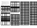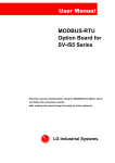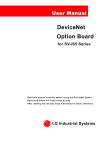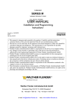
1
USER MANUAL
2.1.3. Display LED
Before Installing
Fnet OPTION BOARD
SV-iS5 Series
RX
TX
ERR
5. Operating
OP
5.1. Power On Test
This manual describes about the installation, operation, and precautions of Fnet board
Turn on the inverter power after installing the option boar, and then inverter perform
of iS5 series. Read the manual and precautions thoroughly before installation and
Power On test.
Figure 3. Display LED
operation. If not, it may cause break down of board and shorten the product life.
LED
!
z
CAUTION
RXD
Do not install the option board when the power is introduced. If not, both of the
TXD
ON during transmitting
COM▶
▶
inverter and option board may be broke down. (Attach and detach the option
ERR
ON when there is frame error
01
board to the inverter control board after the capacitor discharged)
z
ESD can cause break down of CMOS components. Do not touch the CMOS
OP
components without the board is grounded.
z
Do not change the communication cable with the inverter power is turned on.
z
Make sure to precisely insert the connector of inverter and option board
z
Make sure the connection of signal wire (P, N). P signal wire must be connected
to the P terminal.
z
First Op LED starts flickering and Err LED, Tx LED, Rx LEDs flickers at interval of 250ms.
Description
ON during receiving
Normal operation
Flickering by every 1 sec
Fnet Comm. trouble
Flickering by every 500 msec
DPRAM trouble
Flickering by every 2 sec
5.2. Setting Inverter Parameter
Set inverter parameters described below using keypad.
2.2. Installing on Inverter Board
z
Unscrew the crews that fasten the inverter board and install the copper
supporters proveded.
z
Connect terminal resistor at the last connected option board of 110 ohm, 1/2
5.2.1. Checking Option board [COM group/code# 01: PLC-GF]
This parameter checks the option board installed on inverter board. This code must
Install the Fnet board by inserting the connector of inverter and Fnet board and
tighten the screws that unscrewed from the inverter board.
display “PLC-GF”.
5.2.2. Setting Inverter Number [COM group/code# 17:
watt. (refer to Figure 6)
z
Opt B/D
PLC-GF
0 ~ 63]
This parameter sets the station number of inverter. Inverter number must match
Check the parameter unit when setting the parameters.
the station number set in PLC. Setting a same number at more than one inverter
cause communication error.
1. Introduction
Fnet board provides control and monitoring of iS5 series inverter for GLOFA PLC via
COM▶
▶ Station ID
high-speed serial communication. The communication protocol is programmed with
17
1
GLOFA PLC.
5.2.3. Setting Option Mode [COM group/code# 02]
1.1. Benefits of using Fnet board
Set the mode of Fnet board.
zIt is possible to control the inverter with high-speed communication of 1M BPS.
zEasy installation and change of a system because the control and monitoring of
inverter is accomplished by PLC programming.
COM▶
▶
zMultiple inverters can be connected only with 2 line wires, providing time saving
02
Opt mode
None
and easy maintenance.
z Easy system integration by using PLC related devices.
z None
Inverter is controlled by keypad or control terminal instead Fnet board.
1.2. Contents included
z Command
Fnet option consists 1 Fnet board, 2 connectors, 3 supporters, and manual.
Inverter takes just run commands of Forward Run, Reverse Run, and Stop
from the Fnet board.
2. Configuration and Installation
2.1.
Figure 4. Installing Fnet board on Inverter board
3. System Configuration
z Freq
Configuration
Inverter takes just frequency command from the Fnet board.
RX TX ERR OP
FUEA Module
z Cmd + Freq
Inverter takes all commands from the Fnet board.
5.2.4. Setting Lost Command [I/O group/code# 48]
Inverter #1
Inverter #2
⋅⋅⋅⋅⋅⋅⋅
Inverter #N
This parameter set the actions of inverter ahead when the communication is
disconnected (timeout) by some reasons such like DPRAM error, cable cutting.
SPNSPN
Figure 5. Example of System Configuration
3.1.
Comm. Wire Terminal Block
Frame Ground
I/O▶
▶ Lost command
Connection between PLC (FUEA) and Inverter (iS5)
48
Figure 1. Board Configuration
INV-1
FUEA(PLC)
None
INV-2
<In case of “timeout” error >
2.1.1. Comm. Wire Terminal Blcok
z None: Inverter keeps the command that just have before the disconnection
of communication.
S
P
N
S
P
Shield
P
N
N
Figure 2. Comm. Wire Terminal Blcok
S
Shield
P
Comm. Signal Wiring (P)
* Connect terminal resistor at the last connected inverter between terminal P and N.
(refer to Figure 6.)
2.1.2. Frame Ground
z Stop: Inverter stops with the deceleration ramp set at FU1 # 06.
Terminal R
110Ω, 1/2W
N
Comm. Signal Wiring (N)
* Two sets of “S”, “P”, “N” signal is connected in parallel respectively.
z FreeRun: Inverter stops with FreeRun (Coast to stop).
Shield
P
N
Figure 6. Wiring
4. Comm. Specification
This Parameter sets the time that inverter decides disconnection of communication.
Inverter takes actions of Lost Command after this set time.
Speed
1 M bps
Method
Manchester Biphase-L, Frame Synchronous method
Comm. Cable
Twisted Pair Shielded Cable, Dedicated cable
Cable Type: LIREV-AMESB 1φ
φ (PC 717 6705),
Manufacturer: LG Cable
Node
Max. 64 per line
Length
Max. 750 m
Frame Format
Field Bus(IEC TC65 / SC65C / WG6 65C 90.8)
Frame Ground is connected to the ground of inverter.
5.2.5. Setting timeOut [I/O group/code# 49]
I/O▶
▶
49
Default value is 1 second.
Time out
1.0
sec
5.2.6. Precautions
Parameter
z If the Lost Command(I/O #48) is set at “None”, inverter keeps running
Description
Unit
Read/Wri
address
Data value
5206
te
depends on the status of comm. Disconnection. This situation may cause serious
Bit 0: OC, Bit 1: OV, Bit 2: EXT-A
accident in some cases. It is strongly recommended to set at “FreeRun” or
Bit 3: BX, Bit 4: LV,
“Stop” to prevent unexpected accident.
Bit 5: Fuse Open, Bit 6: GF
z Do not set the “timeout” less than the communication cycle between PLCand
000F
Trip information
-
R
5207
5208
Bit 7: OH, Bit 8: ETH, Bit 9: OLT
inverter.
Bit 10: HW-Diag Bit 11:EXT-B
z Do not use an inverter station ID number same as other device’s station ID.
5209
Bit 12:ASHT Bit 13:OPT
This may cause a conflict in the communication system.
Bit 14:PO Bit 15:IOLT
520A
Bit 0: FX, Bit 1: RX, Bit 2: BX
6. Trouble shooting
If the communication function doesn’t work properly, check the status LED on Fnet
Input terminal
0010
voard as described below.
LED status
Cause
Blinking at 500ms
cycle
DPRAM error
ON
Damage due to noise
TXD, RXD LED : OFF
OP LED : blinking at
500ms cycle
RXD, TXD LED : OFF
OP LED : blinking at
500ms cycle
RXD, TXD LED : ON
OP LED : blinking at
1 sec.
Motor : doesn’t run
1. Check connection and
power
2,3. Repair or change.
Check connection (com.
line)
Check enable status of PLC
Check connection with
inverter
Repair or change
Check communication line
Check noise source
Fnet communication
error
Blinking at 2sec.
cycle
TXD, RXD
LED
Bit 8: P1, Bit 9: P2, Bit 10: P3
Output terminal
0011
information
Check inverter station ID is
correct
Wrong parameter set
Check set of #51 Opt mode
of EXP group
Normality
R
V1
-
R
0013
V2
-
-
0014
I
-
R
0015
RPM
-
R
0016
command(Optio
0.01Hz
0 – FFFF
5215
n)( Note 1)
0017
Command freq.
0.01Hz
R/W
0.01Hz
Ramp
5216
7. Parameter code (address is hexadecimal)
Description
Unit
address
5217
0 – 60000
0000
Inverter type
-
R
521A
521B
(Note 2) Parameter changed in common area can not be stored. The modified parameter
Data value
Write
is available during the present operation but it is not valid after the power of
521C
R
Address
9: 22 (220V class)
10: 0.75
11:1.5
12:2.2
13: 3.7
14: 5.5
15: 7.5
18: 18.5
19: 22(400V class)
16: 11
No.
521D
Description
Default
Max. value
Min. value
Unit
Cmd. Freq.
0
max freq.
Start freq.
0.01Hz
Acc. Time
50
60000
0
0.01sec
DRV#
17: 15
0100: Ver. 1.00,
5102
5103
R/W
Command freq.
0.01 Hz
R/W
N/A
Run command
-
R/W
N/A
DRV#
Dec. Time
100
60000
0
0.01sec
5221
DRV#
Drive mode
1
2
0
5222
03
1: Available
0006
5220
02
0101: Ver 1.01
0: Not available(default) – N/A
0005
DRV#
5104
DRV#
Freq. mode
0
4
0
5223
04
5105
0009
Output current
0.1 A
R
000A
Output freq.
0.01 Hz
R
000B
Output voltage
1V
R
000C
DC Link voltage
1V
R
000D
Output power
1W
R
5106
5107
MaxFreq
startFreq
0.01Hz
5224
DRV#
Step freq - 2
2000
MaxFreq
startFreq
0.01Hz
5225
DRV#
Step freq - 3
3000
MaxFreq
startFreq
0.01Hz
5226
07
510A
DRV#
DC Link Voltage
0
-
-
V
5227
10
Bit 1:Forward
< FU1 Group >
Address
Bit 4:in Accel. Bit 5:in Decel.
Bit 6:Reaching to target
5201
Operational
R
1000
06
Bit 2:Reverse Bit 3:Fault(Trip)
-
Step freq - 1
05
Bit 0:Stop,
000E
DRV#
521E
521F
00
5101
01
R
R/W
#27
FU1
< DRV Group >
-
R/W
FU1
7: 15
version
0.1 sec
#26
6: 11
0003
0.1 sec
FU1
5: 7.5
0: 220V 1: 400/440V
Accel. time
#25
4: 5.5
R
Decel. Time
FU1
FU1
-
0008
#24
groups is valid until it is changed to new.
Input voltage
0007
FU1
disconnection or reset. It returns to default value. The parameter changed in other
0002
-
#23
3: 3.7
5100
change
FU1
2:2.2
(Unit : kW)
0004
#20
1:1.5
capacity
Parameter
FU1
0: 0.75
4: SV-iS5
Inverter
-
#13
#28
8: 18.5
0001
FU1
FU1
* Run command 0 set makes “stop”.
Read/
#11
#22
(Note1) * Run command is activating when 0 is triggered to 1.
<Common area> : Available in all models regardless inverter rating
FU1
Bit 4:Emergency stop
0 – 60000
R/W
#10
Bit 3:Fault reset
5219
0.01Hz
FU1
FU1
freq.(Option)
0019
#09
#21
0 – 60000
R/W
FU1
Bit 2:Reverse
5218
Slip
#08
Bit 0:Stop, Bit 1:Forward
(Option)
0018
FU1
FU1
5214
R/W
#07
Bit 2: Q3 (OC3), Bit 3: AUX
0 – FFFF
Run
FU1
#12
520D
0012
Check communication lie
Check enable status of PLC
No data exchange.
-
#06
Bit 0: Q1 (OC1) , Bit 1: Q2 (OC2)
Freq.(Option)
Parameter
520B
520C
Remedy
1. Power connection
failure
2. CPU error(defective)
3. LED error(defective)
No blinking
ERR LED
Bit 3: RST,-
R
Bit 11: P4, Bit 12: P5, Bit 13: P6
Check
point
OP LED
-
information
FU1
Bit 7:in DC Braking, Bit 8:in Stop
status
Bit 9: Present direction
Bit10: Brake open
5202
5203
Bit13: Rem. Run/Stop
Bit14: Rem. Freq. Cmd
5205
No.
FU1
#01
FU1
#02
FU1
#03
FU1
#05
5232
Desciption
Default
Max. value
Min. value
Drive mode
1
2
0
Unit
5233
5234
Freq. mode
0
4
0
5235
Run prohibit
0
2
0
5236
Acc. pattern
0
4
0
#29
FU1
#30
FU1
#31
FU1
#32
FU1
#33
FU1
#34
FU1
#35
FU1
#36
FU1
#37
FU1
#38
FU1
#39
FU1
#50
FU1
#51
FU1
#52
FU1
#53
FU1
#54
Dec. pattern
0
4
0
5237
Stop mode
0
2
0
5238
DcBr freq.
500
6000
startFreq
0.01Hz
5239
DcBlk time
10
6000
0
0.01sec
523A
DcBr value
50
1000
0
0.1%
523B
DcBr time
10
600
0
0.1sec
523C
DcSt value
50
1000
0
0.1%
DcSt time
0
600
0
0.1sec
6000
40000
4000
Address
6000
maxFreq
3000
0.01Hz
530C
Start freq.
50
1000
10
0.01Hz
530D
Freq limit
0
1
0
530E
F-limit Lo.
0
highFreq
startFreq
0.01Hz
530F
F-limit Hi.
6000
maxFreq
lowFreq
0.01Hz
5310
Torque boost
0
1
0
Fwd boost
20
200
0
5314
0.1%
5315
Rev boost
20
200
0
0.1%
5316
V/F pattern
0
2
0
5317
User freq. 1
User volt. 1
User freq. 2
User volt. 2
User freq. 3
User volt. 3
User freq. 4
User volt. 4
Volt control
Energy save
ETH select
ETH 1min
ETH Cont
Motor type
OL level
1500
25
3000
50
4500
75
6500
100
100
0
0
150
100
0
150
maxFreq
100
maxFreq
100
maxFreq
100
maxFreq
100
110
80
1
200
150
1
150
0
0
0
0
0
0
0
0
40
0
0.01Hz
%
0.01Hz
%
0.01Hz
%
0.01Hz
%
%
%
0
contPerc
50
%
0
30
5318
5319
531A
531B
531E
531F
5320
5321
5322
5324
5327
%
5328
5329
532A
%
FU1
#56
FU1
#57
FU1
#58
FU1
#59
FU1
#60
No.
OL time
100
300
0
0.1sec
OLT select
0
1
0
OLT level
180
200
30
%
OLT time
600
60000
0
0.1sec
Stall prev.
0
7
0
Stall level
150
150
30
%
Description
Default
Max. Value
Min.Value
Unit
Jump freq
0
1
0
jump lo 1
1000
jump Hi 1
StartFreq
0.01Hz
jump Hi 1
1500
maxFreq
jump Lo 1
0.01Hz
jump lo 2
2000
jump Hi 2
StartFreq
0.01Hz
jump Hi 2
2500
maxFreq
jump Lo 2
0.01Hz
jump lo 3
3000
jump Hi 3
startFreq
0.01Hz
jump Hi 3
3500
maxFreq
jump Lo 3
0.01Hz
Power-on run
0
1
0
RST restart
0
1
0
Speed Search
0
15
0
SS Sup-Curr
100
200
80
SS P-gain
1000
30000
0
SS I-gain
10000
30000
0
Retry number
0
10
0
Retry delay
10
600
0
Motor select
0
9
0
Pole number
4
12
2
Rated-Slip
200
1000
0
0.01Hz
Rated-Curr
18
2000
10
0.1A
Noload-Curr
7
2000
5
0.1A
Efficiency
72
100
70
Carrier freq
50
150
10
Control mode
0
3
0
Auto tuning
0
1
0
Rs
0
FU2
#10
0.01Hz
530B
Base freq.
#55
< FU2 Group >
530A
Max freq.
FU1
532B
FU2
#11
FU2#
12
FU2
#13
FU2
#14
FU2
#15
FU2
#16
FU2
#20
FU2
#21
FU2
#22
FU2
FU2
#24
FU2
#25
FU2
#26
FU2
#27
0.1sec
FU2#
30
FU2#
31
FU2
#32
FU2
#33
FU2
#34
FU2
#36
FU2
#39
0.1kHZ
FU2
#40
FU2
#41
FU2
#42
FU2
#43
Rr
0
5000
( Note 3)
5000
( Note 4)
0
0
0.001oh
m
0.001oh
m
532C
5332
5333
5334
5335
5336
5346
5347
5348
5349
534A
FU2
#44
0
PID F/B
0
2
0
PID P-gain
3000
30000
0
PID I-time
300
30000
0
PID D-time
1
30000
0
PID limit
6000
maxFreq
StartFreq
Acc/Dec freq
0
1
0
Time scale
1
2
0
PowerOn disp
0
6
0
User disp
0
2
0
RPM factor
100
200
1
1
2
0
#50
#51
540B
540C
540D
FU2
#70
#71
540F
#72
5410
#73
5411
#74
5414
534C
DB %ED
5354
5355
5356
5357
5358
5359
535A
538D
%
30
0
%
5419
#79
S/W Version
541A
#81
2nd Acc time
50
60000
0
0.01sec
541B
#82
2nd Dec time
100
60000
0
0.01sec
2nd BaseFreq
6000
maxFreq
3000
0.01Hz
541E
#83
541F
#84
2nd V/F
0
2
0
2nd F-boost
20
200
0
5420
#85
0.1%
5421
#86
2nd R-boost
20
200
0
0.1%
5422
#87
2nd Stall
150
150
30
%
2nd ETH 1min
150
200
2nd ETH
Cont
%
100
2nd ETH
1min
FU2
#88
FU2
#89
2nd ETH Cont.
5423
%
5429
#90
2nd R-Curr
36
2000
10
Para. init
0
6
0
0.1A
542A
#93
542B
542C
< I/O Group >
Address
No
5401
I/O
#01
5402
V1 filter
10
10000
0
ms
V1 volt x1
0
V1 vort x2
0
0.01V
V1 freq y1
0
maxFreq
0
0.01Hz
V1 volt x2
1000
1000
V1 volt x1
0.01V
V1 freq y2
6000
maxFreq
0
0.01Hz
I filter
10
10000
0
ms
I curr x1
0
I curr x2
0
0.01mA
25
0
P3 define
2
25
0
In Status
0
1
0
Out Status
0
1
0
Ti Filt Num
15
50
2
Jog freq
1000
MaxFreq
startFreq
0.01Hz
Step freq - 4
4000
MaxFreq
startFreq
0.01Hz
Step freq - 5
5000
MaxFreq
startFreq
0.01Hz
Step freq - 6
4000
MaxFreq
startFreq
0.01Hz
Step freq - 7
3000
MaxFreq
startFreq
0.01Hz
Acc time– 1
200
60000
0
0.1sec
Dec time – 1
200
60000
0
0.1sec
Acc time – 2
300
60000
0
0.1sec
Dec time – 2
300
60000
0
0.1sec
Acc time – 3
400
60000
0
0.1sec
Dec time - 3
400
60000
0
0.1sec
FM mode
0
3
0
FM adjust
100
400
10
%
FDT freq
3000
maxFreq
0
0.01Hz
FDT band
1000
maxFreq
0
0.01Hz
Aux mode
12
18
0
Relay mode
2
7
0
Inv No.
1
32
1
Baud rate
0
4
0
Lost command
0
2
0
Time out
1
1200
1
0.1sec
Auto mode
0
2
Description
Default
Max. value
Min.value
Unit
BIT3
I/O
I/O
I/O
#50
< EXT Group >
I/O
#07
1
I/O
#49
5432
P2 define
I/O
#48
5431
0
I/O
#47
5430
25
I/O
#46
542F
0
I/O
#45
542E
P1 define
555A
I/O
#44
542D
I/O
#06
5407
Unit
I/O
#05
5406
Min.value
I/O
#04
5405
Max. value
I/O
#03
5404
Default
I/O
#02
5403
Description
0
I/O
#43
(Note 3,4,5) The values are vary for the motor ratings.
2
I/O
#42
FU2
0
I/O
#41
FU2
Wire broken
I/O
#40
50
5533
I/O
#35
5428
0.01Hz
I/O
#34
FU2
0
I/O
#33
FU2
maxFreq
I/O
#32
FU2
6000
I/O
#31
FU2
I freq y2
I/O
#30
FU2
5532
I/O
#27
FU2
0.01mA
I/O
#26
FU2
I curr x1
I/O
#25
FU2
2000
I/O
#24
10
2000
I/O
#20
5418
I curr x2
I/O
#17
FU2
5501
I/O
#16
FU2
0.01Hz
I/O
#15
FU2
0
I/O
#14
FU2
maxFreq
I/O
#13
540E
0
I/O
#12
0.01Hz
I freq y1
I/O
#11
FU2
#54
#08
#10
FU2
#53
I/O
#09
FU2
#52
5408
H
540A
FU2
#76
5353
0.001m
FU2
DB mode
5352
0
5409
FU2
#75
5351
(Note 5)
FU2
534B
534F
MaxInduc
Lsigma
Address
No.
EXT
#01
Sub B/D
0
8
0
OPT B/D
0
3
0
OPT mode
0
3
0
Station ID
1
63
0
EXT
#50
EXT
#51
EXT
#90