1
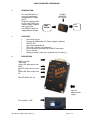
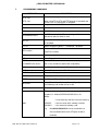
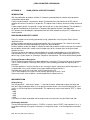
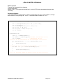
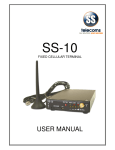
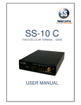
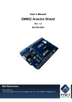
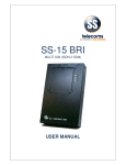
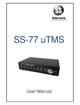
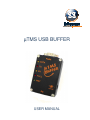
µTMS USB BUFFER USER MANUAL µTMS USB BUFFER USER MANUAL Revision history: Revision 01 New document 2009-06-30 CONTENTS 1. INTRODUCTION ....................................................................................................................3 2. FEATURES ............................................................................................................................3 3. DESCRIPTION .......................................................................................................................3 4. CONNECTION .......................................................................................................................4 5. DRIVER INSTALLATION........................................................................................................4 6. CHANGING THE COM PORT NUMBER ................................................................................4 7. PROGRAMMING COMMANDS ..............................................................................................5 8. TECHNICAL SPECIFICATIONS.............................................................................................6 9. CONTACT DETAILS ..............................................................................................................7 APPENDIX A: USING µTMS AS A SECURITY DONGLE ..........................................................8 DOC. NO: SST-µTMS USB-14 (REV. 01) Page 2 of 9 µTMS USB BUFFER USER MANUAL 1. INTRODUCTION The microTMS buffer is a small call record buffer fitted between the PABX and PC. The buffer ispowered from the PC and/or PABX lines. A power supply is optional and can be used if the PABX/PC does not supply adequate voltage. 2. PC USB PABX SERIAL FEATURES 3. POWER ADAPTOR (OPTIONAL) 32K or 64K versions Powered by PABX and/or PC (Power adaptor is optional) USB PC Port Non-volatile data buffering. LED status indicators for diagnostics. DB-9 male/female connectors for PABX/PC connection. Easy installation Beeper for memory read status and buffer 95% full warning DESCRIPTION PABX connector: - DB9 male Yellow LED: date receive from PABX Red LED: Data transmission to PC Yellow LED: Data receive from PC Red LED: Buffer 80% full Input for optional power supply PC connector: - USB DOC. NO: SST-µTMS USB-14 (REV. 01) Page 3 of 9 µTMS USB BUFFER USER MANUAL 4. CONNECTION PABX Connection Pin 2 Receive from PABX 7&4 Handshake to PABX 5 6&8 5. Pin Description Common ‘Ground’ signal Handshake from PABX DRIVER INSTALLATION Follow the steps below on installing the USB High Speed Serial Converter for the first time: 1. Plug in the USB cable into the USB port and Windows will detect the new hardware: SS Peripheral Run the Add New Hardware Wizard to assist you in setting up the new Device. 2. Insert the USB High Speed Serial Converter driver diskette into the floppy drive and click Next to continue: a. Select Search for the best driver for your device and click Next. b. Select Specify a location and click Browse. Change the folder of your floppy drive (e.g. A:\) and click OK. c. Double check the directory that Windows prompts. Click Next. d. Windows will detect the driver (FTDIBUS.inf) and show the USB High Speed Serial Converter. Click NEXT to continue until installation is complete. e. Click NEXT to continue and let Windows copy the needed files to your hard disk. f. Follow further instructions for installing the USB serial port. g. Click Finish when installation is complete. f. After installing, the System will generate an additional COM Port, USB to Serial Port (e.g. COM3) for the connection to RS232 Serial Device. 6. CHANGING THE COM PORT NUMBER 1. a. b. c. It is possible to change the COM port number for the USB serial port: From DeviceManager, select "View devices by type", then "Ports (COM & LPT)". Select the USB serial port and click Properties. Select the "Port Settings" tab, then click Advanced. Choose the required COM port number from the list and click OK DOC. NO: SST-µTMS USB-14 (REV. 01) Page 4 of 9 µTMS USB BUFFER USER MANUAL 7. PROGRAMMING COMMANDS INSTRUCTION STX <hh> DESCRIPTION Where hh is a 2 digit hex number. S<enter> When set to FF the STX and ETX behavior is turned off and normal <CR> line termination is accepted. Request a record in ASCII DUMP<enter> Dump all stored data SB baudrate<enter> Set PABX baud rate ETX <hh> SP baudrate<enter> UC <n> LF <n> SD n<enter> Set PC baud rate. Note: The new settings will be operational after the buffer is reset. Converts lowercase to uppercase. 1 = enabled, 0 = disabled Stores multiple line feeds. 1 = enabled, 0 = disabled n = 1 enable Date/Time insertion; n = 0 disable Date/Time insertion YY n<enter> Store Year if n = 1 YC n<enter> Store Century if n = 1 TIME Sets the Time. Note: This command has no purpose YYMMDDhhmm<enter> and is only included for back wards compatibility SAD n<enter> n = 1 Enable AutoDump; n = 0 Disable AutoDump SAT nn<enter> Set AutoDump timer to nn* 50 milliseconds CLEAR<enter> Clear the memory and reset SYS<enter> Display system information BEEP n<enter> n = 0 Beeper Off, n = 1 Beeper On HI<enter> VER<enter> Output Product Info, Maximum Memory Capacity, Used Memory and number of lines used. Display Software Version number Displays buffer capacity and used memory. Response is: MstatccSSSSSSccUUUUUU<cr><lf> Where: MM cc - is used internally and have no useful meaning. SSSSSS - is the hex value of the memory installed. UUUUUU - is the amount of memory used. e.g. Mstat0000800000000101 means that buffer has 32k ram fitted and there are 257 bytes of data in the buffer DOC. NO: SST-µTMS USB-14 (REV. 01) Page 5 of 9 µTMS USB BUFFER USER MANUAL 8. TECHNICAL SPECIFICATIONS LED indicators Connectors Current Firmware Version Diagnostics: PC Tx & Rx, 80% buffer full, PABX DATA, Watch Dog Timer PC Connection: USB PABX Connection: 9 way D-type male Rev:1.08 Storage medium Non-volatile Storage capacity 32K or 64K Setup storage Non-volatile set-up data storage Compatibility Compatible with most PABX units Required voltage Voltage supplied by PABX/PC PABX baud rate Software settable (Bd) 300, 600, 1200, 2400, 4800, 9600 PC baud rate Software settable (Bd) 300, 600, 1200, 2400, 4800, 9600 Time stamping of call records and events Data compression, typical ratio 2.5:1 Data storage Warning beeper at 95% full DTR enabled dumping of records ASCII handshake protocol Fully error corrected proprietary protocol DOC. NO: SST-µTMS USB-14 (REV. 01) Page 6 of 9 µTMS USB BUFFER USER MANUAL 9. CONTACT DETAILS Office: 23 Botha Avenue Lyttelton Manor Pretoria, Gauteng South Africa Tel: +27 12 664 4644 Fax: +27 86 614 5625 E-mail: [email protected] Postal address: Postnet Suite 48 Private Bag x 1015 Lyttelton, 0140 Pretoria, Gauteng South Africa Sales Support: South Africa E-mail: [email protected] United Kingdom E-mail: [email protected] Technical Support: E-mail: [email protected] DOC. NO: SST-µTMS USB-14 (REV. 01) Page 7 of 9 µTMS USB BUFFER USER MANUAL APPENDIX A: USING µTMS AS A SECURITY DONGLE INTRODUCTION With the proliferation of software solutions it is becoming commonplace for software to be pirated or used without authorisation. A fairly standard solution is to provide a 'dongle' (hardware device) that attaches to the PC and the software will not run if the device is not present. This obvious lock is often a source of irritation to the end user. A more elegant solution is to provide a 'useful' device that acts as the security dongle. The data buffer is an obvious candidate for the task where a Telephone Management System is the application. SS Telecoms have developed a simple protocol that will allow software to verify that it is attached to a matching buffer. DISCUSSION ON SECURITY ISSUES There is a simple level of security provided by having a data buffer in the first place. Pitfalls can be identified such as Another hardware manufacturer can develop a buffer with a similar protocol. This means that it will be possible to hijack the software package by using these alternate buffers Another software vendor can adapt his software to work with the buffers and thus take over the installed base of buffers allowing this vendor a much cheaper entry to this customer than the original vendor Solution to issues The basic solution to the problems outlined above has already needed addressing in the GSM arena. Authentication of users is vital to ensure that billing is accurate, for example. How do they do this? It is done using a system known as 'Challenge / Response' authentication. This will be outlined briefly below. Challenge Response Description The PC software and the Buffer have both loaded with a secret key. This key can be up to 16 characters The PC sends the buffer a challenge consisting of a short randomly generated message of up to 10 characters. The Buffer performs a 'hashing' function on this message using the secret key as part of the process. It is not possible using a small number of messages to determine what the key is. The buffer then sends the result of the 'hashing' function to the PC. The PC then compares this to the result of internally generating the 'hash' result If the results match, then the buffer is authenticated and the software will run. IMPLEMENTATION Setting the key Use the command '~ nnkk<enter>' where '~' is the tilde character, followed by a space character and then the 2 digit hexadecimal offset ('nn') for the key character which is also sent hexadecimal ('kk') and <enter> is the Carriage Return character 0x0D. The sequence to set the secret code to 'TEST' is shown below: ~ 0054 ~ 0145 ~ 0253 ~ 0354 The process has been automated and the code can be set and tested using the 'Buffer Lock' tool. Challenging the buffer The command to challenge the buffer is: 'CODErrr..rrr<enter>' where 'CODE' is the command, 'rrr..rrr' is the random challenge string up to 10 characters in length and <enter> is the Carriage Return character 0x0D. DOC. NO: SST-µTMS USB-14 (REV. 01) Page 8 of 9 µTMS USB BUFFER USER MANUAL Buffer response The buffer will respond with the following: CODE: hhhh<enter> Where 'CODE: ' is the response text and 'hhhh' is a 16 bit CRC for the submitted challenge and the secret key. Response validation In the code below the variable CRC is a 16 bit unsigned integer and char is 8 bit. CmdBuf is the input buffer where the string starting with 'CODE: ' is stored and CmdPtr indexes the 1st 'h'. void CalcCrc(unsigned char ser_data) { crc = (unsigned char)(crc >> 8) | (crc << 8); crc ^= ser_data; crc ^= (unsigned char)(crc & 0xff) >> 4; crc ^= (crc << 8) << 4; crc ^= ((crc & 0xff) << 4) << 1; crc &= 0xFFFF; } void mfCode(void) { char * p = &CmdBuf[CmdPtr]; int retCrc = HexToInt(p,4); //convert the hex data to int crc = 0xFFFF; //initialise the crc //======== do the calculation on the challenge ============= for (unsigned int i = 0; i < strlen(test); i++) { CalcCrc(test[i]); } //======== do the calculation on the UserKey ============= for (int i = 0; i < strlen(SecretKey); i++) { CalcCrc(SecretKry[i]); } //==== crc should be equal to retCrc if all is well ========== } DOC. NO: SST-µTMS USB-14 (REV. 01) Page 9 of 9