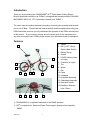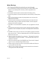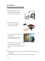
1
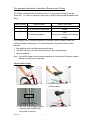
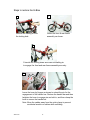
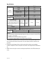
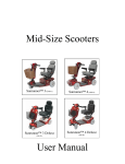
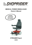
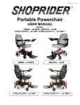
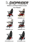
®
APT Power Assist Folding Electric Bicycle
USER MANUAL
Model: SFB-18
Table of Contents
Introduction…………………………………………………………...3
Features……………………………………………………………….3
Safety Warnings…………………………………………….………..4
User Guidance……..……………………………………………...5~7
Batteries and Charging…………………………………….…....8~11
Steps to fold the E-Bike………………………………………..12~13
Steps to restore the E-Bike……………………………………14~15
Troubleshooting……………………………………….….………..16
Specifications………………………………………………….…….17
Disclaimer……………………………….…………………………...18
2008/4/30
2
Introduction
Thank you for purchasing the SUNRUNNER® APT® Power Assist Folding Electric
Bicycle (hereinafter referred to as “E-Bike”) is designed and manufactured by PIHSIANG
MACHINERY MFG. CO., LTD. (hereinafter referred to as “PMMC”).
The user’s manual contains important information concerning the operation and the safe
use of your E-Bike. Please read this manual carefully and thoroughly before riding your
E-Bike and make sure that you fully understand the operation of the E-Bike as instructed
in this manual. If you have any queries about the spare parts for the maintenance or
any other concerns of your E-Bike, please contact your authorized dealer for assistance.
Features
1. Saddle
2. ON (I) -OFF-ON (II)
Switch (Main Switch)
1
6
8
7
9
11
15
13
10
12
3. Battery Gauge
4. Handle
5. LiFePO4 Battery Case
(w/ Light)
6.
7.
8.
9.
Controller (w/ Light)
Tire
Spoke
Rim
10. Pedal
11. Kickstand
12. Hub Motor Assembly
13. Chainwheel Assembly
14. Gear-shift Handle
15. Derailleur (Shimano
Inter-3 Gear)
4
5
3
2
14
※ SUNRUNNER® is a registered trademark of the PMMC products.
※ APT® is registered for “Advanced Power Technologies” developed and owned by
PMMC.
2008/4/30
3
Safety Warnings
1. Do not operate the E-Bike before reading this user manual thoroughly.
2. Do not disassemble the battery case and modify the unit without PMMC written
approval, or your warranty will be void and you will be responsible for the
modification.
3. Front basket is optional, and the maximum load for the basket is 4.4 lbs.
4. Check the tire pressure of front and rear wheel to be around 50PSI (or 3.5bar) before
riding.
5. Make sure that the battery has been fully charged before use, and remove the
charger after fully charged.
6. Check all electrical connections and mechanical parts are securely locked and
fastened before using your E-Bike, and check all cables, connector plugs and
sockets must be dry and undamaged.
7. The E-Bike is not recommended for competition, stunt, any aggressive or off-road
riding.
8. The performance and mileage of the unit will be varied with the battery condition,
temperature, terrain, wind speed, tire pressure, rider weight and the maintenance,
etc.
9. The E-Bike is able to sense your feet’s force on the pedal to provide you the assist
power once you ride it.
Before you depressing pedal on the E-Bike, please ensure
ahead of the road is clear.
10. Adjust the height of the saddle to fit your body size. Take heed of the maximum
height markings on the post of the saddle.
Your authorized dealer will give you
assistance if requested.
11. Refer to the instruction sheet of the SHIMANO Inter-3 Gear to switch 3 stages of
gears for a more comfortable riding at different slopes.
12. Always consult your doctor for advice on your physical condition and follow your
country’s traffic rules while riding.
13. Make sure that your dress and shoelaces must be secured from involvement to
moving parts of the E-Bike while riding.
2008/4/30
4
User Guidance
10 stages power assist output adjustment
1. Depress the pedal against a wall.
(Do not grab the front or rear brake
lever while depressing the pedal.)
2. Then, press the main switch to
either left (I) or right (II) position
while depressing the pedal.
3. After 10 seconds, the light of controller
will flash as below.
The 1st flash means the 1st stage.
The 2nd flash means the 2nd stage.
:
:
The 10th flash means the max. (the 10th stage)
output from the controller. Release
the pedal at once after selecting your desired
stage.
Note:
※ It’s recommended to set up at the 1st stage if riding on level ground frequently to save
battery charge.
※ It has been set up at the 10th stage for the default setting on your E-Bike.
2008/4/30
5
The operating instructions of derailleur (Shimano Inter-3 Gear)
The E-Bike is equipped with the Shimano Inter-3 (3-speed gear shifting) at the rear
wheel axle.
It is easy to change the gear ratio by shifting the gear-change handle while
riding.
Handle position
Riding Gradient
Speed / Gear Ratio
3
Level road
2
Level road with a slight slope
1
High
At a moderate gradient
Middle
Low
(To save your energy while climbing
a slope)
If the derailleur can not be performed with its intended function, please contact your
authorized dealer for adjustment. To shift the derailleur, the steps below should be
followed.
1. Stop pedaling before shifting the gears while riding.
2. Only shift one gear one time while switching the gear-change handle.
3. Resume pedaling.
Note : If you shift the gears without stopping pedaling, a clash may be heard due to gears
shifting over dynamic moving parts.
Adjust saddle height
2. Adjust the seat post to the
1. Loosen the clamp lever
desired position.
|||||||| MIN. INSERTION
3. Take heed of the maximum height
markings (MIN. INSERTION)
on the tube of the seat.
2008/4/30
6
4. Tighten the clamp lever.
Regular check for safety before riding
1. Check Tire Pressure
Check the tire pressure of front and rear wheel to be maintained at 50PSI (or 3.5Bar).
Check if the tire tread for wear and replace as needed.
2. Check Power Assist
The power assist will be cut off when one of handbrakes is engaged or the pedaling is
stopped.
3. Check Battery
Check if the battery case fits into the battery holder firmly and the LED Light of the
battery case lights up when the main switch is on at the II position.
Check if the battery is fully charged before use.
4. Check Motor and Control System
Must check the motor and control system are performed well.
5. General Inspection
Check for brake shoes wear and replace as necessary.
Check if the braking function is performed well.
Check if the front and rear wheels are performing smoothly.
Check if all connectors on E-Bike are firmly secured without any damage.
If you have any questions after checking, please refer to the solutions for trouble
shooting (page 16) or contact your authorized dealer for inspection and maintenance.
Cautions for Riding
˙ Always follow the county’s traffic rules while riding.
˙ Check the battery gauge if the charge is sufficient to keep the power assist for your
riding.
˙ Do not keep riding your E-Bike if any problem has occurred. Refer to the solutions for
trouble shooting (page 16) or contact your authorized dealer for further inspection
and maintenance. Ensure to use the spare parts supplied by PMMC for
replacement.
Other Keys to Lifespan
The lifetime of your E-Bike will be adversely affected by exposures to aggressive road
conditions, dirt, rain, water or salt spray. Be sure your E-Bike, including the battery case,
are protected well for transportation and store your E-Bike indoors when not in use.
These steps are essential to prolong the lifespan of product.
2008/4/30
7
Battery and Charging
Dismounting Battery Case
1. Before sliding out the battery
case, make sure the battery
holder latch is at the position
as shown.
2. Switch the key to horizontal
(flat) position. Depress the key
to release the lock and use the
other hand to push the battery
case out from the battery
holder.
3. Remove the battery case.
Mounting Battery Case
1. Please secure the battery case holder with one hand
and slide the battery case onto the rail all the way down
to lock the battery case as shown.
Note: If the battery case can be removed without
depressing the key, this means that the battery
case has not been properly locked. Repeat the
above procedures again.
2. The battery case will be locked
and can’t be removed when the
key is in the vertical position.
2008/4/30
8
Battery and Charging
Steps to charge the Battery
1. Switch your E-Bike off on the main switch of
battery case.
2. Dismount the battery case and then place it at a
Power Plug
Charger Plug
ventilated place to be charging.
3. Swivel the charging port cover of battery case and
then connect the charger plug of the charger.
4. Plug the power plug of the charger into secure
power source to start charging battery.
Note: Ensure that the charger plug is dry and
securely connected to the charger port of
battery case.
Operating Instruction
1. Must assure the input voltage is between 100V~240V.
2. Must assure the battery to be charged is a LiFePO4 (Lithium Iron Phosphate Based)
Battery Pack supplied by PMMC.
3. Make sure the power cord, battery cable, and battery terminals are in good condition.
4. Make sure the connecting battery rating is the same as the charger output voltage
(24V).
5. While charging, the charging LED will display a RED light. When the light turns
GREEN, the battery is fully charged.
Charger LED Indication
1. LED (GREEN) – Power On, when not connected to the batteries.
2. LED (RED) – Charging
3. LED (GREEN) – Fully Charged, when connected to the batteries.
Trouble Shooting
1. If the LED light is “OFF” all the time while charging:
Check if the power connections are in good condition. If the LED light is still off all the
time while charging, the battery charger may be malfunctioning.
Please consult your authorized dealer for further assistance.
2. If the LED light does not switch from GREEN to RED when the charging process
begins:
Check if the connection of the battery polarity is correct.
Check if the connection between charger plug and charging port of the battery is
correct.
Check if the battery case is already fully charged.
Check if the battery is functioned properly.
3. The charging time continues for a long duration (Irregular):
Check if the battery is out of order or aged.
4. The battery overheats:
2008/4/30
9
Check the battery specification or consult your authorized dealer. Stop charging
immediately and check if there is a problem with the charger or the batteries.
Caution
1. Make sure the DC output connected to the battery to be charged is at the rated
voltage, or it may cause unexpected danger or damage.
2. For your safety, do not charge the batteries for longer than 24 hours.
3. Do not expose the charger to the rain, water or a humid place; Do not use the battery
charger near flammable articles or in unventilated places.
4. For your safety, do not short circuit output plug, or it may cause unexpected danger or
damage.
5. Use the specified charger only for LiFePO4 (Lithium Iron Phosphate Based) Battery
Pack (24V) supplied by PMMC.
6. Always use the battery charger and power cord supplied by PMMC.
7. Before plugging in the power cord of the charger, please confirm that the local power
supply corresponds with the requirement of the charger.
8. The manufacturer will not be responsible for any damage or injury due to improper or
unsafe use of the battery charger.
2008/4/30
10
Battery Case Features
Charging Port
Cover
˙Main Switch Function
Charging Port
Switch
Depressed
Function
Position
I
II
о
LED Light of
controller is lit up.
Both LED Lights
on controller and
battery case are
lit up.
Start the
function of
Power Assist
by pedaling.
Battery Gauge
Main Switch
Power off
The LED Light on the controller and battery case
utilizes the 1W Warm White LED Light which is
green energy and provides moderate light in the
dark.
˙The battery gauge with 4 battery level indicators
precisely indicate the remaining charge of the
battery. As the last battery indicator light starts
Warm White LED Light
on Battery Case
flashing, the rider can continue to ride the E-Bike
for approx. 1.2 miles further.
˙Swivel the cover from the charging port to charge
the battery. After fully charged, swivel the
cover back to the charging port to prevent water
and dust from getting into the socket.
˙The battery case is not allowed to be disassembled
and should be prevented from dipping into water
Warm White LED Light
on Controller
and exposing to fire.
˙The portable battery case weighs 3.1 lbs can be
placed in a carrying bag attached with each E-Bike and
may be used for individual lightening system, same as
a flashlight device. With different capacity of the battery,
the warm white LED light can be lasted for 3~6 days.
˙The threading hole is available underneath the battery
case for the connection to other devices, such as
camera’s stand as shown.
2008/4/30
11
Battery Case mounted
on camera’s stand
Steps to fold the E-Bike
1
Refer to the instruction for Dismounting Battery Case to
remove the battery case.
3
2
Loosen the clamp lever to remove the saddle.
Note: Keep the battery case and the saddle in
a safe place after removed from the E-Bike.
4
5
Pull the trigger of the pedal and fold the
pedal simultaneously. Repeat the same
steps for the other side of the pedal.
Lower the mudguard by
loosening the tighten knob.
2008/4/30
12
7
6
Fold the front & rear
frame assembly as shown.
Pull out the safety pin from the
locking hole.
8
Insert the safety pin into the
locking holes to engage the
front and rear frame assembly.
9
10
Loosen and then lower the lever to retreat the pin to release the clamping
of the handle bar. Keep the crank-pedals on the level while folding the
handle bar. Fold the handle bar downward toward the same side of the
kickstand and beyond the level of crank-pedals.
Note: Move the cables away from the quick-clamp to prevent accidental
Scratch on cables while folding.
11
The folding steps are completed.
2008/4/30
13
Steps to restore the E-Bike
2
1
Unfold the front & rear frame
assembly as shown.
Remove the safety pin from
the locking hole.
3
Coincide the locking holes and insert the safety pin
to engage the front and rear frame assembly securely.
4
3
1
2
Lower the lever by fingers as shown to retreat the pin for the
engagement of the handle bar. Restore the handle bar and then
heighten the lever to engage pin and slot in, and then clamp the
lever to secure the handle bar.
Note: Move the cables away from the quick-clamp to prevent
accidental scratch on cables while unfolding.
2008/4/30
14
5
6
Adjust the tighten knob
to fasten the mudguard.
Note: Follow the same steps
while installing the
mudguard on a new unit.
Pull the trigger of the pedal and unfold
the pedal simultaneously. Repeat the
same steps on the other side of the pedal.
8
7
Refer to the instruction for Mounting
Battery Case to be mounted.
Install the saddle and adjust
it to the desired height and
then tighten the clamp lever.
Note: For your safety, do not
set the saddle height
exceeding the bottom line
on the seat post.
9
The unfolding steps are completed.
2008/4/30
15
Trouble shooting
PROBLEM
POSSIBLE CAUSE
SOLUTION
Battery case with a
Battery case has not been
loosening issue. (such totally locked onto the
as, battery case could be battery holder firmly.
removed when the key
Follow the instruction to dismount
then mount battery case again to
check if battery case can not be
removed without depressing the
on battery case is not
depressed.)
key.
Battery gauge LEDs with Battery case has a low
Check if battery case has been
no display when power charge or a loosening issue. fully charged before use. To check
on.
the solution as above if the battery
case has a loosening issue.
Power assist fails to
perform its intended
Controller may go to sleep
mode to preserve battery
Switch power off and then back on
to remove from sleep.
function when pedaling. charge after being idle for Check handbrakes are totally
few minutes.
disengaged when the levers have
Or, one of handbrakes fails been released.
to restore to its disengaged
position.
Power assist function
Battery case with an empty As the last battery indicator light
discontinued when
riding.
charge.
start flashing then the battery case
must be recharged as soon as
possible, or the power assist will be
discontinued after approximately
1.2 Mi further.
Poor traveling range
Frequent riding on
Decrease chance to ride on
gradients, poor tire
pressure, battery case with
insufficient charge, or
battery aging, etc.
gradients to check if a longer range
is acquired, fill up tire pressure to
50 PSI, fully charge the battery
daily after use, or replace a new
battery case, etc.
Unusual motor/gear
Check if any foreign object Clean up obstacles around the
sound (noise)
existed on wheels or motor. wheels and motor.
※ Note : Must use the genuine SUNRUNNER charger dedicated for C-LiFePO4 Battery
Case to be charged.
※ Please contact your authorized dealer if the above solution has been checked and
the problem is still existed.
2008/4/30
16
Specification
Model
SFB-18
Length
In
54.5
Width
In
24.4
Saddle Height
In
27.1
Handlebar Height
In
41.3
Tire Size
In
18
Wheels Center Distance
In
36.8
lb
38.6
Overall
Dimension
Total Weight (w/o Battery Case)
®
Type-Envirofriendly , Capacity
Battery
Optional (Capacity / Weight)
C-LiFePO4 , 3.5 / 5 Ah
3.5Ah / 3.2 lbs
5Ah / 3.4 lbs
17.4 mi
21.1 mi
Reference Range
(on the level ground without wind) Set to the 1st 187.4 lbs
The output power assist from the
stage of
(a rider’s
controller can be set up from 1-10 power assist weight)
stage for riders.
Derailleur
Power Assist Driving Wheel
Hub Motor Model
Charger
SHIMANO NEXUS INTER-3
Front Wheel Drive
Brush Motor with reduction gear (24 V)
Type (Dedicated for C-LiFePO4 Battery)
2A
Charging Time
25 min~2.5 hrs
Remarks:
1. As the last battery indicator light starts flashing, the rider can continue to ride the E-Bike
for approx. 1.2 mi further.
2. Go-Button Kit and Throttle Handle Kit are optional.
3. The maximum weight capacity of the E-Bike is around 198.4 lbs.
1. The maintenance guarantee period of this product except consuming parts begins on the
day of purchase and ends at one year later. Only the original purchaser is entitled to the
guarantee.
2. Performance and mileages of the unit will be varied with the factors, such as battery
condition, temperature, terrain, wind speed, tire pressure, rider weight and the maintenance,
etc.
3. PMMC reserves the right to revise the wording and specification of the E-Bike without prior
notice.
2008/4/30
17
APT○ Power Assist Folding Electric Bicycle
R
DISCLAIMER
Congratulations on your purchase of SUNRUNNER® APT® Power Assist Folding Electric
Bicycle.
This APT® Power Assist Folding Electric Bicycle is not intended to be used by individuals
with physical limitations that could prevent the user from operating the APT® Power
Assist Folding Electric Bicycle safely. PMMC disclaims all responsibility for any
personal injury or property damage, which may occur as a result of improper or unsafe
use of its products. Mechanical or electrical defects will be dealt with on a contingency
liability basis.
Warranty is only valid when genuine SUNRUNNER parts are used. All modifications on
the APT® Power Assist Folding Electric Bicycle, unless approved and authorized by
SUNRUNNER will automatically invalidate the warranties. Standard warranty does not
extend to consumable items and parties other than the original purchaser.
The preceding guidelines are intended to assist you in the safe operation of this APT®
Power Assist Folding Electric Bicycle. Should you have any questions about the correct
operation of the APT® Power Assist Folding Electric Bicycle, please contact your
authorized dealers.
Model Name – SUNRUNNER SFB-18
Provider Stamp
Serial No.: _______________________
P/N300905-25
2008/4/30
18