1
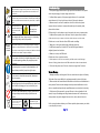
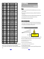
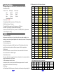
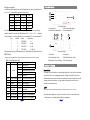
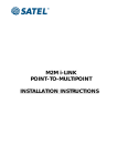
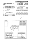
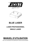
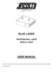
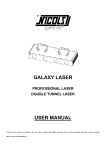
Ariana
RGB LASER SHOW SYSTEM
User's Manual
Read this manual before using. Do not attempt to open the housing
or repair this device by yourself without contacting us!
DMX Address Chart
General instructions
This chart lists the DMX dipswitch setting for DMX address 1 through 511. Follow the
Unpacking:
instructions below to configure fixture dipswitches with your desired DMX address.
Thank you for purchasing this product. Please read user guide for safety and before using
DMX Address Quick Reference Chart
DipSwitch Position
the product. Keep this manual for future reference. This product can create perfect laser
programs and effects since it has passed a series of strict tests before delivery. Please check
the attachments listed on the page after opening the box. Immediately upon receiving
a fixture, carefully unpack the box. Check the box contents to ensure that all parts are present
and that they are in good condition. If any part appears damaged from shipping, or if the
box shows signs of mishandling, notify the shipper immediately. In addition, retain the box
and all the packing material for inspection. In any event, save the box and all packing material
because, in the case that you have to return the fixture to the factory, you will have to do so in
its original box, with its original packing.
1. Laser Light:
1PCS
2. Power Cable:
1PCS
3. User Guide:
1PCS
Safety Notice:
Please read the following notes carefully because they include important safety information
about the installation,usage and maintenance of this product. It is important to read all these
notes before starting to work with this product.
Lasers can be hazardous and have unique safety considerations. Permanent eye injury
and blindness is possible if lasers are used incorrectly. Pay close attention to each safety
REMARK and WARNING statement in the user manual. Read all instructions carefully.
There are no user serviceable parts inside the light. Any reference to servicing
this unit you may find from now on in this User Manual will only apply to
properly certified technicians. Do not open the housing or attempt any repairs
unless you are a trained professional.
Please refer to all applicable local codes and regulations for
proper installation of the light.
DipSwitch Position
DMX Address
Page 12
Keep this manual for future consultation. If you sell the light to
another user, make sure that they also receive this manual.
Page 1
Avoid direct eye exposure to the light source while the fixture is on.
Always disconnect the light from its power source before servicing.
Always connect the light to a grounded circuit to avoid the risk of
electrocution.
This product is for indoor use only! Use only in dry locations. Keep
this device away from rain and moisture, excessive heat, humidity and
dust. Do not allow contact with water or any other fluids, or metallic
objects.
Make sure there are no
Please prevent this
flammable materials close
light away from
to the fixture(s) while
electrical
shock
operating.
When hanging this fixture, always secure it to a fastening
device using a safety cable (not provided).
Power
110V 240V
Ground
Always make sure that you are connecting the light to the proper
voltage, as per the specifications in this manual or on the product's
sticker. Never connect the light to a dimmer pack. Make sure that the
power cable is not cracked, crimped or damaged.
The maximum ambient temperature (Ta) is 104 F (40 C).
Do not operate the fixture at a higher temperature. In case
of a serious operating problem, stop using this product
immediately!
Use cleaning tissue to remove the dust absorbed on the
external lenses periodically to optimize light output.
Troubleshooting
1. If the power supply indicator doesn't light up and the laser doesn't work, please
check the power supply, the input voltage and the fuse.
2. In Stand-Alone operation, if the power supply indicator is lit up and sound
active indicator isn't lit up, but the laser is shut off this may be because:
A. Because sound is too small to make laser shut off in sound active, please
increase the music volume or increase audio sensitivity with sensitivity knob,
please check as below.
B. Please check if unit has been set up in slave mode, then set up in master mode.
3. In Master-Slave operation, slave unit doesn't function, please check as below.
A. Make sure there's only one master in the chain, and the others are set in slave mode.
B. Make sure to control the unit without DMX console controlling.
C. Make sure to take a good quality power cable and connection.
4. In DMX mode operation, the laser is OFF and the DMX signal indicator is
unlighted, please check as below.
A. Make sure to set up the DMX mode.
B. Make sure to have a good connection.
5. In DMX operation, the unit can’t be controlled by the DMX console, but the DMX signal
indicator is flashing, please make sure the DMX console and unit have the same channel.
6. If the unit fails, please turn off the unit, then turn on again after 5 minutes.
Warranty Warnings:
Do not remove or break the warranty label, otherwise it
voids the warranty.
1. Damages caused by the disregard of this user manual are not subject to Warranty.
Always replace with the exact same type fuse, replacement
with anything other than the specified fuse can cause fire or
electric shock and damage your unit, and will void your
manufactures warranty.
There are no serviceable parts in the light. Please have all
servicing and adjustments made by a qualified service
engineer.
2. Please consider that unauthorized modifications on the device are forbidden due to
To protect the
environment, recycle
packing material wherever
possible.
Don’t throw this product away just
as general trash, please dispose of
this product following the
abandoned electronic product
regulations in your country.
Page 2
The dealer will not accept liability for any damage caused by misuse of the item.
safety reasons. Please note that damages caused by manual modifications on the
device or unauthorized operation by unqualified persons are not subject to warranty.
3. If this device will be operated in any way different to the one described in this
manual, it may suffer damages and the guarantee becomes void. Furthermore, any
other operation may lead to dangers like short-circuit, burns, electric shock, etc.
If after trying the above solutions you still have a problem, please contact your dealer
or our company for service.
Page 11
Laser Safety Warnings
ch8 value Color
ch8 value Color
ch8 value Color
ch8 value Color
6~7
yellow/Y
70~71 PCR
134~135
WPYB
198~199
WPCYR
8~9
blue/B
72~73 PCG
136~137
PCYB
200~201
WPCYG
10~11 red/B
74~75 PYB
138~139
PCYR
202~203
PCYBR
12~13 green
76~77 CYB
140~141
PCYG
204~205
PCYBG
Caution
14~15 wP
77~79 CYR
142~143
PCBR
206~207
PCBRG
* Avoid direct eye contact with laser light. Never intentionally expose your eyes or others to
16~17 wC
80~81 CYG
144~145
PCBG
208~209
CYBRG
18~19 wY
82~83 CBR
146~147
CYBR
210~211
CYBRW
20~21 PC
84~85 CBW
148~149
CYBG
212~213
CYBGW
22~23 PY
86~87 YBR
150~151
CYRG
214~215
YBRGW
24~25 PB
88~89 YBG
152~153
CYRW
216~217
YBRGP
26~27 CY
90~91 YBW
154~155
CYRB
218~219
YBRWP
28~29 CB
92~93 YCW
156~157
YBRG
220~221
BRGWP
30~31 CR
94~95 YPR
158~159
YBRW
222~223
BRGWC
NON-INTERLOCKED HOUSING WARNING
32~33 YB
96~97
160~161
YBRP
224~225
BRWPC
*This unit contains high power laser devices internally. Do not open the laser housing, due to
34~35 YR
98~99 BRP
162~163
YBWC
226~227
RGWPC
potential exposure to unsafe levels of laser radiation. The laser power levels accessible if the
36~37 YG
100~101
BRW
164~165
YBPC
228~229
RGWPY
unit is opened can cause instant blindness, skin burns and fires.
38~39 BR
102~103
BGP
166~167 BRGW
230~231
RGWCY
40~41 BG
104~105
BGW
168~169 BRGP
232~233
GWPCB
42~43 BW
106~107
RGC
170~171 BRGC
234~235
GWPYB
44~45 RG
108~109
RGP
172~173 BRWP
236~237
GPCYR
46~47 RP
110~111
RGW
174~175 BRWC
238~239
WPCYBR
48~49 RW
112~114
RWC
176~177 RGWP
240~241
PCYBRG
50~51 GC
114~115
RWY
178~179 RGWC
242~243
CYBRGW
52~53 GP
116~117
GWC
180~181 RGWY
244~245
YBRGWP
54~55 GW
118~119
GWY
182~183 RGPC
246~247
BRGWPC
56~57 WPC
120~121
GPY
184~185 RGPY
248~249
RGWPCY
taken to assess the likelihood of any reflective surfaces (such as high windows, chrome bars
58~59 WPY
122~123
GBC
186~187 GWPY
250~251
GWPCYB
etc) bouncing stray beams back down into the audience.
60~61 WPB
124~125
GRY
188~189 GWPB
252~253
WPCYBRG
*Use a safety chain when flying the unit.
62~63 WPR
126~127
WPCY
190~191 GWPR
254~255
moving WPCYBRG
*Make sure the correct power output and plug are used.
BRG
Potential laser injury hazard exists with this product! Read these Instructions carefully, which
include important information about installation, safe use and service!
direct laser radiation.
*This laser product can potentially cause instant eye injury or blindness if laser light directly
strikes the eyes.
*It is illegal and dangerous to shine this laser into audience areas, where the audience or other
personnel could get direct laser beams or bright reflections into their eyes.
*It is a US Federal offense to shine any laser at aircraft.
Installation
AVOID DIRECT EYE
CONTACT!
*Laser effects projected 3 meters (9.8 ft) above the audience are eye safe. A survey should be
1. There are 52 static patterns, the sizes of the patterns are adjustable by changing the
* Ground the yellow/green conductor to earth to avoid electric shock.
DMX value. There are 52 dynamic patterns, whose sizes are non-adjustable.
* Do not shoot the beams to the audience!
2.Only circle pattern has color segment function, it needs to operate with both CH8 and
*Do not look directly into the laser aperture once the laser light is ON. Please pay attention to
CH9.
the Laser Danger Warning Label!
Page 10
Page 3
Technical Specification
CH2 Parameter Chart For Patterns Selection
1. Voltage: bi-voltage 110V -220V-250V AC, 50HZ-60HZ/ Fuse: 2A/250V
2. Rated Power: 30W
3. Laser: Color
Wavelength
Power output
DMX valueStatic patterns
Dynamic patterns DMX valueStatic patterns
Dynamic patterns
0~4
one circle
5~9
empty circle empty circle to big 135~139 dot triangle 2vertical line move
circle to big
130~134 triangle 2
two hori dot line move
Red
650nm
100mW
10~14
dot circle
dot circle to big
140~144 chiasma line vert-dot line move
Green
532nm
30mW
15~19
scan circle
scan circle to big
145~149 chia-dot line two vertical line move
Blue
470nm
100mW
20~24
two circle
circle roll
150~154 square
two vert-dot line move
25~29
three circle
empty circle roll
155~159 dot square
square extend
4. Laser class: Class IIIB
30~34
four circle
dot circle roll
160~164 rectangle
dot square extend
5. Working Modes: DMX, Sound Active, AUTO, Master-Slave
35~39
two emp-circle
circle turn
165~169 dot rectanglepentagon extend
6. DMX Control Channel: 7 channels
40~44
two dot circledot circle to add
170~174 many hori-linesquare turn
7. Graphics & Effects: more than 100 patterns, over 300 effects
45~49
hor-extend line
circle jump
175~179 many vert-linepentagon turn
8. Interface: 3 pins XLR jack for DMX or Maser-Slave linking
50~54
hori-shrink linescan circle extend 180~184 tetragon 1
line scan
9. inner box: 310*245*170(0.013m³), carton: 515*330*382(0.065m³), 4pcs/carton
55~59
hori-flex line circle flash
185~189 tetragon 2
dot line scan
10. N.W.: 1.8kg, G.W: 2.4Kg
60~64
horizontal lineempty circle roll
190~194 pentagon 1 wave turn
65~69
hori-dot line two circle turn
195~199 pentagon 2 dot wave turn
1. Seven-color laser light
70~74
vertical line
200~204 pentagon 3 wave flowing
Includes seven-color effects as red, green, blue, yellow, cyan, purple,and white. It can
75~79
hori-dot line diagonal jump
205~209 wave line 1
dot wave flowing
combine to create rich and dynamic patterns at the same time, more than 100 laser patterns,
80~84
45° diagonal sector to big
210~214 wave line 2
sine wave
over 1000 laser effects.
85~89
dot diagonal dot sector to big
215~219 wave line 3
dot sine wave
2. Various working modes
90~94
two hori-line diagonal move
220~224 wave dot line tetragon turn
95~99
two hori-dot line
dot diagonal move 225~229 spirality line pentagon star 1 turn
Mixed white: 230mW
Features
Includes four working modes as DMX, Sound Active, AUTO and Master-Slave Control
four circle turn
mode, different working modes has different program for different applications.
100~104 two vert-line long sector round 230~234 welcome
3. DMX control
105~109 two vert-dot line
short sector round 235~239 horizontal dotsquare dot jump
The unit has 9 channels to control in DMX mode. The unit has BLACK OUT function.
110~114 V line
three line round
240~244 vertical dot bird fly
The uint will shut OFF if no DMX512 signal.
115~119 V dot line
hori line move
245~249 many dot 1 many dot jump 1
4. Master-Slave function
120~124 triangle 1
hori dot line move 250~254 square dot
The system allows links to many units (as slave unit) together to do synchro job without
125~129 dot triangle 1two hori line move
255
pentagon star 2 turn
V pattern move
many dot 2 many dot jump 2
console in sound active or AUTO mode.
5. LED indicating and shut-off function
CH8 Parameter Chart For Color Selection
In sound active mode, the unit's panel has LED indicating sound active. The unit will
ch8 value Color
ch8 value Color
ch8 value Color
ch8 value Color
shut off after 8 seconds when the music stops.
0~1
white/W
64~65 WPG
128~129
WPCB
192~193
GWCY
6. DPSS Laser
2~3
purple/P
66~67 PCY
130~131
WPCR
194~195
GWCB
Use Diode-Pumped Solid State green, red blue lasers, stable output and long working life.
4~5
cyan/C
68~69 PCB
132~133
WPCG
196~197
WPCYB
Page 4
Page 9
Front/Rear Panel
DMX address calculation
For DMX mode, DMX address from #1 to 9# dipswitches must be set, the address is set
from 1 to 511. Each dipswitch represents a binary value.
Dipswitch
Value
Dipswitch
2!
Value
#1
1
#6
#
#2
2
#7
#
#3
4
#8
3
1
4
128
#4
8
#9
256
#5
#
#10
DMX, Set to "0"
One unit has 5 channels, so each unit must be assigned 5 channels at least. We may
Front Panel Figure
1. Laser Aperture
2. Sound Active Microphone
3. Sound Active Indicator:Blue
4. Power Indicator:Red
assign 8 channels for one unit, then DMX address = 8*N + 1, N=0, 1, 2, 3 …… Example,
5
One loop address=1, two loop address=9, three loop address=17, four loop address=25
Loop
Address
Binary
Dipswitches
4
3
1
2
#1
1
1
100000000
2
9
100100000
#1+#4
3
17
100010000
#1+#5
4
25
100110000
#1+#4+#5
6
Rear Panel Figure
The dipswitches setting for DMX address see the " DMX Address Quick Reference Chart ".
DMX Control
1. Power Jack
2. Cooling Fan
The system only accepts the DMX512 signal of international standard to control the system.
3. Audio Sensitivity Knob
4. DMX Signal Indicator: Green
DMX Control Parameter Chart
Channel
Function
5. Dipswitches: Function Setting 6. DMX or Linking Jack
Value
0~49
50~99
CH1
CH2
Mode
Description
Close, laser OFF
Static patterns of DMX mode
Function & Setting
100~149 Dynamic patterns of DMX mode
Sound Active
150~199 Sound active mode
The change of the laser pattern is controlled by sound, that is, the rhythm of the sound
200~255 Auto mode
controls the effect of the changing laser pattern. Turning the sensitivity knob in the
clockwise direction to increase the fixture’s sensitivity to sound, the knob in the counter
CH7
Pattern selection 0~255
Position-X
0~255
Position-Y
0~255
Scanning speed
0~255
Dynamic pattens
0~255
play speed
Static pattern size 0~255
52 static/dynamic patterns
Adjust position-X
Adjust position-Y
0 is speedy, 255 is slow
0 is speedy, 255 is slow, has ten
grade speed
0 is small, 255 is big
CH8
Color Selection
0~255
RGBYCPW, 7 colors combinered
The mode allows a single unit to react to the beat of the music in the master mode.
CH9
Color Segment
0~255
Divide into 1 to 51 segment
1. Install the units in a suitable position (laying or appending).
CH3
CH4
CH5
CH6
Page 8
clockwise direction to decrease. The laser diode will automatically turn off after 8
seconds when the music stops.
AUTO
Auto cycles the built-in programs without being controlled externally. It has no laser OFF.
Page 5
2. Set dipswitch to select Sound Active or AUTO mode.
2. Use standard XLR microphone cable to chain your units together via the XLR connector
3. Turn on the unit power, the unit begins, reset, then the unit begins working.
on the rear of the units. For longer cable runs we suggest a terminator at the last fixture.
4. The unit will react to the low frequencies of music via the internal microphone.
3. Assign a DMX address to each of the units using dipswitches, see the "DMX Address
Adjust the audio sensitivity knob on the back of the unit to make the unit more or less
sensitive in sound active.The panel has an LED indicating sound active.
Quick Reference Chart".
Light No 1
Light No 2
Light No 3
Light No ….
Master-Slave Operation
This mode will allow you to link up to 32 units together without controller.
1. Install the units in a suitable position (laying or appending).
……...
2. Choose a unit to function as Master mode, set dipswitch to select Sound Active or
AUTO mode. The others must be set to Slave mode, set dipswitch to select Slave mode.
3. Use standard XLR microphone cable to chain your units together via the XLR connector
DMX Signal
1:MASTER: SOUND/AUTO/DMX
2:SLAVE
2:SLAVE
on the rear of the units. For longer cable runs we suggest a terminator at the last fixture.
4. Turn on the all units' power, the units begin, reset, then the unit begins working.
Cabling must have a male XLR connector on one end and a female XLR connector on the other end.
5. Use DMX console to control your units.
Notes:
1. DMX console can not be used in Master-Slave operation (Sound Active or AUTO mode ).
2. There should be only one master unit in Master-Slave operation.
DMX Control
The system only accepts the DMX512 signal of international standard to control the
system mode, the laser beam ON /OFF, running direction, running speed and twinkle
speed etc.
Caution: Do not allow contact between the common and the fixture's chassis ground.
Function setting
Grounding the common can cause a ground loop, and your fixture may perform erratically.
Uses dipswitches to assign a unit’s function: DMX/slave, or sound active, or AUTO mode.
Test cables with an ohm meter to verify correct polarity and to make sure the pins are
For the unit to use DMX mode, set the DMX address using dipswitch. Each dipswitch
not grounded or shorted to the shild or each other.
represents a binary value. See the “Function chart”.
4. Turn on all units' power, the units begin, reset, then the unit begins working.
The slave units will react the same as the master unit.
5. The units will react to the low frequencies of music via the internal microphone.
Adjust the audio sensitivity knob on the back of the master unit to make the unit more
or less sensitive in sound active.The panel has an LED indicating sound active.
Universal DMX Operation (DMX mode)
This mode allows you to use universal DMX-512 console to operate.
1. Install the units in a suitable position (laying or appending).
Page 6
Built-In Program Function Chart
Page 7