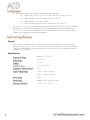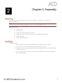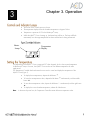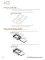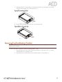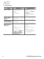
1
™ RNAscope®, and HybEZ™are trademarks or registered trademarks of Advanced Cell Diagnostics, Inc. All other trademarks belong to their respective owners. When describing a procedure for publication using this product, please refer to it as the ACD HybEZ™ Hybridization System (Cat. No. 310010 and Cat. No. 310013). Advanced Cell Diagnostics, Inc. reserves the right to change its products and services at any time to incorporate technological developments. This manual is subject to change without notice. Although this manual has been prepared with every precaution to ensure accuracy, Advanced Cell Diagnostics, Inc. assumes no liability for any errors, omissions, or for any damages resulting from the use of this information. © 2014. Advanced Cell Diagnostics, Inc. All rights reserved. Contents ................................................................................................... 5 ................................................................................................. 5 General ........................................................................................................ 6 Specifications............................................................................................... 6 Removing the Frame Assembly ................................................................ 13 Replacing the Frame Assembly................................................................. 14 3 Limited product warranty ........................................................................... 25 Returns ...................................................................................................... 25 Chapter 1. Product Information Before using this product, read and understand the information in Appendix C. Safety on page 23 in this document. IMPORTANT! We recommend reading the entire user manual before beginning any protocols. This user manual describes how to use the ACD HybEZ™ Hybridization System. Many staining assays that detect molecular markers in microscope-mounted biological specimens involve repeated incubation steps at elevated temperatures, where slides are held in a horizontal position that allow a small volume of reagents to incubate with the specimen. During incubation special measures have to be taken to prevent loss of reagent due to evaporation. The ACD HybEZ™ Hybridization System is an evaporation controlled incubator designed to conduct the hybridization and incubation steps in Advanced Cell Diagnostic’s proprietary RNAscope® assays. The HybEZ™ Humidity Control Tray and HybEZ™ Slide Rack included in the system allow batches of slides to be processed at the same time. The ACD HybEZ™ Hybridization System is compatible with other hybridization based assays or any assay step where a condition of high humidity with an elevated temperature is required. The ACD HybEZ™ Hybridization System contains the following components: HybEZ™ Oven (110 VAC, Cat. No. 310010; 220 VAC, Cat. No. 310013) HybEZ™ Humidity Control Tray with lid (Cat. No. 310012) HybEZ™ Slide Rack (Cat. No. 310014) HybEZ™ Humidifying Paper Pack with 15 sheets (Cat. No. 310015) The system can hold up to twenty standard microscope slides on the slide rack. The unit has an advanced PID temperature controller that provides stable and accurate chamber temperatures from ambient plus 10˚C to 75˚C. The unit utilizes a sealed tray to create a lasting humid environment for overnight runs or weekend runs, depending on the operating temperature. General This equipment is intended for indoor use and will meet performance specifications within the ambient temperature range of 10˚C to 75˚C, with maximum relative humidity of 80% (non-condensing). Installation Category II (transient voltages). Pollution Degree 2 in accordance with IEC 664. Suitable for operation at altitudes of up to 6500 feet. Specifications (Ambient +10˚C) to 75˚C 0˚C to 75˚C +/- 0.5˚C +/- 0.5˚C at 40˚C 0.1˚C 115V +/- 10%, 50/60 Hz 230V +/- 10%, 50/60 Hz 155W Ambient to 40˚C within 20 minutes 17 5/8” X 17 1/8” X 6” Chapter 2. Assembly Remove packing materials carefully, and retain for future shipment or storage of the unit. Inspect all materials for damage. IMPORTANT! Report all shipping damage to the carrier immediately. Shipping damage is covered by the carrier and repair/replacement for shipping damages must be coordinated through the carrier. Packs should contain: HybEZ™ Oven Power Line Cord HybEZ™ Hybridization System User Manual HybEZ™ Humidity Control Tray (includes a tray with gasket installed and lid) HybEZ™ Slide Rack HybEZ™ Humidifying Paper To install the system: 1. Place the HybEZ™ Oven on a flat and stable surface, preferably away from drafts. 2. Fit the power line cord into the IEC power socket on the rear of the unit. 3. Plug power cord into a power supply that matches the voltage listed on the serial number label on the rear of the unit. 4. Prior to operation remove the tape inside the heating chamber that holds the frame assembly in place during shipping. Chapter 3. Operation The Power Switch controls power to the unit. The temperature display shows the chamber temperature in degrees Celsius. Temperature is preset at 40˚C for the RNAscope® Assay. While the HybEZ™ Oven is heating up, the heater lamp will be on. The lamp will flash intermittently once the target temperature has been reached and is being maintained. Heater Lamp Temperature Display * Figure 1 The temperature of the HybEZ™ Oven is preset at 40°C when shipped, which is the required temperature for RNAscope® assays. However, the HybEZ™ Oven can be set at to different temperatures for other applications. The Temperature Controller has three buttons that are used to control and display the temperature of the HybEZ™ Oven (Figure 1). Note: To display the set temperature, depress the left button ‘*’. To lower the set temperature value, depress the left button ‘*’ simultaneously with the middle button ‘▼’. To raise the set temperature value, depress he left button ‘*’ simultaneously with the right button ‘▲’. To display the current chamber temperature, release all of the buttons. In the event of power loss, the Temperature Controller retains the last set temperature value. To prepare the HybEZ™ Humidity Control Tray: 1. Place HybEZ™ Humidifying Paper at center on the bottom of the tray and add approximately 50 mL of distilled water or current incubation solution on the paper. 2. Load HybEZ™ Slide Rack with up to 20 standard glass slides (Figure 2). 3. Use your standard protocol to prepare the slides with probe and buffer. 4. Place the loaded Slide Rack into the Humidity Control Tray. To insert the HybEZ™ Humidity Control Tray into the HybEZ™ Oven: 1. Open the main door of the Oven, lift the frame, and pivot the latch forward (Figure 3). Heated Chamber Frame Assembly Latch Tray Assembly Figure 5 2. Slide the Tray into the Frame Assembly until it is fully seated against the rear of the Frame Assembly (Figure 4). Figure 6 (Tray partially inserted) 3. Rotate the latch into a vertical position and position the latch over the keeper on the frame. Rotate the Latch Handle 180˚ clockwise (Figure 5). Latch Handle 7 down (Figure 6). Close the main door. 4. Rotate theFigure Latch Handle (Fully inserted and locked) Latch Handle Figure 8 (Ready to close main door) IMPORTANT! Extreme care must be used when removing the tray due to potentially high temperatures. The use of gloves may be necessary. To remove the HybEZ™ Humidity Control Tray from the HybEZ™ Oven: 1. Open the main door of the Oven, lift the Latch Handle up, and rotate it 180˚ in a counter clockwise direction to unlock the latch. 2. Flip the latch down, lift the frame up and carefully slide the Tray Assembly out. a. Unit not switched on a. Switch on b. Unit not plugged into power supply b. Plug in and switch on c. Fuses blown c. Replace fuses (see Appendix A. ) d. Power supply failure d. Check that other electrical appliances on the same circuit are working a. Actual temperature is higher than set temperature a. Check set temperature b. Temperature control circuit fault b. Have unit checked by expert a. Actual temperature is lower than set temperature a. Check set temperature b. Temperature control circuit fault b. Have unit checked by expert a. Gasket not sealing a. Replace Tray and Gasket Assembly b. Lid bent b. Replace Lid c. Insufficient buffer placed in bottom of tray c. Place more buffer in bottom of tray d. Latch not fully engaged d. Re-install Tray Assembly into chamber and re-tighten Latch e. Latch worn out (see Appendix A. or Appendix B. e. Order and replace new latch (Cat. No. 321400) Appendix A. Maintenance for HybEZ™ Ovens Purchased Prior to 2013 The HybEZ™ Oven is designed to comply with IEC1010-1. The system is highly reliable and requires minimal maintenance. If the HybEZ™ Oven requires cleaning, first disengage the power cord: For spills, use the appropriate radiation, chemical, or biohazard clean up procedures. Clean the outer casing with water and a damp cloth. Do not submerge or immerse the HybEZ™ Oven in water. Before using any cleaning or decontamination method, except those recommended by the manufacturer, check that the proposed method will not damage equipment. Removing the Frame Assembly If a spill occurs in the heating chamber it may be necessary to remove the Frame Assembly: 1. Lift the front of the Frame Assembly so that the Frame Legs are out of the mating holes (Figure 7). Heating Chamber Frame Assembly Frame Legs Figure 9 2. Pull the Frame Assembly forward (Figure 8). Alignment Pin Mating Hole Heating Chamber Alignment Pin Frame Assembly Figure 10 Pull Frame away from rear wall Replacing the Frame Assembly To re-install the Frame Assembly: 1. Position the frame in the heating chamber so that the rear legs of the Frame Assembly align with the holes in the block on the rear wall of the Oven. 2. Push the Frame Assembly toward the rear until it is fully seated. 3. Lower the Frame Assembly until the legs are seated in the mating holes in the block on the bottom surface of the Heating Chamber To ensure that the latch properly functions, we recommend replacing the latch every two years for high frequency users who run the assay more than four times a week. Order the HybEZ™ Latch Replacement Kit (Cat. No. 321400) directly from ACD, or through your distributor. Latch To replace the latch on ovens manufactured prior to 2013: 1. Turn off the HybEZ™ Oven and unplug from the outlet. 2. Open the oven door and use the provided Allen wrench to unscrew the three screws shown in Figure 10. 3. Remove the latch and retain all three screws and associated washers. In some ovens, there may be one or more thin metal sheets under the latch. These serve as spacers to adjust the torque needed to lock the latch (Figure 11). Removed Latch Allen wrench Screw Washer Spacer 4. Clean the area around the three holes of the latch with 70% EtOH. 5. Replace the plate and new latch. Screw down with the washers and screws. IMPORTANT! Make sure screws are tight, but do not over-tighten or the washer will break. 6. Replace the Frame Assembly. Ensure that the back legs are in the holes in the back and the front legs are in the holes on either side of the latch. 7. To check that everything has been replaced properly, place the HybEZ™ Humidity Control Tray in the Oven and close the latch. 8. If the Frame Assembly does not latch, remove the frame and reseat it making sure that the legs are in the holes. 9. Repeat Step 7. An eccentric wheel mechanism is used to lock down the clamp. If not properly lubricated the wheel may wear out, reducing the clamping force on the lid of the humidity control tray. Loss of humidity control in the tray leads to sample drying during hybridization steps and the generation of high staining background. To maintain latch lubrication add one or two drops of general purpose lubricant, such as WD-40, every three to six months to the back side of the latch (Figure 12). Apply here Two supply fuses are located in the fuse drawer. To replace the fuses: 1. Disconnect the unit from the power supply. 2. Remove the plug from the socket in the back of the unit. 3. Pull back on the fuse drawer (Figure 13). Fuse Drawer 4. Pull out the fuse drawer. Figure 11 5. Check fuses and replace if necessary. Replacement fuses must be 5 mm x 20 mm quick acting, rated 250 V. 110 V model: –2 AF 220 V model: –1 AF 6. Push the fuse drawer back in. Reconnect unit to the power supply. Appendix B. Maintenance for HybEZ™ Ovens Purchased After 2013 The HybEZ™ Oven is designed to comply with IEC1010-1. The system is highly reliable and requires minimal maintenance. If the HybEZ™ Oven requires cleaning, first disengage the power cord: For spills, use the appropriate radiation, chemical, or biohazard clean up procedures. Clean the outer casing with water and a damp cloth. Do not submerge or immerse the HybEZ™ Oven in water. Before using any cleaning or decontamination method, except those recommended by the manufacturer, check that the proposed method will not damage equipment. To ensure that the latch properly functions, we recommend replacing the latch every two years for high frequency users who run the assay more than four times a week. Order the HybEZ™ Latch Replacement Kit (Cat. No. 321400) directly from ACD, or through your distributor. Latch To replace the latch on ovens manufactured after 2013: 1. Turn off the HybEZ™ Oven and unplug from the outlet. 2. Open the oven door and use the provided offset screwdriver to unscrew the three screws shown in Figure 15. 3. Remove the latch and retain all three screws and associated washers. In some ovens, there may be one or more thin metal sheets under the latch. These serve as spacers to adjust the torque needed to lock the latch (Figure 16). Removed Latch Offset Screwdriver Screws Spacer 4. Clean the area around the three holes of the latch with 70% EtOH. 5. Replace the plate and new latch. Screw down with the washers and screws. IMPORTANT! Make sure screws are tight, but do not over-tighten or the washer will break. 6. Replace the Frame Assembly. Ensure that the back legs are in the holes in the back and the front legs are in the holes on either side of the latch. 7. To check that everything has been replaced properly, place the HybEZ™ Humidity Control Tray in the Oven and close the latch. 8. If the Frame Assembly does not latch, remove the frame and reseat it making sure that the legs are in the holes. 9. Repeat Step 7. An eccentric wheel mechanism is used to lock down the clamp. If not properly lubricated the wheel may wear out, reducing the clamping force on the lid of the humidity control tray. Loss of humidity control in the tray leads to sample drying during hybridization steps and the generation of high staining background. To maintain latch lubrication add one or two drops of general purpose lubricant, such as WD-40, every three to six months to the back side of the latch (Figure 17). Apply here Two supply fuses are located in the fuse drawer. To replace the fuses: 1. Disconnect the unit from the power supply. 2. Remove the plug from the socket in the back of the unit. 3. Pull back on the fuse drawer (Figure 18). Fuse Drawer 4. Pull out the fuse drawer. Figure 11 5. Check fuses and replace if necessary. Replacement fuses must be 5 mm x 20 mm quick acting, rated 250 V. 110 V model: –2 AF 220 V model: –1 AF 6. Push the fuse drawer back in. Reconnect unit to the power supply. Appendix C. Safety The following symbols marked on the equipment mean Caution! Read these operating instructions fully before use and pay particular attention to sections containing this symbol. Attention! Suivre attentivement les instructions avant l’usage et prêtez une attention particulière aux sections comportant ce symbole. Caution! Surfaces can become hot during use. Attention! Les surfaces peuvent devenir brûlantes pendent l’usage. Caution! Risk of electric shock. Before attempting any service to this unit remove power cord from the rear of the unit. Attention! Risque électrique! Débrancher la prise arrière de réparer l’appareil. Always observe the following safety precautions: Use only as specified by the operating instructions or the intrinsic protection may be impaired. After transport or storage in humid conditions, dry out the unit before connecting it to the supply voltage. During drying out the intrinsic protection may be impaired. Connect only to a power supply with a voltage corresponding to that on the serial number label. Connect only to a power supply that provides a safety ground terminal. Before moving, disconnect at the power supply socket. Do not remove the plug. Do not check the temperature by touch, but instead use the temperature display. To reduce the risk of eye injury during high temperature operation, use safety goggles or spectacles. Do not touch surfaces that become hot during high temperature operation. Ensure that the operating temperature is less than the maximum operating temperature of your sample material. Ensure that the power switch is easily accessible during use. If liquid is spilled inside the unit, disconnect it from the power supply and have it checked by a competent person. It is the user’s responsibility to carry out appropriate decontamination if hazardous material is spilled on or inside the equipment. The Power Cord supplied with the unit is the disconnect means. Documentation and support For the latest services and support information, go to: www.acdbio.com/product_support.html At the website, you can: Access telephone and fax numbers to contact Technical Support and Sales facilities. Search through frequently asked questions (FAQs). Submit a question directly to Technical Support. Search for user documents, MSDSs, application notes, citations, training videos, and other product support documents. Find out information about customer training events. Advanced Cell Diagnostics, Inc. 3960 Point Eden Way Hayward, CA 94545 Toll Free: 1-877-576-3636 Direct: 1-510-576-8800 Fax: 1-510-576-8801 Information: [email protected] Orders: [email protected] Support Email: [email protected] Limited product warranty Advanced Cell Diagnostics, Inc. and/or its affiliate(s) warrant their products as set forth in the ADC General Terms and Conditions of Sale found on the ADC website at www.acdbio.com/product_support.html. When used in laboratory conditions and according to this User Manual, Advanced Cell Diagnostics (ACD) warrants this product to be free of defective material and workmanship for a period of two years from the date of manufacture. The liability of ACD for any defective equipment during the warranty period shall be limited to the repair of such equipment or replacement thereof without charge for parts or labor. Returns A Returned Goods Authorization (RGA) number must be obtained before any ACD products are returned for any reason. A Decontamination Notice must be completed, signed by the user, and returned to ACD prior to receiving the RGA number. Please be sure to mark the outside of the return goods package with this RGA number to ensure prompt handling. Headquarters 3960 Point Eden Way Hayward, CA 94545 For support, email [email protected]. www.acdbio.com Phone 1-510-576-8800 Toll Free 1-877-576-3636