1
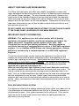
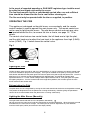
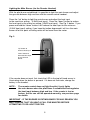
Jazz
&
Jazz “Impact”
DECORATIVE LOG EFFECT ROOM HEATER
User Instructions
These instructions should be read by the user before operating the
appliance and retained for future reference
Model No. FJZL**RN is for use on Natural Gas (G20) at a supply pressure of
20 mbar in G.B. / I.E.
** Denotes trim & colour variant
INSTALLATION INFORMATION
CONDITIONS OF INSTALLATION
It is the law that all gas appliances are installed only by a competent (e.g. GAS
SAFE Registered) Installer, in accordance with the installation instructions and the
Gas Safety (Installation and Use) Regulations 1998 as amended. Failure to install
appliances correctly could lead to prosecution. It is in your own interest and that
of safety to comply with the law.
The fire may be fitted below a combustible shelf provided that the shelf is at least
300mm above the top of the appliance and the depth of the shelf does not exceed
150mm.
The fire may be installed below combustible shelves, which exceed 150mm deep
providing that the clearance above the fire is increased by 15mm for each 25mm
of additional overhang in excess of 150mm.
If this appliance is fitted directly on to a wall without the use of a fireplace or
surround, soft wall coverings such as wallpaper, blown vinyl etc. could be affected
by the heat and may discolour or scorch. This should be considered when
installing or decorating.
The Model number of this appliance is FJZL**RN and it is manufactured by :** denotes trim and colour variant
BFM Europe Ltd.
Trentham Lakes
Stoke-on-Trent
Staffordshire
ST4 4TJ
2
ABOUT YOUR NEW JAZZ ROOM HEATER
The Flavel Jazz decorative fuel effect room heater incorporates a unique and
highly developed fuel bed which gives the realism of a loose log layout combined
with realistic flames and glow. The use of durable hard ceramic material in the
construction of the fuelbed components ensures long and trouble free operation.
When first using the new fire a slight smell may be noticed. This is due to small
deposits of oil on the firebox, but will soon disappear. Please take the time to fully
read these instructions as you will then be able to obtain the most effective and
safe operation of your fire.
DO NOT UNDER ANY CIRCUMSTANCES ATTEMPT TO USE THIS APPLIANCE
IF THE GLASS PANEL IS BROKEN OR HAS BEEN REMOVED.
IMPORTANT SAFETY INFORMATION
WARNING : This appliance has a hot surface and as with all heating
appliances a fireguard should be used for the protection of children, the
elderly and infirm. Fireguards should conform to B.S. 8423 : 2002
(Fireguards for use with gas heating appliances). Servicing should be
carried out annually by a competent person such as a GAS SAFE registered
engineer. It is a condition of BFM Europe Ltd. lifetime guarantees schemes
that this is carried out by a competent person i.e a GAS SAFE registered
Engineer.
The service should include visually checking the appliance, flue terminal and
fireplace for accumulation of debris around the firebox, and inspection of the
ceramic logs, replacing as necessary. Should debris be found upon the fuel-bed,
please contact a GAS SAFE registered installer. The condition of the ceramic log
set should be carefully checked and if necessary the whole unit should be
replaced with a genuine replacement set.
After any servicing work a gas tightness check must always be carried out.
Any debris or deposits should be removed from the log set from time to time. This
may be carried out by referring to the cleaning section as described later in this
book. Only the fuelbed components as supplied must be used and complete and
genuine replacements must be used. Always keep furniture and combustible
materials well clear of the fire and never dry clothing or items either on or near to
the fire. Never use aerosols or flammable cleaning products near to the fire when
it is in use.
SPILLAGE MONITORING SYSTEM
This appliance is fitted with a spillage monitoring system which shuts down the fire
if the evacuation of combustion products from the fire is affected by a partially or
fully blocked flue pipe. If this system operates the fire will go out. If this occurs,
leave the fire for at least three minutes then follow the lighting procedure as
described in the next section.
3
In the event of repeated operation a GAS SAFE registered gas installer must
be called to investigate and rectify the cause.
The fuel bed remains hot for a considerable period after use and sufficient
time should be allowed for the fire to cool before cleaning etc.
The fire must only be operated with the trim as supplied, in position.
OPERATING THE FIRE
This appliance is designed so the pilot burner runs constantly, and the remote
control handset is used to operate the main burner only. The remote control can
not be used to light the pilot burner. The pilot burner control and main gas valve
are located behind the trim, to remove the trim or fascia, see page 12 / 13 for
details.
The control valve features two control knobs, the left hand one to light the pilot,
and the right hand one to adjust the heat input to the appliance from high (5.5kW)
to low (3.0kW). Fig. 1 below shows the control valve.
Fig. 1
Pilot Control
Knob
Main Burner
Knob
Lighting the Pilot
To light the pilot, press the knob in and turn it anticlockwise. (It may be necessary to hold the control knob
in for a few seconds to purge air from the pipe). Once gas is available at the pilot, by turning the control
knob further anticlockwise the piezo igniter will cause a spark at the pilot to light the pilot burner. Once the
pilot burner is lit, hold the control knob depressed for approximately 10 seconds to hold the flame
supervision device in. Let the control knob go and the pilot should remain lit, if the pilot goes out repeat
the lighting sequence. Turn the control knob to the large flame position, this will allow gas to the main
burner section of the control valve.
Extinguishing the Pilot
The pilot flame can be extinguished by turning the left hand control knob clockwise to the position marked
This product is designed to have the pilot burner running continuously, therefore giving full operational
control via the remote handset when the pilot burner is running continuously.
Lighting the Main Burner (Manually)
The right hand control knob will be in the off position, denoted by
No gas can enter the main burner until this control knob is turned anticlockwise. When this knob is turned
anti-clockwise, the main burner will light. The heat input can then be adjusted to any level between
maximum heat input (5.5kW) and minimum heat input (3.0kW).
4
Lighting the Main Burner (via the Remote Handset)
With the pilot burner established it is possible to light the main burner and adjust
the gas rate between high and low with the remote control handset.
Press the “up” button to light the main burner and adjust the heat input
to the maximum setting. (5.5kW heat input). Press the “down” button to reduce
the heat input to the minimum setting (3.0kW heat input). See Fig. 2 below. If you
press and hold the “down” button it will reduce the heat input to the minimum
(3.0kW heat input) setting, if you keep the button depressed it will turn the main
burner off at this point a clicking noise will be heard from the motor.
Fig. 2
“Up” button to
increase heat input
“Down” button to
decrease heat input
or turn off main
burner
If the remote does not work, first check the LED in the top left hand corner is
illuminating when the button is pressed. If it does not illuminate, change the
battery in the handset.
NOTE :
The remote control does not light the pilot, it only lights
the main burner when the pilot flame is established and regulates
the heat input between high and low. If the remote is lost or
broken, the fire can still be operated manually, see previous page
for details.
IMPORTANT : IF THE BURNER IS EXTINGUISHED FOR ANY REASON YOU
MUST ENSURE THAT YOU WAIT A FULL FIVE MINUTES BEFORE
ATTEMPTING TO RE-LIGHT THE FIRE.
5
NOTE : THIS APPLIANCE IS DESIGNED TO WORK SAFELY AND
EFFECTIVELY DURING ADVERSE WEATHER CONDITIONS. HOWEVER,
DURING SUCH TIMES FLAME DISTURBANCE MAY BE NOTICED. THIS IS
NORMAL AND DOES NOT EFFECT OR IMPAIR THE SAFETY OF THE
APPLIANCE.
CLEANING
WARNING : Before attempting any cleaning operation ensure that the fire has
been allowed to fully cool.
CLEANING THE TRIM AND PAINTED METAL PARTS
The extruded aluminimum trim or “Impact” fascia that is supplied for use with this
product must be gently cleaned with a damp cloth only. Abrasive cleaners,
chemical cleaning agents or any type of polish must never be used as
damage to the paint may result.
CLEANING THE FUEL BED
We do not recommend cleaning the fuelbed other than at annual service intervals.
If carbon or soot accumulates on the logs, this should be removed by carefully
brushing the fuelbed using a soft brush. For instructions on how to remove the
glass panel please see page 7. The log set is made from a form of refractory
ceramic fibre and should be handled carefully to avoid generating dust, as
this may be harmful if inhaled. As with some fibrous materials, handling
fibrous materials without gloves could cause skin irritation.
The fuelbed should never be washed or exposed to any cleaning agents or
water.
Any damaged parts must be replaced by contacting your dealer, whose details
may be found on the BFM Europe website, address on the rear page. The log
set must only be replaced with a genuine replacement and the fire must never be
run with a different log set fitted.
The log set must be carefully reassembled as stated in pages 8-11.
6
CLEANING THE GLASS PANEL
To clean the glass panel, first ensure that the fire is cool, please note that the
glass panel will remain hot for a considerable period when the fire has been
switched off.
To remove the glass panel, follow the instructions below for removal and
re-fitting. The glass panel should be cleaned gently with a soft damp cloth and
glass cleaner.
DO NOT UNDER ANY CIRCUMSTANCES ATTEMPT TO CLEAN THE GLASS
PANEL WHEN THE APPLIANCE IS RUNNING.
Fig. 3
Glass Frame Assembly
locates over lip on top
of combustion chamber
lid, and drops onto
flange as shown. To
remove, unclip base
hinge clips as shown in
Fig. 4 and lift clear.
shows correct final
position of glass frame.
Fig. 4
7
REMOVAL & RE-FITTING OF THE FUEL-BED LOGSET
a)
The gravel material should then be first layed around the base of the
combustion chamber as shown below in Fig. 5, leaving the rear
section as shown to allow the fitting of Log “A”
Fig. 5
b)
Place the largest Log “A” centrally onto the fuel-bed support behind the
burner flame strip. Ensure that the fuel-bed Log “A” is located centrally
in the firebox, and that the front edge is parallel with the rear face of the
burner flame strip as shown below in Fig. 6
Fig. 6
A
Fuel-bed
Log “A” to be
fitted behind
burner flame
strip
8
c)
Fig. 7
Fit Log “B” into position on right hand side of the fuel-bed base log
“A”as shown below in Fig. 7, using the groove in Log “B” as a guide for
placement, and locate the in slot the fork of the log into the upturn in the
base plate.
Slot in log to locate
in the base plate
upturn
B
d)
Fig. 8
Fit Log “C” into position on left hand side of the fuel-bed base log “A”as
shown below in Fig. 8, using the groove in Log “A” as a guide for
placement.
Slot in log to locate
in the base plate
upturn
C
9
d)
Fig. 9
Fit Log “D” into position on left hand side of the fuel-bed base log “A”as
shown below in Fig. 9, using the groove in Log “A” as a guide for
placement.
Slot in log to locate
in the base plate
upturn
D
e)
Fit Log “E” into position at centre of the fuel-bed base log “A”as
shown below in Fig. 10, using the groove in the centre of Log “A” as a
guide for placement.
Fig. 10
Slot in log to locate
in the base plate
upturn
E
10
IMPORTANT NOTE
HAVING FITTED THE GRAVEL MATERIAL IN THE BASE OF THE
COMBUSTION CHAMBER, ENSURE THAT NONE OF IT IS ON THE BURNER
FLAME STRIP OR IN THE PILOT ASSEMBLY. IF MATERIAL IS OBSERVED
VISUALLY ON THESE COMPONENTS, REMOVE THE FUEL-BED LOGSET,
REMOVE THE GRAVEL MATERIAL FROM THE BURNER AND OR PILOT AND
RE-FIT THE LOGS AS DETAILED IN ABOVE.
Warning : Use only the logs supplied with the fire. When replacing the
logs remove the old logs and discard them. Fit a complete set of logs of the
correct type. Do not fit additional logs or any logs other than a genuine
replacement set.
This appliance uses fuel effect pieces containing Refractory Ceramic Fibres (R.C.F.), which are
man-made vitreous silicate fibres. Excessive exposure to these materials may cause temporary
irritation to eyes, skin and respiratory tract. Consequently, it makes sense to take care when handling these articles to ensure that the release of dust is kept to a minimum. To ensure that the
release of fibres from these R.C.F. articles is kept to a minimum, during installation & servicing we
recommend that you use a HEPA filtered vacuum to remove any dust and soot accumulated in and
around the fire, before and after working on the fire. When replacing these articles we recommend
that the replaced items are not broken up, but are sealed within a heavy duty polythene bag, clearly labelled as “RCF waste”. This is not classified as “hazardous waste” and may be disposed of at
a tipping site licensed for the disposal of industrial waste. Protective clothing is not required
when handling these arrticles, but we do recommend you follow the normal hygiene rules of not
smoking, eating or drinking in the work area, and always wash your hands before eating or
drinking.
This appliance does not contain any component manufactured from
asbestos or asbestos related products.
11
REMOVAL & RE-FITTING OF THE JAZZ “IMPACT” FASCIA
IMPORTANT NOTE : The trim assembly of this product is
a working surface and as such will become hot in use.
Allow the product and trim to fully cool prior to
attempting to remove it.
a)
The Jazz “Impact” fascia is fitted to the product via hooking the fascia
onto the mounting flange slots at the top and securing via magnets at
the bottom. See Fig. 11 below.
Fig. 11
Hook slots on
trim into slots as
shown below in
Fig. 12
b)
The Jazz “Impact” fascia mounting slots in the combustion chamber,
see Fig. 12 below.
Fig. 12
Slots in lid of combustion chamber for
mounting of the trim assembly
12
REMOVAL & RE-FITTING OF THE JAZZ FASCIA
IMPORTANT NOTE : The trim assembly of this product is
a working surface and as such will become hot in use.
Allow the product and trim to fully cool prior to
attempting to remove it.
a)
The Jazz fascia is fitted to the product via hooking the fascia
onto the mounting flange slots at the top. See Fig. 13 below.
Fig. 13
Hook slots on
trim into slots as
shown below in
Fig. 14
b)
Fig. 14
The Jazz fascia mounting slots in the combustion chamber, see Fig. 14
below.
Slots in lid of combustion chamber for
mounting of the trim assembly
13
USER REPLACEABLE PARTS
The only user replaceable parts on this fire are the fuelbed / log form, as descibed
in pages 8 to 11 and the handset batteries, which may be replaced as described
below. Replacement of any other parts must be carried out by a competent
person such as a GAS SAFE registered gas installer.
The part numbers of the user replaceable parts are as follows, these are available
from specialist spares stockists whose details can be found on our web site,
www.bfm-europe.com, in the ‘stockist’ section.
Log Set (All Models)
B-105650
REPLACING THE BATTERIES IN THE HANDSET
a)
Remove the old 9V battery by removing the cover on the
back of the handset.
b)
Refit new battery and replace cover.
REPLACING THE BATTERIES IN THE ULTRASONIC RECEIVER
a)
Remove the fascia as shown in on page 13. The ultrasonic reciever is
located is fitted to the bottom left hand support leg of the product.
Remove the unit, slide off the cover and replace the 4 off AA batteries.
b)
Refit the unit and the receiver in reverse order.
Due to our policy of continual improvement and development the exact
accuracy of descriptions and illustrations cannot be guaranteed
Part No. B-134950
Issue 1
BFM Europe Ltd.
Trentham Lakes
Stoke-on-Trent
Staffordshire
ST4 4TJ
www.bfm-europe.com
Telephone - General Enquiries :
Telephone - Service :
(01782) 339000
(0844) 7700169