1
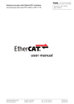
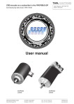
R Series Encoders with CANopen Interface
RNX 11197 HE
11 / 2005
User Manual
TWK-ELEKTRONIK GmbH · PB. 10 50 63 · D-40041 Düsseldorf
· Tel.: +49/211/63 20 67 · Fax: +49/211/63 77 05 · [email protected] · www.twk.de
COPYRIGHT: The RNX 11197 operating instructions
are owned by TWK-ELEKTRONIK GMBH and are
protected by copyright laws and international treaty provisions.
© 2005 by TWK-ELEKTRONIK GMBH
POB 10 50 63 ■ 40041 Düsseldorf ■ Germany
Tel. +49/211 /63 20 67 ■ Fax +49/211 /63 77 05
[email protected] ■ www.twk.de
RNX 11197 HE / Page 2
Table of contents
1. General ................................................................................................................................ 5
2. CANopen features of R Series encoders ......................................................................... 5
3. Installation instructions ..................................................................................................... 5
3.1 Electrical connection ....................................................................................................................5
3.2 Baud rates and lead lengths ........................................................................................................6
3.3 Setting the address and Baud rate ...............................................................................................6
3.4 EDS file ........................................................................................................................................6
4. Process data exchange ..................................................................................................... 7
4.1 Operating modes ..........................................................................................................................7
4.2 Data format...................................................................................................................................8
5. Emergency messages ........................................................................................................ 8
6. Programming and diagnosis (object directory)............................................................... 9
6.1 Overview of the object directory ...................................................................................................9
6.2 Communication parameters .......................................................................................................10
6.2.1 Object 1000h - Device type ......................................................................................................10
6.2.2 Object 1001h - Error register....................................................................................................10
6.2.3 Object 1005h - COB-ID SYNC .................................................................................................10
6.2.4 Object 1008h - Manufacturer device name ..............................................................................10
6.2.5 Object 1009h - Manufacturer hardware version .......................................................................10
6.2.6 Object 100Ah - Manufacturer software version ........................................................................10
6.2.7 Object 1010h - Store parameters ............................................................................................. 11
6.2.8 Object 1011h - Restore default parameters ............................................................................. 11
6.2.9 Object 1014h - COB-ID EMCY................................................................................................. 11
6.2.10 Object 1017h - Producer heartbeat time ................................................................................ 11
6.2.11 Object 1018h - Identity Object ................................................................................................ 11
6.2.12 Object 1800h - First transmit PDO .........................................................................................12
6.2.13 Object 1801h - Second transmit PDO ....................................................................................12
6.2.14 Object 1A00h - First transmit PDO mapping ..........................................................................12
6.2.15 Object 1A01h - Second transmit PDO mapping.....................................................................12
6.3 Standardised device parameters................................................................................................13
6.3.1 Object 6000h - Operating parameters......................................................................................13
6.3.2 Object 6001h - Measuring units per revolution ........................................................................13
6.3.3 Object 6002h - Total measuring range .....................................................................................13
6.3.4 Object 6003h - Preset value.....................................................................................................13
6.3.5 Object 6004h - Position value ..................................................................................................13
6.3.6 Object 6200h - Cyclic timer ......................................................................................................13
6.4 Standardised device diagnosis...................................................................................................14
6.4.1 Object 6500h - Operating status ..............................................................................................14
6.4.2 Object 6501h - Singleturn resolution ........................................................................................14
RNX 11197 HE / Page 3
Table of contents
6.4.3 Object 6502h - Number of distinguishable revolutions.............................................................14
6.4.4 Object 6503h - Alarms..............................................................................................................14
6.4.5 Object 6504h - Supported alarms ............................................................................................14
6.4.6 Object 6506h - Supported Warnings ........................................................................................15
6.4.7 Object 6507h - Profile and software version ............................................................................15
6.4.8 Object 6508h - Operating time .................................................................................................15
6.4.9 Object 6509h - Offset value .....................................................................................................15
6.4.10 Object 650Ah - Modul identification .......................................................................................15
6.4.11 Object 650Bh - Serial number ................................................................................................15
6.5 Manufacturer-specific parameters ..............................................................................................16
6.5.1 Object 2000h - Node ID ...........................................................................................................16
6.5.2 Object 2001h - Bit timing ..........................................................................................................16
7. Examples ........................................................................................................................... 17
7.1 Boot-up .......................................................................................................................................17
7.2 Change parameter .....................................................................................................................17
7.3 Setting the node address via LSS ..............................................................................................18
8. Literature ........................................................................................................................... 19
RNX 11197 HE / Page 4
1. General 2. CANopen features 3. Installation instructions
1. General
The electromagnetic R Series encoders are designed for direct connection to the CAN bus. This is achieved internally
via the CAN bus controller T89C51 CC02 SO 28 (Atmel). The following specifications have been implemented:
Device Profile for Encoders
CiA Draft Standard 406, Version 3.0 /1/
CANopen Application Layer and Communication Profile
CiA Draft Standard 301, Version 4.02 /2/
The CANopen specifications can be obtained from the user organisation CiA (www.can-cia.org).
The following R Series encoders with CANopen interface have been taken into consideration:
Model designation
Data sheet
RNM/RNW
11397
Description
Single-turn encoder
2. CANopen features of R Series encoders
- According to device profile DS 406, version 3.0, Device Profile for Encoders /1/
- NMT slave
- One SDO per communication direction for accessing the object directory
- Two transmit PDOs
- PDO identifier adjustable via SDO
- SYNC message
- EMERGENCY message
- Simple boot-up according to DS 301
- Transmission types can be set for all PDOs
- Node number and Baud rate setting via Layer Setting Service (LSS) /4/
3. Installation instructions
3.1 Electrical connection
CiA Draft Recommendation Proposal 303-1, Version 1.1.1 CANopen Cabling and Connector Pin Assignment /3/ must
be adhered to when connecting the encoder. This particularly applies with regard to the terminal resistors, the lead
characteristics, the length of the branch lines and the transmission length.
The bus terminal resistors must be implemented internally. The precise connector assignment is enclosed with each
device.
Encoder
CAN-Bus
subscriber
Principle bus structure:
CAN_H
CAN_H
CAN-Bus
* 120
CAN_L
120
*
CAN_L
* Terminal resistor
RNX 11197 HE / Page 5
3. Installation instructions
3.2 Baud rates and lead lengths
Baud rate [kBaud]
Lead length [m]
Note:
20
50
2500 1000
125
250
500
800
1000
500
250
100
50
25
(According to CiA DS 301)
The encoder has no galvanic separation between the supply voltage and bus leads; the total bus length is
therefore limited to 200 m.
3.3 Setting the address and Baud rate
The node address (node number) and the Baud rate are set via the LSS - Layer Setting Service (see CiA DS 305).
In this case, each node has a unique LSS address, via which it can be identified in the network. This is comprised of
the following:
Manufacturer ID:
Product number:
Revision number:
Serial number:
0000 010Dh
0000 2000h
0001 0003h
xxxx xxxxh
(TWK manufacturer ID)
(TWK product number)
(current revision number)
(relevant serial number of the sensor)
See example in Chapter 7.3
In addition to the option of setting the node address and Baurate via the LSS, the parameters can also be changed
via objects 2000h and 2001h (see manufacturer-specific object range, Chapter 6.5).
The default values are: Baud rate:
20 kBaud
Node address: 1
3.4 EDS file
The EDS file is enclosed on a diskette in order to integrate the sensor into a project planning tool. This file clearly and
completely describes the characteristics of the CANopen subscriber in a defined format.
After integrating the EDS file into the project planning tool (e.g. CANsetter from Vektor-Informatik), the encoder‘s parameters can be comfortably set and diagnostic information can be read.
RNX 11197 HE / Page 6
4. Process data exchange
4. Process data exchange
In the case of CANopen, I/O data traffic takes place via the PDO (Process Data Object) message. The R-Series encoders provide two PDOs. Their transmission behaviour (transmission type) can be set independently of each other.
4.1 Operating modes
The following operating modes can be set:
Polling Mode (asynchronous-RTR):
The encoder transmits the current, actual position value, after the current position value has been polled via a „Remote Frame“ message by the master.
Asynchronous Mode (cyclic / acyclic):
Without being requested to do so by the master, the encoder transmits the current, actual position value following
a value change and following the expiry of a cyclic time (cyclic timer > 0). The cycle time can be parameterised for
values between 1 ms and 65,535 ms.
Synchronous Mode (synchronous-cyclic):
After receiving a SYNC message transmitted by a master, the encoder transmits the current, actual position value.
The encoder‘s SYNC counter can be parameterised in such a way that the position value is only transmitted following
a defined number of SYNC messages.
Acyclic Mode (synchronous-acyclic):
After receiving a SYNC message, the encoder only transmits the current, actual position value if the position value
has changed since the last transmission.
In the case of CANopen, the operating modes (transmission types) and all other parameters are set via so-called
SDOs (Service Data Object). The transmission types for PDO1 and PDO2 can be found under the indices 1800h and
1801h. (See Chapter 6.2)
The following Table shows the relevant values for the parameters transmission type.
Transmission Type
Code
Transmission type
Cyclic
0
1-240
x
241-251
Reser
252
Acyclic
Synchron
x
x
Asynchronous
RTR
x
x
x
253
x
254
x
x
Meaning
0
1-240
252
253
254
After SYNC, but only if the value has changed since the last SYNC.
Transmit value after 1st or 240th SYNC message.
Cycle Timer = 0
Position integration on SYNC; output of the stored position following
request (Remote Frame).
Cycle Timer ≠ 0
Current position is transmitted in the timer‘s cycle. Position integration
on SYNC; output of the stored position following request (Remote Frame)
remains active.
Cycle Timer = 0
Current position is transmitted upon request (Remote Frame).
Cycle Timer ≠ 0
Current position is transmitted in the timer‘s cycle. Current position
is also transmitted following request (Remote Frame).
Cycle Timer = 0
Data output occurs in the event of a position change. Current position
is also transmitted following request (Remote Frame).
Cycle Timer ≠ 0
Current position is transmitted in the timer‘s cycle. Data output also
occurs in the event of a position change. Current position is also
transmitted following request (Remote Frame).
RNX 11197 HE / Page 7
4. Process data exchange, 5. Emergency messages
4.2 Data format
The definition of the output data (mapping) and their depiction is identical for both PDOs. The position value is output
in steps. The position value can also be called up in the object directory under the index 6004h - Position value. The
position value is depicted in Intel format.
Position value
Byte 0
Byte 1
0 1 2 3 4 5 6 7 8 9 10 11 12 13 14 15
12 Bit Position data
0 0 0 0
5. Emergency messages
Each time the internal error status register (Index 1001h) changes, the encoder transmits an emergency message with
the identifier: 80h + node ID (even if an error which has occurred has been rectified).
An emergency message is comprised of 8 data bytes and is structured as follows:
Byte
Content
0
1
Error code
2
3…7
Error register
(Index 1001h)
Manufacturer-specific
See CANopen Specifications /2/ for error code.
The bits in the error register, index 1001h, (see Chapter 6.1), have the following meaning:
Bit
0
1-6
7
Meaning
General error
Not used
Manufacturer-specific error
In the case of an error, the error register always contains 81h. The cause of the error is then contained in index 6503h.
Bytes 3 and 4 of the emergency message reflect the content of the index 6503h (see Chapter 6.4.4) and may assume the following values:
Bit
Meaning
0-11
Not used
Error rectification
12
EEPROM error
Re-programming an arbitrary parameter
and saving with „save“, index 1010h /01
13
EEPROM CRC error
Re-programming an arbitrary parameter
and saving with „save“, index 1010h /01
14
Not used
15
Sensor error
Encoder voltage supply off/on
RNX 11197 HE / Page 8
6. Programming and diagnosis (object directory)
6. Programming and diagnosis (object directory)
In the case of CANopen, all parameters and diagnostic information are contained in the object directory. There, they
may be changed and/or read with the SDO (Service Data Object) message, specifying their index and sub-index. The
object directory is sub-divided into the following areas:
Communication parameters
Index 1000h - 1FFFh
Manufacturer-specific parameters
Index 2000h - 5FFFh
Standardised device parameters
Index 6000h - 9FFFh
Refer to the following Table for a description of the individual parameters and the diagnostic information.
6.1 Overview of the object directory
Index
Object
Communication Profile Area
1000h
VAR
1001h
VAR
1005h
VAR
1008h
VAR
1009h
VAR
100Ah
VAR
1010h
RECORD
RECORD
1011h
1014h
VAR
1017h
VAR
1018h
RECORD
1800h
1801h
1A00h
1A01h
RECORD
RECORD
RECORD
RECORD
Name
Device type
Error register
COB-ID-SYNC
Manufacturer device name
Manufacturer hardware version
Manufacturer software version
Store parameters
Restore default parameters
COB-ID-EMCY
Producer heartbeat time
Identity object
VAR
6500h
6501h
6502h
6503h
6504h
6506h
6507h
6508h
6509h
650Ah
650Bh
VAR
VAR
VAR
VAR
VAR
VAR
VAR
VAR
VAR
RECORD
VAR
Access
Unsigned32
Unsigned8
Unsigned32
String
String
String
ro
ro
rw
ro
ro
ro
rw
rw
rw
rw
ro
Unsigned32
Unsigned16
1. Transmit PDO
2. Transmit PDO
PDO 1 Mapping
PDO 2 Mapping
Standardised Device Profile Area
6000h
VAR
Operating parameters
6001h
VAR
Measuring units per revolution
6002h
VAR
Total measuring range in measuring units
6003h
VAR
Preset value
6004h
VAR
Position value
6200h
Data type
rw
rw
ro
ro
Unsigned16
Unsigned32
Unsigned32
Unsigned32
Unsigned32
rw
ro
ro
rw
ro
Cyclic timer
Unsigned16
rw
Operating status
Single turn resolution
Number of distinguishable revolutions
Alarms
Supported alarms
Supported warnings
Profile and software version
Operating time
Offset value
Module identification
Serial number
Unsigned16
Unsigned32
Unsigned16
Unsigned16
Unsigned16
Unsigned16
Unsigned32
Unsigned32
Unsigned32
Unsigned32
ro
ro
ro
ro
ro
ro
ro
ro
ro
ro
ro
Unsigned8
Unsigned8
rw
rw
Manufacturer Specific Profile Area
2000h
VAR
Node ID
2001h
VAR
Bit timing
RNX 11197 HE / Page 9
6. Programming and diagnosis (object directory)
6.2 Communication parameters
6.2.1 Object 1000h - Device type
Index
Sub
1000h
00
Name
Data type
Access
Unsigned32
ro
Name
Data type
Access
Error register
Unsigned8
ro
Device type
Range/Value
Default
0x10196
6.2.2 Object 1001h - Error register
Index
Sub
1001h
00
Bit
Meaning
0
General error
1-6
Not used
7
Manufacturer-specific error
Range/Value
Default
The error register is the higher-level error register. Bit 0 and bit 7 are always set in the event of an error (81h ). The cause
of the error is then contained in index 6503h.
6.2.3 Object 1005h - COB-ID SYNC
Index
Sub
1005h
00
Name
COB-ID SYNC
Data type
Access
Range/Value
Default
Unsigned32
rw
0 ... 0x7FF
0x80
Range/Value
Default
Range/Value
Default
Range/Value
Default
Object 1005h defines the COB ID (11-bit identifier) for the Sync message.
6.2.4 Object 1008h - Manufacturer device name
Index
Sub
1008h
00
Name
Manufacturer device name
Data type
Access
String
ro
Contains the manufacturer device name, e.g.: „Encoder RNM“
6.2.5 Object 1009h - Manufacturer hardware version
Index
Sub
1009h
00
Name
Manufacturer hardware version
Data type
Access
String
ro
Contains the manufacturer hardware version e.g.: "P-0453"
6.2.6 Object 100Ah - Manufacturer software version
Index
Sub
100Ah
00
Name
Manufacturer software version
Data type
Access
String
ro
Contains the manufacturer software version, e.g.: „RNM Std“
RNX 11197 HE / Page 10
6. Programming and diagnosis (object directory)
6.2.7 Object 1010h - Store parameters
Index
Sub
Name
Data type
Access
Range/Value
1010h
00
Largest supported subindex
Unsigned8
ro
1
01
Password
Unsigned32
rw
„save“
Default
0
Writing „save“ (in hex: 73 61 76 65) in sub-index 01 saves the current parameters in the encoder‘s EEPROM, where
they are protected against zero-voltage.
6.2.8 Object 1011h - Restore default parameters
Index
Sub
Name
Data type
Access
Range/Value
1011h
00
Largest supported subindex
Unsigned8
ro
1
01
Password
Unsigned32
rw
“load”
Default
0
Writing „load“ (in hex: 6C 6F 61 64) in sub-index 01 loads the parameter‘s default values and saves them in the
encoder‘s EEPROM, where they are protected against zero-voltage.
6.2.9 Object 1014h - COB-ID EMCY
Index
Sub
1014h
00
Name
COB-ID EMCY
Data type
Access
Range/Value
Default
Unsigned32
rw
0 ... 0x7FF
0x80 + Node-ID
Identifier for the emergency message, which the encoder transmits on occurrence of an alarm.
In default status, this has the value 0x80 + node address. If the object is written, the node address is no longer added.
The default status can be restored via „load default“ (object 1011h).
6.2.10 Object 1017h - Producer heartbeat time
Index
Sub
1017h
00
Name
Producer heartbeat time
Data type
Access
Range/Value
Default
Unsigned16
rw
0 ... 65535
0
If the value is > 0, the heartbeat message is transmitted on the identifier guard COB ID + node ID in the heartbeat
time interval in ms.
6.2.11 Object 1018h - Identity Object
Index
Sub
1018h
00
01
Name
Data type
Access
Range/Value
Largest supported subindex
Unsigned8
ro
4
Manufacturer ID
Unsigned32
ro
0x10D
02
Product ID
Unsigned32
ro
0x2000
03
Revision No.
Unsigned32
ro
0x1 0003
04
Serial No.
Unsigned32
ro
0xXXXX XXXX
Default
The information in object 1018h (also see Chapter 3.3) is required to use the Layer Setting Service (LSS, /4/).
RNX 11197 HE / Page 11
6. Programming and diagnosis (object directory)
6.2.12 Object 1800h - First transmit PDO
Index
Sub
Name
Data type
Access
Range/Value
1800h
Default
00
Largest supported subindex
Unsigned8
ro
3
01
COB-ID
Unsigned32
rw
0 ... 0x7FF
0x180 + Node-ID
02
Transmission type
Unsigned8
rw
252,253,254
253
03
Inhibit time
Unsigned16
rw
0 ... 65535
0
Object 1800h defines the first PDO‘s communication data. Only transmission types 252,253,254 are supported.
Sub-index 01
(COB ID) contains the identifier for PDO1.
In default status, this has the value 0x180 + node address. If the object is written, the node address is no longer added. The default status can be restored via „load default“ (object 1011h).
The inhibit time (ms) is the time before the PDO is permitted to be transmitted again.
(See operating modes in Chapter 4.1)
6.2.13 Object 1801h - Second transmit PDO
Index
Sub
Name
Data type
Access
Range/Value
1801h
Default
00
Largest supported subindex
Unsigned8
ro
2
01
COB-ID
Unsigned32
rw
0 ... 0x7FF
0x280 + Node-ID
02
Transmission type
Unsigned8
rw
0 ... 240
1
Object 1801h defines the second PDO‘s communication data. Only transmission types 0... 240 are supported.
Sub-index 01
(COB ID) contains the identifier for PDO2.
In default status, this has the value 0x280 + node address. If the object is written, the node address is no longer added. The default status can be restored via „load default“ (object 1011h).
(See operating modes in Chapter 4.1)
6.2.14 Object 1A00h - First transmit PDO mapping
Index
Sub
Name
Data type
Access
Range/Value
1A00h
00
Largest supported subindex
Unsigned8
ro
1
01
First mapping object
Unsigned32
ro
0x6004 0010
Data type
Access
Range/Value
Default
(see Chapter 4.2)
6.2.15 Object 1A01h - Second transmit PDO mapping
Index
Sub
Name
1A01h
00
Largest supported subindex
Unsigned8
ro
1
01
First mapping object
Unsigned32
ro
0x6004 0010
Default
(see Chapter 4.2)
RNX 11197 HE / Page 12
6. Programming and diagnosis (object directory)
6.3 Standardised device parameters
6.3.1 Object 6000h - Operating parameters
Index
Sub
6000h
00
Name
Operating parameters
Data type
Access
Unsigned16
rw
Range/Value
Default
0
The following Table contains an overview of operating parameters for the encoder. Before scaling the encoder via
object 6003h, the „Scaling function control“ bit must be set to „1“.
Bit
Name
0
Code sense
1
Not used
2
Scaling function control
3 - 15
0
1
CW
CCW
disabled
enabled
Not used
6.3.2 Object 6001h - Measuring units per revolution
Index
Sub
6001h
00
Name
Measuring units per revolution
Data type
Access
Range/Value
Unsigned32
ro
4096
Default
Resolution per revolution in steps.
6.3.3 Object 6002h - Total measuring range
Index
Sub
6002h
00
Name
Total measuring range
Data type
Access
Range/Value
Unsigned32
ro
4096
Default
Data type
Access
Range/Value
Default
Unsigned32
rw
0 … Total
measuring
range -1
0
Total measuring range in steps.
6.3.4 Object 6003h - Preset value
Index
Sub
6003h
00
Name
Preset value
The preset value is displayed as the position value if object 6003h is written and the „Scaling function control“ bit (object 6000h) is enabled. The preset is saved in the EEPROM.
6.3.5 Object 6004h - Position value
Index
Sub
6004h
00
Name
Position value
Data type
Access
Range/Value
Unsigned32
ro
0 ... Total
measuring
range -1
Default
This value is the position value, and is output via the PDOs (see Chapter 4).
6.3.6 Object 6200h - Cyclic timer
Index
Sub
6200h
00
Name
Cyclic timer
Data type
Access
Range/Value
Default
Unsigned16
rw
0 … 65535
0
In the case of values of > 0 ms for the cyclic timer, the position value (or position and speed value) is transmitted
cyclically with PDO 1 (see Chapter 4).
RNX 11197 HE / Page 13
6. Programming and diagnosis (object directory)
6.4 Standardised device diagnosis
6.4.1 Object 6500h - Operating status
Index
Sub
6500h
00
Name
Operating status
Data type
Access
Unsigned16
ro
Range/Value
Default
Default
Object 6500h represents the encoder‘s operating status (also see object 6000h).
6.4.2 Object 6501h - Singleturn resolution
Index
Sub
6501h
00
Name
Singleturn resolution
Data type
Access
Range/Value
Unsigned32
ro
4096 (8192)
Data type
Access
Range/Value
Unsigned16
ro
1
Range/Value
The maximum setable resolution.
6.4.3 Object 6502h - Number of distinguishable revolutions
Index
Sub
6502h
00
Name
Number of distinguishable
revolutions
Default
Number of revolutions befor the output value goes back to zero again.
6.4.4 Object 6503h - Alarms
Index
Sub
Name
Data type
Access
6503h
00
Alarms
Unsigned16
ro
Default
On occurrence of an error, an emergency message is transmitted, and the encoder switches to pre-operational status
(see Chapter 5). The following Table shows the possible errors:
Bit
Meaning
0-11
Not used
Error rectification
12
EEPROM error
Re-programming an arbitrary parameter
and saving with „save“, index 1010h /01
13
EEPROM CRC error
Re-programming an arbitrary parameter
and saving with „save“, index 1010h /01
14
Not used
15
Sensor error
Encoder voltage supply off/on
6.4.5 Object 6504h - Supported alarms
Index
Sub
6504h
00
Name
Supported alarms
Data type
Access
Range/Value
Unsigned16
ro
0xB000
Default
Only the alarms listed under object 6503h are supported.
RNX 11197 HE / Page 14
6. Programming and diagnosis (object directory)
6.4.6 Object 6506h - Supported Warnings
Index
Sub
6506h
00
Name
Supported warnings
Data type
Access
Range/Value
Unsigned16
ro
0
Data type
Access
Range/Value
Unsigned32
ro
Default
No warnings are supported.
6.4.7 Object 6507h - Profile and software version
Index
Sub
6507h
00
Name
Profile and software version
Default
Version of the encoder profile which is implemented and encoder software version. The version numbers are each
BCD-encoded byte-by-byte.
Profile Version
Software Version
Byte 0
Byte 1
Byte 2
Byte 3
Bit 7 - 0
Bit 15 - 8
Bit 7 - 0
Bit 15 - 8
6.4.8 Object 6508h - Operating time
Index
Sub
6508h
00
Name
Data type
Access
Range/Value
Unsigned32
ro
0xFFFF
FFFF
Data type
Access
Range/Value
Default
Unsigned32
ro
Name
Data type
Access
Range/Value
Default
Operating time
Default
Not supported at present.
6.4.9 Object 6509h - Offset value
Index
Sub
6509h
00
Name
Offset value
Internal calculation value.
6.4.10 Object 650Ah - Modul identification
Index
Sub
650Ah
00
Largest supported subindex
Unsigned8
ro
1
01
Offset value
Unsigned32
ro
0
Data type
Access
Range/Value
Unsigned32
ro
Not supported at present.
6.4.11 Object 650Bh - Serial number
Index
Sub
650Bh
00
Name
Serial number
Default
The object contains the device‘s serial number.
RNX 11197 HE / Page 15
6. Programming and diagnosis (object directory)
6.5 Manufacturer-specific parameters
6.5.1 Object 2000h - Node ID
Index
Sub
Name
Data type
Access
Range/Value Default
2000h
00
Node-ID
Unsigned8
rw
1 … 127
1
The sensor‘s node address. After setting the node address via index 2000h, this must be permanently saved in the
EEPROM via index 1010h. It only comes into effect following power off/on or a reset.
This object can also be changed via the Layer Setting Service (see Chapter 3.3).
6.5.2 Object 2001h - Bit timing
Index
Sub
Name
Data type
Access
Range/Value Default
2001h
00
Bit timing
Unsigned8
rw
0…7
7
The sensor‘s Baud rate can be set via this index. After setting the Baud rate via index 2001h, this must be permanently
saved in the EEPROM via index 1010h. It only comes into effect following power off/on or a reset.
This object can also be changed via the Layer Setting Service (see Chapter 3.3).
The Baud rate is set according to the following Table:
Baud rate [kBit/s]
Bit timing value
1000
00h
800
01h
500
02h
250
03h
125
04h
125
05h
50
06h
20
07h
RNX 11197 HE / Page 16
7. Examples
7. Examples
Message traffic between a master and the RNM/RXW encoder during boot-up, when changing a parameter and when
setting the slave address with LSS is shown in the following. The identifier (ID), the transmission direction (Rx/Tx), the
Data Length Code (DLC) and the data bytes are shown in tabular form.
The following applies:
- The encoder has the address 1 (default) and is the only slave
- Encoder with default parameter values
- Tx: Master transmits data to the encoder
- Rx: Encoder transmits data
7.1 Boot-up
The following Table shows encoder boot-up, from switching on the supply voltage to initial transmission of the position
value. The position value is subsequently polled via a Sync command.
Action
Id
Rx/Tx
DLC
Databytes
00
01
02
03
04
Remark
05
06
07
Bus active, encoder in the bus with node address 1
Voltage off -> on
Start all nodes
701
Rx
1
00
Boot up node 1
0
Tx
2
1
0
181
Rx
2
xx
LSB
xx
MSB
Response from
RNM (PDO1)
80
Tx
0
281
Rx
2
xx
LSB
xx
MSB
Response from
RNM (PDO2)
Operational for all
nodes
Master (user) transmits a Sync
Sync from the
master
All values in hex!
7.2 Change parameter
Here the changing of the code sense by the parameter "Operating parameters" Index 6000h is shown. Afterwards the
parameters are saved in the encoders EEPROM.
Action
Write 0x0001
Save parameters
Id
Rx/Tx
DLC
Databytes
Remark
00
01
02
03
04
05
06
07
601
Tx
8
23
00
60
00
01
00
00
00
581
Rx
8
60
00
60
00
00
00
00
00
Response from RNM
601
Tx
8
23
10
10
01
73
61
76
65
"save"
581
Rx
8
60
10
10
01
00
00
00
00
Response from RNM
All values in hex!
RNX 11197 HE / Page 17
7. Examples
7.3 Setting the node address via LSS
In the case of the LSS /4/, either all CANopen subscribers are addressed via a global command or an individual
subscriber is addressed via its LSS address, which is comprised of the manufacturer name, the product name, the
revision number and the serial number (see Chapter 3.3).
In the following example, the sensor is addressed via its LSS address (i.e. is switched from LSS-Operation-Mode to
LSS-Configuration-Mode), node address 2 is programmed and saved. LSS-Operation-Mode is subsequently reset.
The sensor then reboots and logs on (without voltage off/on) with its boot-up protocol. It is now ready to operate with
its new address.
To do this, a switch first has to be made to stop status and the heartbeat timer has to be deactivated, i.e. heartbeat
time=0 (default status).
Attention: During LSS-programming the Heartbeat-Time (Index 1017h) has to be zero (default status).
Aktion
Id
Rx/Tx
DLC
00
01
Stop Node
0
Tx
2
02
00
LSS-Switch Mode
Selective
7E5
Tx
8
40
0D
01
00
00
00
00
00
1. Transmission of the
manufacturer name
LSS-Switch Mode
Selective
7E5
Tx
8
41
00
60
00
00
00
00
00
2. Transmission of the
product number
LSS-Switch Mode
Selective
7E5
Tx
8
42
03
00
01
00
00
00
00
3. Transmission of the
revision number
LSS-Switch Mode
Selective
7E5
Tx
8
43
66
BE
02
00
00
00
00
4. Transmission of the
serial number
(in this case: 179814)
7E4
Rx
8
44
00
00
00
00
00
00
00
Success message from the
sensor, which is now in LSS
Configuration-Mode
7E5
Tx
8
11
02
00
00
00
00
00
00
Node address 2
programming
7E4
Rx
8
11
00
00
00
00
00
00
00
Success message from
the sensor
7E5
Tx
8
17
00
00
00
00
00
00
00
Zero-voltage-protected
saving
7E4
Rx
8
17
00
00
00
00
00
00
00
Success message from
the sensor
7E5
Tx
8
04
00
00
00
00
00
00
00
Sensor is reset to
LSS-Operation-Mode
702
Rx
1
00
LSS-Configure
Modul ID
LSS-Store Configuration
LSS-Switch Mode
Global: Operation
Mode
Databytes
Comment
02
03
04
05
06
07
Stop node for all
nodes
Boot-up node with new
node address
All values in hex!
RNX 11197 HE / Page 18
8. Literature
8. Literature
/1/
CiA Draft Standard 406, Version 3.0, Device Profile for Encoders
/2/
CiA Draft Standard 301, Version 4.02, CANopen Application Layer and Communication Profile
/3/
CiA Draft Recommendation Proposal 303-1, Version 1.1.1 CANopen Cabling and Connector
Pin Assignment
/4/
CiA Draft Standard Proposal 305, Version 1.1.1, CANopen Layer Setting Services and Protocol (LSS)
RNX 11197 HE / Page 19