1
Waves - Linear Phase EQ
Software Audio Processor
Users Guide
th
Version 1.1 December 20 2001.
Waves LinEQ software guide page 1 of 15
Chapter 1 – Introduction
Introducing Waves – Linear Phase Equalizer. The LinEQ is designed for ultra
precise equalization with 0 phase shifting. This tool offers a handful of features to
answer to the most demanding, critical equalization needs.
The main broadband component offers 6 bands, 5 general bands and 1 special
Low Frequency band.
For more surgical Low frequency manipulation we created the 3-band low
frequency component.
LinEQ offers +/- 30dB per band of gain manipulation range, and a special
selection of filter designs for maximum flexibility and a wide choice of “sound”
preferences.
The LinEQ works in real time and is controlled with the Paragraphic EQ interface
In legacy of Waves Q10 and Renaissance EQ.
WHAT IS LINEAR PHASE EQ ?
When we use Equalizers we like to think that they are changing the gain of a
selected "band" leaving everything else untouched. The truth is that any normal
analog or digital EQ processor introduces a different amount of Delay or Phase
shift for different frequencies. The levels of all frequencies are linear, but the
phase is not.
The audible effect of this phase distortion is arguable. A trained ear may classify
and justify its effect as good sounding "coloration". The first elements to suffer
are short transients, which have a lot of frequencies happening simultaneously
for a short, Localized period of time. In this case phase distortion simply
degrades sharpness and clarity and somewhat smears the transients over a
longer time.
The digital domain offers us a method to achieve accurate Equalization without
any phase distortion. The - Linear Phase EQ method is based on Finite Impulse
Response filters. It presents no quantization error and is 24bit clean when idle. In
normal EQ different frequencies get different delay or phase shift. In Linear
Phase EQ all frequencies are delayed by the exact same amount, which is at
least half the length of the lowest frequency you are dealing with. It is much more
memory and calculation intensive then any normal digital EQ but is purer or truer
to the source as it doesn’t alter phase relations.
WHY - LINEAR PHASE EQ ?
Linear phase equalization is not widely offered for its intense calculation
requirements. The lower the frequency the more intense the calculation and
longer delay is required too. Waves engineers found ways to make this
technology available as a real time process in most DAW environments. This
Waves LinEQ software guide page 2 of 15
breakthrough technology required some sophisticated math magic in order to
meet the demands of the highest end sound engineers. It is primarily intended for
use in Mastering though it is very possible to use for other audio processing
needs as far as your process power will allow.
As usual, the main reason to use LinEQ would be for its sound. Whether it’s your
first experience with Linear Phase Equalization or if you are already familiar with
it, take the time to explore the sound of the LinEQ. As typically most users are so
much accustomed to the sound of normal EQ’s and their phase shift coloration,
this EQ is going to sound different. The sound of Linear Phase Equalization has
been described to be more transparent, more preserving of the musical balance
while still very effectively manipulating the harmonic spectrum.
The LinEQ provides a wide selection of filter types. There are 9 filter types
offering 2 types of Shelf and Cut filters. One type is the resonant “Analog
modeled” filters using the Q control for more or less overshoot. The other type is
the precision filter offering slope or dB per Octave response using the same Q
control. The bell filters are not symmetrical when boosting or cutting and have
been designed for the best “sweetest sounding” results per our latest
psychoacustic research.
The basic operation of LinEQ is as easy as that of any other EQ with some
special “Advanced” options to help you reach the best results in the most
demanding, delicate and critical of situations. This users guide is here to detail
every aspect of operating the LinEQ. It is recommended to read the guide
through in order to understand how to make the most of it. That being said it is
mostly recommended to read Chapter 2 - Basic Operation through. After reading
this chapter it is quite probable that you would feel right at home and get great
results even if you choose to trust your intuition.
Waves LinEQ software guide page 3 of 15
Chapter 2 – Basic Operation.
LINEQ – PLUG-IN COMPONENTS
The LinEQ plug-in consists of two components available in mono or stereo.
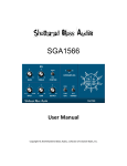
LinEQ Broadband:
This is the main broadband component offering 6 Linear Phase EQ bands.
Band 0 or LF is the Low Frequency Band and it offers a range from 22Hz to 1kHz
with 1 Hz resolution for precise low frequency cutoffs.
The other 5 bands work in frequencies 258Hz – 18kHz. The resolution is 87Hz
and intended mostly for the higher frequencies.
The Low Frequency band is different from the other 5 and does not have the
same behavior and range of features. The 5 main bands have smooth real-time
performance and you can hear the changes while you drag. The Low Frequency
band has to be re-set for every change in cutoff or gain so you will hear the new
setting only when you release the mouse. The Low Frequency band is also has a
smaller Q range and doesn’t offer resonant shelf or cut filters.
Waves LinEQ software guide page 4 of 15
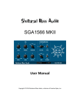
LinEQ Lowband:
This is the Low Band component offering 3 Linear Phase EQ bands dedicated for
low frequency manipulation.
The 3 bands work from 11Hz to 602Hz with a resolution of 11Hz.
All bands in this component offer all nine filter types with similar features to the 5
main bands of the main broadband component. These bands are similar to the
Low Frequency band of the main broadband component in that they need to be
reset for every change so you will hear the new setting only when you release
the mouse and not while dragging.
LATENCY – DELAY IN WAVES LINEAR PHASE EQ
As noted the Linear Phase EQ makes constant delay for all the audio rather then
different delay to different frequencies. This constant delay varies between PlugIn components and is as listed here:
44kHz LinEQ Broadband = 2679 samples = 60.7 ms.
LinEQ Lowband = 2047 samples = 46.4 ms.
48kHz LinEQ Broadband = 2679 samples = 55.8 ms.
LinEQ Lowband = 2047 samples = 42.6 ms.
88kHz
LinEQ Broadband = 5360 samples = 60.9 ms.
LinEQ Lowband = 4095 samples = 46.5 ms.
96kHz
LinEQ Broadband = 5360 samples = 55.8 ms.
LinEQ Lowband = 4095 samples = 42.6 ms.
Waves LinEQ software guide page 5 of 15
QUICK START
Please refer to the WaveSystem Manual for a full explanation regarding standard
Waves controls.
1. The LinEQ opens idle of active processing and all bands are off. Band 1 type
is set to Low-cut (Hi-pass). The 4 main bands are set to the Bell type. The 6th
“Hi band” is set to the Resonant Hi Shelf type.
2. Preview the source track or play audio depending on your platform.
3. Click and drag any band marker in the graph to change the Gain and Freq. of
that band. The default settings are designed to be usable immediately for a
wide range of applications.
4. Double-click any band marker to turn it on or off, or just drag it to turn it on.
5. Option-drag any band’s marker to adjust the Q (left/right movement)[PC uses
Alt-drag]. Vertical movement always changes the gain.
6. Command-click any band marker to change the filter type. It will toggle to the
next type available for that band (not all bands have all filter types). [Not
supported in Windows].
7. Control-drag any band marker to constrain that band to move in one direction
and adjust either gain or frequency.
Waves LinEQ software guide page 6 of 15
Chapter 3 – Filters, Modes and Methods.
The LinEQ linear Phase Equalizer has 3 filter implementations.
1) The 5 main-band filters of the main broadband component.
2) The low frequency filter of the main broadband component.
3) The 3 Low Frequency filters of the Low frequency component.
LINEQ-BROADBAND, BAND 0 OR LF
The Low frequency band of the broadband component has only 5 Filter Types –
Low Cut (Hi Pass), Low Shelf, Bell, Hi Shelf and Hi Cut (Low Pass).
The Q factor of this band will effect the width of the bell filter, or the slope of the
Cut or Shelf filter. The highest value will be the strongest slope. The Method that
is selected in the Method selector control will not effect this band’s response. It
has its own method that gives it its proud round, fat sound. As this band is reset
with every change of parameters, the sound will not change while dragging the
band marker but only when releasing the mouse will the filter be set and heard.
The recommendation is to set the general filter using the graph marker and then
fine tune by moving the Freq. and Gain values with the arrow keys. You should
anticipate the little clicks whenever the filter is re-set.
LINEQ-BROADBAND, BANDS 1 – 5
The main-band filters of the broadband component all have 9 Filter Types or
actually all Shelf and Cut filters have 2 flavors.
One is Variable Slope Precision Filter that uses the Q control to specify the slope
of the filter. The other flavor is the Resonant Analog Modeled Filter, which uses
the Q control to specify how much overshoot resonance will be at the top of the
filter slope. The filters are subject to a choice of 3 different Design
Implementation Methods. Read on in this chapter for more info on the DIMs.
Wide bells at the lower possible frequencies may have some shelving effect and
the gain at the ends of the range may be above unity. What you see is what you
get.
LINEQ-LOWBAND, BANDS A, B, C.
The Low Frequency component has the same 9 Filter Types as the main-band
filters of the broadband component. They behave in the same manner too and
follow the same DIMs. The Low Frequency component filters cutoff’s work in the
range of 11Hz – 600Hz. Achieving Linear Phase Equalization for Low
frequencies requires more memory and process power. This component has an
optimized FIR for low frequency manipulation. Extreme settings will cause some
ripple phenomenon, which are little fluctuations in frequency response. The filter
graph view will not conceal it and you will be called to make the decision as you
please. As in the low frequency band of the broadband component, when
dragging the band’s marker, the sound will only be reset when releasing it and
the result will be heard when set.
Waves LinEQ software guide page 7 of 15
DESIGN IMPLEMENTATION METHOD
The LinEQ allows you to design your filter by specifying the Frequency, Gain and
Q properties of the desired filter. These properties feed our FIRE - Finite Impulse
Response Engine’s variables and are translated to process coefficients.
All the filters in LinEQ, except LinearEQ-main Band 1, are subject to three design
implementation methods. The “Method” control box shows the currently selected
method.
When working with moderate settings i.e. boosting or cutting less then 12dB at
average Q values, the effect of the Methods is minimal and the Normal method is
recommended. When the task at hand calls for more extreme settings, the
Method selection becomes a tool to answer to some of the tradeoffs. The major
tradeoff is between steepness of cutoff slopes and the floor of the stop-band
ripple ('ripple' being small fluctuations in frequency response). The "accurate"
mode will also produce somewhat higher pass-band ripple.
Read on to know more about different “Methods” and their applied behavior.
The methods LinEQ offers are named Normal, Accurate and Low Ripple and
each presents a different implementation for the specified filter properties. The
essential difference between the methods is between accuracy of the
implemented filter and its stop-band. In example lets look at the task of cutting a
narrow notch.
Lets say we are cutting 30dB at a narrow Q of 6.50 at 4kHz cutoff frequency.
Toggling between the 3 Methods will show that only in the Accurate method will
the notch filter reach –30dB at the Cutoff frequency. In the normal method the
implemented filter will only cut about –22dB and in the Low Ripple method only
–18dB. This stresses that for the task of cutting narrow notches the accurate
Method reaches the best results. So what are the Normal and Low Ripple
Methods good for?
Lets now look at the task of creating a Hi-Cut (Low-Pass) filter. When we design
a Hi-Cut filter, the Method specified will determine the accuracy of the slope vs.
the gain in which the slope stops its accurate descent and a further descending
ripple begins. This point is also known as the stop-band. Lets create a Hi-Cut at
4kHz. The Q control will specify the desired slope with Q-6.50 being the steepest
slope possible. Now as we toggle between Methods you will see that the
Accurate Method gives a near brickwall drop at the cutoff frequency but the
accurate descent will stop at about –60dB and from there upwards in the
frequency domain, a slowly descending ripple will occur. The Normal Method will
yield a more moderate slope or a lower dB per Octave value. The stop-band will
occur in a higher frequency but at a lower gain of about –80dB. This same
difference will be even more extreme using the Low-Ripple Method. The slope
will be even more moderate and the stop band will happen at a higher frequency
but at a lower gain of under -100dB.
Waves LinEQ software guide page 8 of 15
As the stop band occurs in low gain values it can not be seen in the LinEQ
Graph’s +/-30dB resolution. It can be viewed with a spectral analyzer that has
higher resolution. Sound wise, the higher the stop band the more audible the
ripple’s coloration will be. The target is to reach the best sounding result, which
may be different between users. Some may regard the –60dB floor as negligible
or as a fair compromise for the steep slope. Sometimes selecting a less accurate
Method and adjusting the cutoff to compensate for the slopes moderated descent
is the way to go.
What about Peaking EQ bells and boost or cut shelves? The accuracy of the
slope is less of a tradeoff here. Still extreme boost and cut settings may create
some Side-Lobes to the specified designed filter. These will be higher in the
Accurate Method and lowest in Low-Ripple Method. Bells in the lower and
highest frequencies may have a slight shelving effect, so the gain at the end of
the scale may be above unity. What you see is what you get and again the
methods will have an effect on this.
Waves LinEQ software guide page 9 of 15
Chapter 4 – Controls and Displays.
CONTROLS
LinEQ Band Strips
Each band in the LinEQ has a band strip with 5 controls that define the settings
of that band.
GAIN.
-30dB - +30dB. Default 0dB.
The Gain value specifies by how much its band is to be boosted or cut.
FREQ.
LowBand: 10 – 600Hz. BroadBand LF: 21-1000Hz. BroadBand 1 – 5: 258 –
21963Hz.
Specifies the band’s Cutoff frequency. For bells this is the center frequency. For
shelves it would be the frequency in the middle of the slope.
Q.
Specifies the band’s bandwidth. The exact statistics vary between the different
filters types.
Broadband LF Band: 0.60 – 2. Broadband Bands 1 – 5: 0.26 – 6.5.
LowBand All Bands – 0.26 – 6.5. For Resonant Analog Modeled filters The
highest Q is 2.25.
• For Bells it specifies how wide or narrow the filter will be.
• For the Variable Slope Shelves and Cut/Pass filters this value defines the
steepness of the slope.
• For Resonant Shelves or Cut/Pass filters this defines how sharp and strong
the resonance overshoot will be. In extreme settings the overshoot spikes
both high and low with a narrow 12dB notch.
Waves LinEQ software guide page 10 of 15
TYPE.
This control has a pop-up menu that lets you select one of the available filter
types. And it toggles the selection when hit on the filter shape display.
ON/OFF.
Turns a certain band on and off. Bands will turn on automatically when their
graph marker is selected and dragged. Toggling low bands may slightly “pop”.
The Global Section
While the controls in each band strip apply to just one band. The controls in the
Global section apply to the Linear Phase EQ as a whole.
GAIN FADER.
The gain fader lets you reduce the Signal’s gain. When you apply strong peaking
EQ, overriding the full digital scale will cause distortion. If your signal is hot and
you want to boost some of it further, the gain fader lets you get more
manipulation headroom. Using the auto Trim control can also set this gain value
for accurate compensation of over full scale values.
TRIM.
Waves LinEQ software guide page 11 of 15
This control shows the margin between the program’s peak and the full digital
scale in dB. Clicking on the trim control automatically trims the specified margin
by applying the specified value to the Gain control. Trimming upwards is limited
to +12dB. Trimming downward is the most important application for eliminating
clipping. It is most recommended to use Trim when you see the clip lights are lit.
The current value in the trim window will be applied to the Gain fader. There is
little point to use the trim many times throughout the program as you would do
better with a steady gain for the whole passage. The recommended practice is to
let the whole passage go through or just the loudest bit, and then trim. Repeat
this until the program passes through and no clipping is indicated and the Trim
window shows 0.0. If you do wish to “ride” the gain, it’s better done in smooth
tweaks rather then sudden jumps in gain so be aware if you are automating.
METHOD.
Normal, Accurate, LowRipple. Default – Normal.
This control selects the desired Design Implementation Method between Normal,
Accurate and Low-Ripple. See - Design Implementation Methods in Chapter 3.
DITHER.
On, Off. Default – On.
As the LinEQ process is a double precision 48bit process, the output is rounded
back to 24bits. While the equalization doesn’t present quantization error and
noise, the rounding back to the 24th bit may. It is On by default, but it is the
choice of the engineer weather to add low level hiss like noise or to get slight low
level nonlinear distortion from quantization noise. Either noise types will be
extremely low and rather inaudible.
SCALE.
12dB or 30dB.
Selects View scale for the Graph. When working on delicate EQ a 12dB view
may be more comfortable bands with gain settings stronger then +-12dB will slide
out of view, but is still controllable from the band strip controls and by toggling the
graph view scale at any time.
DISPLAYS
Waves LinEQ software guide page 12 of 15
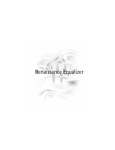
THE EQ GRAPH
The EQ graph shows a view of the current EQ settings. It shows Frequency at
the X axis, and Amplitude t the Y axis. It also provides a visual work surface.
Setting EQ parameters directly on the graph is possible by click dragging each of
the 6 band’s grab markers. Alt-Drag would change the Q for the selected band
and Ctrl-Click would toggle the Type. The graph has 2 possible amplitude scales
showing either +/-30dB or +/-12dB.
OUTPUT METERS AND CLIP LIGHTS
The Output meters and clip lights show the output energy in the Left and Right
channels in dB from 0dB down to –30dB. The clip lights light up together when
any output clipping occurs.
A peak hold indicator under the meters shows the peak value until reset by
clicking on it.
Waves LinEQ software guide page 13 of 15
Chapter 5 - Factory Presets
The presets supplied with the LinEQ are intended to provide some starting point
settings, which the user will need to tweak as needed. Some of the presets set
bands to “Classic” frequency positions in the legacy of the late Peter Baxandall
who designed “tone” circuits to boost or cut Bass and Treble using wide Q bandpass circuits. The legendary Michael Gerzon contributed Shelving EQ choices
alternative to Baxandall, these are represented in the LinEQ’s presets. The
LinEQ does not emulate the sound of the original Baxandall Circuit, but they set
the general center Frequency and Q for the low and high band typical to
Baxandall’s circuits. The actual EQ preset is flat and you can start boosting or
cutting. When comparing to the REQ you may find some differences in the
selected Cutoff frequency for Gerzon shelves, this is due to the different
definition of the shelf cutoff between REQ and LinEQ and are selected to provide
a similar spectral manipulation of the overall frequency response.
Some more presets are set to clean DC offset and LF Rumble without phase
distortion. The “Resonant and Narrow” Presets showcase how you can use
Precision Variable slope cut filters and Resonant Analog Modeled filters together
to get both extra steep slope and Resonance overshoot at the same time.
LINEQ BROADBAND PRESETS
Full Reset –
The settings are the LinEQ Defaults
All bands are Bells, accept the highest band that is a Resonant Analog modeled
Hi-Shelf, all bands are ON. Band Frequencies are set to cover much of the
wideband focusing on low-mid to high frequencies and Q’s are fairly wide with
Mastering in mind.
LF or Band 0 – Freq:96, Q:1.2
Band 1 – Freq.: 258, Q: 1.
Band 2 – Freq.: 689, Q: 1.
Band 3 – Freq.: 1808, Q: 1.
Band 4 – Freq.: 4478, Q: 1.
Band 5 – Freq.: 11025, Q: 0.90, Type: Resonant Analog modeled Hi-Shelf.
Baxandall, Low-Mid, Warm, Presence, Hi –
All Bands are bells. LF and Band 5 are set to Baxandall Bass, Treble. The 4
bands between are set to Low-Mid, Warm, Presence and Hi.
LF or Band 0 – Freq:60, Q:1.2 – Baxandall Bass.
Band 1 – Freq.: 258, Q: 1. – Low-Mid Bell.
Band 2 – Freq.: 689, Q: 1. – Warm Bell.
Band 3 – Freq.: 3273, Q: 1. – Presence Bell.
Band 4 – Freq.: 4478, Q: 1. – Hi Bell.
Band 5 – Freq.: 11972, Q: 0.90. Baxandall Treble.
Gerzon Shelves, 4 Medium bells –
Waves LinEQ software guide page 14 of 15
Another full mix setup, Bands are more evenly spread and have a Higher,
narrower Q.
LF or Band 0 – Freq:80, Q:1.4 Type – Low Shelf. Gerzon Low-shelf.
Band 1 – Freq.: 258, Q: 1.3.
Band 2 – Freq.: 689, Q: 1.3.
Band 3 – Freq.: 1808, Q: 1.3.
Band 4 – Freq.: 4478, Q: 1.3.
Band 5 – Freq.: 9043, Q:0.90, Type: Resonant Analog modeled Hi-Shelf. Gerzon
Shelf.
Baxandall, 4 bells “MIX” Setup –
All bands are Bells. Baxandall Bass, Treble again. The 4 bells are more evenly
distributed.
LF or Band 0 – Freq:60, Q:1.2 – Baxandall Bass.
Band 1 – Freq.: 430, Q: 1. – Low-Mid Bell.
Band 2 – Freq.: 1033, Q: 1. –Mid Bell.
Band 3 – Freq.: 2411, Q: 1. – Presence Bell.
Band 4 – Freq.: 5512, Q: 1. – Hi Bell.
Band 5 – Freq.: 11972, Q: 0.90. Baxandall Treble.
Resonant and Narrow –
This preset uses a Precision Variable Slope High-cut and a Resonant Analog
modeled Hi-Cut to showcase a powerful, steep combined cut filter.
Try clicking Bands 5 and 6 off and on to see how the analog provides the
overshoot and the Precision variable slope provides the near Brickwall
steepness. The overshoot is a hysterical 12dB, and you can use Band 6’s Q to
moderate it. The Slope is as steep as possible about 68dB/Oct and you can use
band 5’s Q to moderate it.
Band 4 – Freq.: 7751, Q: 6.50, Type: Precision Variable Slope Hi-Cut.
Band 5 – Freq.: 7751, Q: 5.86, Type: Resonant Analog Modeled Hi-Cut.
This setup is intended as an example of combining the virtues of both filter cut
types rather then a starting point.
LINEQ LOWBAND PRESETS
Full Reset These are the LinEQ LowBand default settings. Band-A or the lowest band is set
to a Precision Variable Slope low-cut and is off by default for flat response. BandC is a Precision Variable Slope high Shelf, but it depends how you look at it. If
used in conjunction with the broadband component the high shelf can work in a
reversed overall effect, actually providing a lower plateau for the LowBand
Component in relation to the Broadband.
Band A – Freq.: 32, Q: 0.90, Type: Precision Variable Slope low-cut.
Band B – Freq.: 139, Q: 0.90, Type: Bell.
Band C – Freq.: 600, Q: 2, Type: Precision Variable Slope high Shelf.
Waves LinEQ software guide page 15 of 15
Baxandall, Low, Low-Mid setup –
All bands are Bells, all bands are ON. This setup provides a Baxandall Bass filter
and a Low bell and Low-Mid Bell for good surgical operations in the Land of Low
Frequency response.
Band A – Freq.: 64, Q: 0.5. Baxandall Bass.
Band B – Freq.: 204, Q: 1. Low Bell.
Band C – Freq.: 452, Q: 1. Low-Mid Bell.
Gerzon Shelf, 2 LF Medium Bells –
Band A is a Gerzon Low-Shelf. Bands B,C are Low, medium wide Bells.
Band A – Freq.: 96, Q: 1.25. Gerzon Shelf.
Band B – Freq.: 118, Q: 1.30. Low Bell.
Band C – Freq.: 204, Q: 1.30. Low Bell.
DC-Offset Removal –
This preset is actually a tool of choice for a first run to purify the source from a
Constant energy shift to one side of the 0. Since DC offset is cumulative, it may
make it all the way from a single track to the mix. Slight DC offset actually
denominates your dynamic range and poses a challenge in the Analog domain
leading to less then optimal reinforcement. This preset will not introduce any
artifacts, but it will simply eliminate any DC offset or sub frequency >20dB
underflows providing a better starting point for the mastering process.
Band A – Freq.:21, Q:6.5, Type: Precision Variable Slope Low-cut.
Remove DC, Lower Rumble –
Another tool to eliminate DC offset and also lower Low Frequency Rumble
introduced by mechanical components such as Microphone or Turntable.
Band A – Freq.: 21, Q: 6.5, Type: Precision Variable Slope Low-cut.
Band B – Freq.: 53, Q: 3.83, Gain: -8, Type: Precision Variable Slope Low-Shelf.
Resonant and Narrow –
This preset uses a Precision Variable Slope Low-cut and a Resonant Analog
modeled Low-cut to showcase a powerful, steep combined cut filter.
Try clicking Bands A and B off and on to see how the analog provides the
overshoot and the Precision variable slope provides the near Brickwall
steepness. The overshoot is at 3dB, and you can use Band B’s Q to moderate it.
The Slope is as steep as possible about 68dB/Oct and you can use band A’s Q
to moderate it.
Band A – Freq.: 75, Q: 6.50, Type: Precision Variable Slope Hi-Cut.
Band B – Freq.: 75, Q: 1.40, Type: Resonant Analog Modeled Hi-Cut.
This setup is intended as an example of combining the virtues of both filter cut
types rather then a starting point.
Waves LinEQ software guide page 16 of 15