1
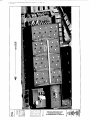
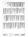
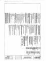
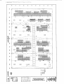
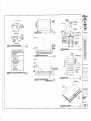
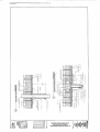
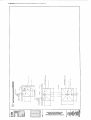
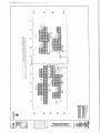
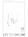
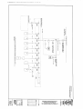
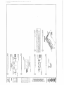
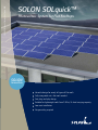
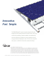
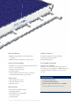
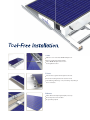
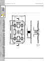
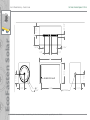
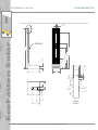
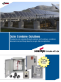
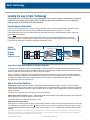
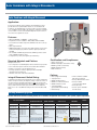
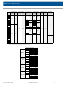
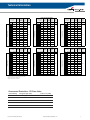
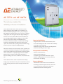
Attachment C
ITSF13000704/CD
Muni Ways & Structures Facility
100kW Solar Electric Project
Muni Maintenance Facility: Building A
700 Pennsylvania Avenue, San Francisco, CA
I.
Attached Documents
A. Construction Drawings
B. PV Modules & Racking (SOLON Solquick)
C. Eco Fastener Info
D. Combiner/Recombiner Cut Sheet
E. Inverter Cut Sheet
ITSF13000624/CD
Page 1 of 1
•dEEGftBwi.uc-
MUNI WAYS & S T R U C T U R E S FACILITY
PHOTOVOLTAIC (PV) P R O J E C T
700 PENNSYLVANIA AVENUE, SAN FRANCISCO, CA 94114
1
i
S I Q CXJFOMl tUETKCJi. CCCC ff«T I OTIE 14. CC4)
fflio
C U I H motHtcit
4. joto u n M
C U E (cue) (win 4. ran » . a n )
P l u m e tax
1 s u a u u m w litSKt
e.
| i u n | i flwr i . i m i i t . a n ]
(ere) (pun i. ITTLE 34, K»)
CODE (FOR t. HEU i t . ecu)
DRAWING INDEX
SCOPE OF WORK
m o a n ra HIIHI « 100 m F w n w a n e (fi) STSTEU. » ™ m m w u UENUC 11 I I i n H I S
H I smucrmtj FIOUTY. 111 PI U M B « I a m i * s u r a UMTJ m e n * u s PCHIMII
I I K K D WKtOBFO) m 1HF. HUH MIMG K » . B C U W BUMMS B X T H I M maMBID MIH 1 NEW
VBB8H& BOCf mat ID rv Kruiwcti
ID.1
EUEIMW. nirpur RE) n i BE RGWID HI toNDmrs 10 w unianrji ITO Q S M J H x u r n s ID IC FOHH)
TO BC IUIITD t> Root 1114. THE OUTPUT IC PCWI W t BF FED TQ Iht F4CUTD W K Q f C I U K
w i o a o m n • KXM «ns W I I K S I E ELECTROICOMFEIEK
BIHUETURAi.
MUNI WAYS S STRUCTURES FACILITY
PHOTOVOLTAIC (PV) PROJECT
700 Pennsylvania Avenue, San Frantisco, CA
APPLICABLE CODES AND STANDARDS
I. mi a c u t M i k u K n c ( m l a m
GENERAL
TDJ
THE S H I
are pun
EE)
S K K U . W M S H O SftOFCUimi
s p E o r a n M «*o usnowtjins
Sl.l 1CQF nj/t
11,1 r i u u
ZOID C J U F H M f n r o f f (CFC) (wrr a. m u i t . PJWT BJ
sum n s i a o i i c n s a u / n » S B B M : OFFICE o» i w n o t FUE IKHS™. C U E n
11.10a
a. I H * * H - I I - I u v a n o i o n c u w u o I W U H . sraitus Ran™ u s MTHOHL « a « * m RDEGJ ( s i - a - i o i i
>. A s a i-ns y n u crsca u w s m B u u x a urn OWE* E M i u B
*BC»riECTUR*L
41.1 rvcr n v i M Exm KCI
W1 U H FUSHMl O K U
.
H U I D f f U M C EC7IU
HU
i r a ffnUTKn E u v CQnfraA4rb*4
ELECTRIC*!
fai
s n e c o . EDUWL x n u . UBIIFIUIIM
EFU
Et.l
•.1
eu
SPED/CAIAS
IDCF PuU
PHtTW. SmU) WftHG PLUi
rwnw. s m i a M M G PLM
QJ
a.t
™ m * STOKC « K 1 F U *
IWTM. raw « a c FUN
as
Ell
niznctL HOI FUH
SHO£ I H D M U U
D.1 a n n o BIS (NXUtTDQ t RSEH
n.i
atom
DEUU
UtUfMt
VICINITY MAP
MOJECTLOCurum
S/l/ll
«
PROJECT TEAM
.
^
n* nunasai m i m , POUTS *
ran
somas D F I W W I tumsco R I B E H U B
•CNEWaE ENQ3CT CEhEPUTm
csyuaun
i
para ENiE» m&
•f
\
t
0
1
;...
3U B U I N U1E
70i n a m
ICR UICWU. f t LELO H>
« K E « B £ (KFJCT O J B O T S U PHONE: (<t3) U 4 - U U
nHDtuu m a
1
1
! LM
11! j
GEWutiM n «
(111) I M - S I K
uiw'mis'ffiiinuCTjsES l u i m o o c E »CUTY
5
JO0 KHNSfUWIM « t " j e
SMI ISHSCCO. u n u t
cwrjcn
m i MWHS. K H . n m t [tisi S K - I I H
M i l MWMlBlk
HIUWD M i l HUH. PKOkt [IIS) IDt>tU)
r
1
.
1
•
J
1 • -
1> XX
.
J/J1/10I)
STOP, UC
s o n atrunvt PMUWIT. CUTE
HK
wot M
tn
tun
"
UFM-1JXK
414 IHQCV mCT OBTE U S
H
,
l
r
S M m w e s c a CA 94103
)J TECimCAV IKSF
*
i
1 '~° \
•
\
i
S3
INC P R )
I H IQ»«TX1 f3KJT. HllEI 4
.
UMI
amccm. a S4S2D
n a i E t i untune K M HUD, PE
ti-
FIX-, u i - n t - a i n
ElECTKJ". Die t o n . tu Km. PE
TITLE SHEET
PHOBE 12S-I7T-5JM
F U fZ ! ^ » - D 1 d
SfimCIUWL I K M H l ! kUCT TEWEBUU, PE (tut)
pnOflt 4I3-775-1BI
FU; 4U-J7I-WU
•" s
.
f
1
•
i
-
1:
nary H i D C K E I I PHIJP D. o a o s n , PE. RBC (ns>
FW: Iia-351-7?«
T0.1
if
u
o
»
(SEE '
TM
T
INVERTER PLAN
J
R
S
4>
©
(H) ROOF ( i . J l
M!l
'(in*"
SiaiM5..Wffi.liES
BOLT rz (4 101*1
TYPICAL BAR HOOKS AND BENDS
IN 4" MOU
FDUOW
3 o
SPECIFICATIONS
UBIIUUU CONCRETE COWS FOR R£INF[)F<CIS« S I H l
(FROM SURFACE OF CONCKOE TO SURFACS OF =Tftl)
son
j-r±r
ggi
j
INVERTER ANCHORAGE DETAIL
VJts.
i
••ni'-ir
,
r-i'-a"
1
—I—I
1
,,.
* , " • ! * • i> ™ * •
BLBoma to (t)
ucc*
"il
• HO FASTEN BASE PLATE
FJOLI n w/
4" HOLE
on
- 3 , 6 , 0 - - i " SLOCKING
i s . * / 4' (nam.
- R35
-
fc, .S.
y
(4 TOTM. O
_l.
FtfSE PLATE)
CONCRETE PROTECTION FOR REINF. STEEL f l
BASE PLATE PLAN
STRUCTURAL
DETAILS
STANCHION PLACEMENT
©
S7.1
ELECTRICAL S Y M B O L S (HOT A L L S Y M B O L S APPLICABLE)
GENERAL ELECTRICAL NOTES
IJOSI miiAE Lni>nnc*T(en TAG
of me ELECTROA toot ws A U .
IQCM CODES. WHEW IHE PLANS !
US PIAN5 SHALL GOVERN. BUT UC
- LETTER - SWUCH ItO
a - OlUUEA 5»l!CH
a - EMJJ-IJNE S *
M - * E T SWITCH
: I30B/CXC
:H tfptlCAAE FtCCFOL. STATE. ,
r MOHE HESTIWTNE REQUIREMENTS,
i ON THESE PLAN5 SHALL BE
urr c a c i (M i
3-PHASE -
•CCUPAHCT !
POWER o u n n sEi camna
' SHUCK, 4 - < W*T ZmlZH
ran rUTinc A n r c ^ P H )
flftiiin laav. i*. s
T
K
M
C
u
r
« L * O C HCU* J
UHLC5S DTHERMEE NOTED. Au WIRE SHALL BE LOPPLR. STRANDED ONIr. UL
LWED. RATES FDR
*YJLTS. r t l ^ ncK/IMti.
,2 MC W M W FW
«J*tP AND #14 AUG UN&IUM FOR CONTROL. ir££ Umil rpFI fSR IS OA
LARGER USE * ™ - J OR U1E-: FOR STBNS VARIKC OPOSED TD SOU AND
•PEN CAKE TRAYS
JO*
cExihC UQUMTED nuftCt AND QUAD- R E C ^ l C l X i
KECERACLE. OOJaLE OUfttH 3C* tflSy. I*. STRAIGHT HJflE, NFlU fl-lQR
1
•UPLtK MHPTJCLE WRH GROUND PAULl OB
3-DAT* OlTiXTS
RECESSED PAHa£Q4flO
sunr-cr PANILB&MC
CI
PROWDE £=C UP TO B AFF WIERE E1PDSED AND 1*03003. EuT CDNDUD
. OTHER AREAS LOCATED I
OVt GRADE, AND PVC SO
i m ADDiTim. ouraacn
BO OEO BENDS CONDUTO SKbJ. BE ROC. UNDERDHOUNO 400 SHALL 4
*R4PP£D wmi 20 NIL Tiff AND F3TCND 12" ABOVE OIUS FDR RISERS.
WN J / 4 ' CONDUIt, UJJN
THE QMTUnOB 9<AU KSTALL AU COHBiiTS >u> MRES Urn A UNMUI
mjUBCfl Ot BENOS «10 II SJDI A IHNHIR AS TO COHTJIM TO TW
STRUCTURC AtflQ OBSTRUcmKS,
PASSACEWArS CLEAR, AND UET AJ . STRUCTLAU. COQE RE3UREUENTS.
IN HMUIS,
C&
NOT OSES.
C7
THE ENTIRE Ei£CTRlCAL 1NSTAUJ.TON
ALL APPLICABLE COEti ALL COhDU
OROONO MRE •HEIHEII OR NOT SO
: CEHJNG WHERE WALLS AhQ CEU4H3 PEflUll.
LOW VOLTAGE WIRlWi ^QV OH BUDWj
J-PHASE - 110/iOJ WIT
A - BWMI B - ORANCl
C> «lt»
WUTllAl - OSET
FDDJE - OREEN
AMPEAE
AJF/AFD
Av
ATS
tajvt FTrASHED FLODR/AflOA FINISHED GRADE
AUUO VISUL
AUTOMATE TRANSfER SHT1CH
BLOC.
BUILDING
0
CONDUIT
CAT
CATEOORT
OlfcDUlT fcJl. 6£LD* GBMJE Qfl FLMrt
QtrCUlT BrtEAKEH
A . BLAH B - SED C •
HCLIT1AL - MU1F
aotn
CEbUKC
COnom OHir
- O<EH
CflfPEH
l-PNAEE - 120 VCtT (
QSTHBUTEM
DRAWING
D1I5THG
EUSTV-C TD BE RELOCATES
Eurmicj-uj
C K W I C ltfJ*UJC ILIBIMC
t*K.CHJ0^ PROOF
czrsrna ro REUAIN
rusrn
FH[ HJAW
. 5UBUIT 10 THE IHCIHtlR 5
CERTIFICATES FOR EOUPUENI. lAATEflliUS
FOR EACH STSTT1I SPEaB
FABRICATION. OH OUlVERr OT THE IIEUS TO TUT JOB SITE- FWRAL SUauITTALS
ARE NOT ACCEPTABLE AND Mil. BE RETURNED irTHCUr REUI*.
rat
CERTAIN FEEDER AMI RtWCH CIRCUIT HUE SIZES MVE SEEN OVEKSI2ED TO
COMPENSATE FOR lO-TACE DROP SPUCE WfltS 10 CONPATIBLE SIH5 FOR
TERMINATION, ADJACENT 10 EQUHIENT CONNEOTBH Al REQUIRED. SHA1WI0 0
CABLE STRAND NOT ALLOWED.
hWD HOlf
L CCYtfl - 4S UNLESS
GftCTJUQ CLWDLJCTQR 1 112 Wflt I?QN
NEUTRAL COHlT-JCTQfl I HQ HASH IJJJJKS ftQiCATF
HOT CQtauCTDHS
J JJ12 AHQ tf 12 CTfiJ
^COHKCr^SwtCH (!DCHAHL£), MON-FUSETJ/rUSEfl.
1
- fuse s i t NF ras NCM-FUSE
- D-COrVhtCT RATING
I ALL LOCAL OROIWCCS.
: «»» EACH INDIVIOLWLV t
NFED QROUTt BREAfEff I
DISCONNECT SWfCN, EUCTRICH.
PANELS. TRANSF0RHER3, CflSTRIffiDHlN
EUC
aOAROS,
ETT, Pifti
PULL HU.
is,OR
ETT,
m
DEVICE
UAJCfl ETaTJ
I .1
GROUNDING NOTES
AliJ*EPE ^EflfirjFtTNt!
ELOC*4A£)
"EUA SIC. UDH
CVKflr.
. DRDUNO CRlO CONDUCTORS ARE J4/D SOTT LRAHTI BARE COPPETt.
LCWT1NC CONTffOL P-THEL
JUND RODS SHALL BE VN 10 FEET IN LENGTH, V * ' DIAMETER. AND COPPER
LOWCR
-
HI
3
a.
LErtL
UOHFINQffiSIGNALUUCE
LKMr[1HC)
•UH HOLE
- POLES
UCITTJH PARTES i
3
coHTtot PAHEV
iNltmEOATE UE1AL ooNoun
HTTAIIIBATt CflS-filBLTTlDH TRAUE
SrYTEN TD BE TESTED UH SlfflRT ORCWT3. SROUNDS.
I nSUAIlON RESISTANCE I
. PAOSCC SUPPORT I
- ETECTRICAL EOUIPrfNT
' UtH T>l£ SESNIC REOS&mUENrS OF DIE I
S
HAMQ MOLE
HAND-t^-AtJIDHATiC
HORStPDWER
rtQCKT
UfH MC1E
JUNCPQN DH QijTLEI BOM I
n*m
t
R
riXi. LOAD AMPERES
rujioi
rVBfD SATLTf SWICH
roar OR FEEI
CHDUNB WIRE.
SINGLE PDNT CROUND fDR EACH
ETC EXPLOSION PROOF flTTSlG
T
OHLT)
. BE CR0U>iato AS REQU&ED OT
A car sua
tOKOJT UP/DOW*
CMJUTT STUflBO OLT *«£J CAPttO
Grain IXC
AEPC
CATV
AIL ELECTRICAL £Q!U>hDCT INSTAL1EQ OUTDOORS SWLL BE *EATHERPRCOP,
UNIUUU OF NEUk Jfl HAFIUO. ElTEHOB CONDUIT RUNS KID BUILDKS SHALL
BE INSWUEO «tTH fLASHMC, CAlflJEj) AND SEALE3 CONDUFIS FOR EITFJSOH
EUCTIBCAL DEVICES SHALL BE RUN RISajE BULDINa. UDN.
LIGHTING CONTROL P*HP.
,
4U/2IJ yaT
I THET Mt DtSOJED AND APPRMD.
POWffl OUTLET SEI DfiA'pilNG FOB RATlMG A nTLf3Pll)
HECEPTACLI,
E L E C T R I C A L ABBREVIATIONS
A
1 - •- PRmiDE UMNATED NAUEPLAIES MZtoila
m 1/4" MK
LETTERS TD C DRRLiPDND KIN THE DESICNADDN DN WE
DRAtVNCS HiOWt OTHFJ1 OR ADDmCMN. IKTONAtATlCH CN
A i d (OS * I
UAih CWCUiT BREiVEA
U-tirr OL^RlrlLlTbON fWtE
THE ENGINEER
™N£rJr™'fROII DIFFERENT PARALLEL NlUN C«0 CCHDUCTORS,
POP-RIWTS TTP1 ARE NOT ACCEPTABLE.
VfD
WTJ WTTH BTPASS
CRCUHD ROD
®
-
,/i
>
/ ; - . » ' ./CIBIM si<™o
MAIN LUOS ONLT
MAIN TWlafflUWO
•HEN AN EIP0SE3 GROUN) CU3LE IS RUN X i-CAL CONDLIT OR I
A METAL GUARD: THE CROUND CABLE SHALL EC SOHOEO AT BOTH [
CONDUIT OR THE CUABO
MOLKTEO
NEW
NON ELECTRICAL
. JUNCTIONS MADE ABOVE GflGura DR '
1 — USE BLACK TAPE FDR 110V AND LESS.
TEST M I L
AH
LABQ. ALL RECEPTACLES. OUTLETS, 4UNCT!ON flOtES, will DTMO-rrPE
EUBOSSED TAPE AS FOUOwSi
I ~- RECEPTACLES AND JUNCTION BOIES PANEL AND CStCUl
NUUBEB.
KJTRAL
TEST WEI L5 SHIfli I
5 — USE ORANOI TAPE FOR :77V AND ABOVE.
NATIONAl. [LtCTRCAL CODE
NIOHT LJOHI
INDICATE m THE OEMICC F IHE CIRCUIT IS OIOICArCD
•Ot IUSUI 54IE7* SlKFCH
NOT TO SCALE
ON CENTER
THE EiECTRICAL 0RAHI**M ARE DIAGRAMUADC AND
BENDS. FlITBKa, JUNCTtm BOXES. PUU. B0«S. .
RtOUIRfJl TO MELT REED CCMDTTBJNS. CONTRACTOR SHALL DETERMINE ACTUAL
UATLFflAL AND HARDHARC HEDUIREI1EHTS AND VERrr >u DUEN30HS.
CONTRACTOR SHAU. PROVIDE PULL UNE IN ALL EMI
aCUPANCY SENSOR
POLE
PANEL
POLYVINYL CISORKI
' CCH0UIT9.
RECEPTACLE
' TEST TUC ELECTRICAL INSTALUTIDN I > PNOPER OPERATION I
REFERENCE
RELDCATLD
ALCLO CALVAKZED STEEL CONDUIT
• REOUIHfTI FOR A COMPIETE AND
REQUIRED
SHORT CIRCUIT
MANUAL MOTOR SNITCH
SPACE
SPtDFCATia«CSl
SPARE
SNTICHCEAR
SMTTCHOQAm
TEMPERATURE CONTROL FMJtL
TELEPHONE
TtUFHONE TERMINAL BttKSOAfln
TYPICAL
TWNSIENI v a i i u i SURCE SLBWIESSEB
LHLESS DTIttRWISE NOTED
LV4IHTERRUFTAE POHER SLPPLT
ELECTRICAL
SYMBOLS,
GENERAL NOTES,
ABBREVIATIONS
UTILITY
IWWOLC FWQ1KWT
m/
IFUR/TR
MTH
t*M
E0.1
3§
t>
5
m ;
o
pi
UJ
m
if
DJtJ
p
3a
r
6
O
m
m
en
m I
[ r, r * r
MUNI WAYS & STRUCTURES FACILITY
PHOTOVOLTAIC (PV) PROJECT
700 Pennsylvania Avenue, San Francisco, CA
Isw fl|!
H
p
i i i i
1
if.:; sr, .
nno
L_'L_" J
nr
pro
[ii-
•
m
0)
1 13
i
-fi
1
1
s
MUNI WAYS & STRUCTURES FACILITY
PHOTOVOLTAIC (PV) PROJECT
700 Pennsylvania Avenue, San FranciscD, CA
E
iij!
SOLON SOLquick Photovoltaic System · EN
SOLON SOLquick™
Photovoltaic System for Flat Rooftops.
SOLON
Innovation
Versatile design for nearly all types of flat roofs
Fully-integrated unit—No tools needed
Fast plug-and-play design
Suitable for lightweight roofs from 2.8 lbs/ ft2 load-carrying capacity
Low-cost installation
No grounding required
Innovative.
Fast. Simple.
The SOLON SOLquick™ system’s innovative design for flat roofs
integrates the solar module and mount into one unit for a fast, easy
and tool-free installation. Frameless modules are installed on the
unit at an inclination of 10 degrees to ensure maximum area and
energy optimization. Weighing less than 2.8 lbs/ft², the unique flatroof system is suitable for all non-metal, commercial rooftops.
Fibrex® Material from Andersen Corporation:
Ideally suited for commercial, industrial and utility-scale systems, SOLON SOLquick's lightweight frame is
constructed with Fibrex materials from Andersen Corporation. Used in outdoor construction since 1993,
the patented Fibrex composite material is made out of reclaimed wood fiber from Andersen manufacturing
operations and a special thermoplastic polymer, some of which is also partially reclaimed. Fibrex material is
non-conductive as well as moisture and heat resistant. The outdoor durability and reliability of Fibrex material
has been tested for more than 18 years by the worldwide leader of high quality windows and doors, Andersen®.
"SOLquick" is a trademark of SOLON Corporation. “Andersen” and “Fibrex” are registered trademarks of Andersen Corporation.
Higher Performance.
Stability in all Aspects.
Optimal energy output due to 10° inclination with
Innovative materials for long-term durability
no shading
Quick-click U-bolt interconnects
Maximum output per square foot of roof area used
No grounding required
Simple and Fast Installation.
Modular unit—ships as fully-integrated laminate and mount
No tools or assembly required
Streamlined, labor saving design
No staging required
For Sustainable Satisfaction:
Up to 25 Years Guarantee.
In addition to our comprehensive warranties and services,
we provide up to 25 years guarantee. SOLON SOLquick is not
only distinguished by its reliability, but it is also easy on
your roof.
Flexible installation solutions for various roof surfaces—
self-ballasted, ballasted and roof penetrating
Reliable Statics.
SOLON Advantages:
System weight of only 2.8 psf
10-year product guarantee 1)
Meets the requirements of UL
25-year performance guarantee 1)
Wind tunnel tested
Positive sorting of power classes (0 to + 4.99 Wp)
Roof Protection.
Non-penetrating installation design 1)
Lightweight materials
Can be affixed to roof with standard
penetration methods.
Low edge loading
1) Depends on snow and wind load, seismic terrain category and height of building.
1) According to SOLON Product and Performance Guarantee.
Tool-Free Installation.
1. Place.
1
Place
Mark the corner of the first SOLON SOLquick row
Remove product from wrapped pallet
Place SOLON SOLquick unit on roof in
the designated location
2. Secure.
Link the units together with the quick-click U-bolt
Three fast mounting methods for customer needs
Self-ballasting, ballasting or roof penetrating—depending on
the roof structure
3. Connect.
Cable channels already integrated (UV protection)
Electrically interconnect modules
No grounding required
SOLON SOLquick Photovoltaic System· 6/12 · EN
SOLON SOLquick™ Photovoltaic System
Electrical specifications – typical (STC)
Drawing
STC (Standard Test Conditions): 1,000 W/m², 77 ± 3.6°F (25 ± 2°C), AM 1.5
Capacity rating
Pmax
285 Wp
280 Wp
14.39 %
14.14 %
Rated voltage
Vmpp
36.25 V
35.95 V
Rated current
Impp
7.86 A
7.78 A
Open circuit voltage
VOC
44.30 V
44.08 V
Short circuit current
I SC
8.27 A
8.20 A
Series fuse rating
IR
15 A
15 A
Maximum system voltage
VDC
600 V
600 V
Module efficiency
Positive bin sorting of Pmax of 0 to 4.9 Watts
9.3⁰
8.0“
Reduction of module efficiency from 1,000 W/m² to 200 W/m² : < 5 %
Electrical specifications – typical (NOCT)
VIEW FROM SIDE
Subject to modifi cations. Electrical data without guarantee.
Capacity rating
Pmax
207 Wp
204 Wp
Rated voltage
Vmpp
32.99 V
32.72 V
Rated current
Impp
6.29 A
6.23 A
Open circuit voltage
VOC
40.45 V
40.25 V
Short circuit current
I SC
6.71 A
6.66 A
Temperature coefficients (Tc)
Tc of open circuit voltage
– 0.35 %/K
Tc of short circuit current
0.07 %/K
Tc of power
– 0.45 %/K
NOCT
114.8°F ± 3.6°F (46°C ± 2°C)
78.9“
1) According to SOLON Product- and Performance Guarantee
NOCT (Normal Operating Cell Temperature): 800 W/m², NOCT, AM 1.5
Measuring tolerance for all final data: ± 10 % (except Pmax (STC) and NOCT)
Mechanical specification
Dimensions (H x W x D)
78.9 x 53.8 x 8.0 in.
Weight
Lightweight system- 80 lbs. just 2.8 psf
Inclination
10° nominal
Junction box
1 Tyco junction box with 3 bypass diodes
Cable
PV wire, length 83.1in. (2,110 mm), 12 AWG (4 mm²),
prefabricated with Tyco Solarlok connector
Front glass
Transparent tempered safety glass, 0.16 in. (4 mm)
Solar cells
72 cells, polycrystalline, 6.14 x 6.14 in. (156 x 156 mm)
Fire class
C
Frame
Frameless
53.8”
VIEW FROM ABOVE
Permissible operating conditions
Temperature range
– 40°F to + 185°F (– 40°C to + 85°C)
Maximum surface load capacity
ETL tested for compressive loads up to 4,300 Pa including
snow loads
Resistance against hail
Maximum diameter of 1 in. (25 mm) with impact speed of
51.5 mph (23 m/s)
Wind load
Wind load 1,500 Pa; Wind tunnel tested
Snow load
2,400 Pa
Guarantees and certifications
VIEW FROM BELOW
Product warranty
10 years 1)
Performance guarantee
Guaranteed output of 95 % for 5 years, 90 % for 10 years, 87 % for
15 years, 83 % for 20 years and 80 % for 25 years 1)
Approvals and certificates
ETL listed and UL 1703 certified
SOLON Corporation
6950 S. Country Club Road
Tucson • AZ • 85756-7151 • USA
Phone +1 520 807- 1300
Fax
+1 520 807- 4046
E-Mail [email protected]
For more information on SOLON products
please visit www.solon.com.
SOLON Corporation
6950 S. Country Club Rd
Tucson · AZ · 85756-7151
Phone +1 520 807-1300
Fax
+1 520 807-4046
E-Mail [email protected]
Eco-44 Wood Blocking – Product Guide
Cut Sheets: Base Plate EF-44-SS
.77
.38
4.00
2.25
EcoFasten Solar
A
4.00
2.25
82.00°
.85
A
SECTION A-A
SCALE 1 : 1
.X = +/- .1
.XX = +/- .01
.XXX= +/- .005
289 Harrel Street
Morrisville, VT 05661
Toll Free Phone 1.877.859.3947
Toll Free Fax 1.888.766.9994
web www.ecofastensolar.com
e-mail [email protected]
EF-SS-44
MATERIAL:
SCALE: 1:1
877-859-3947 Committed to the Support of Renewable Energy © EcoFasten Solar® All content protected under copyright. All rights reserved. 07/26/2012
304 STAINLESS
1/26/2011
SHEET 1 OF 1
3.1
EcoFasten Solar
Eco-44 Wood Blocking – Product Guide
Cut Sheets: P-6-CSK
1 1/4"
6"
5/16"
1 1/2"
3/8-16 UNC
1 3/8"
5/16"
1 1/2
3/8-16 UNC
1 3/8"
7/8" X 82°
.X = +/- .1
.XX = +/- .01
.XXX= +/- .005
289 Harrel Street
Morrisville, VT 05661
Toll Free Phone 1.877.859.3947
Toll Free Fax 1.888.766.9994
web www.ecofastensolar.com
e-mail [email protected]
P-6-CSK
MATERIAL:
SCALE: 1:2
877-859-3947 Committed to the Support of Renewable Energy © EcoFasten Solar® All content protected under copyright. All rights reserved. 07/26/2012
6000 Series Aluminum
1/13/2012
SHEET 1 OF 1
3.2
Cut Sheets: Bracket Options C-102-6
1 3/16"
1 3/16"
1 1/2"
1 1/2"
1 1/2"
3 1/4"
6"
1 1/2"
EcoFasten Solar
3"
1 1/2"
2X 3/8"
Eco-44 Wood Blocking – Product Guide
RUBBER GROMMET
1 1/2"
2"
2 3/4"
5 1/8"
1 1/2"
3/8" THRU
.X = +/- .1
.XX = +/- .01
.XXX= +/- .005
289 Harrel Street
Morrisville, VT 05661
Toll Free Phone 1.877.859.3947
Toll Free Fax 1.888.766.9994 MATERIAL:
web copyright.
www.ecofastensolar.com
877-859-3947 Committed to the Support of Renewable Energy © EcoFasten Solar® All content protected under
All rights reserved. 07/26/2012
e-mail [email protected] SCALE: 1:2
C-102-6
6000 Series Aluminum
1/16/2012
SHEET 1 OF 1
3.3
Eco-44 Wood Blocking – Product Guide
Cut Sheets: Bracket Option SL-102-6
13/32"
7/16"
5/16"
2"
1/16"
1 1/2"
3/8"
3"
3 1/16"
3 5/8"
5 1/4"
L6 Extrusion
6"
R.01
1"
1/16"
45.00°
90.00°
7/16"
EcoFasten Solar
A
.X = +/- .1
.XX = +/- .01
.XXX= +/- .005
1 7/8"
5/8"
R.01
R.01
DETAIL A
SCALE 2 : 1
289 Harrel Street
Morrisville, VT 05661
Toll Free Phone 1.877.859.3947
Toll Free Fax 1.888.766.9994 MATERIAL:
web www.ecofastensolar.com
e-mail
[email protected]
1:2
877-859-3947 Committed to the Support of Renewable Energy © EcoFasten Solar® All content
protected
under copyright. All rights reserved.SCALE:
07/26/2012
SL-102- 6
6000 Series Aluminum
6/13/2012
SHEET 1 OF 1
3.4
Solar Combiner Solutions
Providing the most complete offering of combiners, smart combiners, recombiners,
disconnects and pass through boxes for your grid-tied solar applications.
Third P
art
Certifie y
d to
UL1741
!
Solar Technology
Leading the way in Solar Technology
Cooper Crouse-Hinds® solar combiner boxes and recombiner boxes for the solar market integrate a comprehensive line of electrical
products with expert support, industry insights, and local availability to improve safety and productivity in the most demanding
industrial, commercial and residential environments worldwide.
Solar Background Information
A solar array may be one panel or many in series, and may range from a single 12 volt panel to high voltage multi-panel arrays for
grid-tie systems. Grid-tied systems can go as high as 1000 VDC, while battery systems are typically 12, 24, or 48 V.
Higher voltage systems (over 48 V) have different NEC code requirements than those for low voltage battery systems, and the two
types are NOT interchangeable.
Cooper Crouse-Hinds Solar Combiners are designed for higher voltage circuits used in grid-tied applications. All meet NEC
requirements, are made in accordance with UL requirements and are protected by Cooper Bussmann® families of fast-acting
fuses specifically designed for the protection and isolation of photovoltaic strings.
Cooper Crouse-Hinds
Supplied Components
Typical
Solar Grid
System
Diagram
(CCBF04 setup shown)
SOLAR ARRAYS
(PANELS)
COMBINER BOX
DISCONNECT
INVERTER(S)
Combiner box also available with integral disconnect
replacing the need for a separate disconnect
Cooper Crouse-Hinds Solar Protection for Fiberglass Enclosures
The Cooper Crouse-Hinds solar protection formula provides the enclosure strength and durability to provide long, dependable service
even in the most demanding environmental conditions. Cooper Crouse-Hinds fiberglass enclosures retain gloss and color when exposed
to harsh UV light, offer superior resistance to chemicals and are fire retardant.
A special UV absorber is added into this solar protection formula and works to absorb UV energy and release it without damaging the
fiberglass enclosure thus providing increased protection of the polyester material and increased resistance to the damaging effects of
UV radiation. For additional information on Cooper Crouse-Hinds Solar Protection, choose Fiberglass Enclosures from:
http://www.crouse-hinds.com/contractorcorner
How to size a Solar Combiner*:
Current Inputs: Cooper Crouse-Hinds provides a “Max Short Circuit Current Rating per string” (Isc) for use as a direct comparison
between the published Isc of the PV module. De-rating requirements per article 690 of the NEC are applied and should be used to make
a direct comparison with the PV module Isc ratings (i.e. CCBF18 has an Isc rating of 8.8A. PV modules with Isc ratings at or below 8.8A
would be acceptable).
Consult electrical ratings table found in the technical section of this brochure.
Voltage Inputs: (600VDC/1000VDC systems) – Cooper Crouse-Hinds provides the total system voltage ratings to be used in comparison
with the sum of the max number of modules in series per string.
Consult NEC, ANSI and local codes when designing a system.
Integral Disconnect Switch Sizing:
To determine the rating of the integral disconnect, simply multiply the number of input circuits by the ampacity rating of each fuse in the
circuit. Round to the next (higher) trip rating. In NO case can the max current exceed the trip rating of the disconnect switch. Example: a
12 string combiner box with each input circuit with a fuse rated at 15 Amps is 12 x 15 = 180. Minimum rating for the switch would be
200 Amps.
*The information above is provided for reference and information only. All statements, technical information and recommendations contained herein are based on information and test we believe to be reliable. The accuracy or
completeness thereof are not guaranteed. In accordance with Cooper Crouse-Hinds’ Terms and Conditions of Sale, and since conditions of use are outside our control, the purchaser should determine the suitability of the
product for his/her intended use and assumes all risk and liability whatsoever in connection therewith.
Cooper Crouse-Hinds Solar Solutions
[email protected]
2
Solar Combiners
Solar Combiners
Cooper Crouse-Hinds Solar Combiners are used to group input wires/circuits from several arrays and/or solar
panels. The combined circuit results in fewer output circuits and combines them into one main buss or feed
going to the inverter saving labor and material costs. Available with optional integral disconnect and DC string
monitoring capabilities.
Application:
Cooper Crouse-Hinds Solar Combiner Solutions are designed and built
to minimize system costs by providing maximum flexibility. Solar Combiner Solutions offer a range of 1 to 48* input circuits, with a durable nonmetallic (NEMA 4X) enclosure, engineered and manufactured to perform
in the harshest environmental conditions. UL 1741 Listed* as standard,
providing peace of mind and plenty of wiring room for ease of installation.
Features:
• Rated for 600 VDC or 1000VDC - continuous duty
• Touch-Safe fuse holders and power distribution blocks for safe operation
• 90ºC output terminals
• NEMA 4X Fiberglass enclosures with captive stainless steel screws and
formed-in-place polyurethane seamless gasket provided as standard
• Also available in NEMA 3R painted steel, NEMA 4 powder coated
steel or NEMA 4X stainless steel
• Configured for positive and negative grounded arrays
Certification and Compliances:
• cULus 1741 Listed* - UL File No. E330318
• cETLus 1741 Listed*
Standard Materials and Finishes:
Fiberglass Enclosure:
• Hot compression molded fiberglass-reinforced thermoset polyester
• Non-conductive, impact resistant, UV resistant, flame retardant
• Captive cover screws can’t be dropped or lost
• Poured polyurethane seamless gasket provides watertight,
dust-tight environmental seal
• Stainless steel used on all external hardware
• NEMA 4X (fiberglass and stainless steel)
• NEMA 4 (powder coated steel)
• NEMA 3R (painted steel)
• Made in America
Options:
•
•
•
•
•
•
Fuses (shipped uninstalled)
Surge protection
NEMA 3R Painted Steel
NEMA 4 Powder Coated Steel
NEMA 4X Stainless Steel
Solar Cable Whips
(preassembled and installed)
• Busbar Design
• Smart combiners available
(DC string monitoring)
• Factory drilled entrance holes
• Factory installed
connectors/cable glands
• Dual output lugs
• Custom options available Consult factory
Catalog Numbering System
Use the table below to build a catalog number for a combiner configuration that matches your specific project requirement
BASE SOLAR COMBINER
CCBF
12
Enclosure Type
Number of
Input Circuits
CCBF
(Fiberglass N4X)
CCBS
(Painted Steel N3R)
CCBSS
(Stainless Steel N4X)
CCB4S
(Powder Coated Steel N4)
01 (1 input circuit)
02 (2 input circuit)
03 (3 input circuit)
04 (4 input circuit)
05 (5 input circuit)
06 (6 input circuit)
(Offered up to 48 circuits*)
WITH OPTIONAL
FACTORY SUPPLIED FUSES
SURGE PROTECTION
DC
MONITORING
F15
SP
DCM
Fuse Amperage
W/OPTIONAL
Surge Protection
F08 (8A fuse)
F10 (10A fuse)
F12 (12A fuse)
F15 (15A fuse)
(Offered up to 30A)
BLANK (Fuses not provided by factory)
• Cooper Bussmann fuses recommended
- DCM fuses for 600VDC combiner boxes
- PV fuses for 1000VDC combiner boxes
SP (Surge Protection)
• 30kA/600VDC Interrupting Rating
• IP20 finger-safe construction
• Small size takes up minimal space
in enclosure (Only 2 inches wide)
BLANK
(No surge protection)
DC Monitoring
DCM
Pre-installed DC current monitoring unit (qty 1 per 8 strings)
VOLTAGE
Voltage
1000V (1000V)
BLANK (600V)
BLANK
(No DC current monitoring)
*Combiners with 37-48 input circuits are not third party certified, but are constructed to UL 1741 standards
Cooper Crouse-Hinds Solar Solutions
[email protected]
3
Solar Combiners with Integral Disconnects
Solar Combiners with Integral Disconnect
Application:
Cooper Crouse-Hinds Solar Combiners with Integral Disconnects
provide all the strong and durable features of our standard Solar
Combiners, are available with 1-48 input circuits* and save material
costs, installation time and labor by joining the combiner box and disconnect within one enclosure and eliminating the need for a disconnect switch in a separate enclosure.
Features:
• Rated for 600 VDC or 1000VDC - continuous duty
• Integral Disconnects available in 100A, 200A, 250A and 400A†
• Touch-Safe fuse holders and power distribution blocks for safe operation
• 90ºC output terminals
• NEMA 4X Fiberglass enclosures with captive stainless steel screws
and formed-in-place polyurethane seamless gasket provided as
standard
• Also available in NEMA 3R painted steel, NEMA 4 powder coated
steel or NEMA 4X stainless steel
• Configured for positive and negative grounded arrays
Certification and Compliances:
Standard Materials and Finishes:
• cETLus 1741 Listed
• NEMA 4X (fiberglass and stainless steel)
• NEMA 4 (powder coated steel)
• NEMA 3R (painted steel)
• Made in America
Fiberglass Enclosure:
• Hot compression molded fiberglass-reinforced thermoset polyester
• Non-conductive, impact resistant, UV resistant, flame retardant
• Captive cover screws can’t be dropped or lost
• Poured polyurethane seamless gasket provides watertight,
dust-tight environmental seal
• Stainless steel used on all external hardware
Integral Disconnect Switch Sizing:
To determine the rating of the integral disconnect, simply multiply the
number of input circuits by the ampacity rating of each fuse in the circuit. Round to the next (higher) trip rating. In NO case can the max
current exceed the trip rating of the disconnect switch. Example: a 12
string combiner box with each input circuit with a fuse rated at 15
Amps is 12 x 15 = 180. Minimum rating for the switch would be 200
Amps.
Options:
•
•
•
•
•
•
Fuses (shipped uninstalled)
Surge protection
NEMA 3R Painted Steel
NEMA 4 Powder Coated Steel
NEMA 4X Stainless Steel
Solar Cable Whips
(preassembled and installed)
• Busbar Design
• Smart combiners available
(DC string monitoring)
• Factory drilled entrance holes
• Factory installed
connectors/cable glands
• Dual output lugs
• Custom options available Consult factory
Catalog Numbering System
Use the table below to build a catalog number for a combiner configuration that matches your specific project requirement
BASE SOLAR COMBINER
CCBF
12
Enclosure Type
Number of
Input Circuit
CCBF
(Fiberglass N4X)
CCBS
(Painted Steel N3R)
CCBSS
(Stainless Steel N4X)
CCB4S
(Powder Coated Steel N4)
01 (1 input circuit)
02 (2 input circuit)
03 (3 input circuit)
04 (4 input circuit)
05 (5 input circuit)
06 (6 input circuit)
(Offered up to 48 circuits*)
WITH OPTIONAL
FACTORY SUPPLIED FUSES
WITH OPTIONAL
INTEGRAL DISCONNECT
SURGE PROTECTION
DC
MONITORING
F15
DS200
SP
DCM
Fuse Amperage
Rating for
Integral Disconnect
Surge Protection
DC Monitoring
SP (Surge Protection)
• 30kA/600VDC Interrupting Rating
• IP20 finger-safe construction
• Small size takes up minimal
space in enclosure (Only 2 inches
wide)
BLANK
(No surge protection)
DCM
Pre-installed DC current monitoring unit (qty 1 per 8 strings)
F08 (8A fuse)
F10 (10A fuse)
F12 (12A fuse)
F15 (15A fuse)
(Offered up to 30A)
BLANK (Fuses not provided by factory)
• Cooper Bussmann fuses recommended
- DCM fuses for 600VDC combiner boxes
- PV fuses for 1000VDC combiner boxes
DS (Disconnect Switch for
use with 1 - 48 input circuits)
DS100 (100A)
DS200 (200A)
DS250 (250A)
DS400 (400A)
BLANK (No integral disconnect)
W/OPTIONAL
VOLTAGE
Voltage
1000V (1000V)
BLANK (600V)
BLANK
(No DC current monitoring)
*Combiners with 37-48 input circuits are not third party certified, but are constructed to UL 1741 standards
†UL98B Listed Disconnect Switch 1000V
Cooper Crouse-Hinds Solar Solutions
[email protected]
4
Recombiners
Solar Recombiners
Cooper Crouse-Hinds Recombiner boxes are used in larger photovoltaic systems. A Recombiner box effectively
groups the output wires from several combiner boxes into one main output feed which then goes to the inverter,
saving labor and material costs
Application:
In large photovoltaic (PV) systems, multiple combiner boxes are often
necessary, and the outputs of these combiner boxes may need to be
combined again—recombined—before reaching a central inverter.
Cooper Crouse-Hinds Recombiner Boxes allow for ease of installation, saving time, labor, and most importantly, system costs. Solar
Recombiners range from 2 to 12 input circuits, with a durable nonmetallic (NEMA 4X) or metallic (NEMA 3R) painted steel enclosure.
Features:
• Rated for 600 VDC or 1000VDC - continuous duty
• 2 -12 input circuits
• Installed fuses included
• Lexan shield covers all live components
• 90ºC output terminals
• NEMA 4X Fiberglass enclosures with captive stainless steel screws and
formed-in-place polyurethane seamless gasket provided as standard
• Also available in NEMA 3R painted steel, NEMA 4 powder coated
steel or NEMA 4X stainless steel
• Configured for positive and negative grounded arrays
Certification and Compliances:
• Constructed to UL 1741 Standards
• NEMA 4X (fiberglass)
• NEMA 4 (powder coated steel)
• NEMA 3R (painted steel)
• Made in America
Options:
•
•
•
•
•
• Factory drilled entrance holes
• Factory installed connectors
• Custom options available Consult factory
Surge protection
NEMA 3R Painted Steel
NEMA 4 Powder Coated Steel
NEMA 4X Stainless Steel
Smart recombiners available
(DC string monitoring)
Catalog Numbering System
Use the table below to build a catalog number for a combiner configuration that matches your specific project requirement
WITH OPTIONAL
FACTORY SUPPLIED FUSES
BASE SOLAR RECOMBINER
CRBF
02
F100
Enclosure Type
Number of Input Circuits
Fuse Amperage
CRBF
(Fiberglass N4X)
CRBS
(Painted Steel N3R)
CRBSS
(Stainless Steel N4X)
CRB4S
(Powder Coated Steel N4)
02 (2 input circuit)
03 (3 input circuit)
04 (4 input circuit)
Consult factory for available
configurations greater than 4
input circuits (up to 12 circuits available)
F60 (60A fuse)
F70 (70A fuse)
F80 (80A fuse)*
F100 (100A fuse)
F125 (125A fuse)
F150 (150A fuse)
F160 (160A fuse)*
F175 (175A fuse)
F200 (200A fuse)
Consult factory fuse sizing above 200A
*1000V Only
SURGE PROTECTION
DC
MONITORING
VOLTAGE
Surge Protection
DC Monitoring
Voltage
SP (Surge Protection)
• 30kA/600VDC Interrupting Rating
• IP20 finger-safe construction
• Small size takes up minimal space
in enclosure (Only 2 inches wide)
BLANK
(No surge protection)
DCM
Pre-installed DC current monitoring units
W/OPTIONAL
1000V (1000V)
BLANK (600V)
BLANK
(No DC current monitoring)
• Cooper Bussmann fuses recommended
Cooper Crouse-Hinds Solar Solutions
[email protected]
5
Technical Information
Wire Size & Torque Table
Positive Input Terminal
Strings
01
02
03
04
05
06
07
08
09
10
11
12
13
14
15
16
17
18
19
20
21
22
23
24
25
26
27
28
29
30
31
32
33
34
35
36
Wire Size
(AWG/kcmil)
#16-#8
Torque
(in-lbs)
Negative & Ground Input
Wire Size
(AWG/kcmil)
Positive Output Terminal
Torque
(in-lbs)
20-25
Torque
(in-lbs)
Wire Size
(AWG/kcmil)
Torque
(in-lbs)
#4-350
#10-1/0**
110-325
20-35**
#4-350
#8-2/0**
110-325
120-500**
#3-350
#2-350
#1-350
1/0-350
1/0-350
2/0-350
150-325
180-325
1/0-350
2/0-350
Wire Size
(AWG/kcmil)
180-325
1/0-350
250-325
180-325
3/0-350
2/0-350
250-325
3/0-350
4/0-350
Bolted Connections
Torque (in-lbs)
80
Á
250-325
180-325
#14 -250
20-25
Torque
(in-lbs)
150-325
20-35
3/0-350
#18-#8
#3-350
#2-350
#1-350
1/0-350
1/0-350
2/0-350
Ground Output Terminal
2/0-350
3/0-350
2/0-350
#14-#4
Negative Output Teminal
Wire Size
(AWG/kcmil)
110-325
250-325
4/0-350
250-375
4/0 - 500
250-375
4/0 - 500
80
Á
Note: '**' Indicates Sizing for Models with No Integral Disconnect Switch
Á,QGLFDWHG7RUTXHYDOXHVIRUDFFHVVRULHVRIWKH'LVFRQQHFW6ZLWFKLQFOXGLQJMXPSHUVDQGOXJV
Standard Enclosure Sizing
String Count
1-6
7-12
Base Models
13-20
21-24
25-36
1-15
With Disconnect
Switch
16-19
20-24
25-36
1-8
With DC
Monitoring
9-16
17-24
25-36
1-6
1000V with
Disconnect Switch
NEMA Type
Size
4X
3R
4X
3R
4X
3R
4X
3R
12X10X05
12X10X06
16X14X06
16X16X06
18X16X08
18X18X06
20X16X08
20X16X06
4X
3R
36X30X12
36X30X12
4X
3R
4X
3R
18X16X08
18X18X10
20X16X08
24X24X10
24X24X10
24X24X10
36X30X12
36X30X12
4X
3R
4X
3R
4X
3R
4X
3R
4X
3R
4X
3R
4X
3R
7-12
13-24
25-36
4X
3R
4X
3R
4X
3R
20X16X08
24X20X08
30X24X10
30X24X08
36X30X12
36X30X12
36X30X12
36X30X12
12X10X05
12X10X05
24X20X08
24X20X08
30X30X12
30X30X12
36X30X12
36X30X12
* Not all configurations and enclosure types are listed above, customer
specifications and construction requirements impact sizing
Cooper Crouse-Hinds Solar Solutions
[email protected]
6
Technical Information
Electrical Properties (600Vdc)
String Input
(A)
(A)
(A)
01
30
100
13.20
02
30
100
13.20
03
30
100
13.20
04
30
100
13.20
05
30
100
13.20
06
30
100
13.20
07
30
100
13.20
08
30
100
13.20
09
30
200
13.20
10
30
200
13.20
11
30
200
13.20
12
30
200
13.20
Maximum
Maximum
Input Short
Maximum
Continuous
Circuit
Input Fuse
Operating
Current
Rating
Current
(Isc)
Catalog number
(i.e. CCBF12)
Maximum
Voltage
(VDC)
Base
600
CCBF_
CCBS_
CCBF_
CCBS_
CCBF_
CCBS_
CCBF_
CCBS_
CCBF_
CCBS_
CCBF_
CCBS_
CCBF_
CCBS_
CCBF_
CCBS_
CCBF_
CCBS_
CCBF_
CCBS_
CCBF_
CCBS_
CCBF_
CCBS_
String Input
(A)
(A)
(A)
13
30
200
8.80
14
30
200
8.80
15
30
200
8.80
16
30
200
8.80
17
30
200
8.80
18
30
200
8.80
19
30
250
8.80
20
30
250
8.80
21
30
250
8.80
22
30
250
8.80
23
30
400
8.80
24
30
400
8.80
Catalog number
(i.e. CCBF12)
Maximum
Voltage
(VDC)
Base
600
CCBF_
CCBS_
CCBF_
CCBS_
CCBF_
CCBS_
CCBF_
CCBS_
CCBF_
CCBS_
CCBF_
CCBS_
CCBF_
CCBS_
CCBF_
CCBS_
CCBF_
CCBS_
CCBF_
CCBS_
CCBF_
CCBS_
CCBF_
CCBS_
25 Through 36 String
1 Through 12 String
Base
CCBF_
CCBS_
CCBF_
CCBS_
CCBF_
CCBS_
CCBF_
CCBS_
CCBF_
CCBS_
CCBF_
CCBS_
CCBF_
CCBS_
CCBF_
CCBS_
CCBF_
CCBS_
CCBF_
CCBS_
CCBF_
CCBS_
CCBF_
CCBS_
Maximum
Maximum
Input Short
Maximum
Continuous
Circuit
Input Fuse
Operating
Current
Rating
Current
(Isc)
12 Through 24 String
Catalog number
(i.e. CCBF12)
Maximum
Maximum
Input Short
Maximum
Continuous
Circuit
Input Fuse
Operating
Current
Rating
Current
(Isc)
String Input
(A)
(A)
(A)
25
30
400
7.60
26
30
400
7.60
27
30
400
7.60
28
30
400
7.60
29
30
400
7.60
30
30
400
7.60
31
30
400
7.60
32
30
400
7.60
33
30
400
7.60
34
30
400
7.60
35
30
400
7.60
36
30
400
7.60
Maximum
Voltage
(VDC)
600
Electrical Properties (1000Vdc)
String Input
(A)
(A)
(A)
01
20
100
8.80
02
20
100
8.80
03
20
100
8.80
04
20
100
8.80
05
20
100
8.80
06
20
100
8.80
07
20
100
8.80
08
20
100
8.80
09
20
100
8.80
10
20
200
8.80
11
20
200
8.80
12
20
200
8.80
(VDC)
Base
1000
CCBF_
CCBS_
CCBF_
CCBS_
CCBF_
CCBS_
CCBF_
CCBS_
CCBF_
CCBS_
CCBF_
CCBS_
CCBF_
CCBS_
CCBF_
CCBS_
CCBF_
CCBS_
CCBF_
CCBS_
CCBF_
CCBS_
CCBF_
CCBS_
String Input
(A)
(A)
(A)
13
20
200
8.80
14
20
200
8.80
15
20
200
8.80
16
20
200
8.80
17
20
200
8.80
18
20
200
8.80
19
20
250
8.80
20
20
250
8.80
21
20
250
8.80
22
20
250
8.80
23
20
400
8.80
24
20
400
8.80
Catalog number
(i.e. CCBF12)
Maximum
Voltage
(VDC)
Base
1000
CCBF_
CCBS_
CCBF_
CCBS_
CCBF_
CCBS_
CCBF_
CCBS_
CCBF_
CCBS_
CCBF_
CCBS_
CCBF_
CCBS_
CCBF_
CCBS_
CCBF_
CCBS_
CCBF_
CCBS_
CCBF_
CCBS_
CCBF_
CCBS_
25 Through 36 String
1 Through 12 String
Base
CCBF_
CCBS_
CCBF_
CCBS_
CCBF_
CCBS_
CCBF_
CCBS_
CCBF_
CCBS_
CCBF_
CCBS_
CCBF_
CCBS_
CCBF_
CCBS_
CCBF_
CCBS_
CCBF_
CCBS_
CCBF_
CCBS_
CCBF_
CCBS_
Maximum
Maximum
Input Short
Maximum
Continuous
Circuit
Input Fuse
Operating
Current
Rating
Current
(Isc)
Catalog number
(i.e. CCBF12)
Maximum
Voltage
12 Through 24 String
Catalog number
(i.e. CCBF12)
Maximum
Maximum
Maximum
Input Short
Continuous
Circuit
Input Fuse
Operating
Current
Rating
Current
(Isc)
Maximum
Maximum
Input Short
Maximum
Continuous
Circuit
Input Fuse
Operating
Current
Rating
Current
(Isc)
String Input
(A)
(A)
(A)
25
20
400
6.40
26
20
400
6.40
27
20
400
6.40
28
20
400
6.40
29
20
400
6.40
30
20
400
6.40
31
20
400
6.40
32
20
400
6.40
33
20
400
6.40
34
20
400
6.40
35
20
400
6.40
36
20
400
6.40
(VDC)
1000
*Note: PV-20 fuse is to be used for max 900V systems
Ratings vary based on input fuse size
Ratings vary based on construction
Overcurrent Protection - PV Fuse-Links
Current Rating
Energy Integrals (A2s)
Power Loss (watts)
Pre-Arcing
Total at 1000V
0.8 In
In.
8A
3
32
0.5
2.0
10A
7
50
0.6
2.1
12A
10
100
1.3
2.6
15A
20
200
1.8
3.0
Cooper Crouse-Hinds Solar Solutions
[email protected]
Maximum
Voltage
7
For more information:
If further assistance is required, please contact an authorized Cooper Crouse-Hinds Distributor,
Sales Office, or Customer Service Department
U.S. (Global Headquarters):
Cooper Crouse-Hinds
Wolf & Seventh North Streets
Syracuse, NY 13221
(866) 764-5454
FAX: (315) 477-5179
FAX Orders Only: (866) 653-0640
[email protected]
Canada:
Cooper Crouse-Hinds Canada
Toll Free: 800-265-0502
FAX: (800) 263-9504
FAX Orders only: (866) 653-0645
Mexico/Latin America/Caribbean:
Cooper Crouse-Hinds, S.A. de C.V.
52-555-804-4000
FAX: 52-555-804-4020
[email protected]
Europe (Germany):
Cooper Crouse-Hinds GmbH
49 (0) 6271 806-500
49 (0) 6271 806-476
[email protected]
Middle East (Dubai):
Cooper Crouse-Hinds LLC
971 4 4272500
FAX: 971 4 4298521
[email protected]
Singapore:
Cooper Crouse-Hinds Pte. Ltd.
65-6297-4849
FAX: 65-6297-4819
[email protected]
China:
Cooper Crouse-Hinds Pte. Ltd.
86-21-2899-3600
FAX: 86-21-2899-4055
[email protected]
Korea:
Cooper Crouse-Hinds Korea
82-2-3484-6783
82-2-3484-6778
[email protected]
Australia:
Cooper Electrical Australia
61-2-8787-2777
FAX: 61-2-9609-2342
[email protected]
India:
Cooper India Pvt. Ltd.
91-124-4683888
FAX: 91-124-4683899
[email protected]
www.crouse-hinds.com
Cooper Crouse-Hinds is a registered trademark of Cooper Industries, Inc.
©2011 Cooper Industries, Inc.
Your Authorized Cooper Crouse-Hinds Distributor is:
Cooper Industries, Ltd.
600 Travis, Ste. 5800
Houston, TX 77002-1001
P: 713-209-8400
www.cooperindustries.com
4959-0811
Printed in USA
AE 75TX and AE 100TX
(Formerly known as PVP75kW and PVP100kW)
The industry standard for
reliability and ease of installation
The AE 75TX and AE 100TX commercial inverters set the
industry standard for high reliability, ease of installation, and
lifetime maintainability. Designed for a 20+ year operating life,
high reliability is enabled by busbar power connections, redundant
cooling system, and card cage circuit board design resulting in a
track record of 99+% uptime. With a best-in-class efficiency of
96%, the highly integrated system is designed to save installers
time and money with load break rated AC & DC service
disconnects, neutral-free installation, oversized busbar landings,
Superior Reliability
and generous cable bending area with bottom and side entry
• Engineered power connections eliminate failure points
options. The wide 295-595 V operating window maximizes energy
• Increased availability with >99% monitored fleet availability
harvest and provides exceptional stringing flexibility.
• Card cage circuit board design
• Redundant cooling system with Smart Air Management™
New features include remote disable inputs and an expanded array
of monitored subcombiner fusing options. A 24 V auxiliary power
• Redundant industrial grade power supply
supply, revenue grade meter, and performance monitoring gateway
Exceptional Installability
can also be added for a completely integrated inverter solution.
• Bottom and side cable entry
Advanced power controls provide essential utility support
• Generous cable bending area
functions including power factor, curtailment, and controlled ramp
• Complete range of fused DC subcombiner options
rate.
• Exterior mounting flange for fast and easy anchoring
• Error-free AC auto-phasing
The AE 75TX and the AE 100TX are backed with an industryleading 10-year nationwide warranty and a comprehensive optional
Easy to Maintain
20-year warranty; plus the best service and support team in the
• All maintenance and service via front and side access
business.
• Fast change circuit board system shortens service time
• Load break rated AC and DC service disconnects
• Dedicated performance monitoring section
AE Solar Energy is a US based company.
ONTARIO FEED IN TARIFF
DOMESTIC CONTENT COMPLIANT
Dimensions - AE 75TX and AE 100TX
AE 75TX and AE 100TX Summary Specifications*
Mechanical
Weight
Construction
Environmental Rating
Mounting
Isolation Transformer
Integrated AC/DC Disconnect
AC and DC Surge Protection
Electrical
DC Inputs
Array Configuration
Maximum Operating Input Current
Maximum DC Input Voltage (VOC)
MPPT Voltage Range
Open-Circuit Turn-On Voltage
AC Output
Continuous Output Power (kW)
Nominal Voltage
Operating Voltage Range
Electrical Service Compatibility
Maximum Continuous Current
Short Circuit Fault Current
Nominal Frequency
Frequency Range
Total Harmonic Distortion
Efficiency
Efficiency: Peak/CEC
Standby Losses
Inverter Controls and Monitoring
Power Factor
Power Curtailment
Communication Interfaces and
Protocols
Environmental
Operating Ambient Temp. Range
Standby/Storage Ambient Temp. Range
Cooling
Relative Humidity
Elevation
Noise Emission
Regulatory
Agency Approvals / Regulatory
Compliance
Inverter Warranty
Advanced Power
Controls
AE 75TX
2750 lbs
Powder coated steel, optional stainless steel
NEMA 4
Pad Mount
Integrated
Included
Included
AE 100TX
3000 lbs
Powder coated steel, optional stainless steel
NEMA 4
Pad Mount
Integrated
Included
Included
Positive or negative ground
267A
600 V
295-595 V
330 V
Positive or negative ground
356 A
600 V
295-595 V
330 V
75 kW
208 Y, 480 Y, 600 Y
-12% / +10%
3 phase, 4 wire, grounded Wye
208: 208 A
480: 91 A
600: 72 A
208: 320 Arms @ 208 VAC, 60.3 ms
480: 139 Arms @ 480 VAC, 60.3 ms
600: 111 Arms @ 600 VAC, 60.3 ms
60 Hz
59.3 - 60.5 Hz, adjustable to 57.0 Hz
< 3% THD
100 kW
208 Y, 480 Y, 600 Y
-12% / +10%
3 phase, 4 wire, grounded Wye
208: 278 A
480: 120 A
600: 96 A
208: 320 Arms @ 208 VAC, 60.3 ms
480: 139 Arms @ 480 VAC, 60.3 ms
600: 111 Arms @ 600 VAC, 60.3 ms
60 Hz
59.3 - 60.5 Hz, adjustable to 57.0 Hz
< 3% THD
208: 96.1% / 95.5%
480: 96.6% / 95.5%
600: 96.5% / 96.0%
< 42 W
208: 96.4% / 95.5%
480: 97.1% / 96.0%
600: 96.4% / 96.0%
< 42 W
> 0.99, adjustable to 0.9 leading or lagging
> 0.99, adjustable to 0.9 leading or lagging
partners. The tight integration between
5 - 100% , 1% increments
5 - 100% , 1% increments
Advanced Energy and our monitoring
RS-485, Ethernet, Modbus, TCP/IP
RS-485, Ethernet, Modbus, TCP/IP
partners creates a superior service and
-30 °C to 50 °C
-40 °C to 60 °C
Forced Convection
0 to 95% , non-condensing
6000 ft
< 61 dBA, typical at full load
-30 °C to 50 °C
-40 °C to 60 °C
Forced Convection
0 to 95% , non-condensing
6000 ft
< 61 dBA, typical at full load
UL 1741, IEEE 519, IEEE 929, IEEE 1547,
CSA 107.1-1, FCC Class A
10 Year
UL 1741, IEEE 519, IEEE 929, IEEE 1547,
CSA 107.1-1, FCC Class A
10 Year
• Power factor
• Curtailment
• Controlled ramp rate
• Remote enable/disable
Options
• Integrated fused subcombiner:
up to 9 inputs of 70 A - 600 A
(max total of 675 A)
•
Integrated fused subcombiner with monitoring: Up to 6 inputs of
70 A - 100 A or up to 5 inputs of
70 A - 200 A (max total of 675 A)
• Integrated revenue grade meter
• Integrated data monitoring
• 24 V auxiliary power supply
• Stainless steel
• 20-year extended warranty
Performance
Monitoring
Increase uptime and reduce maintenance
costs with integrated performance
monitoring hardware that enables
connectivity to a variety of software
solutions from industry leading monitoring
support experience while seamlessly
delivering meaningful data. Factory
integration and testing of our UL listed
monitoring solution ensures high reliability
and significantly reduces field installation
costs.
Subject to change without notice. Refer to user manual for detailed specification.
*Note: Not all performance window specifications can be achieved simultaneously. Performance varies per site.
Consult your AE sales or service representatives for specific PV system design questions at [email protected].
AE Solar Energy • 20720 Brinson Blvd • Bend, OR 97701 U.S.A.
www.advanced-energy.com/solarenergy
877.312.3832 • [email protected] • [email protected]
Please see www.advanced-energy.com for worldwide contact information.
Advanced Energy is a registered U.S. trademark of Advanced Energy Industries, Inc.
© Advanced Energy Industries, Inc. 2012
All rights reserved. Printed in U.S.A.
ENG-AE75-100TX-250-06 11/12


![ISQUES COLUMBIA L. Preetzmann—Àggerhalm ]](http://vs1.manualzilla.com/store/data/006392774_1-0422bcc5d356255aa7f43d6945e506b7-150x150.png)