1
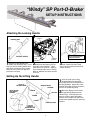
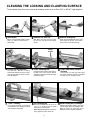
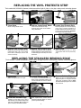
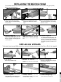
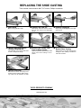
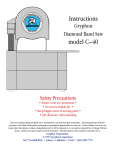
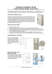
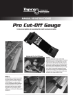
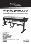
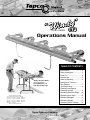
®�
PORT-O-BRAKE
Operations Manual
TABLE OF CONTENTS
“Windy” SP Port-O-Brake ®
shown with optional
Tapco PRO-Coiler ® and
Light Duty Folding Legs.
All Tapco Tools are made under
one or more of the following U.S. Patents:
3,161,223 4,321,817 4,651,553 4,489,583
4,493,200 4,445,356 4,372,142 4,766,757
3,817,075 4,557,132 4,240,279 4,671,094
3,482,427 4,494,397 3,559,444 5,343,728
5,353,620 5,505,069
Other U.S. & Foreign Pats. Pend.
Tapco Products Company
Introduction ............................. 2
Setup Instructions ................... 3
Parts List ................................ 4
Accessories ............................ 5
Hints for Bending .................... 6
Examples of Common
Trim Shapes ........................... 7
Troubleshooting ...................... 8
Cleaning Locking and
Clamping Surface ................... 9
Replacing Stainless Edge .... 10
Replacing Vinyl Strip ............ 10
Replacing Wedges ................11
Replacing Hinges ..................11
Replacing Shoe Castings ..... 12
INTRODUCTION
Congratulations on your purchase of a quality built Tapco Port-O-Brake®.
With proper care and maintenance, your Port-O-Brake® will provide you with
many years of excellent service.
This booklet will outline in detail the simple steps to properly maintain your
Port-O-Brake® and the proper procedure to use should your Port-O-Brake®
need repair. By following our General Hints you can prevent many costly
repairs.
If you find that your Port-O-Brake® needs a replacement part, it can be obtained by contacting your local distributor or by writing to us directly.
GENERAL HINTS
1. Clean your Port-O-Brake® at least once every 40 hours of use. Follow the
fast and easy procedure outlined on page 9.
2. Use a high quality cleaning solvent such as Gum-Out® or WD-40®.
3. Use only lightweight lubricants such as “3 in 1” Oil®, or 30 wt. oil. Note: Do
not use vasoline, axle grease, or graphite because they tend to “hold” dirt.
4. Use only clean shop rags that are free of dirt or metal chips.
5. Do not use your Brake around your saw table as the cuttings may get between clamping members and cause excessive wear or material scratching.
“WINDY” SP MATERIAL BENDING CAPACITIES
Soft Aluminum .................................... Up to .030
Hard Aluminum (Gutter Coil) .............. Up to .022
Steel* .................................................. Up to 29 ga
Galvanized Steel* ............................... Up to 29 ga
Copper Annealed ................................ Up to 12 oz
Copper Soft ........................................ Up to 24 oz
Vinyl .................................................... All standard
vinyl sidings
*Specifications may vary with temper of material
For Your Records
Complete the information below and save with this manual for future reference.
Date and Place Purchased
Model and Serial Number
2
“Windy” SP Port-O-Brake
®
SETUP INSTRUCTIONS
Attaching the Locking Handle
LOCKING
BLOCK
COTTER PIN
BEND ONE LEG OF COTTER
PIN OUT AFTER PASSING
THROUGH YOKE PIN
YOKE
LOCKING
HANDLE
YOKE
PINS
1
Remove Locking Handle and
Handle Grip from parts bag. Press
Grip over end of Locking Handle and
slide down until Grip is firmly seated.
Remove rest of parts from bag and
proceed to next step.
2
Insert bottom end of Locking
Handle into the bottom Yoke on
right side of Port-O-Brake.® Align
holes and insert Yoke Pin. Align top
hole in Handle with holes in Locking
Block of Slide Bar and insert second
Yoke Pin.
Setting Up the Lifting Handle
FACE OF
MOVING HINGE
MOVING HINGE
FASPIN
HEX NUT
SCREW
FASPIN
Insert Cotter Pins through holes in
ends of both Yoke Pins. Bend
one leg of each cotter pin forward to
secure Yoke Pin.
1
WASHER
ALIGN HOLES
AND INSERT
SCREWS
3
HANDLE PLUGS
LIFTING
HANDLE/
HANDLE PLUG
ASSEMBLY
3
Insert the ends of the Lifting
Handle/Handle Plug Assembly
up through the holes in the bottom of
the Moving Hinge. Align holes in the
Handle Plugs with the holes located in
the face of the Moving Hinge.
2
With holes aligned, insert screws
through Moving Hinge and into
Handle Plugs. Place washers over
ends of screws in back and tighten
with hex nuts. Handle can now be detached from Handle Plugs by removing
Faspins.
ACCESSORIES FOR YOUR “WINDY” SP PORT-O-BRAKE®
Pro-Coiler™
The portable coil holder that
becomes an integral part of your
“Windy” SP Port-O-Brake®
• Keeps the coil off the ground and always
in front of you
• Helps ensure you get straight cuts all the time
• Helps increase production and eliminate waste
• Holds 24” wide by 100ʼ coil
Hooks on and detaches in seconds.
Allows you to roll out and cut coil
squarely to your exact length.
“Windy” SP Port-O-Brake®
with optional accessories:
Pro-Coiler and Light Duty
Folding Legs
Change coils quickly by simply unhooking Roller Clip at one end and
inserting new coil.
Installing the Light Duty Folding Legs
Rail
Drill
361/2”
Mounting
Plate
Channel
Drill
361/2”
361/2”
nte
f
ro
Ce
Br
e
Mounting
Plate
ak
U Clamp
Drill
Mounting
Plate
361/2”
Leg
Plate
1
Center of
Brake
U Clamp
Drill
Leg Tubes
2
Position leg plates into
Invert Brake. From center of Brake,
mounting plate channels,
measure outward along each rail
align holes and install nuts and 361/2” and drill one pilot hole in center of
bolts provided.
each rail using an 11/64” drill bit.
4
3
Set legs onto Brake with leg tubes near drilled pilot
holes. Place “U” clamps over leg tubes, align holes and
install sheet metal screws. Drill re-maining holes through
clamps and install screws. Install screws also in mounting
plates as shown.
TRADITIONAL BENDING TECHNIQUES
Helpful Hints for Trim Work
1. Measure the total length of the particular trim area to be
covered and divide by the length of your Brake to determine
the number and length of trim pieces needed.
2. Determine the dimensions of each section of the desired
trim shape by measuring that particular profile to be covered. As an aid, make a pattern by bending a 1" strip of
coil to get your exact profile.
3. Transfer the dimensions in Hint #2 to each end of a piece
of trim coil by making a 1⁄4" slit in the metal with a pair of
shears. These marks now become the bending points and
are visible from either side. On longer lengths fold the coil
over as shown and snip both ends at once. This saves time
and ensures accuracy.
4. Lock the pre-marked coil blank into the Brake with the cut
marks located directly under the outer edge of the Stainless Bending Edge. Lock Brake. To cut off the coil with a
razor knife, score the metal against the Stainless Bending
Edge. Now bend the metal up and push back down by hand
until the exposed section breaks off. It may require 2 or 3
repetitions. When breaking material repeatedly, bending to
just 45° will avoid rounding the edge.
5. For some shapes you will be removing the piece and either
spinning it front to back or flipping it face up or face down
to make the next bend. Use proper care to avoid damaging
the piece especially on windy days.
6. Donʼt fit your trim parts too tight. This will complicate the joints
where parts overlap. A one inch (1”) lap joint is enough to
allow for expansion and contraction. Trim should be lapped
so that laps are facing away from traffic areas.
7. When face nailing try to nail the trim parts on an area that will
make the nails less conspicuous. Fasten at laps. Also when
face nailing, use just enough nails to secure trim; DO NOT
DRIVE NAILS TOO TIGHT or you will dimple the trim.
8. Remember, when designing shapes you are hanging a cover over the wood parts, not laminating a skin-tight surface.
This is called “Floating Your Trim”. Allow for irregularities in
the wood because your formed trim shapes are straighter
than the wood trim moldings or boards you are covering.
9. With practice, youʼll learn to overbend or underbend certain
sections to achieve a pressure fit of your trim parts which
will, in turn, require fewer nails and give your job a more
finished appearance.
10. Follow the suggested sequence of bends for the example
given or you may be “trapped” and unable to complete a
shape. Tailor the same steps to your own custom shapes.
Bending a Sample J-Channel
12"
Nailing Flange
2
GENERAL INSTRUCTIONS FOR ALL EXAMPLES
Exposed
Trim
Covering
12"
Siding
Pocket
Mark with pencil
then snip edges
1. This shape is basic to all other shapes made with the “Windy”
SP Port-O-Brake®. Take time to practice before you proceed
with other shapes.
2. To begin, cut off a piece of coil 4 inches wide by about one
foot long (as shown at right).
3. Place your tape measure on the coil and mark the coil with
a pencil at 3/4” and again at the 11/2” mark beyond that. Make
sure opposite sides are marked.
4. Now snip these marks as shown to the right so that they will
be visible on both sides of the coil (for some shapes you will
be turning your material both face up and face down).
5. Place sheet of coil into Brake with finished side down leaving
only first set of 3/4” marks hanging out. (Generally, insert the
largest part of the material into the Brake first.) Bend
is
at this mark so lock your brake on these marks and bend
90°.
6. Unlock the Brake and slide the material to the second set
of marks . Bend 90° again to complete the shape.
5
Finish�
Side Down
Finish�
Side Down
4"
Material: Aluminum coil 4”
wide by the desired length
(For this example 12” long)
1. Numbers show the sequence of bends; thus
would be the first bend and
the second.
2. “Finish Side Up” indicates that the finished or exposed side of the trim is to be put into the Brake
Facing Up.
3. “Finish Side Down” indicates that the finished or
exposed side of the trim is to be put into the brake
facing down.
EXAMPLES OF COMMON TRIM SHAPES
Illustrated below are typical shapes used on common siding jobs which you can form with the “Windy” SP
Port-O-Brake. The numbers indicate the recommended sequence of bends. “Finish Side Up” indicates
that the exposed or finish side of the trim material is to be placed in the Brake facing up.
DRIP CAP/SILL/MULLION
J-CHANNEL
1
Finish
Side
Finish
Side
2
1
LINTEL
BOX/DOOR CASING
2
1
Finish
Side
Down
FASCIA
Finish
Side
4
Finish
Side
Up
2
4
1
Finish
Side
Down
1
1
Finish
Side
Up
2
Finish
Side
Up
2
Finish
Side
3
Finish
Side
Up
Finish
Side
Down
Finish
Side
Down
3
Finish
Side
Down
4
Finish
Side
Up
INSIDE CORNER
3
Finish
Side
Down
2
Finish
Side
Finish
Side
Up
BRICK FRIEZE
Finish
Side
Down
FRIEZE
Finish
Side
Down
5
Finish
Side
Down
Finish
Side
3
Finish
Side
Up
Finish
Side
Down
3
2
Finish
Side
Down
Finish
Side
Down
Finish
Side
Down
Finish
Side
Finish
Side
Up
Finish
Side
Down
4
2
1
Finish
Side
Up
5
Finish
Side
Down
3
Finish
Side
Finish
Side
Down
6
Finish
Side
Up
Finish
Side
Up
1
Finish
Side
Down
TROUBLE SHOOTING
MATERIAL SLIPPAGE
Material Slippage is caused by the Brake not locking properly or fully along the entire length.
To determine the need for Wedge Adjustment:
A. Cut paper into sheets approximately 2” x 6”.
B. Insert paper into clamping position under each Shoe Casting.
C. Lock Brake
D. Try to remove paper while Brake is locked by lightly pulling on the paper. If paper slips
out easily, that particular Casting should be adjusted.
Solution:
A. Clean and lubricate Wedges, Sliding Bar, and Clamping Bar. (see page 9)
B. Tighten Fasteners for Hinges, Yoke, and Wedges.
C. Inspect Shoe Casting for damage due to dropping or other accidental abuse. Replace if
necessary (see page 12).
SCRATCHES OR MARRING OF MATERIAL
A. Do not use your Brake around your Saw Table as the cuttings may get between clamping
members and cause excessive wear or material scratching.
B. Wipe jaws clean during use to remove metal chips, dirt or shavings. This will prevent
scratching of your clamping mechanism.
C. If your material is getting scratched examine the Clamping Bar and Hinge for roughness
or burrs. Replace worn parts.
D. If you transport your Brake in the locked position, lock a piece of vinyl siding or cardboard
between the clamping members. Vibration during transport can cause scoring of the
clamping mechanism if dirt or foreign matter is present.
E. Replace vinyl strip if excessively worn or nicked.
UNEVEN BENDING
Uneven bending or “overbending” is material being bent more in one section that in another.
Solution:
A. Make sure material is being locked down securely prior to bending.
B. Using Brake on uneven ground may cause some bowing or twisting to occur.
C. Check fasteners on Fixed Hinge and Wedges for looseness and tighten. (see Replacing
Wedges page 11)
D. Check for cracked or broken Castings. Look on the top and underside of each casting.
Replace part. (see page 12)
E. Uneven bending may be caused by operator pulling on one end of the Lifting Handle
rather than the center.
F. Transporting your Brake other than in the flat working position may cause it to bow.
G. Look for bow along the Fixed Hinge and Clamping Bar. These parts may need to be replaced.
7
CLEANING THE LOCKING AND CLAMPING SURFACE
Tools needed: clean shop rag, commercial cleaning solvent such as Gum Out® or WD-40®, light weight oil
Brake
Top Yoke Pin
Sliding Bar
1 Open
2 Remove
3 Remove
Move Locking Handle to Right. Follow
With Brake unlocked remove Cotter
Grasp and pull Sliding Bar to the right
steps 1, 2, and 3 in reverse order to
reassemble.
Pin from Top Yoke Pin and disengage
handle.
and forward to remove. Turn upside
down and rest on brake castings.
Wedge
Screws
Underneath Clampin
Dirt and Residue
Clamping Bar
4 Loosen
5 Clean
6 Clean
Use Gum-Out , WD-40 or quality
Clean the bottom surface of the ClampSurfaces
®
®
commercial cleaning solvent on a clean
shop rag and clean the bottom surface
of the Sliding Bar.
ing Bar in the same manner. Before
reinstalling check that screws securing
wedges are tight.
Using solvent on a shop rag, clean upper
and lower clamping surface as indicated
and wipe dry. Do not apply oil here.
Clamping Bar
Sliding Bar & Oil Wedges
Cleaning
8 Oil
9 Replace
7 “Spot”
Using any lightweight oil such as
For everyday cleaning, a rag may be
Replace Sliding Bar making sure that
used between the clamping surfaces
with the Brake assembled.
“3 in 1”® or 30 Wt. motor oil, lightly
lubricate the Clamping Bar.
Note: Do not use graphite, silicone or
heavy grease as these “hold” dirt.
8
it slides easily along the Clamping Bar.
Wipe up excess oil. Clean and oil the
Wedges now and regularly thereafter.
REPLACING THE VINYL PROTECTO STRIP
Tools needed: drill, #26 drill bit, hammer, slotted screw driver, light oil, pliers or vice grips, center punch, and safety glasses
1 Close Brake
Move Locking Handle to left.
Vinyl Protecto Strip
2 Drill Out “Center Punch” Marks 3 Loosen
Push Vinyl Strip from one end by tapping
Clean out slots that hold Vinyl
Protecto Strip at both ends of Brake
using #26 drill bit.
on the edge of upright screwdriver as
indicated. Make sure opposite end of slot
is free of dirt and obstruction. CAUTION:
Avoid hitting hinge with hammer.
Vinyl Protecto Strip
Vinyl
4 Remove Vinyl Protecto Strip 5 Replace
6 Punch
Replace Vinyl Protecto strip by lightly luWhen Vinyl Protecto Strip is in place
Grasp other end of strip with pliers and
pull Protecto Strip out of slot. Check
slot for burrs, metal chips, dirt, etc. and
clean if necessary.
bricating leading end with small amount of
oil while sliding into slot. Wipe off excess
afterwards.
“center punch” both ends to prevent slippage.
REPLACING THE STAINLESS BENDING EDGE
Tools needed: slotted screwdriver, rubber mallet, vice grip or pliers, center punch, hammer, and safety glasses
Brake
1 Open
Move Locking Handle to the right.
Stainless Edge
Stainless Edge
2 Loosen
3 Remove
Grasp one end of Stainless Bending
To loosen old Stainless Bending
Edge, insert screwdriver behind one
end as indicated and twist to release
from end.
replacement, “Center Punch”
New Stainless Edge
4 Install
5 After
Stainless Bending Edge on ends to
Starting on end away from Locking
Handle align new Stainless Edge flush
with end of Clamping Bar and tap into
place sideways with Rubber Mallet.
prevent possible sliding.
9
Edge with pliers or vise grips and pull
away with a twisting motion. Note:
Stainless Bending Edge is not reusable
after removal.
REPLACING THE MOVING HINGE
Tools needed: electric drill, small drill bit, hammer, small diameter hard wire or narrow punch, vise grips or pliers,
light oil, and safety glasses
Handle
1 Remove
Detach Faspin and remove Lifting
Handle. Brake can be locked during
this operation.
Out Hinge Pin
2 Clean
Before removing Hinge Pin, drill out
“center punch” marks from ends of
Hinge.
Hinge Pin
3 Loosen
Using small diameter hard wire or narrow punch and hammer, tap out Hinge
Pin from one end.
Hinge Pin
Hinge
Hinge Pin
4 Remove
5 Remove
6 Replace
Grasp Hinge Pin at opposite end with
NOTE: Have an assistant support the
To install new Hinge and Hinge Pin,
pliers or vise grips and pull Pin out.
Moving Hinge will now disengage and
can be replaced.
Hinge prior to removing the Hinge
Pin.
have assistant hold Moving Hinge while
the Pin is inserted. When reinstalling
the Hinge Pin lubricate the leading
end with a light oil. Be careful not to
bend it.
REPLACING WEDGES
Tools needed: clean shop rag, Phillips screwdriver, commercial cleaning solvent such as Gum Out® or WD-40®, light weight oil
Brake
1 Open
Move Locking Handle to right.
Top Yoke Pin
Sliding Bar
2 Remove
3 Remove
With Brake unlocked remove Cotter
Grasp and pull Sliding Bar to the right
Pin from Top Yoke Pin and disengage
handle.
and forward to remove.
Wedges
Sliding and Clamping
Wedge
4 Remove
5 Replace
6 Clean
Periodically check to insure that screws
With the Sliding Bar removed and inverted
Bar Before Replacing.
as indicated, remove the Flat Head Screws
holding the Wedge to the Sliding Bar.
holding Wedges are tight. Loose screws
will cause uneven locking.
10
Clean surfaces. (see page 9)
REPLACING THE SHOE CASTING
Tools needed: socket wrench with 7/16” socket, Phillips screwdriver
Brake
1 Open
Move Locking Handle to right.
Top Yoke Pin
Sliding Bar
2 Remove
3 Remove
With Brake unlocked remove Cotter
Grasp and pull Sliding Bar to the right
Hex Head Screws
4 Remove
Holding Clamping Bar
Hex Screws from
5 Remove
Front of Shoe Casting
This will allow you to reach flat head
screws holding Fixed Hinge.
Pin from Top Yoke Pin and disengage
handle.
Remove Flat Head Screws from Fixed
Hinge on the Shoe Casting to be replaced.
and remove.
Hex Screws from
6 Remove
Back of Shoe Casting
Remove the four (4) Hex Head Screws
holding the Shoe Casting to the Bottom
rails front and back.
Pivot Arm
7 Remove
Remove Pivot Arms and springs and
replace the Shoe Casting. When replacing, make sure all fasteners are tight
TAPCO PRODUCTS COMPANY
A Division of Tapco International
www.tapcoint.com
TAPCO PRODUCTS COMPANY
©2003 Tapco International Corporation
11
Item #11102
T0069-L 9/03