1
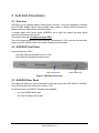
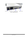
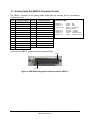
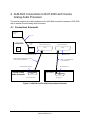
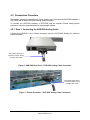
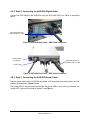
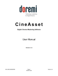
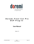
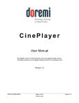
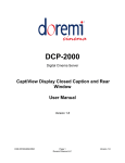
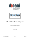
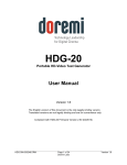
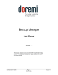
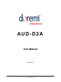
AUD-D2A
User Manual
Version 1.2
D2K.OM.000181.DRM
Page 1
Doremi Cinema LLC
Version 1.2
Table of Contents
1
INTRODUCTION................................................................................................................................... 4
1.1
1.2
2
AUD-D2A PRESENTATION................................................................................................................. 5
2.1
2.2
2.3
3
OVERVIEW ...................................................................................................................................... 5
AUD-D2A FRONT PANEL ................................................................................................................ 5
AUD-D2A REAR PANEL .................................................................................................................. 5
REAR PANEL CONNECTIONS ........................................................................................................... 7
3.1
3.2
4
PURPOSE ........................................................................................................................................ 4
PRESENTATION ............................................................................................................................... 4
AES/EBU DIGITAL AUDIO IN DB25-F CONNECTOR PIN-OUT ............................................................ 7
ANALOG AUDIO OUT DB25-F CONNECTOR PIN-OUT ........................................................................ 8
AUD-D2A CONNECTIONS TO DCP-2000 AND CINEMA ANALOG AUDIO PROCESSOR............. 9
4.1
CONNECTIONS SCHEMATIC .............................................................................................................. 9
4.2
CONNECTIONS PROCEDURE ........................................................................................................... 10
4.2.1 Step 1: Connecting the AUD-D2A Analog Audio .................................................................... 10
4.2.2 Step 2: Connecting the AUD-D2A Digital Audio ..................................................................... 11
4.2.3 Step 3: Connecting the AUD-D2A Power Cable ..................................................................... 11
5
DOCUMENT REVISION HISTORY .................................................................................................... 12
D2K.OM.000181.DRM
Page 2
Doremi Cinema LLC
Version 1.2
Software License Agreement
The software license agreement can be found at the following location:
http://www.doremicinema.com/warranties.html
Hardware Warranty
The hardware warranty can be found at the following location:
http://www.doremicinema.com/warranties.html
D2K.OM.000181.DRM
Page 3
Doremi Cinema LLC
Version 1.2
1 Introduction
1.1 Purpose
This document presents the AUD-D2A digital to analog audio converter. It also provides
explanation concerning the AUD-D2A connections between a DCP-2000 Digital Cinema Server
and an external Cinema Analog Audio Processor.
1.2 Presentation
This document is structured according to the following sections:
• Section 1: Introduction – Overall presentation of the document
• Section 2: AUD-D2A Presentation – Usage and characteristics of the AUD-D2A product
• Section 3: Rear Panel Connections – Presentation of the AUD-D2A rear panel
connections
• Section 4: AUD-D2A Connections to DCP-2000 and Cinema Analog Audio Processor –
Description of the connection steps
• Section 5: Document Revision History
D2K.OM.000181.DRM
Page 4
Doremi Cinema LLC
Version 1.2
2 AUD-D2A Presentation
2.1 Overview
AUD-D2A is an 8 channels digital to analog audio converter. It has been designed to interface
the DCP-2000 (Digital Cinema Server) digital audio output to Analog Audio Processors for
theatres without a Digital Cinema Audio Processor.
It accepts digital audio format signal (AES/EBU) as an input and outputs the same signal
converted into analog audio format.
The product ships with un-balanced output ONLY.
The unit has been designed to be rack-mounted. Its dimension is 1RU. It can be mounted either
close to the DCP-2000 or close to the Cinema Analog Audio Processor.
2.2 AUD-D2A Front Panel
Its front panel has 2 LEDs:
- one green LED showing when the unit is ON,
- one yellow LED showing the audio activity.
Yellow Activity LED
Green Power LED
Figure 1: AUD-D2A Front Panel
2.3 AUD-D2A Rear Panel
The back panel allows you how to connect the unit to the power outlet (100-240VAC / 50-60Hz).
It has a Power switch for turning the unit ON or OFF.
On the back panel, two DB25-F connectors are available:
-
one for the Digital Audio Input,
-
one for the Analog Audio Output.
D2K.OM.000181.DRM
Page 5
Doremi Cinema LLC
Version 1.2
Power switch
Power connector
Analog Audio Output
Digital Audio Input
Figure 2: AUD-D2A Rear Panel
D2K.OM.000181.DRM
Page 6
Doremi Cinema LLC
Version 1.2
3 Rear Panel Connections
3.1 AES/EBU Digital Audio In DB25-F Connector Pin-Out
The digital Audio Input connector pin-out complies with the AES/EBU standard and is illustrated
below:
Pin #
Signal Description
Pin #
Signal Description
1
no connection
14
no connection
2
no connection
15
no connection
3
no connection
16
no connection
4
no connection
17
no connection
5
no connection
18
no connection
6
no connection
19
no connection
7
Ch 7 & 8 plus
20
Ch 7 & 8 minus
8
Ch 7 & 8 ground
21
Ch 5 & 6 plus
9
Ch 5 & 6 minus
22
Ch 5 & 6 ground
10
Ch 3 & 4 plus
23
Ch 3 & 4 minus
11
Ch 3 & 4 ground
24
Ch 1 & 2 plus
12
Ch 1 & 2 minus
25
Ch 1 & 2 ground
13
no connection
DCI Channel Map:
Channel 1:
Channel 2:
Channel 3:
Channel 4:
L
R
C
LFE
Channel 5:
Channel 6:
Channel 7:
Channel 8:
Ls
Rs
Lc
Rc
(screen – left)
(screen – right)
(screen – center)
(screen – low frequency
effects subwoofer)
(surround – left wall)
(surround – right wall)
(screen – mid left to center)
(screen – mid right to center)
The cable that is used to interconnect the DCP-2000 to the AUD-D2A is a one to one pin
compatible.
A picture of the DB25-F input connector is provided below:
Pin 1
Pin 25
Figure 3: AUD-D2A Digital Audio Input Connector (DB25-F)
D2K.OM.000181.DRM
Page 7
Doremi Cinema LLC
Version 1.2
3.2 Analog Audio Out DB25-F Connector Pin-Out
The DB25-F connector for the analog audio output has the following pin-out (un-balanced
configuration only):
Pin #
Signal Description
Pin #
Signal Description
1
Ch 8 plus
14
no connection
2
Ch 8 ground
15
Ch 7 plus
3
no connection
16
Ch 7 ground
4
Ch 6 plus
17
no connection
5
Ch 6 ground
18
Ch 5 plus
6
no connection
19
Ch 5 ground
7
Ch 4 plus
20
no connection
8
Ch 4 ground
21
Ch 3 plus
9
no connection
22
Ch 3 ground
10
Ch 2 plus
23
no connection
11
Ch 2 ground
24
Ch 1 plus
12
no connection
25
Ch 1 ground
13
no connection
DCI Channel Map:
Channel 1:
Channel 2:
Channel 3:
Channel 4:
L
R
C
LFE
Channel 5:
Channel 6:
Channel 7:
Channel 8:
Ls
Rs
Lc
Rc
(screen – left)
(screen – right)
(screen – center)
(screen – low frequency
effects subwoofer)
(surround – left wall)
(surround – right wall)
(screen – mid left to center)
(screen – mid right to center)
A picture of the DB25-F output connector is provided below:
Pin 1
Pin 25
Figure 4: AUD-D2A Analog Audio Output Connector (DB25-F)
D2K.OM.000181.DRM
Page 8
Doremi Cinema LLC
Version 1.2
4 AUD-D2A Connections to DCP-2000 and Cinema
Analog Audio Processor
This section presents the overall schematic of the AUD-D2A connections between a DCP-2000
and an external Cinema Analog Audio Processor.
4.1 Connections Schematic
Power Outlet
100-240V AC,
50-60 Hz
Power cord
AUD-D2A
100-240V
0.5A MAX
50-60Hz
Power
connector
ON
POWER
OFF
ANALOG AUDIO OUTPUT
DIGITAL AUDIO INPUT
DB25-F
DB25-F
AUD-D2A Analog OUT
AUD-D2A AES IN
Cable 2: DCP-2000 Analog OUT to Cinema
Audio Processor IN SINGLE LEG
Cable 1: DCP-2000 AES OUT
to AUD-D2A AES IN
Cinema Processor Analog IN
Cinema Analog
Audio Processor
DB25-F
DCP-2000 AES OUT
DCP-2000
DB25-F
AES OUTPUT
ANALOG AUDIO INPUT
Figure 5: AUD-D2A to DCP-2000 Connections Schematic
D2K.OM.000181.DRM
Page 9
Doremi Cinema LLC
Version 1.2
4.2 Connections Procedure
This section presents the procedure to follow, step by step, to connect the AUD-D2A between a
DCP-2000 and an external Cinema Analog Audio Processor.
To connect the AUD-D2A between a DCP-2000 and an external Cinema Analog audio
processor, follow the steps presented in the paragraphs below.
4.2.1 Step 1: Connecting the AUD-D2A Analog Audio
Connect the AUD-D2A to the Cinema processor using the DCP-2000 Analog Out cable as
presented below:
“DCP-2000 Analog Out to
Cinema Processor Analog
In Single LEG” Cable
Figure 6: AUD-D2A Rear Panel – DCP-2000 Analog Cable Connection
“DCP-2000 Analog Out to
Cinema Processor Analog
In Single LEG” Cable
Figure 7: Cinema Processor – DCP-2000 Analog Cable Connection
D2K.OM.000181.DRM
Page 10
Doremi Cinema LLC
Version 1.2
4.2.2 Step 2: Connecting the AUD-D2A Digital Audio
Connect the DCP-2000 to the AUD-D2A using the DCP-2000 AES Out Cable as presented
below:
“DCP-2000 AES out to
AUD-D2A AES In” Cable
Figure 8: DCP-2000 Rear Panel – AES Cable Connection
Power button in
ON position
“DCP-2000 AES out to
AUD-D2A AES In” Cable
Power Cable
Figure 9: AUD-D2A Rear Panel – AES Cable Connection
4.2.3 Step 3: Connecting the AUD-D2A Power Cable
Plug the power cable into the AUD-D2A and power it ON by putting the power switch in the ON
position as presented in Figure 9 above.
The power LED of the front panel should light ON (green LED). If any activity is detected, the
“active LED” (yellow LED) should be lighted – see Figure 1.
D2K.OM.000181.DRM
Page 11
Doremi Cinema LLC
Version 1.2
5 Document Revision History
Date
Version
03/07/2008
1.0
First version.
08/07/2008
1.1
Audio output revised for default un-balanced configuration
07/15/2010
1.2
Balanced output option not supported anymore
D2K.OM.000181.DRM
Description
Page 12
Doremi Cinema LLC
Version 1.2