1
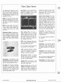
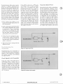
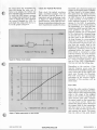
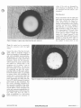
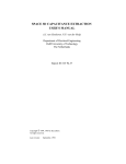
SERVICE INFORMATION FROM HEWLETT-PACKARD
2nd Quarter 1989
Brett Frymire
Hew lett-Packard
Your voltmeter no longer works. You
open the cover and begin to troubleshoot. You trace the fault to some
components with a plastic cable. What
is this? What do you do?
You have found a fiber-optic link that
has special parameters and requires
special test equipment. Follow along
as this article covers the parameters,
equipment, and basics of fiber-optic
troubleshooting, w i t h t i p s a n d
examples.
Background
Fiber-optic applications include isolation, video, audio or digital data
transmission, and LANs (Local Area
Network). In fact, the consumer electronics industry uses fiber optics to
isolate digital (TTL) from low-level
analog circuits. For example, a n
Onkyo Compact Disc (CD) player
uses fiber optics in this application.
CD players and the new DAT (digital
audio tape) both use this technology
for high noise immunity. Look for
modern stereo systems from Japan to
interconnect the CD player or DAT
to any other component with plastic
fiber optics. A new ANSI standard is
being developed for FDDI (fiber distributed data interface), which is a
100 Mbit/sec optical LAN.
As in consumer electronics, more and
more industry instrumentation uses
fiber optics (see Figure 1). A good
example of a n instrument-related
fiber-optic application is t h e
Safety Precautions
When Working
Around
Fiber Optics
[WARNING!
1)
Handle fiber-optic components with
care, keeping in mind the following
precautions.
The output from fiber-optic links can
cause serious damage to the eye,
and the glass in the cable can pierce
the skin.
Use caution when viewing fiber ends
or optical ports under magnification.
For further precautions and more
detail, see ANSI 2-136.1 1986.
(continued on page 3)
Use caution when viewing the optical
port without knowing the optical
power level and the wavelength.
Handle bare fiber with care. The
core end of the fiber is glass that
can pierce the skin and break off.
This is a hazard only when terminating a fiber end with a connector
or a splice.
Potential eye problems result from
invisible wavelengths, collimated
light, and light intensity of unknown
sources. As a rule of thumb, it is
always safer and more accurate to
use a meter to measure light output.
Figure 1. Typical HP fiber-optic products.
Pub. NO. 5952-0134
WWW.HPARCHIVE.COM
@ Hewlett-Packard 1989
Fiber Optic Terms
The following list defines a few of
the terms used in fiber optics. The
book, Fiber Optics Handbook,
available from Hewlett-Packard (HP
P/N 5952-9654),contains a more
detailed list of terms.
Eye Pattern: A term describing the
oscilloscope display when a data
pattern is triggered on the clock
signal. See the photo below.
Optical Power Budget: The calculated amount of optical power
needed to sustain correct operation
of the receiver, incorporating the
losses throughout the link. For example, the optical power out of the
transmitter minus the loss of the
cable minus any losses due to
splices or bulkhead connectors. If
the level of light falls below this
power level, the receiver output is
no longer valid. (See Sensitivity.)
BAUD: The symbol rate of the fiberoptic link. Depending on the encoding format, the symbol rate can be
the same or twice the apparent
signal rate.
BER: Bit Error Rate. The ratio of
errors to total number of bits sent in
a data stream, which defines the
quality of that data (e.g., BER
of 1x l E-7).
Bulkhead or Splice: A special connector that joins two cables. Generally, a bulkhead connector is used
when the cable has to pass through
a wall or partition. A splice repairs a
break in the cable. See the photo
below.
Fiber Optics (FO): The glass or
plastic medium used to transmit
signals between two points, or light
via an optical fiber. This term can
also refer to parts of the link (e.g.,
the cable, transmitter, receiver or
the complete circuit link).
FDDI: Fiber Distributed Data Interface. A proposed ANSI standard for
high speed fiber-optic LAN.
IF: The forward current through the
LED portion of the transmitter.
LAN: Local Area Network. A group
of terminals/computers linked together in a fashion to permit exchange of data with protocols.
Degradation: The tendency of the
light emitting diode (LED) to produce
less light with constant current (IF)
after an extended period of time.
Encoding: The process of translating data into a controlled average
duty factor range for use in an ac
coupled circuit. For example, NRZ
(Non-Return to Zero) data can be
sent as Manchester coded.
2
BENCH BRIEFS
milliwatts). Usually seen when referring to the output power of the
transmitter (Pt) or to the power
presented to the receiver.
Manchester Code: A coding
scheme that has two properties;
one, the average duty cycle is 50'10,
and two, it is self-clocking.
Optical Port: The portion of the
transmitter housing with which the
fiber-optic cable mates.
Overdrive: The tendency of the
receiver to produce erroneous or
distorted data when too much light
is presented to it.
Pr: The optical power presented to
the receiver.
Pt: The optical power at the
transmitter.
Sensitivity: The minimum optical
power level where the receiver is
guaranteed to have valid data. This
is usually specified at a particular
BER.
Underdrive: The tendency of the
receiver to produce erroneous data
when not enough light is presented
to it.
VF: The forward voltage across the
LED portion of the transmitter.
Wavelength: The optical spectrum
of the light emitted at the transmitter.
Optical Power (Pt or Pr): The
brightness, regardless of the wavelength of the light, measured in
either watts or dB (sometimes displayed as dBm, which is relative to
WWW.HPARCHIVE.COM
2ND QUARTER 1989
(continued from page 1)
HP 3458A Multimeter, where fiber
optics provide a data link for high
voltage isolation between floating
measurement hardware and the
HP-IB section. Traditionally, pulse
transformers have been used in this
area. Other applications also include
RS-232C (serial interface connection)
modules, such as the DOClO2P and
DOClOlP, which can be used for
higher noise rejection over long distances. Note that a standard hardwire
RS-232C connection is limited to approximately 50 feet according to EIA
(Electronic Industries Association)
specifications. The DOClO2P and
DOClOlP are good to approximately
500 meters. Hewlett-Packard's new
Precision Architecture computer uses
an optional fiber-optic interface for
the connection between the disk drive
and the CPU. The HP 37204A Multipoint HP-IB Extender also uses an
optional fiber-optic interface. Fiber
optics play a big part in isolating the
effects of TTL noise from small-signal
analog electronics. Possessing both
fiber-optic basic knowledge and
troubleshooting skills are valuable
aids that will help you repair instruments now and in the future.
Test Equipment
Troubleshooting fiber-optic circuits
requires specialized test equipment.
This equipment will allow you to
verify the light output of the transmitter, view the waveshape of the
optical output, accurately vary the
light amplitude (useful in troubleshooting the receiver), and substitute
your own optical signal.
Hewlett-Packard manufactures several products that can be used for
fiber-optic troubleshooting (see Figure
2), the first of which (and one of the
most important) is the HP 8152A
Optical Power Meter. This meter
measures light output (brightness)in
dBm so that optical power (Pt or Pr)
can be verified. The ability to check
correct optical modulation makes the
HP 81519A Optical Receiver very
important. Other equipment that may
prove helpful include the HP 8158B
Optical Attenuator, the HP 8154B
Optical Source, and of course, a good
dual-trace oscilloscope and digital
voltmeter (the HP 1980B Oscilloscope
and HP 3435A Digital Multimeter
are good choices).
Basic Troubleshooting
Procedure
Note: Each failure shown in the following figures is not an actual failure
but is a forced condition for example
only.
One important resource for troubleshooting is the databook from the
manufacturer on the specific parts
used. Databooks are inexpensive (free
to approximately $15.00) and provide
a wealth of data that are useful for
troubleshooting. Note that for troubleshooting purposes you only need
to look at typical values of the following elements.
VF (forward voltage measured
across the LED).
tr, tf (for both parts).
Pt for specific current.
IF (usually in graphical form).
Sensitivity of the receiver.
Attenuation of the fiber-optic cable.
Definition of a
Fiber-optic Link
Before we discuss fiber-optic troubleshooting and equipment, you need to
understand the basic components of
a fiber-optic link along with related
terms and acronyms that you will
encounter i n t h e course of
troubleshooting.
Fiber-optic links, as they are referred
to, are made up of three functional
blocks. The transmitter is the first
block, containing an LED (light emitting diode) and any needed support
circuitry to convert electrical signals
to light. The second block is the cable
and correct connectors for the link,
which carries the light signal from
the transmitter to the receiver, which
is the third block. The receiver consists of a photodiodelphototransistor
and support circuitry to convert the
light back to an electrical signal.
2ND QUARTER 1989
Figure 2. HP fiber-optic test equipment.
WWW.HPARCHIVE.COM
BENCH BRIEFS 3
Troubleshooting fiber-optic circuits
requires a logical, organized approach, just like troubleshooting other
circuits or instruments. (But be careful. Even though the approach is
similar to many other circuits, don’t
ignore the special safety precautions
associated with fiber optics. Remember that the fact that a fiber-optic
circuit is used may indicate the presence of a high voltage.) The following
steps show the order of the procedure
we will use to determine the failure.
1.First localize the problem. (Is it
located in the fiber-optic portion of
the instrument?)
If the LED is driven by a TTL gate
(see Figure 3A) or other voltage
source, the ac excursion will range
between ground and VF (1.5 volts), or
between Vcc and VF, depending on
the drive circuit used. For example,
a pre-bias circuit (see Figure 3B) can
affect the voltage swings in a different
manner. Pay attention to the dc voltage across the LED as the diode must
have a high enough VF to forward
bias the LED, approximately 1.5 volts
(a high VF or supply voltage at the
anode with the cathode near ground
would indicate an open LED). At this
point, any incorrect measurements
other than those listed would indicate
the support circuitry.
Check the Optical Power
Remembering the safety precautions
for the transmitter, separate it from
the rest of the circuit and check it for
correct operation as follows. Remove
the fiber-optic cable from the transmitter receptacle. You should use a
meter (HP 8152A or equivalent) that
is calibrated for the wavelength of
the LED to check the light output.
Do this by replacing the original
fiber-optic cable with a short, known
good cable approximately one meter
in length. Make sure the test cable
has the correct connectors for the
transmitter being tested. First, verify
an output then measure and record
2. Gather information about the problem without disturbing the circuit
or instrument. This is sometimes
referred to as milking the front
panel. (This assumes that the problem has been traced to the fiberoptic portion of the instrument.)
3. Using the test equipment mentioned earlier, isolate the problem
to one of the functional blocks of
the fiber-optic circuit (transmitter,
cable, or receiver).
4. Determine what is wrong with the
defective block.
Troubleshooting the
Transmitter
Figure 3A. Typical shunt drive.
Troubleshooting the transmitter is
divided into three parts; checking for
signals to the transmitter, checking
the optical waveform, and checking
the optical power.
Check Signals to the Transmitter
Probe the anode of the LED with an
oscilloscope. Does a signal exist at
this point? Depending on the support
circuitry, a current source might be
driving the LED. In this case the
voltage excursion (if it is measurable)
will be very small, on the order of 50
millivolts ac, which will ride on a VF
of 1-2 volts dc.
4
BENCH BRIEFS
Figure 38. Pre-bias circuit example.
WWW.HPARCHIVE.COM
2ND QUARTER 1989
the output from the transmitter for
later use during the cable test. If
there is no output, the failure has
been isolated to this functional block.
To verify the LED output, measure
the voltage loop containing the LED
(refer to Figure 3C), then calculate
the current through the LED (IF)
and check this value with the IF vs.
Pt on the graph in Figure 4.
Check the Optical Waveform
Next, check the optical waveform
with a waveform analyzer. Use the
HP 81519A Optical Receiver o r
equivalent and an oscilloscope (refer
to Figure 5 ) . While attaching the
optical receiver, verify that the oscilloscope termination matches the analyzer requirements (usually 50 ohms).
I
1
I
Example O f P e a k i n g C I r c u I t
-
Figure 3C. Peaking circuit example.
If possible, use a dual-trace scope and
trigger on the input signal. Compare
the input signal to the output signal.
The signal from the optical receiver
should match the signal seen across
the LED. Figure 6 is an example of
a good waveform. It will not be an
exact duplicate because of slow responses in the LED. In particular,
pay attention to the rise/fall times of
the transmitter, as a long fall time
(sometimes called long-tail effect) can
cause problems (see Figure 7). A
long-tail response can be recognized
by the characteristic changing slope
in the fall time. At approximately
the 20% point on the fall-time line,
the slope changes to a more gradual
sloped line. Usually the rise time on
a long-tail LED will also be slow, but
slow rises are usually fixed by the
designer using a peaking circuit (see
Figure 3 0 . A peaking circuit can be
recognized where the output of the
drive circuit is connected in series
with two resistors, one of the resistors
being bypassed with a capacitor.
When the first edge occurs there will
be a surge of current causing a fast
turn on of the LED. Unfortunately,
this does not help the falling edge.
Depending on the receiver, if the
long-tail response occurs near the
threshold of the amplifier/comparator,
noise (which rides on the signal) will
again pass through the threshold.
This will cause jitter o r multiple
switchings on the receiver output.
Examples of this problem will be
shown later.
The Cable
Testing the cable consists of comparing the optical output from the transmitter using a short and known good
cable to the output of the original
cable at the receiver. Using the one
meter known good cable, measure
the optical output at the transmitter
(as was done earlier when you
checked the optical power). Reconnect
the original cable to the transmitter
and then move to the receiver. Remove the cable end from the receiver
and measure the power. The power
from the cable at this point should
Figure 4. Typical output power vs. drive current.
2ND QUARTER 1989
WWW.HPARCHIVE.COM
BENCH BRIEFS 5
Table 1. Receiver data sheet specifications. This is a partial example from the HFBR-0501 Series Technical Data Sheet.
0°C to +70"C, 4.75 V s Vcc L 5.25 V Unless Otherwise Specified
Parameter
t
HFBR-2522
and
HFBR-2532
c
HFBR-2524
and
HFBR-2534
alcohol. If this does not fix the problem, use the following technique only
if the cable is glass and less than one
kilometer in length, or plastic and less
than 200 meters in length. Cables
exceeding these lengths will have to
be tested using another technique.
Remove the cable and hold one end
of the cable up to a light source. A
100 watt incandescent light works the
best. (A long cable will have an interesting effect. The light exiting the fiber
will be red for glass and green for
plastic.) An example of a good, clean,
defect-free fiber end is shown in
Figure 8.
If the cable is damaged or broken
and needs to be replaced, refer to the
HP Fiber Optic Cable Installation Guide
(HI' P/N 5954-0978) for installation
tips.
/7
Notes 2,
3, 8
-21.6
be sufficient to ensure correct operation of the receiver; that is, the power
should be above the sensitivity level
as listed in the data sheet (see
Table 1).If the power out of the cable
is below the minimum sensitivity
level of the receiver, and the optical
output for the transmitter is correct,
then either the cable has high attenuation or is broken.
t
t!
-21.6
HFBR-2521
and
HFBR-2531
Receiver Input Optical
Power Level for
Logic "0"
Rei.
+
Notes 2,
3, 8,9
t
'7
Figure 6. Example of a good optical waveform. Note clean pulse fall-time line.
If the cable has high attenuation, first
try cleaning the ends of the cable with
HP 54110A
~
u
u
n
n
Figure 7. Example of a poor optical waveform with a long-tail effect. Note slow falltime line that "breaks" at approximately the
20% point.
0 0 . 0 .
Fiber Optic/?
Cable
D.U.T.
Figure 5. Test equipment set-up for optical waveform test.
6 BENCH BRIEFS
WWW.HPARCHIVE.COM
2ND QUARTER 1989
I
either of the ends are damaged beyond cleaning or polishing, cut off
the damaged end and install a new
connector.
The Receiver
Figure 8. Example of a good, clean, defect-free fiber-optic cable end.
If the transmitter and the cable test
good, move to the receiver side of the
link. First, identify the type of receiver. If the receiver is a PIN photodiode, and depending on the support
circuitry, you may see a voltage of
200 millivolts, or a current of 100 to
400 nanoamps or less. If the part is
TTL, expect typical TTL levels. (Note
that some TTL parts require an external pull-up resistor.) Check the
output. Is a signal present? Is the
signal badly distorted? Does the part
oscillate or ring? Are there extra or
doubled pulses? Is there a spike on
the output? Is there jitter on the
Note: Be careful not to excessively
heat the connector with the light
source.
Inspect the ends of the fiber for dark
spots, chips or scratches. Figure 9
shows an example of a damaged fiber
end with embedded metal particles.
Magnification of at least 50x will be
required because of the small fiber
diameter (about 50-100 microns),
which cannot be easily viewed with
the naked eye. (Plastic fiber is the
exception as it is about 1 mm in
diameter.) Remember. Do not use
the transmitter as the light source
for inspecting the fiber (see accompanying article on fiber-optic safety).
If small scratches exist, it is possible
to remove them with polishing. Be
careful not to excessively polish the
connector as this increases the distance separating the cable from the
lens or IC, which increases the optical
power losses at the connection. Use
the correct polishing equipment for
the connector installed on the cable.
Any attempt to polish the cable without the fixture, which maintains the
cable and connector perpendicular to
the polishing paper, will increase the
loss. Make sure that the cable is
clean as polishing is a last resort
before installing a new connector. If
2ND QUARTER 1989
Figure 9. Example of a damaged fiber-optic cable end with embedded metal particles.
WWW.HPARCHIVE.COM
BENCH BRIEFS 7
edges? Are mysterious half or partial
pulses at half amplitude present? All
these Isymptoms hint at where the
problein lies.
As shown in Figure 10, output distortion c:m come from several areas.
Overdi‘ive, underdrive, receiver photodiodc3 failure, support circuitry, and
LED 1ong-tail effects are some of
the culprits. Underdrive caused the
wavefcirm shown in Figure 10.
Again, some of the same problems
that c;aused a distorted output can
cause extra or doubled pulses, as
shown in Figure 11. Overdrive, LED
long-tstil effects, and a faulty receiver
can ca.use this problem. In the example shown in Figure 11,overdrive
was th e problem.
Edges with excessive jitter (Figure
12) can be a hard problem to solve as
the cause can be one or a combination
of many defects. The first and most
obvious cause would be insufficient
optical power. After that it could be
Figure 12. This pulse edge with excessive
jitter caused by underdrive.
a bad receiver, open by-pass capacitor,
overdrive, long-tail effects, or any
part of the power supply filter. In
fact, the problem could be noiserelated where the metal ferrule of
the fiber-optic connector acts as an
EM1 source by inducing electrical
noise into the receiver. If the environment in which the fiber-optic link is
used is extremely noisy and a metal
ferrule is used, it is recommended
that a metal spring contact be used
to ground the cable’s metal connector
to the receiver ground plane (see
Figure 13). If this spring is missing
or has a poor connection, oscillations
can occur that may not be readily
visible on an oscilloscope. The symptoms may include ringing, overshoot,
or decreased sensitivity. Install a
spring if it is missing, or clean the
surface between the connector, metal
ferrule, and spring, or resolder the
spring to the printed circuit ground
plane. Another method that reduces
the effects of EM1 pickup by the fiberoptic connector is to use a connector
with a non-conductive plastic or ceramic ferrule. Note that some receivers incorporate a shield into the case
or housing of the component, so it is
important on these receivers that the
case is grounded. The example of
jitter shown in Figure 12 was caused
by underdrive, which could result
from either a contaminated fiber cable
or a weak LED.
Partial pulses (see Figure 14) is a
classic symptom of a long-tail effect,
although an open by-pass capacitor
or overdrive may cause a similar
effect. The problem shown in Figure
14A was caused by overdrive. The
problem shown in Figure 14B was
caused by a missing by-pass capacitor.
Figure 10. This severe pulse-width
distortilon caused by underdrive.
,
_.. *.*.
. .
SPRING IS SOLDERED
TO RECEIVER GROUND
PLANE.
THE OPTICAL FORT SO THAT F.O.
CONNECTOR IS GROUNDED WHEN
CONNECTED TO THE HFBR-2406/2416.
Figure 11. Extra or doubled pulses.
Receivc?r may be ringing or oscillating.
Overdriive caused this problem.
Figure 13. Metal spring used to ground cable’s metal ferrule to the receiver ground plane.
8
BEFICH BRIEFS
WWW.HPARCHIVE.COM
2ND QUARTER 1989
Figure 14A. This partial pulse caused by
overdrive.
You have now checked all parts of
the link. You checked the transmitter
for the correct light output and
verified the optical waveform, checked
the cable and finally the receiver.
Following these steps of fiber-optic
troubleshooting should isolate the
problem to the circuit or cable. I hope
that the information from this article,
plus reading the listed references
shows you that fiber-optic troubleshooting is straight-forward, and that
you can prepare for applications of
fiber optics in present circuits and
future uses.
For a thorough description/theory
of fiber optics, contact your local
Hewlett-Packard sales office and
order our Fiber Optics Handbook, HI’
P/N 5952-9654.
2. User’s Manual, Hewlett-Packard
HFBR-0100, Fiber Optic Connector
Assembly Tooling Kit, HP P / N
5953-9350.
3. Technical Data Sheet, The Versatile
Fiber Optic Connection, HFBR-0501
Series.
4. Application Bulletin 78, Low-Cost
Fiber-optic Links for Digital Applications up to 150 M B d , HP P/N
5954-8478.
5. Fiber Optic Cable Installation Guide,
HP P/N 5954-0978.
6. Hewlett-Packard Journal, J u n e
1989, Volume 40, Number 3, HP
P/N 5953-8575.
0
References
1. Fiber Optics Handbook, HP P/N
5952-9654.
Figure 148. This partial pulse caused by a
missing by-pass capacitor.
Need Any Sewice
Notes?
They’re free!
Here’s the latest listing of service
notes. They recommend modifications
to Hewlett-Packard instruments to
increase reliability, improve performance, or extend their usefulness.
Use the form at the rear of Bench
Briefs to order, free of charge, service
notes for several instruments.
2ND QUARTER 1989
If you would like to purchase large
quantities of service notes covering a
wide range of instruments, or if you
desire a complete history of all service
notes documenting all changes to
your instruments, Hewlett-Packard
offers a microfiche library for a one
time charge. There is also a microfiche
update service available that you can
order on a quarterly basis to update
the library.
The part numbers for the service
note microfiche library and subscription service are:
LibrarySubscription service-
5951-6511
5951-6517
Contact your local HP Sales Office
0
for ordering information.
WWW.HPARCHIVE.COM
HP 1345A DIGITAL DISPLAY
1345A-9. Serials 2619A and below. New A4 high
voltage power supply assembly requires new CRT
cable.
HP 2813B QUARTZ PRESSURE PROBE
28136-1. All serials. The possibility of high internal
pressure may cause a possible mechanical hazard.
HP 3235A/E SWITCHFEST UNIT
3235A/E-5A. All serials. HP 3235A firmware revisions.
3235A/E-6A. 3235A serials 2725A00626 and below;
3235X serials 2725A00562 and below. Additional
RAM (512K) is now available for the HP 3235A
processor.
HP 3552A TRANSMISSION TEST SET
3552A-18. All serials. Preferred replacement for capacitors A3C105 and A3C110.
HP 3561A DYNAMIC SIGNAL ANALYZER
3561A-3A. Serials 2338A01000 and above. 12 ROMS
replace 24 EPROMS on A40 processor assembly.
HP 3582A DYNAMIC SIGNAL ANALYZER
3582A-16. Serials 2602A07038 and below. Modification
that reduces occurrence of main line fuse blowing.
HP 3708 NOISE AND INTERFERENCE
TEST SET
3708A-13. All serials. Preferred replacement for A305R2
resistor.
BENCH BRIEFS 9
HP 3709A CONSTELLATION DISPLAY
3709A-8. All serials. Preferred replacement for transformer T1.
HP 3709B CONSTELLATION ANALYZER
37098-1. Serials 2723U00240 and below. Preferred
replacement for transformer T1.
37098-2. Serials 2723U00240 and below. Transformer
T1 retrofit procedure.
HP 3764A DIGITAL TRANSMISSION
ANALYZER
3764A-17A. Serials 26151101162 and below. Retrofit
kit to upgrade the features (including CCITT recommendation G821) on HP 3764A option 010.
3764A-19C. Serials between 2615U01162 and
2719U01637. Retrofit kit to upgrade the auxiliary
analog input.
HP 5335A UNIVERSAL FREQUENCY
COUNTERS
5335A-23. All serials. Tech tip to prevent degraded
sensitivity with special option Cio.
5335A-24. All serials. Preferred replacement part for
A9CR6 and A9CR7.
HP 5340A MICROWAVE FREQUENCY
COUNTER
5340A-228. Series prefixes 2250A and below. Preamp
retrofit kit.
HP 5342A MICROWAVE FREQUENCY
COUNTER
5342A-48A. All serials. Repair installation of amplitude
measurement opt. 002 (HP pin 05342-80505).
5342A-50A. All serials. Improved IF adjustment
procedure.
5342A-52. All serials. A22 motherboard replacement.
HP 3776A/B PCM TERMINAL TEST SET
3776A-33. All serials. Preferred replacement of protection devices on digital assemblies A7 and A12.
37768-39. All serials. Preferred replacement of protection devices on digital assemblies A107 and A1 12.
37768-40. All serials. Retrofit instructions for adding
option H01 (quantization distortion noise measurement) to the HP 37768 option H01 deletes the
return loss measurement and adds QD noise measurement capability in its place.
HP 5350/51/52A MICROWAVE FREQUENCY
COUNTER
5350151152A-7. All serials. LCD replacements kit. (HP
PIN 05350-60204)
HP 5350/51/52B MICROWAVE FREQUENCY
COUNTER
53501511528-7. Serial prefix 2810A and below. LCD
replacement kit PIN 05350-60205.
HP 3779C/D PRIMARY MULTIPLEX
ANALYZER
HP 5371A FREQUENCY AND TIME
INTERVAL ANALYZER
3779C-38. Serials 2520U00649 and below. Modification
to correct unstable CRT display (random lines and
"tearing").
37796-39. Serials 2520U00649 and below. Modification
to correct error R64 when performing Q-D noise
measurement on 900 ohm lines.
37790-40. All serials. A35 board-recommended replacement for fuses F1 and F2.
3779D-45. All serials. A35 board-recommended replacement for fuses F1 and F2.
5371A-8C. All serials with firmware revision 2828
installed. Firmware revision 2828 anomalies and
their workarounds.
HP 4192 LF IMPEDANCE ANALYZER
4192A-19. Serials 2514J05055 and below. How to
remove fuse A1 FI.
HP 4195A NETWORK/SPECTRUM
ANALYZER
4195A-1. Serials 2737J00219 and below (firmware
revisions 1.OO).Upgradingthe ROM-basedfinware.
4195A-2. All serials. Frequency response (phase shift)
adjustment in the network configuration.
HP 4947A TRANSMISSION IMPAIRMENT
MEASURING SET
4947A-8. Serials 27501100336 and below. Upgrade
instructions for adding the 2-wire return loss
measurement.
HP 4948A IN-SERVICE TRANSMISSION
IMPAIRMENT MEASURING SET
4948A-6. Serials 26151100395 and below. Recommended replacementiadjustment of power switch
cable.
4948A-7. Serials 2615U00365 and below. Preferred
replacement for fan.
HP 4954A PROTOCOL ANALYZER
4954A-4. Serials 2745A00600 and below. Modification
to prevent HP-I8 cable connector to disc controller
board from loosening.
HP 53168 HP-IB UNIVERSAL COUNTER
53168-1, Serial prefix 2816A. Modification to correct
SRQ HP-I8 failure.
10 BENCH BRIEFS
HP 5501B, 5517A/B, 5518A LASER HEADS
5501 8. 5517AI8, 5518A-1. See text for serials. Modification to correct fault in the high voltage power
supply assemblies that drive the HP Laser Heads.
HP 6944A MULTIPROGRAMMER
6944A-04. All serials. Isolating system failures caused
by termination plug.
HP 6954A MULTIPROGRAMMER
6954A-03. All serials. Isolating system failures caused
by termination plug.
HP 8447D/F AMPLIFIER 0.1 MHZ-1300 MHz
8447DIF-6A. 8447D serials 2648A and below; 8447F
serials 2634A and below. Replacement kit for
preamplifier, HP PIN 5086-7005.
HP 8554B SPECTRUM ANALYZER
85548-EA. Serial prefix 21 11A and below. Precaution
on changing A7 YIG oscillator assembly.
HP 8562A PORTABLE SPECTRUM
ANALYZER
8562A-28. All serials. Latest revision ROM upgrade
kit, HP PIN 08562-60062.
8562A-3. Serial prefix 2745A and below. 08562-60069
roller oscillator replacement kit.
8562A-4. All serials. Modification to the peak detector
top shield special screws (HP PIN 1390-0746).
8562A-5. Serials 2724A00885 and below. Modification
to prevent 80 kHz power supply sidebands.
8562A-6. Serials 2805A01787 and below. Improved
earphone jack operation.
8562A-7. Serials 2745A01523 and below. Preferred
replacement CRT filterifront frame assembly.
8562A-8. All serials. Tech tip for RF input attenuator
orientation for more consistent VSWR.
8562A-9. Serial prefix 2724A and below. Modifications
to prevent log amplifier oscillations.
WWW.HPARCHIVE.COM
8562A-10. All serials. Modification to prevent RF board
and top shield interference.
8562A-11. Serials 2750A01524 and above. Input connector replacement kit (HP PIN 5062-1 988).
8562A-12. Serials 2745A01523 and below. Modification
to prevent flashing display at power on.
8562A-13. Serials 2745A01523 and below. Modification
to smooth-out power supply start-up.
8562A-14. All serials. New power supply top cover.
8562A-15. Serials 2741 A01344 and below. Preferred
replacement of FL1 low pass filter.
8562A-16. Serials 2733A01023 and below. Modification
to eliminate spurs in the 600 MHz reference loop.
8562A-17. Serial prefixes 2724A and below. Modification
that improves frequency counter sensitivity
by -25 dB.
8562A-18. Serials 2724A00885 and below. Modification
to A9 input attenuator so that it sets to 70 dB at
power down.
8562A-19. Serials 2750A01694 and below. Preferred
replacement primary FET heatsink.
8562A-20. Serials 2724A00885 and below. New side
frames and cover assemblies.
8562A-21. Serials 2712A00901 and below. Modification
to prevent YTO loop overshoot.
8562A-26. Serials 2809A02037 to 2809A02837. Modification to reduce accoustically coupled 80 kHz
power supply sidebands.
HP 85628 SPECTRUM ANALYZER
85628-1 8.All serials Latest revision ROM upgrade kit,
HP PIN 08562-60062.
85628-2. Serial prefix 2745A and below. 08562-60069
roller oscillator replacement kit.
85628-3. All serials. Modification to the peak detector
top shield special screws (HP PIN 1390-0746).
85628-4. Serials 2724A00160 and below. Modification
to prevent 80 kHz power supply sidebands.
85628-5. Serials 2750A00128 and below. Improved
earphone jack operation.
85628-6. Serials 2745A00100 and below. Preferred
replacement CRT filterlfront frame assembly.
85628-7. All serials. Tech tip for RF input attenuator
orientation for more consistent VSWR.
85628-8. Serial prefix 2724A and below. Modification
to prevent log amplifier oscillations.
85628-9. All serials. Modification to prevent RF board
and top shield interference.
85628-10. Serials 2750A00201 and above. Input connector replacement kit (HP PIN 5062-1988).
85628-1 1. Serials 2745A00200 and below. Modification
to prevent flashing display at power on.
85628-12. Serials 2745A00200 and below. Modification
to smooth-out power supply start-up.
85628-13. All serials. New power supply top cover.
85628-14. Serials 2741 A00190 and below. Preferred
replacement of FL1 low pass filter.
85628-1 5. Serials 2724A00170 and below. Modification
to eliminate spurs in the 600 MHz reference loop.
85628-16. Serials 2724A and below. Modification that
improves frequency counter sensitivity by -25 dB.
85628-1 7. Serials 2724A00160 and below. Modification
to A9 input attenuator so that it sets to 70 dB at
power down.
85628-18. Serials 2750A00209 and below. Preferred
replacement primary FET heatsink.
85628-1 9. Serials 2724A00170 and below. New side
frames and cover assemblies.
85628-20. Serials 2724A00170 and below. Modification
to prevent YTO loop overshoot.
8562825. Serials 2809A00228 to 2809A00327. Modification to reduce acoustically coupled 80 kHz
power supply sidebands.
2ND QUARTER 1989
HP 8568A SPECTRUM ANALYZER
8568A-37A. All serials. RF attenuators must be replaced
with matching calibration ROM.
HP 8590A SPECTRUM ANALYZER
8590A-18. All serials. Instructions on replacing firmware
ROMS.
HP 8702A LIGHTWAVE COMPONENT
ANALYZER
HP 16500A LOGIC ANALYSIS SYSTEM
MAINFRAME
16500A-4. Serials 2650A00758 and below; serials
2650G00541 and below; serials 2650J00296 and
below. New disc drive shields for instruments requiring CPU board change.
16500A-5. Serials 2650A01200 and below; serials
2650G00561 and below; serials 2650J00329 and
below. Modification to insure fans start reliably.
8753A-11 A. Serials 2829A and below. Fan assembly
upgrade kit.
HP 16515A116516A 1 GHz HIGH SPEED
TIMING ANALYZER
HP 8753AlB NETWORK ANALYZER
16515A-1/16516A-1. All serials. Tech tip to prevent
ESD damage resulting from probe assembly
replacement.
8753A-5. All serials. Improving reliability of the A3
source assembly.
8753A-78. All serials. Modifications to improve A3
sourcelA9 C P U 1 A l l phase lock assembly
compatibility.
8753A-11 A. 8753A serial prefix below 2816A or 2950J,
and any prefix xxxxU. 87538 serial prefix below
2808A or 2828J. Fan assembly upgrade kit.
HP 8770A ARBITRARY WAVEFORM
SYNTHESIZER
8770A-3A. Serial prefixes 2726A and below. Synchronization and triggering capability retrofit.
8770A-6C. All serials. Firmware history and upgrade
procedures.
HP 8780A VECTOR SIGNAL GENERATOR
8780A-04. Serial prefixes 2725A and below. Cable
assemblies update and kit.
HP 8901B MODULATION ANALYZER
89018-3. Serial prefixes 2622A to 2833A. Modification
to resolve automatic tuning anomaly.
HP 8902A MEASURING RECEIVER
8902A-7. Serial prefixes 2621A to 2751A. Modification
to resolve automatic tuning anomaly.
HP 89036 AUDIO ANALYZER
8903B-3-S. Serials 281EA04250 thru 2818A04525.
Modification to prevent possible primary wiring harness shock hazard.
HP 8903E DISTORTION ANALYZER
8903E-3-S. Serials 281EA00325 thru 2818A00375.
Modification to prevent possible primary wiring harness shock hazard.
HP 8970AlB NOISE FIGURE METER
8970A-13. All serials. Improved measurement
repeatability.
89706-3. Serials 2745A and below. Improved measurement repeatability.
HP 10269C GENERAL PURPOSE PROBE
INTERFACE
10269C-1. Serial prefix 2723A and below; serial prefix
2723G and below. Modification to prevent "state
clock violates overdrive specification" error message
on 1650A151A151 OA logic analyzers.
HP 103146 80386 INTERFACE MODULE
103148-1. Serial prefix 2731A and below. Modification
to reduce target system clock loading.
2ND QUARTER 1989
HP 35660A DYNAMIC SIGNAL ANALYZER
35660A-02. See text for all applicable serial numbers.
Modification to add HP-IB power-up SRQ and revise
CPU test LED codes.
35660A-03. See text for all applicable serial numbers.
Firmware upgrade to prevent BASIC command
TRACE:DATA from returning error message.
HP 54100AlD DIGITIZING OSCILLOSCOPE
54100A1D-11. All serials. lncrrect sampler bias and
sampling efficiency adjustment can cause erratic
offset.
54100A1D-12. 54100A serial prefix 2812A and below:
54100D serial prefix 2809A and below. New ROM's
to eliminate intermittent loop failures at power up
and incorporate firmware feature upgrade.
HP 541 10D DIGITIZING OSCILLOSCOPE
541 1OD-11.
sampling
offset.
541 1OD-12.
cation to
trace.
All serials. Incorrect sampler bias and
efficiency adjustment can cause erratic
Serials 2633A00900 and below. Modifiprevent vertical gaps in the displayed
HP 541 11D DIGITIZING OSCILLOSCOPES
541 11D-8. Timebase accuracy performance test
change.
54111D-9. 10 MEG OHM 1O:l divider probes may
cause damage to the attenuators.
HP 541 12D DIGITIZING OSCILLOSCOPE
541 12D-3. ROM revision allows PaintJet support and
improves selftest reliability.
HP 64206A 6301Vl6303R EMULATOR POD
64206-4. 6301 Vi6303R emulation pod, all serials.
64206-66501 timing board modification to prevent
error message "HP-IB 110 failed, check power to
HP 64120':
HP 64207A 6301103X EMULATOR POD
64207-1. 6301103X emulator pod, all serials. 6420766501 timing board modification to prevent error
message "HP-IB I10 failed, check power to
HP 64120'1
HP 64262S, 8048 EMULATION SUBSYSTEM
64261A-2. Emulation control board serial prefix 2426A
and below. Modification to prevent 64261A (8048
microcontroller) high frequency port 2 failure.
HP 64700 SERIES EMULATORS
64700-1. 64700 power supply voltage selection
procedure.
64764AiAL-1164765A1AL-1. 64764, 64764AL and
64765A. 64765AL with serial prefix number 2739A.
Firmware upgrade to correct 64764165 background
monitor problem.
HP 70001A MAINFRAME
70001A-7A-S. Serials 2704A01437 and below. A possible shock hazard may exist in the HP model
70001A mainframe if safety earth ground is defeated
and there is a short on the +5 volt supply.
70001A-8. Serial prefix 2704A and below. Modification
to reduce fan noise.
70001A-9. Serials 2633A00112 and below. Modification
to prevent invalid overvoltage fault.
HP 70594A MODULE DEVELOPMENT KIT
70594A-1A. All serials. 418 module kit.
HP 70600A UW PRESELECTOR MODULE
70600A-1A. Serial prefix 2833A and below. Procedure
for replacing A12 or A13W1.
HP 70601A uW PRESELECTOR MODULE
70601A-1 A. Serial prefix 2743A and below. Procedure
for replacing A12 or A13W1.
HP 70900A LOCAL OSCILLATOR
70900A-3B. Serial prefix 2629A and below. HP 7090060096 memory-plus controller board upgrade kit.
70900A-17A. Serial prefix 2629A and above. HP 70900
OPT K91 RAMiROM board firmware upgrade kit
(70900-601 16).
HP 70905AlB UW MODULE
70905A-2A. Serial prefix 2821A and below. Procedure
for replacing A4 or W13.
709058-1A. Serial prefix 2819A and below. Procedure
for replacing A4 or W13.
HP 70906A UW MODULE
70906A-2A. Serial prefix 2813A and below. Procedure
for replacing A4 or W13.
709068-1A. Serial prefix 2805A and below. Procedure
for replacing A4 or W13.
HP 85629A TEST AND ADJUSTMENT
MODULE
85629A-1B. All serials. ROM upgrade kit (HP PIN
85629-60002).
HP 85650A QUASI-PEAK ADAPTER
85650A-7. Serials 600-1035, 1043, 1047. Modification
to prevent possible HP-IB hang-ups.
HP 64208A 6301103Y EMULATOR POD
64208-1. 6301103Y emulator pod, all serials. 6420866501 timina board modification to Drevent error
message ">P-lB 110 failed, check power to
HP 64120':
WWW.HPARCHIVE.COM
BENCH BRIEFS 11
c
NAME
COMPANY NAME
ADDRESS
CITY
STATE
0 8562A-05
0 85626-03
0 8562A-06
0 85626-04
0 8562A-07
0 8562A-08
0 85628-05
0 85626-06
0 85626-07
0 8562A-09
0 856214-10
0
0
0
0
8562A-11
8562A-12
8562A-13
8562A-14
0 85626-08
0 85626-09
0 85626-10
0 85626-11
0 85626-12
0
0
0
0
0
8590A-018
8753A-05
8753A-076
8753A-11A
8770A-03A
0 877OA-06C
0 8780A-04
0 89016-03
0 8902A-07
0 8903B-03-S
0 8562A-15
0 85626-13
0 8903E-034
0 8562A-16
0 85626-14
0 8970A-13
0 8562A-17
0 8562A-18
0 85626-15
0 85626-16
0 89706-03
0 8562A-19
0 85626-17
0 8562A-20
0 8562A-21
0 85626-18
0 8562A-26
0 85628-018
0 85628-02
0 85626-20
0 85626-25
0 85626-19
0 8568A-37A
ZIP
O 54111D-09
0 54112D-03
0 64206-04
0 64207-01
0 64208-01
0 64261A-02
0 64700-01
0 64764AlAL-01,
64765AlAL-01
0 70001A-07A-S
0 70001A-08
0 70001A-09
0 70594A-01A
0 10269C-01
0 103148-01
0 70600A-01A
0 16500A-04
0 16500A-05
0 16515A-01,
0 70900A-17A
16516A-01
0 35660A-02
0 35660A-03
0 70601A-01A
0 70900A-036
0 70905A-02A
0 709056-01A
0 70906A-02A
0 709066-01A
0 85629A-016
0 85650A-07
I
Please photocopy this order form if you do not
want to CUI
off t h e page
0 54100AlD11
0
0
0
0
54100AlD-12
54110D-11
54110D-12
54111 D-08
Bulk Rate
U.S. Postage
Sunnyvale, CA.
Permit No.
f
All rights reserved Permission to reprint Bench Briefs granted upon written request to the Editor
WWW.HPARCHIVE.COM
Printed in U S A .
2ND QUARTER 1989