1
February 2010
GFK-1775E
PRODUCT INFORMATION
READ THIS INFORMATION FIRST
Product:
DSM Module (DSM314) with Firmware Version 3.01
IC693DSM314-AE
IC694DSM314-AA
Because some of the information in this document is not available elsewhere, we recommend that you
read it and save it for future reference.
Release 3.01 of the DSM314 resolves the problem, described in “Problem Resolved by this Release” on
page 4, of inconsistent jump operation when executing consecutive CMOVEs. This firmware version
provides no new functionality.
Product Id:
IC693DSM314-AE/IC694DSM314-AA
H/W Id:
AP3B1 (44A737294-G01R03 or later)
S/W Id:
Firmware version: 3.01
App: 44F725986-417AE
Firmware Update Kit
If you wish to upgrade a previous version of DSM314 to firmware version 3.01, you may purchase upgrade
kit number 44A749487-G04, or download the upgrade free of charge from the GE web site at
http://www.ge-ip.com/support. Any previous version can be upgraded to 3.01.
Applicable Documents
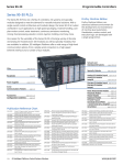
GFK-1742, DSM314 User’s Manual
Special Operational Notes
CPU Compatibility
The DMS314 can be used with the following CPUs:
IC693CPU350, IC693CPU352, IC693CPU360, IC693CPU363, IC693CPU364, and IC693CPU374.
Requires CPU firmware version 10.00 or higher.
Any IC694 CPU
Configuration and Programming Software Compatibility
DSM Model
IC693DSM314
Programming Software
CIMPLICITY Machine Edition version 2.1 or later.
VersaPro version 1.50 or later. Requires Electronic CAM function requires the
CAM Editor add-on version 1.0 or later, IC641VPSCAMA.
IC694DSM314
CIMPLICITY Machine Edition version 4.5 or later (includes CAM Editor)
2
Important Product Information
GFK-1775E
Essential Configuration Parameters
The following configuration parameters do not default to the settings required for many applications and
must be changed by the user or are features not available in this firmware release.
Motor1 Type,
Motor2 Type:
For digital servos, Motor Type must be changed to match the specific type number of the motor
used. Select type 0 only if no servo is used or in ANALOG mode.
Analog Servo
Command
Torque is supported in this firmware release.
Acceleration
Feed Forward
Percentage
Acceleration Feed Forward Percentage is not supported in this firmware release.
Feedback
Source
Feedback Source must use default or Ext Quadrature Encoder. Ext Quadrature Encoder is
used with Digital Mode Axis-1 only. Other choices are not supported in this firmware release.
Feedback Mode
If Feedback Source is set to Ext. Quadrature Encoder, then Feedback Mode is always
Incremental (even if set to Absolute).
Ramp Makeup
Mode
Ramp Makeup Mode must use Makeup Time.
Ramp Makeup
Velocity
The Ramp Makeup Velocity is used when the Follower Disable Action is Inc Position or Abs
Position and the follower slave axis reverses direction after a follower disable trigger. The
ability to reverse direction after a Follower Disable Trigger is an improvement in firmware
release 2.0.
PLC %Q Bits
PLC %Q bits are, by design, RETENTIVE in nature. These bits ONLY become NON-RETENTIVE after
their locations are used (programmed) in a PLC program. All motion causing %Q bits such as Drive
Enable, Start Motion program, Jog, etc. must be controlled from a programmed PLC coil reference for
safe operation.
Grounding Bars and Clamps
The DSM314 for IC693 PLCs User’s Manual describes the I/O cable grounding requirements required for
a system to meet CE Mark installation guidelines. These guidelines include the use of grounding bars and
clamps. A Grounding Bar may be ordered as part number 44B295864-001R02 and a Ground Clamp as
part number A99L-0035-0001.
Cables
Two I/O cables, two command cables, and one communication cable are available for use with the
DSM314, as described below. Consult the factory regarding custom length cables.
■
IC693CBL324: 1 meter terminal board connection I/O cable
■
IC693CBL325: 3 meter terminal board connection I/O cable
■
IC800CBL001: 1 meter servo command cable
■
IC800CBL002: 3 meter servo command cable
■
IC693CBL316: Motion programmer communications cable
Caution
The I/O and command cables listed above are custom manufactured with
special shielding and internal construction. Substituting nonapproved
cables may adversely affect the servo system.
Important Product Information
3
GFK-1775E
Terminal Boards
Two terminal boards for user I/O connections are available for use with the DSM314, as described below.
IC693ACC335: Servo terminal board
IC693ACC336: Auxiliary terminal board
These terminal boards provide screw terminal connections for I/O signals such as Position Strobes, Home
Switches, Limit Switches, Analog Inputs, and Analog Outputs. For additional information, refer to Chapter
3 of GFK-1742, DSM314 User's Manual.
Caution
The terminal blocks contain Metal Oxide Varistor (MOV) circuit protectors,
which prevent excessive electrical energy from affecting the DSM314. The
maximum recommended input voltage for any of the 24v I/O circuits is 30
VDC with respect to earth ground ("S" terminal) or circuit common.
Strobe Input Differences between Analog and Digital Mode
The strobe input faceplate pins for Axis 1 and Axis 2 depend on the DSM servo mode (Analog or Digital).
In Digital Mode, the Axis 1 and 2 strobe inputs use faceplate inputs IN1 and IN2, which can be either
single ended or differential. In Analog mode, the Axis 1 and 2 strobe inputs use faceplate inputs IO5 and
IO6, which are single ended only. Axes 3 and 4 always use IO5 and IO6 as the strobe inputs.
Note:
The input circuits for IO5 and IO6 contain 4.7k pullup resistors to internal +5v. If no signal is
connected to these inputs, the input will always appear to be ON. Normally a single ended TTL or
CMOS driver must be used to drive these circuits from the strobe sensor.
The strobe inputs are summarized in the table below.
Servo Type
Digital
Analog
Axis 1
Strobe Inputs
IN1_A, IN2_A
Axis 2
Strobe Inputs
IN1_B, IN2_B
Axis 3
Strobe Inputs
Axis 4
Strobe Inputs
(Single Ended
or Differential)
(Single Ended
or Differential)
IO5_A, IO6_A
IO5_B, IO6_B
IO5_C, IO6_C
IO5_D, IO6_D
(Single Ended)
(Single Ended)
(Single Ended)
(Single Ended)
Follower Disable and Abort Operation
When the follower function is active, the DSM Abort %Q bit DOES NOT disable the follower function. The
user can immediately halt motion by turning off the Enable Follower %Q bit. Thus, the Abort %Q bit halts
programmed motion, and the Enable Follower %Q bit halts follower motion. This operation is different
from DSM314 releases 1.0 and 1.1. In these earlier releases the abort %Q bit halted both programmed
motion and follower motion.
CAM in Absolute Mode can Lose Synch if Master Drive is Disabled
If the Master Drive is Disabled and then Re-enabled, the CAM axis will lose master counts that result from
master axis motion while the master axis is disabled. In Absolute mode, this can cause the CAM axis to
lose synch from the absolute master value. It is recommended that when the CAM command is operated
in absolute mode, the CAM be aborted when the master axis is disabled.
4
Important Product Information
GFK-1775E
Problem Resolved by this Release
Inconsistent Jump Operation when executing consecutive CMOVEs
When a motion program has a Jump command active during a CMOVE that results in executing another
CMOVE, operation of the servo motion should not stop if the latter CMOVE is valid. However, for certain
velocity and acceleration combinations, the DSM would incorrectly stop motion between the CMOVEs.
This has been corrected in firmware version 3.01
New Features and Functionality of this Release
None
Restrictions and Open Problems
Restriction/Problem
Cyclic Circular CAM with
Negative-going Master - problem
w/CAM blend and 2nd CAM is
ABS
Description
This problem is restricted to a cyclic-circular CAM in absolute master mode
in a sequence of CAMs with the master going backward: If the master has
already rolled over (moved a few counts) in the previous CAM and the slave did
not roll over (because the previous CAM exited), the slave will not automatically
rollover backwards into the next sequential CAM without an intervening Move
command. Otherwise, this could generate a velocity limit error as the slave
attempts to move without rolling over to the corresponding value matching the
current master position.