1
PC BASED DVR
DIGITAL VIDEO RECORDER
DVR
(Digital Video Recorder)
Integration
User Manual
MPEG4 Algorithm
User Manual v1.0
CHAPTER1:Features
…………………………………………………… 3
CHAPTER 2 :Main
…………………………………………………… 6
CHAPTER 3:Setup
…………………………………………………… 9
3-1. Disk Tool
…………………………………………………… 10
3-2. System
…………………………………………………… 11
3-3. Camera
…………………………………………………… 18
3-3-1. General
…………………………………………………… 18
3-3-2. Scheduling
…………………………………………………… 20
3-3-3. Color & Motion & PTZ
…………………………………………………… 21
3-4 Sensor
…………………………………………………… 24
3-5. User Admin
…………………………………………………… 25
3-6 Event Setup
…………………………………………………… 26
CHAPTER 4:Utility
…………………………………………………… 29
4-1. Backup Setup
…………………………………………………… 29
4-2. Setup Auto Backup
…………………………………………………… 31
4-3. Manual Backup
…………………………………………………… 33
4-4. Backup Viewer
…………………………………………………… 35
4-5. Auth Image Tool
…………………………………………………… 37
4-6. AVI Viewer
…………………………………………………… 38
4-7. Log Viewer
…………………………………………………… 39
CHAPTER 5: Search
…………………………………………………… 40
5-1. Smart Search
…………………………………………………… 45
5-2 POS data search
…………………………………………………… 46
CHAPTER 6:Features of DVR-Net
…………………………………………………
CHAPTER 7:Installation of DVR-Net
…………………………………………………… 49
CHAPTER 8:DVR-Net
…………………………………………………… 50
8-1. DVR Login Configuration
48
…………………………………………………… 50
8-1-1. How it works
…………………………………………………… 50
8-1-2. First time setting
…………………………………………………… 50
8-1-3. Re-Edit site information
…………………………………………………… 56
8-2. Accessing DVR-Net
…………………………………………………… 57
8-3. Local Search
…………………………………………………… 60
8-4. Remote Search
…………………………………………………… 61
8-5. Remote Setup
…………………………………………………… 62
8-6. Notification of event happing
…………………………………………………… 62
User Manual v1.0
※ Appendix ※
CHAPTER 9:Setup Dial-Up Server
…………………………………………………… 64
9-1. For Windows 2000
…………………………………………………… 64
9-2. For Windows XP
…………………………………………………… 69
9-3. DVR Setting
…………………………………………………… 70
CHAPTER 10:DVR Management
…………………………………………………… 73
10-1 Basic Settings
…………………………………………………… 73
10-2 Advanced Settings
…………………………………………………… 74
CHAPTER 11:User Define PTZ Protocol
…………………………………………………… 75
CHAPTER 12:Connection port
…………………………………………………… 83
12-1. Port and Function table
…………………………………………………… 83
12-2. Remote with Virtual-PC
…………………………………………………… 83
CHAPTER 13 : How to use DBTool
…………………………………………………… 85
CHAPTER 14 :Direct Web
…………………………………………………… 87
CHAPTER 15: HOW TO USE REMOTE
…………………………………………………… 93
SOFTWARE
CHAPTER 16: POS, Access Control,
…………………………………………………… 96
External Device Setup
16-1. Device Setup
…………………………………………………… 96
16-1-1. Select Device
…………………………………………………… 96
16-1-2. Create Database
…………………………………………………… 97
16-1-3. Events Setting
…………………………………………………… 98
16-2. ExDevice Setup
…………………………………………………… 99
16-2-1. Com Setup
…………………………………………………… 99
16-2-2. Lan Setup
…………………………………………………… 100
16-2-3. Display Setup
…………………………………………………… 101
Hardware Components
…………………………………………………… 102
User Manual v1.0
1. About Capture Card
▶ 1~16 Camera Input
Up to 16 camera input available for digital storage.
▶ 1~16 Sensor Input
Up to 16 sensors linked to the system.
▶ 1~4 Digital Output (Relay Outputs)
Digital Output can be used to activate things like siren… etc. and linked to sensor detection.
▶ Sound Recording and Two Way Communication
Sound can be recorded with video images, and mutual communication between DVR and
DVR_NET.
▶ Multi-Monitoring
The Multi viewing is selectable by one of 1, 4, 6, 9, 10, 16 camera video on monitor, enlarging
screen feature available.
▶ PAN/TILT/ZOOM/FOCUS
Support PTZ camera control by the DVR program
▶ Auto Rebooting System – Watchdog
When DVR detects a system error, it reboots automatically.
▶ Motion Detection and Sensor Triggering
Record images only by motion detection or sensor triggering.
▶ Scheduled recording
You can schedule the program to work only whatever you want, recording data only on specific
periods and days of the week.
▶ Data Backup and Auto Backup
Data can be recorded onto different media (like DAT, CD, or DVD), and you can specify the
camera to record, and the same for date and time. And scheduled recording means you can
automate the whole Backup process.
User Manual v1.0
▶ Digitalized Video Search
Recorded data can be reviewed in digital, each camera or all at a time, and you can specify the
date and time period of the search. You can also extract an image from the video to save
separately and print it out, enlarge and edit it.
▶ Network Support (TCP/IP Protocol)
By network support, you can log on to DVR from any remote site to search through and
download video data, and even change the settings of the program.
▶ Support POS SYSTEM
Record data from external devices (POS, Access Control, ATM, etc) with DVR video images.
Text Search allows to search data from external devices with DVR video image when event
occur. This will raise the level of integrity and security.
▶ Specifications
Feature
Specification
LIVE DISPLAY
Camera Input
1~16 Port (NTSC/PAL)
Sound Input
1, 2, 4, 16 Port
Sensor Input
1~16 Port
Relay Output
1~4 Port
TV Output
1 port
Compression
MPEG-4
Recording Mode
Watch, Normal, Motion Detection, Sensor, Scheduled Recording
Remote Control
Full remote control PSTN, ISDN,ADSL, LAN and TCP/IP
Back-up
DAT, CD, DVD
PAN/TILT/ZOOM/FOCUS
RS-232/422/485 Interface
User Manual v1.0
-
Main Board to be recommended strongly to use 865 PE Intel chip or above. The compatible exact
Model Name shall be inquired to Vendor.
-
Suggest use ASUS or GAGYBYTE motherboard
-
CPU that is lower than Intel Pentium-4
2.4 GHz could reduce the recording frame rate.
(Recommend 3GHz CPU)
- More than 256MB of memory, recommend 512 MB.
- Compatible platform: Windows 2000, XP.
-
I) Turn off System Standby mode.
II) Turn off Screen saver.
III) Turn off all the energy saving feature.
- System standby mode, monitor energy saving mode, and hard disk energy saving mode must be
“Disable”.
- Version No. of Driver and operating software must be noted separately for future up-grade service.
-
VGA card to be recommended latest version of ATI to be competent to the overlay image format.
-
Install Direct X 8.0 or higher.
User Manual v1.0
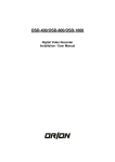
2. Main
G
J
A
B
C
K
I
E
D
H
F
Screen Division button for 1,4,6,9,16
A
Next Page / Auto Next Page/ Lager Screen /
Open PTZ&Image control panel.
Press “Emergency Record ” to force the continuous
B
recording of ALL CHANNELS MANUALLY, press again will
GO back to previous setting
Click the number button to turn on and off the corresponding
relay.
C
User Manual v1.0
Click the button to enter another DVR program.
D
E
Click Log In and enter the ID and password to login.
Click Log Out to logout.
F
Exit
2. The current date
and time
G
3. The used volumes /
1. Lit up during Backup
the total available volumes
4.Blinking while connected
Zoom in/out and Focus Near/Far.
Click + / - to change the ID of the
PTZ camera.
H
Click to start Auto Pan
P/T/Z Direction button.
User defined application keys
Image Control panel
User Manual v1.0
I
1. The top row: A blinking light indicates that the camera is enabled,
but no video received.
The bottom row: The box is lit up during recording, and the color
of the light indicates the recording mode.
Preset points, Preset function .
J
NOTE: All the PTZ function mentioned above depends on
if the PTZ PROTOCOL itself provides such capability.
K
Click the button and select channel,the sound will be
Broadcasted form the choosing camera
※On the 6 and 10 division image screen, if you want to have a larger image, click the right button
of mouse, located on that image screen. Then, that image moves to large image location.
※You can use F5, F6 as hot key for larger screen. F5 leads the enlarge screen but press F6 next to
F5, leads more larger screen.
User Manual v1.0
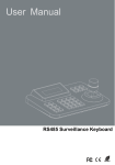
3. Setup
Start "DVR Setting", take note of the following appearance.
1
2
3
4
5
6
1. Disk tool - Create a file system. (Program will create its own file system, so that the large amounts
of data can be handled safely and it reduces the danger of system failure.)
2. System - Settings for network connection options, initial screen, sounds, automatic restoration, etc.
3. Camera - Set up of the cameras and the digital outputs and schedule recording etc.
4. Sensor- Settings for max.16 sensors.
5. Backup- Settings for automatic backup schedule.
6. User Admin - Different users are assigned to different access on DVR.
Note:
Even when you are doing some thing in Setting mode, DVR Main program still is working.
However, Prior to adjusting this “Disk Tool” only, you must stop Main Program because DVR
main Program may be in Recording status.
User Manual v1.0
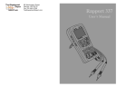
3-1. Disk Tool
1
2
3
4
6
7
5
8
11
10
9
1. Total Volume- The total number of all hard disk volumes
2. Current Volume –The used volumes
3. Total - The total capacity of hard disk.
4. Used Disk - Hard disk being used currently.
5. Usable Disk - The capacity of hard disk available.
6. Max Volume - The total number of Volumes available.
7. Used Volume - The number of Volumes being used.
8. Add Volume - Input the number of needed volumes.
9. Delete Volume- Discard all volumes from the selected hard drive.
10. Clear Volume – Clear all image data
11. Create Volume – Add Volume..
Enter the number of needed volumes on "Add Volume" and click "Add" button, check the correct number
appearing on "Add Volume" on the graph below, and click "Create Volume" button to create a file system
on the selected Hard Disk.
What is a Volume?
One (1) Volume equals to 65MBs of hard disk space. Motion Picture Data are recorded in these
volumes, and once a volume is completely full the program starts overwriting from the beginning
of the volume. (Important data better be backed up prior to this overwriting process.)
User Manual v1.0
3-2 System Setup
6
1
2
3
7
4
8
9
10
11
5
12
13
14
1. Site name: Key in name of the system, (This name for sending e-mail).
2. Site location: Name of the location at which the DVR computer is located.
3. Allow remote connections: Check on the box to allow connection from remote site.
Code: Give a unique combination of case-sensitive alphanumeric and numeric character.
(max. 10 characters)
4. Remote notification of events
-
Option of sending notification to where, in case of movement detection or sensor trigger.
Check if it allows notifying over network PC, where are known with IP address or the number
(Code) and installed with network program. The remote client is notified through sound and will
popup (if running and minimized)
Method :.
User Manual v1.0
In case of Modem, Ras user must be configured.
(Notice – If DVR server is running on Windows 2000/XP “Incoming connection” must be
created in “Network connection”. And make password(Ras user and password)
- Use IP Server
: If IP server is utilized, it will be much convenient in access to network without input frequently the
changed dynamic IP. This can be achieved by assigning the unique Code to the DVR and by configuring
that code number to DVR.
The default update time is one hour.
IP Server: Specially developed Program to control
Dynamic IP.
Notify interval: select IP address update time.
NOTE : 1. Code number shall be made with numeric and alphabetic within 10 digits, discerning
capital letter and small letter.
2. Users have to register the site name (code) before connecting to our IP server
(check chapter 16)
5. Log Write
: Record a Log file(Log can be viewed with Log Viewer in Utility.)
- System log : Time information of Main, Search, Setting start /end .
- Sensor log : Log for sensor detection.
- Motion log : Log for motion detection.
- User log : Log information of User login.
6. Screen
: Initial setting for main program.
- Initial screen : Number of camera shots that will be displayed when system is started.
- Normal, Large, Full : Size of the camera shots displayed when system is started.
- CCTV auto switching interval: The amount of time each camera shot will be displayed
intermittently through the Composite-Out port.
-- Normal : Displays the current camera shots of the monitor.
-- 1 View : Sequential switching of each camera .
-- 4 View : Sequential switching of 4 cameras.
- PC Screen auto switching interval: It sets the time between one screen division shot
and the next, only when the auto switching button function is activated
User Manual v1.0
7. Keyboard lock (Windows key disable / enable): Disables Windows Button from the
keyboard.
8. Enable hardware watchdog (Auto Reboot): Allows rebooting when system problems are
detected.
Note: For this, make sure “DVR Main.exe” to be set at “Startup“ of “Program” in Windows.
9. Schedule auto reboot of DVR : You can set the weekday and time, as you want, so that
DVR system can be rebooted automatically regardless of watch dog functions
10. Sound Recording
This option allows camera images to be recorded with sound.
- Installed Audio Devices : If there is 1 sound
device, up to 2 channels of sound recording is
possible.
If 2 sound device is available the it goes
up to 4 channels.
- Select Channel : Choose number of recording
sound channels.
-Select Camera : Selects the camera channel(s)
that will record sound with the accompanying
image recordings.
User Manual v1.0
* Connect to Audio
1 Channel sound
2 Channel sound
2
1
.
1) Connect to “Microphone In” of sound
card
1) Connect to “Line In” of sound card with
included 2 channel audio cable.
2) Connect microphones to the audio cable.
-
Must use amplified microphone.
4 channel sound
3
4
1) Additional sound card is needed (total 2
sound cards – 1 onboard and 1 PCI).
2) Connect “Line In” in both sound cards
with included 2 channel audio cable.
3) Connect microphones to the audio cables.
- Must use amplified microphones.
★ 1 = Microphone In
★ 2~4 = line in
Key of Notes
1. You shall install updated versions of Direct X than or equal to Direct X 8.0.
2. Do not forget to use the amplification microphone.
3. Two way communications shall be made one by one channel.
4. Do not use the same camera for different sound channel.
User Manual v1.0
11. Use E-mail
Method
--No SMTP : Find outgoing mail server(SMTP) automatically.
--SMTP/No Login : Use this option if you mail server is SMTP Server without Login process.
-- SMTP/Login/No RSA :
-- SMTP/Login/RSA :
-- SMTP/Login/RSA/MDS :
SMTP Server : Enter SMTP Server address.
User : Enter SMTP Server login User.
Password : Enter SMTP Server login Password.
From Address : The designated email address of the system.
To Address : The email addresses of the people who will receive email notifications from
the system.
Test : Test the email by sending an testing email.
User Manual v1.0
12. Warning on disk full
Whenever not more than the preset value in the volume unit or percentage was left in unrecorded
volume, you may have some warning against this by going off the warning on screen so that operators
can be ready to take measures against this.
- Warning at value;
- Last volume: if you check it, the typed figure is to become the preset value for warning.
- Specify the used percent: you can take the preset value by % of target volumes within the range of
90-99 %. The target volume, mentioned here, may be changed subject to next option in “Warning at disk”.
- Warning at disk
- Total disk: If you check this, above preset value, mentioned in “Warning at value” is to be regarded
against totally created volume in all of disk. For example, when you set the volume 100 in drive C, 200 in
drive D, the specified last volume is accounted as that against 300 volumes.
Current disk: If you check this, above preset value, mentioned in “Warning at value” is to be regarded ag
ainst the created volume in each of disk. For example, when you set the volume 100 in drive C, 200 in
drive D and currently DVR is using DB of drive D, the specified last volume is observed it against 200
volume in drive D.
User Manual v1.0
Warning at a term : This feature is made to give the alarm in advance when it comes to be reached at
the pre-schedule duration for recording in days.Firstly, pre-determine the required period for saving of
DVR data in days. When you wish to get the warning at the preset time before filling of disk, you can
input the desired preset time in hour: minutes.
- Start date: As for this purpose, It is the starting day in counting fro recording.
- Warning time : This is the warning time (hour; minutes) at calendar date to be due after “Saving
duration(days) “ since the saving has been started.
- Saving duration(days) : The target saving days.
Thus, this feature explains : when “Start date” is 2005/11/25 and “Warning time” sets as 09:00 and
“Saving duration (days)” is 10 days, then the warning goes off at 2005/12/5/ 9:00.
-Saving options on Warning : This is the options to accept or not the overwriting against the message
before it starts overwriting after DB volume has been filled.
- Save on warning: Checking allows overwriting DB files after volumes have been filled fully.
- No save on warning: Checking doe not allow overwriting on DB file. At this moment, the recording is
stopped no matter what the recording schedule was made.
- Disk Event : Configure event when message shows up.( Refer to Chapter 3-6)
13. Setting log off timeout : It is the valid time in minutes from login to logout. Only
during this period, all of key-in and configurations may be valid (indicated “log-out”). If
you want to set another after this set time has passed (indicated “log-in”), you shall be
required to input the log-in again.
14. Burn CD: Select CD burning program (CD burning program will start once CD Burn
button is selected in Search program)
Remember pushing the "Apply" button to complete the settings of individual camera.
User Manual v1.0
3-3 Camera
3-3-1 General
1
2
7
3
8
4
5
9
6
10
1. Select All : If selected, the settings selected in “General”, “Schedule”, “Color & Motion” will
be applied to all the cameras.
If you would like to customize each camera uniquely, select a camera from
the buttons on the left of the menu (1-16) FIRST, then choose the following
options
2. Enable Camera : Check the box to enable camera. (Ch1 camera is always enabled.)
User must exit the main program then set up this function under "DVR setting"
3. Camera Name :
Insert the name of the camera location. (Name will be displayed in Main screen.)
- Resolution: Choose the desired resolution for the camera. (Note: the higher the resolution
size of the recording will lead to a slower frame rate..)
**Data can be updated, but that will be applied from next time you restart main program**
4. Adjust camera frame rate
- Maximum averaged frame rate: Choose to record data on the Capture Card with the greatest
frame per second rate possible.
5. Select frame rate by camera: Set the number of frames per second to be recorded.
User Manual v1.0
6. Security
- Hide camera (Display): Choose to hide camera images from the PC monitor.
- Remove from CCTV display: Choose to block camera images from going out the
Composite-Out port.
- Remove from Network display: It makes the images not to send to DVR-Net .
7. Compression format & rate : change the compression rate.
Data can be updated, but that will be applied from next time you restart main program
8. Transmission format & rate
Choose the format
and the compression rate for the images transmitted through the network
program.
a. Data can be updated, but that will be applied from next time you restart main program
9. Post alarm recording
: In order to enable this, you should select “Motion” or “Sensor” in 'Scheduling' menu.
- Pre : Recording frame number prior to a Motion detection or Sensor trigger.
- Post : Recording frame number after a Motion detection or Sensor trigger.
10. Event notification
-Video loss - Notification : Choose event for Video Loss( Refer to Chapter 3-6)
Remember pushing the "Apply" button to complete the settings of individual camera.
User Manual v1.0
3-3-2 Scheduling
1
2
Choose the time (set by hour and day-of-the-week) for recording images of the camera from the
Scheduling menu.
1. Recording schedule
- Normal : All images captured on the camera is to be recorded.
- Sensor : Record images only when the sensor is triggered.
- Motion : Record images only when motion is detected.
- Display : Choose not to record images, just for view.
- Sensor & Motion : Record images when the sensor is triggered or motion is detected.
- Normal & Event: Record only one(1) fps(frame per second) when no motion (or sensor) is detected,
but continuous recording once when detection occurs.
2. Remote notify schedule
On this menu, schedule appropriate times in which the system should send remote notifications.
-
Notify : Press “Notify” and set up the desired time and day-of-the-week.
Remember pushing the "Apply" button to complete the settings of individual camera.
User Manual v1.0
3-3-3 Color & Motion & PTZ
3
1
5
4
2
This menu allows the user to control the color of the recorded images, modify motion detector
settings, and set up relay outputs (sirens, locks, etc.) for the system
1.
Event notify method
- When a video loss happen, relay out : Setup event of video loss.
(Properties : Refer to Chapter 3-6)
2.
Pan/Tilt Camera Method
- Use pan/tilt camera : Check this box when using PTZ cameras.
PTZ Camera : Choose the make and model of the camera.
PTZ_ID : Choose ID(address) of PTZ camera.
Connect Setting :Refer to camera manufacturer’s
documentation to set these values.
Speed : P/T-Pan/Tilt speed, F/Z-Focus/Zoom speed, A.PAutopan speed
(Depending on PTZ camera Speed might not be adjustable.)
User Manual v1.0
- Test : Test PTZ camera.
- RECEIVER : Choose PTZ camera
- PTZ ID : Choose ID of PTZ camera
- MANUAL SETTING : Selects the serial port that the camera uses to connect to the
computer. Refer to camera manufacturer’s documentation to
set these values.
- OPEN : Open the connection to take control of PTZ camera.
ARROW, FOCUS, ZOOM, AP, SPEED : Test each functionality.
- MENU : Bring the PTZ camera menu.(Depending on protocol it might not function.)
- TOUR : Tour the preset of camera.
- A1, A2, A3 : Test Extra feature of the PTZ camera.( Depending on protocol it might
not function.)
- Preset numbers 1~20 :
Move camera to each preset position.
- PRESET : Setup of waypoints can be done by doing the following:
1. Click “Preset” and press one of the numbered buttons.
2. Move the camera view to a desired location.
3. Click the same numbered button and the “Preset setup” again so that they
are no longer active.
- SCAN : Only available with camera that supports AutoPan scan function.
- START-Press START from the beginning position.
- STOP-Press STOP at the ending position.
- SEND : Manually give Hex value and send it to the camera.
User Manual v1.0
Support Protocol type
TYPE1=HRX-1000(Honeywell)
TYPE26=SSP(Samsung Protcol)
TYPE2=HRX-2000(D1)(Honeywell)
TYPE27=SPD1600(Samsung)
TYPE3=GC-655/755(Honeywell)
TYPE28=NKH-97CHE(NikoPT)
TYPE4=D-Protocol(Pelco)
TYPE29=CP-32M(CommaxPT)
TYPE5=HRX-2000(D2)(Honeywell)
TYPE30=MD-1000 Series
TYPE6=Panasonic
TYPE31=SecuMera Pro(TechnoVision)
TYPE7=Philips
TYPE32=HSDN-251(Honeywell)
TYPE8=Kalatel
TYPE33=WPT-101(Wonwoo)
TYPE9=Cannon
TYPE34=P-Protocol(Pelco)
TYPE10=PT102N(C&B)
TYPE35=SCC421(Samsung)
TYPE11=CRR1600i(Fine)
TYPE36=SJ3728R1(Sungjin)
TYPE12=DRX500(Dongyang)
TYPE37=Vicon
TYPE13=5-Series(Pelco)
TYPE38=SCC641(Samsung)
TYPE14=PIH7000(Lilin)
TYPE39=EVI-D30/31(Sony)
TYPE15=HSD251(Honeywell)
TYPE40=SRX100B(Samsung)
TYPE16=LPT-A100L(LG)
TYPE41=KRE301(Kodicom)
TYPE17=SERIM
TYPE42=ORX1000(Kodicom)
TYPE18=SpeedDoom Series(SensorMatic)TYPE43=KRE303(Kodicom)
TYPE19=DY255-DRXB(Dongyang)
TYPE44=Dragon
TYPE20=DSCP
TYPE45=THZ2201PT(American)
TYPE21=SAE Elec. SpeedDome
TYPE46=Echelon-9107
TYPE22=CRD-J6416
TYPE47=Vicon VPS
TYPE23=KPC-S38CZH
TYPE48=KSD-18DN(KODO)
TYPE24=StarPT
TYPE49=WSJ Series(Wonwoo)
TYPE25=CCD Control Box
3. Detection area setting
- Whole area : Detect motion at the whole area.
- Partial area : Click "Add“ and select specific area(s) to detect motion. Up to 10 partial
area selectable and delete them all by “Delete All".
- Display detected area : If selected, regions with motion activated can be tested for sensitivity.
any region with motion will show a group of red grid.
4. Motion setting
To receive desired optimal detection, configure the following options.
- Sensitivity adjustment : Adjusts the level of color difference detection between the
foreground and background..
- Rate of motion : Adjusts the rate of motion detected by the camera – if the number is
higher, the camera will be able to better pick up slower moving objects.
5. Color Control
- Brightness : Brightness
- Contrast : Contrast
- Saturation : Saturation
- Hue : Hue
- Default Value : Set to default value.
Remember pushing the "Apply" button to complete the settings of individual camera.
User Manual v1.0
3-4 Sensor
1
2
3
4
5
6
7
1~16 sensors can be connected, and sensor activation can be linked to Digital Outputs and cameras.
1. Selected sensor to use: Check the box of the chart on the bottom half of the screen to choose
specific group which sensors to use.
2. Sensor location : Input the position of the sensor.
3. Sensor type : Choose the sensor type being used. (Sensor activation: 0-NO, Sensor disables
while sensor activated: 1-NC)
4. Connected camera : Choose the camera to enable recording when sensor is activated.
5. Check time : Check for sensor movement every designated interval.
6. Emergency notify :Regardless of “Remote notify schedule” in “Schedule”, if you checked
“Remote notification of events’ in “System Setup” of Settings, Notification can be sent
on the event of sensor trigger, to the desired destination.
7. Properties Sensor : Choose event for sensor detection( Properties :Refer to Chapter 3-6)
Remember pushing the "Apply" button to complete the settings of individual camera
User Manual v1.0
3-5. User Admin
6
1
2
3
4
5
1. User Name - Input name of admin or user.
2. Password - Input password.
3. Confirm Password - Password for check.
4. Defaut user –when you log in DVR program, program will login with default user.
(Admin can’t set as “default user”)
5. Security Level - Select the level of the authority.
6. Authority - Assign the functions to which the admin. Will have authority.(if you set Network access,
you can set the user timeout for net-dvr login)
After filling the user information and checking the appropriate boxes, push the "Add/Modify" button to
register the admin. information. To change the status of an existing administrator, click on the
administrator from the graph and make the desired changes.
To delete an administrator or user, click on the desired admin. and push the "Delete" button.
Remember pushing the "Apply" button to complete the settings of individual camera
User Manual v1.0
3-6 Event Setup
Depending on events, different action can configured and take place.
ㆍ Beep : Play Beep on sound card.
- Use PC Speaker : Play Beep on PC speaker (Sound card is not required)
ㆍ Mark : Display Red dot on camera screen.
ㆍ Popup : Display 1 view Popup in the Main.
ㆍ TVout : Display the camera through Composite out for selected time period (in seconds)
ㆍ Second Screen : If system has second monitor, display popup on the selected coordinate of
second monitor.
ㆍ Remote Notify : Notify to the Net program(remote client).
ㆍ Use Notify Schedule : Use notify schedule (Camera – Schedule – Notify schedule).
ㆍ Relay : Output 1~4 Relay for desired Latch time(seconds).
User Manual v1.0
ㆍ E-mail : Send an E-mail. (In System setting email must be configured.)
- Subject : subject of email
- Content : E-mail content
- Attach Image : Attach video image.
- Interval : Email will be sent once for every selected time interval.
Note: This table will help complete the Subject and Content fields.
Reserved word
Contents
$$0
Camera No.
$$1
Events
$$2
Time
$$3
IP address
Example) Subject : “At $$2,
$$1 triggered at number $$0 camera.
Subject: “01-18-2005 19:10:12, Motion triggered at number 3 camera.
User Manual v1.0
ㆍ Preset : If selected sensor is tripped, this feature allows the selected camera to focus in
on the selected preset.
User Manual v1.0
4 Utility
4-1 Backup Setup
1
2
3
4
Recorded images can be backed up automatically if a backup schedule is set. Automatic backup is
enabled only after executing "Backup.exe" afterwards!
1. Backup Schedule
- Select Week : Select day of a week to start the backup.
- Select Time : Select time of a day to start the backup.
- Connected camera : Selects which cameras’ recorded images are to be backed up.
- Backup Device : Chooses the location where backed up data will be placed (default is C
drive). Data can be recorded on CD or DVD, and any media shown as
a storage device on the computer.
2. Schedule table
- Add/Modify : Add new/modified schedule in the list.
- Modify : After any changes applied to existing schedule click “Modify”.
- Delete : Delete selected backup schedule.
3. Start backup timer : Automatic backup will begin once the backup program is activated.
To verify automatic backup is taking place, check to see if the
backup program icon has been placed in the system tray
4. Overwrite when the disk is full : During automatic backup, hard disk will get overwritten if
it is full.(Overwrite starts from the oldest backup data.)
User Manual v1.0
Backup always starts from end of last backup session. (First time Backup will start from the
very beginning of recorded data)
When finished the Backup settings, be sure to run the Backup EXE file before starting the
main program, otherwise scheduled backup will not work automatically.
Remember pushing the "Apply" button to complete the settings of individual camera
User Manual v1.0
4-2. Setup Auto Backup
1. DVR-SettingÆBackup
A
B
C
D
E
F
A. select “week” “hour” and “minute”, Backup program will start backup at this time
B. select “connected camera” and “backup device”
C. Click “Add/modify” button
D. check “start backup timer”
E. select “Overwrite when the disk is full “ During automatic backup, hard disk will get overwritten
if it is full. (Overwrite starts from the oldest backup data.)
F. Apply
2. [Start]Æ[Programs]Æ[DVR SYSTEM]Æ[Utility]ÆBACKUP
A
A. Check “Auto startup enable”
B. click the button “Zzz” to task bar
B
User Manual v1.0
3. Then close DVR-Setting and execute DVR-Main
What is “Start backup timer”
Ex: Make backup at 12:00(Sunday) and set ”start backup timer”. It means
that DVR will make back up from 12:00 until next time of backup.
Make next backup at 18:00 Wednesday, DVR will record the backup
during 12:00(Sunday)~18:00(Wednesday) and start next backup.
3.DVR-main
When times up, the screen will like this.
User Manual v1.0
4-3 Manual Backup
A
B
Data can be backed up manually through this program simply by selecting the desired folders and
subfolders. This type of backup process allows selected data to be backed up.
ㆍ On the left window, choose the desired camera, date, hour, and minute to backup. The
progress is monitored at the right window.
A. Backup Directory : Destination of backed up files. CD, DVD, Network drive can be used.
Default Path : Click this to set the folder to default back up folder. Backup will store files in
this folder from now on.
B. Auto startup enable : By clicking this button, the Backup command is valid even though you
might reboot the system. At this moment, the tray icon for this shall be
seen at the screen bottom.
: Resets all settings.
: Start backup.
User Manual v1.0
: Stop Backup.
: Run Backup Viewer.
: Log for backup history.
: Standby mode for backup – setup this mode for auto backup to take place
: Exit from the backup program.
: Select “Start Time”, ”End Time” and “Camera” to backup.
User Manual v1.0
4-4. Backup Viewer
Backup Data can be reviewed with only the "Backup Viewer" program, on a search-by-date basis.
‘Date’ : Choose the specific date desired for search. If the
dates do not appear on screen, push the "Date" button
below.
‘Goto’: Directly to select date and time that you want.
“Smart Search”: Use for more quickly to find out
when the object moved.
"Save As" : to save the current image,
"Print" to print it out.
"AVI Save" button to save motion picture images from
that point to the point you choose to stop as an .avi file.
“CD Burn”: Start CD burning program
"Search" button to use the SEARCH menus,
"Image tool" button to use the Image Tools menus.
Image information display on/off button
You can take the data from the backup data as per every
date
User Manual v1.0
SEARCH menu appears as the "Search" button is pressed. You can play
images both forwards and backwards, and search image by image, also both
forwards and backwards
IMAGE menu appears as the "Image tool" button is pressed. Use the various
options (Zoom In/Out, Sharpen, Soften, B&W) to adjust the image.
Push to end "DVR Search"
Switch Camera mode and sound mode by double click.
Use the buttons to scroll through cameras 1~4, 5~8, 9~12, 13~16.
The camera number (numbers on the right), hour (numbers on the bottom), and minute (numbers on
the top) are indicated on the graph, and click the mouse to search the desired data.
On this menu, select time and date to be searched
directly and Click “GOTO”. Then the stored image
files appear if the stored data exists as effective of
that date and time. If not exists, the data, at the
closest to that date or time, are searched.
Refer to Chapter 5.Search
User Manual v1.0
: Remarks current searching point. (Bookmark )
: Displays list of Bookmarked searching point. Move to the listed point by Double click or
“Goto” button.
4-5. Auth Image Tool
This program deciphers images saved by the Search or
Backup Viewer Program, and tells you when an image has
been altered.
Open an image to decipher. With real unaltered
images, the image information appears as shown
above, but nothing appears for altered images.
Print image.
End program.
User Manual v1.0
4-6. AVI Viewer
This program allows you to watch Avi file saved as in MP4 type in Search or Backup Viewer.
However, if execution file is included while saving AVI, the file is saved as EXE file and has viewer inside
the file. Thus no other viewer is needed in order to see it.
: Open MP4 file.
: Play, pause, stop button
: Play by 1 frame at a time (back and forth)
: Adjust image size.
: Sound button. Press before play the video.
User Manual v1.0
4-7. Log Viewer
This program interprets Log file that is created during operation.
The log file contains following information.
1. Start and end of program (Main, Search, and setting)
2. Motion and sensor record (time and camera number)
3. User login and logout record
4. Disk warning message (DB overwrite warning message)
5. Video loss record
User Manual v1.0
5. Search
Search Single or Multiple
image data according to
date and time and
camera.
Desired images can be
saved separately and even
be printed.
I
‘Date’ : Choose the specific date desired for search. If the
dates do not appear on screen, push the "Date" button
below.
‘Goto’: Directly to select date and time that you want.
“Smart Search”: Use for more quickly to find out
when the object moved.
"Save As" : to save the current image,
"Print" to print it out.
"AVI Save" button to save motion picture images from
that point to the point you choose to stop as an .avi file.
“CD Burn”: Start CD burning program
"Search" button to use the SEARCH menus,
"Image tool" button to use the Image Tools menus.
Image information display on/off button
User Manual v1.0
SEARCH menu appears as the "Search" button is pressed. You can play
images both forwards and backwards, and search image by image, also both
forwards and backwards
IMAGE menu appears as the "Image tool" button is pressed. Use the various
options (Zoom In/Out, Sharpen, Soften, B&W) to adjust the image.
Push to end "DVR Search"
Switch Camera mode and sound mode by double click.
Use the buttons to scroll through cameras 1~4, 5~8, 9~12, 13~16.
The camera number (numbers on the right), hour (numbers on the bottom), and minute (numbers on
the top) are indicated on the graph, and click the mouse to search the desired data.
On this menu, select time and date to be searched
directly and Click “GOTO”. Then the stored image files
appear if the stored data exists as effective of that date
and time. If not exists, the data, at the closest to that
date or time, are searched.
CD BURN
Start CD burning program
User Manual v1.0
: Remarks current searching point. (Bookmark )
: Displays list of Bookmarked searching point. Move to the listed point by Double click or
“Goto” button.
When you click “AVI Saving", following menu appears, you can designate the camera No. and recording
start / end time, folder location to be stored and data type.
Now, press “Start” ,then AVI storage
becomes to start.
AVI Format : Normal AVI (.avi) file which can be
played with Windows Media Player.
MP4 Format : AVI file (.mp4) which only can
be viewed by AVI Viewer.
MP4+EXE Format : Self executable AVI file(.exe).
(No Player needed)
User Manual v1.0
Change Search mode to Common Search, Panorama Search or, Icon Search.
Common Search : Normal Search with Single and Multi-Search.
Panorama Search : Divide 1 camera recording into 16 multi view mode by each frame and
perform search .
Icon Search : Based on time, divide 1 camera recording into multi section.
Each screen
represents specific time and it can be divided even smaller time period. This search is useful
when user is not aware of time information of desired data. (24hour->10minute-> 1minute, Use
double click on left and right mouse button to navigate)
User Manual v1.0
1
2
0~24 hour
3
0~50 minute
4
0~9 minute
Final data search
User Manual v1.0
5-1. Smart Search
1
2
3
4
1. Date: date to be searched
2.Time: time to be searched
- From: starting Time to be searched
- To: ending time to be searched
3.Camera: camera no. to be searched
4.Rate of Motion: No. of recording
sensitivity at the area to be searched.
The Sensitivity are ranged to High:60,
Middle:40, Low:20. But by directly inputting
the value, the results may be different.
Note: The lower No. of “ rate of motion ”, the higher sensitivity it has , The higher sensitivity has more
precise detection. But it needs more data and takes more time to search.
Search
search the images per preset data.
Stop
It stops smart searching.
Clear Area
It deletes the designated area for smart search.
NO.
It indicates the total no. of image files searched by smart searching.
Skip Frame
If you feel inconvenient in handling the huge stored data, you can make the data
file reduced to compact data file by skipping as much as the set values.
These tab are used for “Play”, “reverse Play”, ”Stop” when searching data.
Save
It makes saving of data searched by smart searching function. (Save file is made
with .BMP.
Print
It prints the searched data by smart search function.
Close
Close the smart searching process.
User Manual v1.0
5-2 POS data search
Run Smart Search and click Text tab.
- Choose date, time and camera number to search.
- Select device.
- items: No condition – This will search every data that has been appeared in the time period.
Any match string – User can compose a string (in condition) to compare and search data
text.
* Event string – when event string has been registered in Device Setup, the event string appears
in items
Double click on one of searched result will bring a pop-up window as following picture.
User Manual v1.0
The size of pop-up window is adjustable to feed the demand of larger viewing. Click on one of four
corners to enlarge or shrink the picture.
This pop-up window allows play by frame, playback, and AVI saving.
User Manual v1.0
6.Features of DVR-Net
- Support of TCP/IP Protocol (PSTN, ISDN, ADSL, etc.)
Use any of the communication protocols to log on to DVR.
- Real-time Monitoring
Log on DVR-Net to monitor real time DVR images.
- Searching and Recording DVR data
Search recorded data in DVR, and save it in the remote site.
- Two-way Voice Communications
DVR-Net allows users to receive and send audio to DVR.
- PAN/TILT/ZOOM/FOCUS remote control
Control PTZ cameras remotely by DVR-Net.
- Change DVR Settings Remotely
DVR-Net enables users to turn on/off cameras, change recording schedules, and reset sensors
- 'Notify'(Automatic message alert from DVR)
DVR-Net is automatically started upon a DVR event, motion detected or an alarm triggered.
- Compatible O.S
Windows 2000/XP systems.
User Manual v1.0
7. Installation of DVR-Net
Click on 'setup.exe' and follow the messages.
You Need to restart computer
It shows at desktop after the installation is completed.
User Manual v1.0
8. DVR-Net
8-1 DVR Login Configuration:
8-1-1
How it works
DVR-NET
Create accounts of Login User
User A
User B
………..
Create the site informatio
Create the site informatio
n of the DVRs that User
n of the DVRs that User
A is going to connect
B is going to connect
8-1-2 First Time Setting
Step 1: Run DVR-Net and it pops out the following log-In window.
Step 2: Select New
4
1
3
2
1. New : Add a new log-in user and create DVR sites under this user name
2. Edit : Edit the DVR site configuration
3. Cancel : Exit without change
4. Minimized screen : Minimized the screen of system
Step 3: Input the user information: this is to set up the information of users that log in to the DVRNet
User Manual v1.0
1
2
3
4
1. Login name : Create an account of the Login User
2. Description : Describe the user.
3. Password : Assign a password to the user
4. Confirm P/W : Re-type the password
Step 4: Click OK to continue “Register site information” : click New to register the site
information of the DVR that is going to be connected.
1
2
3
4
1. New : Create a new DVR site .
2. Edit : Edit a site.
3. Delete : Delete a site.
4. Close : Save and Exit.
Note :
1. Site names are not allowed to be repeated.
2. Do not edit or delete any site while DVR-Net is running.
User Manual v1.0
Step 5: Register site information, and click “OK” to save the settings.
1
2
3
4
5
1. Site name : Create a site name.
2. Method : Select “TCP/IP” for LAN, Cable Modem, ADSL
Select “Modem” for PSTN Modem
Select “Server” for use IP Server.
3. IP/Tel no. : Input the IP address or telephone number (for PSTN/modem) of DVR
4. User name : Key-in the user ID that allows “Network Access” in your DVR “User Admin”
list
5. Password : Input the password of this ID
Connection by Modem, select method to Modem,click “property “ and type the contents at
dialogue box of “Ras User” and “Ras Password” like figures,depending upon OS types; Window98
or Windows2000 / XP.
If the DVR’s OS. is Windows9x, You should not specify anything
in dialogue box of “Ras User ” and “Ras Password” .
If the DVR’s OS. Windows2000/XP, You should specify anything
in dialogue box of “Ras User ” and “Ras Password”
Connection by IP Server, the Site Name will be the DVR’s code number which you want to connect.
Note
This “Site Name” must be exactly same with the code
set in the DVR
User Manual v1.0
Step 6: To re-edit or to delete the sites you just created: select the site and click Edit/Delete to reedit/delete the site.
Step 7: Repeat step 5 and 6 to create another new site.
Step 8: Click “Close” to save settings and continue.
Step 9: Click “Setup connecting mode”
1
2
3
4
5
1. Change login password : change DVR-NET users’ passwords.
2. Add, Delete and edit site information: register site information.
3. Setup connecting mode: set the connection mode, Single site or Multi sites.
4. Display configuration: setup the initial display screen, assign a directory to save data
and a file name to save system log, and setup whether and when to display caption.
5. Delete current user:
User Manual v1.0
Step 10: Setup “Setup connecting mode”: Select Single or Multiple, and check Initial Connect for
broadband users.
A
B
A- Single site connect: When there is only one DVR site to be connect and check
“Initial Connect”
z
When Initial connect Checked – suggest to check the box for broadband users
DVR-NET transmits video of all cameras automatically
z
When Initial connect Unchecked – Users have to click the camera button manually to
start video transmission
B- Multiple site connect: When there are more than one DVR site to be connected
** The following picture is just an example. Please enter correct site information.
1
2
3
1. Pos(Position): The channel number of DVR-NET.
2. Site name : Select the site to be connected.
** Not Used: if no site to be connected in this channel
3. Camera number(s) :
Choose the Camera Number of that DVR that you want to monitor in DVR-NET.
All: Show all cameras of that DVR site in this Position.
Partial: Display each camera auto-sequentially in the order you put down in this column.
You can set switch interval in the following step.
User Manual v1.0
Step 10: Setup “Display configuartion”: Choose an initial screen, assign a Save Directory and
create the log file name.
1
2
3
4
5
6
7
1. Initial view: Set the initial screen as full screen, quad screen, or other split mode, when
DVR-NET starts to run. There are 1, 4, 6, 9, 10, and 16 split mode to choose from.
2. Data location: It makes a set up of directory to be stored when clicks “Save”
under accessing to DVR-Net.
3. Log file: Create a file name to save system activity log.
4. Switching interval: Input the seconds of the switching interval.
5. On screen display: Image position No, site name, camera No/Name, can be
set-up in this mode.
6. Display Name: Choose when and whether to display the above information.
z
Always: Show caption all the time.
z
Only Mouse On: Show caption only when the mouse is moved to a certain channel.
7. Use IP Server: Check if IP SEVER shall be used.
- Code: Type the Code which was input at ‘IP/Num(Code)’when setting of ‘Remote
notification of events’ at DVR System.
Note:
1. Code no. shall be made with mix of alphabetic and numeric letter. Also it
discerns capital and small letter.
2. Do not confuse “Code” of ‘Use IP Server’ in Network setting of System
configuration in DVR system.
- Server: Address of IP Server
Step 10: Click “OK” to finish and close the configuration setting.
Step 11: Log In: Input your DVR-NET ID/PSW and click Login.
User Manual v1.0
8-1-3 Re-Edit Site Information
Step 1: Input your DVR-NET ID/PSW and then click Edit.
Step 2: Select the site you want to edit/delet and click Edit/Delete to re-edit/delete the site.
Step 3: Click OK to finish editting.
User Manual v1.0
8-2 Accessing DVR-Net
Please put “name & password” and click “Login”
B
A
B
F
M,N
A
L
C
D
K
A
H
G
J
I
It is for login and logout t o DVR-Net
-Date/Time: Present time and date indicated in the system.
-Login name: It says the registered User ID to be used in log-in
B
- Event Information: It can notify when an event
(Motion detection or Sensor activation) happens in
DVR.
C
D
F
It configure the information for log-in of DVR-Net
Save the images being transferred. (Search through the saved
data on Local Search)
Switching panel of Camera control (Pan/Tile/Zoom) and Image
control and Compression Rate.
User Manual v1.0
Preset point and Preset, Tour function
PTZ camera function and direction button.
P
T
Z
Buttons of the COMPRESSION RATE menu appear as the
"COMP Rate" button is pressed. Choose HIGH SPEED to
increase the rate of data transfer but decrease the image quality.
Choose LOW SPEED to do the opposite.
G
H
I
J
End DVR-Net
Local Search - Search through data saved on the DVR-Net
system
Remote Search - Search through data saved on DVR, and save
the data on the current computer
User settings Change the settings of the DVR through DVR-Net.
Enable voice communications with DVR. ("Sound Recording" on
K
the DVR User settings menu must be set on) Send Voice /
Receive Voice / Send and receive voice / cancel.
User Manual v1.0
L
While connecting to DVR-Net, if you point out the upper channel small box by mouse, the
connected site information such as IP address (Tel No), camera Number, validity of
connection. So it’s very easy to know who are connecting. Also, when pressing upper box of
camera, if it turns to apricot color button pressed, it means it is connected. Otherwise, it
means the connection is not valid
M
Relay state, you can turn it on or off manual.
N
Click the number button to turn on and off the corresponding
relay from DVR-NET
User Manual v1.0
8-3 Local Search
Its feature makes it possible to search the recorded data in DVR-Net.
On screen, if you press the button like a left-handed Icon, following box pops up
The name of system where the data recorded, are shown in lists. So, selecting the system which wish
to be searched in and check the option of “Saved while viewing” or “Save while searching” and press
“OK” as final.
Saved while viewing – It can make it recorded while watch the screen connected to DVR.
Saved while searching – It can make it recorded at DVR-Net while searching the recorded data in -DVR.
Most of operator is similarity Search program
User Manual v1.0
8-4 Remote Search
To search the recorded data in DVR by DVR-Net.
If pressing the button likes left-handed Icon, picture box like followings, will be shown.
After selected the site name, click “OK”, then following screen pops up.
Save the images being transferred as .DAT file.
The data saved by “Record” can be searched by “Local Search”
NOTE :
Local Search and Remote Search cann’t Play sound
User Manual v1.0
8-5 Remote Setup
It is possible to configure the DVR while presently connected with DVR-Net
: Press the left handed Icon on screen.
< Ref > : Please refer to the further detail procedure of configurations.
8-6 Notification of event happening
This feature is that event happening such as motion detection and sensor activation may be notified to
DVR-Net on real time.
The method of using this feature is as follows.
By press the Icon like left-handed picture, you can configure the system set-up of
.
DVR at remote location
Select “Remote notification of events”ÆProperties,
User Manual v1.0
At system setup, check “Notify remote site of any Events” on network and input the method of access by
TCP/IP or Modem in a line with IP address or Telephone No.
Next, it is required to set “Notify scheduling” on selected day of week in “Scheduling” of “Camera setting”.
It is easy to find out at what channel the event happens because the channel has specially image
boundary with red colors-line.
User Manual v1.0
9. Setup the Dial-Up Server
Attention: Before you start to setup it, please make sure that the Modem spec. is with the “Accept
incoming connection”.
To connect to DVR using a modem, a Dial-Up Server must be installed on the DVR. To
connect by using a modem, both of the DVR and DVR-Net must be equipped with a
modem. To connect with an IP address Both of the systems must have an IP address.
9-1 For Window2000
Click
Start > Setup > Control panel > Network and Dialup Connection and you can see follow screen.
Click ‘Make New Connection’ , then follow screen comes.
Click ‘Next’.
Select ‘Accept Incoming Connections’ and Click ‘Next’
User Manual v1.0
Selecting the proper modem on modem list, Click ‘Next’
(Following picture is sample for selecting “3Com” Modem.)
Select ‘Do not allow virtual private connections’ and Click ‘Next’.
Then, the Screen with ‘Allowed Users’ comes out.
User Manual v1.0
Here, you can add the user from Net viewer allowed to access DVR main. For this process, Click ‘Add…’
And now, Fill in the names of added were and password. Press ‘OK’.
When you finish to input user “1” to be accessed, then those allowed users are shown with ‘user 1’
currently input for example.
And now, Click ‘Next’.
Checking “Internet Protocol TCP/IP” and Press ‘Properties’.
User Manual v1.0
Checking “Allow callers to access my local area network” and In TCP/IP address assignment, check
“Specify TCP/IP address”
And now, fill the IP No of DVR main in blank of “From” while filling the IP No of Net Viewer in “To”.
Note: Because of Windows, the IP
address must be 192.168.55.1,
Otherwise it can’t be connection.
Designating TCP/IP add, Click ‘OK’ and ‘Next’ on following screen.
Then you can see following screen “Completing the Network Connection Wizard”.
Here, you can specify the connection name are you want and Click ‘Finish’.
User Manual v1.0
Now, you can see that Icon you have configured up to now, on following screen.
These procedures are described for installing dialup network server, only. So, the procedures for
accessing network viewer shall be referred to the related previous article.
User Manual v1.0
9-2. For Windows XP
Click Start > Setup > Control panel > Network Connection and then you can see follow screen.
Select “”Create a new connection”
Select “Set up an advanced connection”
Click ‘Next’.
Check “Accept incoming connection” and Click “Next”
Then, the other step as the same with Windows2000
User Manual v1.0
9-3 DVR setting
▪ A dvr-main setting
001
B DVR-NET setting
Execute dvr-net program
User Manual v1.0
User Manual v1.0
DVR-main’s
ID
and
Password
PS.User and password not dvr-main’s ID and password, those are dial-up server’s user and
password.
You can select “Single” or “Multiple” site Connection
User Manual v1.0
10. DVR Management
Run “START.EXE” , Then check
user dialog box will appear
- USER NAME : Type Name of Top manager .
- PASSWORD : Type Password of Top manager.
10-1. Basic settings
LIVE CAPTURE board
Note: Only when you change the dvr board can modify it, otherwise, change the setting will
Cause the dvr crash.
User Manual v1.0
10-2. Advanced settings
- Network Port Setup
- 1 ST ~ 4 ST : Type the port no. for Network.
1 st : for Image
2 nd: for PTZ and command
3 rd: for Setting
4 th: for sound
- Default : Click Default, Then it sets as default.
- WatchDog Option
- Interval Time: it sets the time of beep sound.
- Use Beep Sound : it allows to go off beep
sound by selecting “on”.
- When user finish program: it allows to go off
beep sound when program finish to run by
selecting “on”.
Upon finishing these configurations, Log-in with the user ID and password of top manager and tap “OK”.
User Manual v1.0
11. User Define PTZ Protocol
For define PTZ protocol, you have to refer PTZ’s data sheet, or contact with distributor.
Two file need to check,
One for option file, file location at <windows>\AngelCam.dat
Find [PT_INFO] section, and change the PT_CNT option and new PTZ name.
Other is in <Program Files\DVR System\PT> and make new file as the same with the other.
1. Section List
Section
GENERAL
Description
Settings of Parameter under Communication Backgrounds and Functional D
efinition of Pan / Tilt
DATA
Data setting of constant data and reserve data
DATAEX
Camera No., Preset No. and define Speed step
CAMERAEX
Define the extended camera no.
CHECKSUM
Formally define Checksum
SPEED
Define setting of Pan/Tilt, Zoom / Focus, Speed
COMMAND
Define functional Protocol format
COMMAP
Define Mapping Code of Command section Data
2. Section Detail
(1) “GENERAL” section
Key
NAME
SPEED
PARITY
DATABIT
STOPBIT
PRESET
AUTOSCAN
Description
Setting of Pan / Tilt Name
Setting of Baud rate
Available variable) 2400, 4800, 9600, 14400, ...
Set of Parity bit
Available variable) N (none), O (odd), E (even)
Set of Data bit
Available variable) 4, 5, 6, 7, 8
Set of Stop bit
Available variable) 1, 1.5, 2
Set of use / not-use of Preset function
Available variable) 0 (Not use), 1 (Use)
Set of use / not-use of Auto scan function
Available variable) 0 (Not use), 1 (Use)
User Manual v1.0
Set of use / not-use of Tour function
TOUR
Available variable) 0 (Not use), 1 (Use)
Set of use / not-use of Camera Menu feature
CAMERAMENU
Available variable) 0 (Not use), 1 (Use)
Example)
[GENERAL]
NAME = LilinPT
SPEED = 9600 //Use “baud rate 9600 bps”
PARITY = N
//No parity bit
DATABIT = 8
STOPBIT = 1
PRESET = 1
// Use the preset function
AUTOSCAN = 1
// Use auto scan function
TOUR = 1
// Use tour function
CAMERAMENU = 0
// Do not use Camera menu feature
(2) DATA section
Key
LEN
Description
Total No. of Data (or Last No.)
Settings of data
( format
[No. of byte], [one byte to be shown as 2 digits in hexadecimal ]
DATA[n]
( example
In case of express “abc”,
DATA1 = 3, 616263
* But, the value start from No. 1
Example)
[DATA]
LEN = 2
DATA1 = 1, 30
//‘0’
DATA2 = 4, 61626364 // ’abcd’
User Manual v1.0
(3) DATAEX section
Key
Description
Define Camera No.
format
[No. of byte], [ one byte to be shown as 2 digits in hexadecimal
CAMERA
], ...
* Up to 16 as maximum, Settings are available.
Define the Preset No.
PRESET
format
[No. of byte],[ one byte to be shown as 2 digits in hexadecimal], ...
* Up to 10 as maximum, Settings are available
Setting of basics and No. of Pan/Tilt Speed Step
format
[Total No. of step], [No. of basic step]
PTSPEED
* No. of step area integer and
ranged from 1.And No. of basic st
ep can never be more than No. of total step.
FZSPEED
APSPEED
PSSPEED
Setting of No. of Zoom/Focus Speed step and basic step
* same as setting of PTSPEED
Setting of No. of Auto Pan Speed step and Basic step.
* same as setting of PTSPEED
Setting of No. of Preset Speed step and basic step.
* same as setting of PTSPEED
Example)
[DATAEX]
CAMERA = 1, 31, 32, 33, 34, 35, 36, 37, 38, 39, 3A, 3B, 3C, 3D, 3E, 3F, 40
o. of #1 is
0x31 and that of #16 is 0x40
PRESET = 1, 01, 02, 03, 04, 05, 06, 07, 08, 09, 0A
PTSPEED = 7, 4 // Use step 4 among total 7 steps of speed level
FZSPEED = 7, 4
APSPEED = 7, 3
PSSPEED = 20, 10
//Camera N
User Manual v1.0
(4) CAMERAEX section
Key
LEN
Description
Total No. of data (or last No.)
Define Camera No.
format
CAMERA[n]
[No. of byte],[ one byte to be shown as 2 digits in hexadecima
l], ...
* Spread out up to 16 as maximum
Example)
[CAMERAEX]
LEN = 2
CAMERA1 = 1, 41, 42, 43, 44, 45, 46, 47, 48, 49, 4A, 4B, 4C, 4D, 4E, 4F, 50
CAMERA2 = 1, 81, 82, 83, 84, 85, 86, 87, 88, 89, 8A, 8B, 8C, 8D, 8E, 8F, 90
(5) CHECKSUM section
Key
LEN
Description
Total No. of step (or Last No.)
Formal Definition of Checksum
format
[data index], [No. of byte], [operation], [(1)additional value], [(2)o
peration], ... (repeat (1) ~ (2))
* data index are calculated from 0
* additional value
-
0 : when Single calculation is applied.
* operation value
CHECK[n]
-
-1 : no
-
0 : =
-
1 : +
-
2 : -
-
3 : *
-
4 : /
-
5 : ^ (exclusive or)
-
6 : ~ (not)
-
7 : | (bit or)
-
8 : & (bit and)
User Manual v1.0
Example)
[CHECKSUM]
LEN=2
// add 7 bytes from 1st data
CHECK1 = 0, 7, 1
CHECK2 = 0, 8, 1, 0, 5
// add 8 bytes from 1st data and make that value “ exclusive or”
(6) SPEED section
Key
LEN
Description
Total No. of data (or last No.)
Data Setting per speed step
format
SPEED[n]
[No. of byte], [one byte to be shown as 2 digits in hexadecima
l], ...
* Up to 16 step as maximum, Settings are available.
Example)
[SPEED]
LEN = 3
SPEED1 = 1, 89, 92, 9B, A4, AD, B6, BF // the value of 1st step is 0x89 and the value of 7th i
s 0xBF.
SPEED2 = 1, 89, 92, 9B, A4, AD, B6, BF
SPEED3 = 1, 0C, 18, 24, 30, 3C, 48, 54, 60, 6C, 78, 84, 90, 9C, A8, B4, C0, CC, D8, E4, F0
(6) COMMAND section
Key
LEN
Description
Total No. of data (or last No.)
Definition of command data
format
[No. of total byte ], [(1)data index], [(2)No. of byte], [(3)data val
ue], ... (Repeat (1) ~ (3) )
CMD[n]
* data index start from 0.
* data value
-
$d[n] : use the value defined at DATA section
-
$c : use camera No. defined at DATAEX section
-
$c[n] : use camera No. defined at CAMERAEX section
User Manual v1.0
-
$p : use Preset No. defined at DATAEX section
-
$s[n] : use the defined formula at CHECKSUM section
-
$s[n]1 : use low bit calculated by relevant formula
-
$s[n]2 : use high bit calculated by relevant formula
-
$s[n]3: character value of low bit of value calculated by rel
evant
formula
$s[n]4 : character value of low bit of value calculated by
-
relevant formula
-
$e[n]1 : p/t speed used the defined value at SPEED sectio
-
$e[n]2 : f/z speed used the defined value at SPEED sectio
n
n
$e[n]3 : auto scan speed used the defined value at SPEED
-
section
$e[n]4 : preset speed used the defined value at SPEED
-
section
But, n means the index value of key to be used for releva
nt
section
example
In case of ,
CMD1 = 3, 0, 1, $c, 1, 1, 04, 2, 1, $e11
,No. of total data byte is 3 and 1 byte from 1st index means
camera no.
1 byte from 2nd byte stands for 0x04 in hexadecim
al.
One byte from 3rd byte represents the value of P/T speed, w
hich brings value of SPEED1 key.
Index definition of command data to be used for stopping the rele
CMDS[n]
vant command.
* The Index value means Index defined at COMMAND section.
Definition of Repeat command
CMDEX[n]
format
[timer], [command index], [repeat count]
User Manual v1.0
* timer
-
setting as values in millisecond
-
-1 : no use
* repeat count
-
-1 : infinite
-
0 : no repeat
Example)
[COMMAND]
LEN = 21
CMD1 = 3, 0, 1, $c, 1, 1, 04, 2, 1, $e11
CMDS1 = 14
// Stop command of #1 command is used for the command data of #14.
CMDEX1 = 0, 1, -1 // Repeat command after #1 command, makes it continue to run #1 com
mand endlessly in 0 millisecond (without interval) until the next command or stop comman
d comes.
...
CMD8 = 8, 0, 2, AA5F, 2, 1, $e22, 3, 3, $d1, 6, 1, $c, 7, 1, $s1
// Length of total data is 8 bytes and 2 bytes from 1st byte are shown as 0xAA, 0x5F.
1 byte from 2nd byte means F/Z speed value which brings SPEED2 of SPEED section
and 3 bytes from 3rd byte bring value of DATA1 key of DATA section. 1 byte from 6th byte
means camera no. and 1 byte from 7th byte is value of checksum used formula CHECK1
of CHECKSUM section.
...
(8) COMMAP section
Key
LEN
Description
Total No. of data (or last No.)
Move Tilt up
CMD1
Setting of index value of command section, which are mapping with releva
nt command.
CMD2
Move Pan right, Tilt up
CMD3
Move Pan right
CMD4
Move Pan right, Tilt down
CMD5
Move Tilt down
CMD6
Move Pan left, Tilt down
CMD7
Move Pan left
CMD8
Move Pan left, Tilt up
User Manual v1.0
CMD9
Activate Auto pan (scan)
CMD10
Activate Focus in
CMD11
Activate Focus out
CMD12
Activate Zoom in
CMD13
Activate Zoom out
CMD14
Stop 1
CMD15
Stop 2
CMD16
Open command
CMD17
Close command
CMD18
Start Preset setting
CMD19
End Preset setting (or Saving)
CMD20
Activate Preset
CMD21
Remove all setting value of Preset
CMD22
Tour Set (tour set is made by all of set value for Preset)
CMD23
Activate Tour
CMD24
Set the starting of Auto Scan
CMD25
Set the ending of Auto Scan
CMD26
(auxiliary) Power 1
CMD27
(auxiliary) Power 2
CMD28
(auxiliary) Power 3
CMD29
(OSD) Camera menu display
Example)
[COMMAP]
LEN = 23
CMD1 = 1
CMD2 = 2
CMD3 = 3
...
CMD23 = 21
Attention:
Please refer the data sheet to make new protocol files; any of improper operation will
make PTZ devices damage and DVR program will crash.
User Manual v1.0
12. Connection Port
12-1. Port and Function table
For remote site connection, program using some port to transmit data.
Port number Type
Function
3000
TCP
Image
Changeable(1 st)
3001
TCP
Command/PTZ
Changeable(2 nd)
3003
TCP
Setting
Changeable(3 rd)
8800
UDP
Sound
Changeable(4 th)
4000
UDP
IP Server notify
Fixed
3005
UDP
Event notify
Fixed
If using same level networking, you don’t need to care about it.
But for the other, like Real-IP and Virtual-IP connection, or PC with firewall, you have to know
something about it.
12-2 Remote with Virtual-IP
In case of Remote site with Virtual-IP, you have to find out the IP-mapping at router.
For example, Router device: Speed Stream 2601
Supported function: NAPT (Network Address Port Translation), Host Mapping
1
2
Please refer the router manual for more detail about setting steps.
User Manual v1.0
In this case, there is two ways to do it.
1. Using NAPT, setup the port which you want to use at remote PC.
Remote’s IP address
Type and port number
2. Use Host Mapping, for all of the port to remote PC.
User Manual v1.0
13. How to use DBTool
Program default path is : C:\Program Files\DVR SYSTEM\DBTools.exe
1. This procedure is applied to the program version 4.00.01 or issued later.
2. This utility is requisite when the disk where database had been stored at, is moved to other
machine to be stored, and when you are going to search the database there.
3. Right after you transferred the data to other machine, you shall check in order to use the volume
data with this “Data Base Tool”.
4. Also, you can search the required data in the drive only as you want by utilizing this “Data Base
Tool”.
5. On the way of data searching, when you happen to encounter the same date’s data in different
drives, only the data of that drive, nearest to “A”, are to be searched out. For example, if “C” and
“D” drive has same date’s data and you try to search by selecting both of “C” and “D” drive, then,
search program performs at “C” drive first.
User Manual v1.0
z
DB file founded in Disk
-
Automatically scanning all of drives is system, this Tool indicates the list of the drives
contained the volume/database for DVR.
z
Check what drive you are going to make use of.
DB Information of the system
-
Press “↑”. And then the drive names checked in “DB file founded in Disk” is added on the
DB information list.
-
All of drive names checked in “DB file founded in Disk” shall be shown on this DB
information list.
z
Select a drive to start saving (recording) data
-
Make sure you must choose what drive it starts being stored (recorded) at, first.
- Example–
1. Data Searching after transferring one hard driver to other machine
(1) Install hard drives.
(2) Install software of DVR-main.
(3) Run the setup file, DBTool.exe.
(4) Check the drives shown in “DB file founded in Disk” or the drives you selected for searching
of particular data.
(5) Press “↑” button in order to add the checked drives to “DB Information of the system”.
(6) Press “Modify” after you select the drive of “Select a drive to start saving data” to be stored
(recorded) first.
(7) Press “Apply” to finish.
Note: Definitely make sure that the drives checked in “DB file founded in Disk” should be shown
in the drive names of “DB Information of the system”, too.
2. From now on, you can make use of data search and others, by running “Search “ program.
Note: “DVRDB” is the folder for “volumes”, generated by DVR program.
3. By copying just this folder to other machine installed with DVR program, you can use it as another
DVR system.
User Manual v1.0
14. Direct Web
14-1 Server
: Once Direct Web program was installed, the tray bar icon like the left side picture, is
generated. This program was installed automatically, along with DVR- main program.
Note: When there is any collision against the firewall or port in the server with Direct Web, click the right
hand button of the mouse on the tray bar icon and select “setting”. And now change the port.
As for root setting, you are recommended to use the defaults setting.
Note:Sometimes the port 80 will be collided,you can change other port number
14 -2 Client
When you input IP address of direct web on “ Address”, the following skin appears.
http://192.168.1.183
User Manual v1.0
Note:
You need to setting IE browser before you connect to DVR.
1. execute IE browser
2. [Tools]Æ[Internet options..]
3. [Security]
4. Custom Level
a. Automatic prompting for ActiveX controls--Æ”Enable”
b. Download signed ActiveX controls--Æ”Enable” or “Prompt”
c. Download unsigned ActiveX controls--Æ”Enable” or “Prompt”
User Manual v1.0
Click “Yes” to install “ActiveView.cab”
After you input the User ID and Password, authorized to access
DVR System, click ”LOGIN”. Then, you can be connected
The following picture shows the web view after you connected to the Server having Direct Web.
User Manual v1.0
These buttons are for the use of
1 channel , 4 channel
6 channel , 9 channel
10 channel , 16 channel
Swap
of
channel,Screen
PTZ control tabs are for the use of
Selection of camera No’,
Zoom Out / In
Focus Out / In‘
Moving of camera toward the arrow of t
he direction.
Selection of camera No’,
Brightness
Contrast
Saturation
Hue
Relay output
Enable voice communications with DVR. ("Sound Recording"
on the DVR User settings menu must be set on)
Send Voice / Receive Voice / Send and receive voice / Stop
User Manual v1.0
Search DVR’s image data
When use “SEARCH”,Browser will install “Angelcalc.cab”,click “yes” to installation.
User Manual v1.0
Click “AVI SAVING” and play through video and the video is saved as AVI file. To stop
AVI saving click “AVI SAVING” one more time.
Save image as .bmp picture
If you want adjust playing’ speed, you can set values for faster or slower
14 –3 Viewing AVI saved file information
AVI files that has been saved in DVR -Net or Direct Web includes information and this information can be
viewed in Windows Media Player with Captions On. (example – Windows Media Player 9.0)
User Manual v1.0
15 HOW TO USE REMOTE SOFTWARE
1.DVR SETTINGÆSYSTEM
a.Check “Allow remote connection”
b.input “code” for example: test001
2.DVR-NET
User Manual v1.0
test001
TCP/IP
Your ip address
Dvr ID
Dvr PW
You can select Single or multiple site connection
If you select mulitiple site connection,you need to check “POS”
User Manual v1.0
If your computer have firewall,you need open some port for DVR connection,
The table is port setting:
Port
number
Type
Function
3000
TCP
Image
3001
TCP
Command/PTZ Changeable(2 nd)
3003
TCP
Setting
Changeable(3 rd)
8800
UDP
Sound
Changeable(4 th)
4000
UDP
IP Server notify Fixed
3005
UDP
Event notify
Changeable(1 st)
Fixed
User Manual v1.0
16. POS, Access Control, External Device Setup
16 - 1. Device Setup
16 - 1 - 1. Select Device
Register POS or Access control device in the Map by pressing “>>” button.
*External device can be connected as many as number of cameras.
User Manual v1.0
16 - 1 - 2. Create database
Support type of database : Microsoft Access and SQL server
- Microsoft Access -
Select folder to create DB and click “Create Database”, “Test Database”, Compact Database in order
to create database and test it.
- SQL Server -
Fill out SQL Server name, DB name, User name SQL server and, Password.
Click in order : Create Database -> Test Database -> Compact Database
User Manual v1.0
16 - 1 - 3. Events setting
. After selecting Device click “Add” button to add event string.(case sensitive.)
. Select each registered even string and choose Notify method (Beep, Mark, Popup).
User Manual v1.0
16 - 2. ExDevice Setup
External device connects to DVR through both Serial port and TCP/IP.
Port Converter allows RS-422/485 and parallel connection.
16 - 2 - 1. Com Setup
Available ports are listed in the left side.
* If there are more External devices than available ports, extra COM port card
- Select the port where external device is connected.
- Select Device.
- Change the port setting to match up external device.
- After setting, test the connectivity of external device by “Test data Capturing”.
* if noting comes up in Test data capturing, correct the setting value and cable connection.
User Manual v1.0
16 - 2 - 2. Lan Setup
* Multiple external devices can be connected with single TCP/IP connection.
Each device must be given a unique port number.
-
Choose Lan from list.
-
Select Device.
-
Change port setting to match up the device.(support TCP or UDP)
-
Choose a camera(s) to display data from external device.
-
After setting, test the connectivity of external device by “Test data Capturing”.
* if noting comes up in Test data capturing, correct the port setting and cable connection.
User Manual v1.0
16 - 2 - 3. Display Setup
Setup the property of display of text data.
-
Choose camera number.
-
Font select: Click Browse and change font, size and color.
-
Text position: Setup the position of text.
Default is set to top of the screen. As number increases,
text will be displayed farther from the top.
-
Text duration: Set time for text to stay on screen.
-
Display lines: By transaction – Keep display text regardless number of lines until transaction
data has received.
lines – Set the desired line to displayed text.
-
Use overlay: When checked, camera image and data from external device is compound
together.(depends on external device, main display in device can be compound as well).
When
unchecked, they are not compound together. However, It is still possible to verify the data and
image together in the Search and remote access.
User Manual v1.0
Hardware Components
16 channel
Display speed
: 480 frame
Recording speed : 120 frame
16 channel
Display speed
: 480 frame
Recording speed : 240 frame
Accessories
Pigtail Cable
Audio Cable
Sensor Port
Sensor Cable
Reset Cable (Watchdog)
User Manual v1.0
Capture Card Layout
16 ch 120 frame capture board
WATCHDOG
Sensor/Relay
1
3
2
4
Pin No.
Description
1, 3
Reset
2, 4
Ground
To
motherboard
To case
TV-Out(Full
Screen, switch)
Pigtail Cable
User Manual v1.0
16 ch 240 frame capture board
WATCHDOG
Sensor/Relay
1
3
2
4
Pin No.
Description
1, 3
Reset
2, 4
Ground
To motherboard
reset pin
To case
TV-Out(Full
Screen, switch)
Pigtail Cable
User Manual v1.0
Connection
User Manual v1.0
Sensor Input and Sensor Output
Sensor input
Relay Output
User Manual v1.0
I/O Board
1
9
10
18
PIN NO.
Description
1~9
Sensor input 1 ~ 8
9
Input Ground
10~17
Sensor input 9~16
18
Input Ground
1
PIN NO.
Description
1,2
Output Ground
3
Relay output 4
4
Relay output 3
5
Relay output 2
6
Relay output 1
Relay connection note Contact Ratings: 30VDC 1A, 125VAC 1A
6
User Manual v1.0
POS connection
COM PORT
TDÆpin 2
Pin 2
RD
Pin 3
Connect to DVR COM1 or COM2
TD
RDÆpin 3
Select POS system protocol
Change the port setting to match up
POS external device.
Select Connected camera
User Manual v1.0
POS LAN
● ● ● ●
LAN1
LAN2
LAN3
LAN4,5….16
DVR LAN port
HUB
Change port setting to match up the
device.(support TCP or UDP)
Please refer to User_manual chapter 16 for detailed setup
User Manual v1.0
PDA-NET installation
a. Connect PDA device to computer(with cable or infrared)
b. If use infrared connect to PDA, you need install “PDA_MSASYNC.EXE” to your computer first.
(you can find this program in our CD)
c.
Install “PDA-Net.exe” from our CD
d. Finish install, then check your PDAÆ program, you can find PDA-NET
e. input DVR’s IP Address, user name and password, then login
PDA-NET only support Microsoft Pocket PC(windows CE)
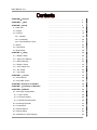

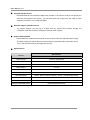
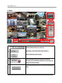
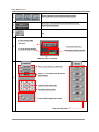
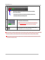
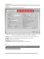
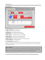
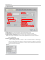
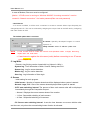
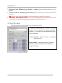
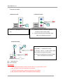
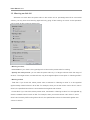
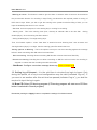
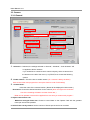

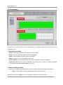
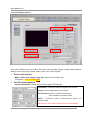
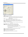
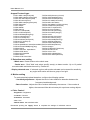
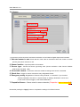

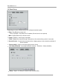

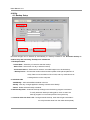

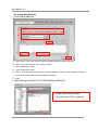
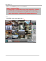


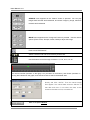


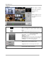
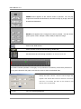
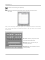
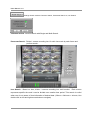
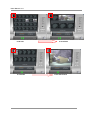

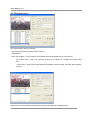
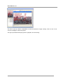

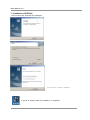
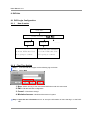
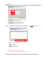
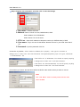
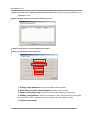
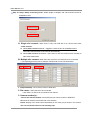
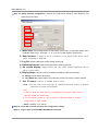
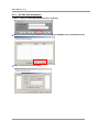
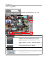
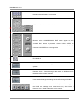

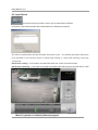
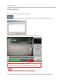


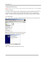
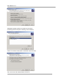

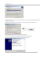
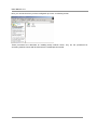

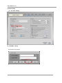
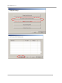
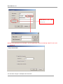

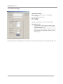
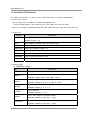
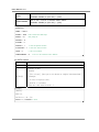


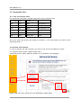
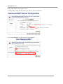

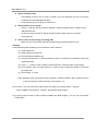


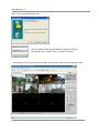
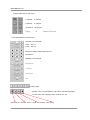
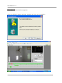

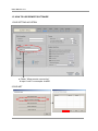
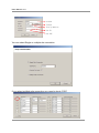

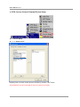

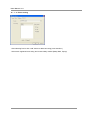
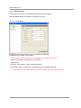


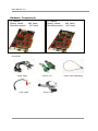
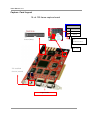
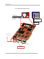
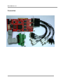
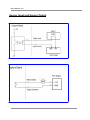

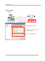
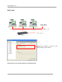
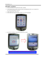
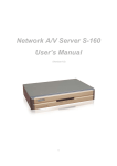
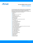
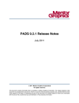
![[Proxyview]User`s Manual (5.1.4.0)](http://vs1.manualzilla.com/store/data/005658349_1-e7f841297d622d23913e7f3fcabf599d-150x150.png)