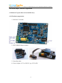
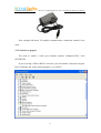
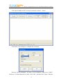
1
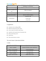
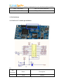
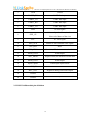
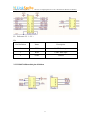
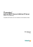
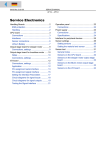
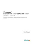
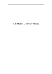
McLaren V2 - High Speed Power Line
Communication Module
User Manual
June,2012
LinkSprite Technologies, Inc
www.linksprite.com
LinkSprite Technologies, Inc.
McLaren V2- High Speed Power Line Communication Module User Manual
McLaren V2- High Speed Power Line
Number
Communication Module User Manual
Version
Doc Title
Version
Date
Description
Author
1.0
07/11/2011
First Version
Nancy
1.1
06/28/2012
Second Version
Nancy
2
1.1
LinkSprite Technologies, Inc.
McLaren V2- High Speed Power Line Communication Module User Manual
Catalogue
The first chapter. Overview............................................................................................ 5
1.1 Product introduction................................................................................................. 5
1.2 Product performance ......................................................................................... 6
1.2.1 AC & DC power line communication ..................................................... 6
1.2.2 Transparent Mode,Plug and use ........................................................... 6
1.2.3 HomePlug1.0 .......................................................................................... 6
1.2.4 5Mbps on power line .............................................................................. 6
1.2.5 FEC ......................................................................................................... 6
1.2.6 OFDM ..................................................................................................... 6
1.2.7 AT commands for high-end set ............................................................... 7
1.2.8 loopback mode ........................................................................................ 7
1.2.9 RoHS-certified ........................................................................................ 7
1.3 Specifications .................................................................................................... 7
1.4 Applications ...................................................................................................... 8
The second chapter. Light and pin definition................................................................. 8
2.1 LED ................................................................................................................... 8
2.2 Pin Definition .................................................................................................... 9
2.2.1 McLaren V2 module pin definition ........................................................ 9
2.2.2 RS232 child module pin definition ....................................................... 10
2.2.3 RS485 child module pin definition ....................................................... 11
The third chapter. AT command set ............................................................................. 13
3.1 Command Mode.............................................................................................. 13
3.1.1 Enter the command mode ..................................................................... 13
3.1.2 Exit command mode ............................................................................. 13
3.2 Parameters and response ................................................................................. 13
3.2.1 Parameters and response ....................................................................... 13
3.2.2 Modify parameters ................................................................................ 13
3.3 Command list .................................................................................................. 14
3
LinkSprite Technologies, Inc.
McLaren V2- High Speed Power Line Communication Module User Manual
3.3.1 Use AT commands attention ................................................................. 15
The fourth chapter. Introduces Application ................................................................. 16
4.1 Mclaren V2 power line carrier module entry .................................................. 16
4.1.1 Hardware preparation............................................................................ 16
4.1.2 Software to prepare ............................................................................... 17
4.1.3 McLaren V2 module communication paradigm ................................... 19
4.2 Operating mode ............................................................................................... 19
4.2.1 Normal mode ........................................................................................ 19
4.2.2 loopback mode ...................................................................................... 20
Contact us..................................................................................................................... 22
4
LinkSprite Technologies, Inc.
McLaren V2- High Speed Power Line Communication Module User Manual
The first chapter. Overview
1.1 Product introduction
This document is to introduce the power line communication module
McLaren V2 , working in 4.3MHz ~ 20.9MHz band. Use OFDM modulation
technology when send data then transmit on the power line. On the receiver side, use
filter to capture the modulation signal and demodulation, you will have the original
signal. So far,McLaren V2can reach a speed of 5Mbps。
McLaren V2 module use Intellon transceiver INT5200for high speed power line
communication modulation and demodulation, to send and recieve data from power
line.
By using OFDM(Orthogal Frequency Division Multiplexing),the module can
better maintain the performance of the modulation signal.
McLaren V2is designed to transmit serial data through the power line,to replace
cable everywhere.
5
LinkSprite Technologies, Inc.
McLaren V2- High Speed Power Line Communication Module User Manual
1.2 Product performance
1.2.1 AC & DC power line communication
McLaren V2can work on 230V/50Hz, 110V/60Hz AC power line,and also on
0-400V DC power line.
1.2.2 Transparent Mode,Plug and use
McLaren V2 support transparent mode,that it only transmit data to the end nodes
but do not care how it is done.It is all about data delivery in Transparent mode.
Users do not have to worry about lower protocols,you can just plug and use,no
other changes on the software side.
1.2.3 HomePlug1.0
McLaren V2 module use INT5200,INT5200 is the first MAC/PHY/AFE power
line transceiver in the world that in HomePlug1.0 Standard,is also the replacement for
INT51X1. McLaren V2 also has ADC,DAC,AGC,filter and power amplifier.
1.2.4 5Mbps on power line
McLaren V2can reach a speed up to 5Mbps on the power line.
1.2.5 FEC
Using FEC data coding technology,fault detection will be verified by the
receiving party.In FEC,the receiving party can not only detect fault,but also where it
happened and correct it.So error correction code is needed in FEC.
1.2.6 OFDM
McLaren V2 use OFDM technology,which is the bases of HPA(HomePlue
Powerline Alliance)Standard,collect different frequency into one signal and transmit.
The advantage of McLaren V2 is that it seperate multiple digital signal and
6
LinkSprite Technologies, Inc.
McLaren V2- High Speed Power Line Communication Module User Manual
transmit around interference signals. Meantime,McLaren V2 monitor any sudden
change on the power line.
1.2.7 AT commands for high-end set
Users can be modified by using the AT command McLaren V2 module system
parameters, such as baud rate, mode, and so on.
1.2.8 loopback mode
McLaren V2 module system can be configured for normal mode and loopback
mode, the output of the data in the normal mode, the module can be received through
the serial port; while in loopback mode, the module will received data is then sent to
the power line, in two communications module, a module is set to loopback mode,
eliminates the need for a serial.
1.2.9 RoHS-certified
McLaren V2 module is RoHS compliant (Restriction of Hazardous Substances).
1.3 Specifications
McLaren V2
Product Name
(Homgplug serial adapter)
3.3V TTL UART
Communication interface
RS232
RS485
230V/50HzAC
Communication power
110V/60Hz AC
line voltage
0-400V DC
Supply voltage
4.5Vto24V DC,typ 12V/2A DC
Signal modulation
OFDM(orthogonal frequency division multiplexing,,
7
LinkSprite Technologies, Inc.
McLaren V2- High Speed Power Line Communication Module User Manual
Homeplug 1.0 compatible)
Error correction coding
FEC(Forward Error Correction Code)
Powerline communication
5Mbps (throughput)
rate
Maximum packet length
300 bytes
Transmission distance
300 feet (without repeaters)
Powerline LED
LED indicator
System LED
Serial LED
1.4 Applications
l
Automatic meter reading (AMR)
l
Industrial manufacturing and control
l
Access control, fire alarm, smoke alarm
l
Acquisition and transmission of instrument data
l
Safety monitoring system
l
Smart Home
l
Solar and wind power systems
The second chapter. Light and pin definition
2.1 LED
LED1(D1 GREEN)
System status lights, idle time flashing (custom)
LED2(D2 RED)
Data flow indicator (can be customized)
LED3(D3 YELLOW)
(Can be customized)
LED4(D4 GREEN)
ACTIVITY LED
LED5(D5 RED)
COLLISION LED
LED6(D6 YELLOW)
LINK STATUS LED
8
LinkSprite Technologies, Inc.
McLaren V2- High Speed Power Line Communication Module User Manual
LED7(D19 RED)
VDD_CPU Power Indicator
LED8(D20 RED)
VDD_1.8DPower Indicator
2.2 Pin Definition
2.2.1 McLaren V2 module pin definition
P2:
Pin
Name
Description
GND
Ground
Definition
1
9
LinkSprite Technologies, Inc.
McLaren V2- High Speed Power Line Communication Module User Manual
2
GND
Ground
3
UART2_RX
UART Data input
4
UART2_TX
UART Data input
5
UART3_RX
UART Data input
6
UART3_TX
UART Data input
7
SDA
IIC data signal
8
SPI3_CS
Master chip select Slave, is select
Slave to be Master of the visit
9
SCL
IIC clock signal
10
SPI3_SCK
Master to Slave transmit clock signal
11
CPU_RST
Reset
12
SPI3_MISO
Data inlet, SPI device receives the data.
13
PWM_OUT2
PWM output
14
SPI3_MOSI
Export of data, the SPI device sends data
15
PWM_OUT1
PWM output
16
Input Capture
PWM input capture mode
17
ASIG_IN
-
18
DAC_OUT
Digital-to-analog conversion output
19
Unused
-
20
Unused
-
2.2.2 RS232 child module pin definition
10
LinkSprite Technologies, Inc.
McLaren V2- High Speed Power Line Communication Module User Manual
P1:Reference 2.2.1(P1)
P2:
Pin Definition
Name
Description
2
TXD
UART Data input
3
RXD
UART Data input
5
GND
Ground
2.2.3 RS485 child module pin definition
11
LinkSprite Technologies, Inc.
McLaren V2- High Speed Power Line Communication Module User Manual
P1:
Pin Definition
Name
Description
1,2
485-B
RS458 D-/B
3,4
485-A
RS485 D+/A
5
PWM
STM32 PWM output
6,7
GND
Ground
8,9
12V
12VPower supply
Pin Definition
Name
Description
1
SDA
IIC data signal
2
WR/R
Read and write data
3
NTX
UART2 data output
P2:
Note: pin1 and pin2 connected for program control; pin2 and pin3 connected to
automatic control; under normal working conditions, the use of self-control control
(pin2 and pin3 link).
P3: reference 2.2.1 (P1)
12
LinkSprite Technologies, Inc.
McLaren V2- High Speed Power Line Communication Module User Manual
The third chapter. AT command set
3.1 Command Mode
3.1.1 Enter the command mode
Through the serial port to send "+ + +" (without the double quotes, plus the Enter
key, behind AT command to add the Enter key) the module into command mode, the
module will reply "Now module running at AT mode!" enter AT command mode. In
order to prevent user data "+ + +" error trigger command mode, the serial port to send
"+ + +" seconds before and after the trigger command mode cannot send and receive
data. Three "+" between the intervals of not more than 1 second, otherwise, they will
be considered as data instead of command.
3.1.2 Exit command mode
Enter the command "ATEX" module will reply "Exited!".
3.2 Parameters and response
3.2.1 Parameters and response
For all the parameters of the command: the parameters of the command with
parameters without parameters. If you do not return to the current settings, with
parameters related parameters set with parameters. Is returned if successfully set OK,
set after the success of the ATSP instructions to save the settings, error if the
command input will return "invalid cmd in!" information.
Command without parameters, the module will revert to the existing
parameters in the module.
3.2.2 Modify parameters
Modify the parameters, in addition to the serial port parameters are immediately
credited to the EEPROM, set after the success of the the ATSP instructions to save the
13
LinkSprite Technologies, Inc.
McLaren V2- High Speed Power Line Communication Module User Manual
settings and take effect immediately.
After the revision of the serial port parameters, will not immediately take
effect, to prevent users must also be followed to modify the PC serial port parameters
can continue to enter commands. Set up after the success of the serial port parameters
to use the ATSP instructions to save the settings and exit command mode, automatic
restart module to take effect.
3.3 Command list
AT command list:
Instructio
n
ATDA
ATSA
Function
Query destination
address
Query the source
address
Param
Without reference return
eters
Reference
sample
N
FF-FF-FF-FF-FF-FF
N
N
00-22-6C-01-00-01
N
ATBD
Set baud rate
Y
9600
ATBD 9600
ATDB
Set bit of data
Y
8
ATDB 8
Y
N
ATPA N
Y
1
ATLP 1
Set the parity
ATPA
bit
ATLP
ATMA
ATRS
ATEX
Set stop bit
Return module
information
Reset system
Exit the AT
command
LinkSprite's
N
High_Speed_PLC_mode
N
m
N
The system will reset!
N
N
Exited!
N
14
LinkSprite Technologies, Inc.
ATLB
McLaren V2- High Speed Power Line Communication Module User Manual
Set the loopback
Save settings
ATLB Y
NO
ATLB N
Y
mode
ATSP
YES
Parameter save ok! The
N
system will reset!
N
3.3.1 Use AT commands attention
1) instruction parameters with parameters, without parameters, with no
parameters returns the current settings, with parameters relevant parameter settings,
setting success is returned OK to use the the ATSP instructions to save the settings set
successfully, If the command input error will return "invalid cmd!" information.
2) the back of the module affixed to the product of the source address (MAC
address), the destination address is the unified configuration of FF-FF-FF-FF-FF-FF,
is a broadcast address.
3) after power module will output "LinkSprite's High_Speed_PLC_modem"
These product information, go to the normal data transmission working condition.
4) These systems provide 1200,2400,4800,9600,19200,38400,115200 baud rate
can be set, the system provides a maximum baud rate of 115200, available AT
commands to system settings.
5) The system can be configured for normal mode and loopback mode, the
output of the data in the normal mode, the module can be received through the serial
port; while in loopback mode, the module will received data is then sent to the power
line, in two modules communications module set to loopback mode, eliminates the
need for a serial.
15
LinkSprite Technologies, Inc.
McLaren V2- High Speed Power Line Communication Module User Manual
The fourth chapter. Introduces Application
4.1 Mclaren V2 power line carrier module entry
4.1.1 Hardware preparation
1)McLaren V2 module
2)RS232/RS485 adapter module
3)Powerline cable
4)Power Adapter: 4.5V to 24V DC, typ 12V/2A DC
16
LinkSprite Technologies, Inc.
McLaren V2- High Speed Power Line Communication Module User Manual
Note: multiple McLaren V2 module communication, connection method is the
same.
4.1.2 Software to prepare
You need to install a serial port terminal software LinkSprite-NEC, click
SETUP.EXE.
If you are using a USB or RS232 converter, you can find the COM port using the
Device Manager tab. In the following figure, it is COM17.
17
LinkSprite Technologies, Inc.
McLaren V2- High Speed Power Line Communication Module User Manual
Click Open LinkSprite-NEC serial port terminal, as shown
below:
Click on the "port settings" to configure the serial port:
From the "Device Manager", we know, we are using the COM port is COM17.
McLaren V2 default baud rate of 9600. Click "OK", and then click "Open COM port
18
LinkSprite Technologies, Inc.
McLaren V2- High Speed Power Line Communication Module User Manual
to open COM port.
4.1.3 McLaren V2 module communication paradigm
Power line
McLaren
V2
McLaren
V2
McLaren
V2
McLaren
V2
McLaren
V2
McLaren
V2
McLaren V2
Note: multiple McLaren V2 module communication, each McLaren V2 need to
set the same baud rate and connected to a power line.
4.2 Operating mode
4.2.1 Normal mode
In the normal mode, the module can be received through the serial data output.
Power line transparent transmission
McLaren V2-A
Ordinary work
mode
McLaren V2-B
Ordinary work
mode
19
LinkSprite Technologies, Inc.
McLaren V2
V2- High Speed Power Line Communication Module User Manual
McLaren V2-A send data:
McLaren V2-B
B receives the data:
4.2.2 loopback mode
In loopback mode, the module will received data is then sent to the power line, in
the case of two modules communicate, a module is set to loopback mode, eliminates
the need for a serial.
Power line transparent transmission
McLaren V2-A
Ordinary
work
mode
McLaren V2-B
B
loopback mode
McLaren V2-A
A when transmitting data through the transparent transmission of
power line, McLaren V2-B
B can receive data and the received data and then send back
20
LinkSprite Technologies, Inc.
McLaren V2- High Speed Power Line Communication Module User Manual
to the power line to this case McLaren V2-A can receive returned McLaren V2-Bdata
seen McLaren V2-A and McLaren V2-B communication success. So that through a
serial port can be seen McLaren V2 data transmission situation.
McLaren V2-A to send data and receive return data:
21
LinkSprite Technologies, Inc.
McLaren V2- High Speed Power Line Communication Module User Manual
Contact us
LinkSprite Technologies, Inc.
USA Office:
Address: 1067 S Hover St, Unit E-186,Longmont, CO 80501,USA
Voice: +1-7202790774 (USA)
China Office:
Address:Building E3, Suite 1101, Optics Valley Software Park,Wuhan, Hubei, china
Voice: +86-27-87608172(China)
Support Ticket System: www.linksprite.com/support/
Support: [email protected]
Sales: [email protected]
Website: www.linksprite.com, www.linksprite.cn
22