1
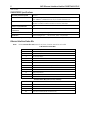
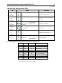
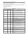
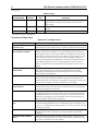
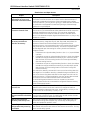
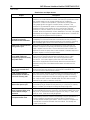
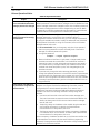
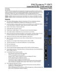
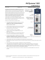
PACSystems* RX3i IC695ETM001-FS GFK-2332R August 2014 Ethernet Interface Module The Ethernet Interface Module, IC695ETM001, connects a PACSystems RX3i controller to an Ethernet network. It enables the RX3i controller to communicate with other PACSystems equipment and with Series 90 and VersaMax controllers. The Ethernet Interface provides Transmission Control Protocol and Internet Protocol (TCP/IP) communications with other control systems, host computers running the Host Communications Toolkit or programmer software, and computers running the TCP/IP version of the programming software. These communications use the Service Request Transport Protocol (SRTP), Modbus TCP, and Ethernet Global Data (EGD) protocols over a four-layer TCP/IP (Internet) stack. Features of the RX3i Ethernet Interface include: ▪ Full programming and configuration services. Firmware upgrades from the RX3i CPU using the WinLoader software utility, which is supplied with updates to the Ethernet Interface software. ▪ ▪ Periodic data exchange using Ethernet Global Data (EGD). ▪ ▪ TCP/IP communication services using SRTP. ▪ Built-in Station Manager for on-line supervisory access to the Ethernet Interface. Dedicated Station Manager port. ▪ Two auto-sensing 10Base T / 100Base TX RJ-45 shielded twisted-pair Ethernet ports for direct connection to either a 10BaseT or 100BaseTX IEEE 802.3 network without an external transceiver. There is only one interface to the network (only one Ethernet MAC address and only one IP address). ▪ ▪ Internal network switch with Auto negotiate, Sense, Speed, and crossover detection. EGD Commands to read and write controller and EGD exchange memory over the network. Support for SRTP Channels, Modbus/TCP Server, and Modbus/TCP Client Recessed Ethernet Restart pushbutton permits manually restarting the Ethernet firmware without power cycling the system. ▪ ▪ LEDs: Ethernet OK, LAN OK, Log Empty, individual port activity and speed LEDs. ▪ Time synchronization to SNTP Time Server on Ethernet network (when used with Release 5.00 or later CPU module). Configurable stand-alone Redundant IP addressing, which allows a single IP address to be assigned to corresponding Ethernet modules in two different controllers. The Redundant IP address is configured in addition to the normal unique IP address of each Ethernet module. Under application logic control, only the Ethernet module in the active unit can use the Redundant IP address. * Indicates a trademark of General Electric Company and/or its subsidiaries. All other trademarks are the property of their respective owners. Copyright © 2013-2014 by General Electric Company. All Rights Reserved 2 RX3i Ethernet Interface Module IC695ETM001-FS IPI GFK-2332R IC695ETM001 Specifications Ethernet processor speed 200 MHz Connectors - Station Manager (RS-232) Port: 9-pin female D-connector - Two 10BaseT / 100BaseTX Ports: 8-pin female shielded RJ-45 LAN IEEE 802.2 Logical Link Control Class I IEEE 802.3 CSMA/CD Medium Access Control 10/100 Mbps Number of IP addresses One Number of Ethernet Port Connectors Two. both are 10BaseT / 100BaseTX with auto-sensing RJ-45 connection. Embedded Ethernet Switch Yes – Allows daisy-chaining of Ethernet nodes. Serial Port Station Manager Port: RS-232 DCE, 1200 – 115,200 bps. Refer to the PACSystems RX3i System Manual, GFK-2314, for product standards and general specifications. Ethernet Interface Status Bits Note: Unless LAN Interface OK (Status Bit 16) is set, the other status bits are invalid. LAN Interface Status Bits 1 Port 1A full duplex 2 Port 1A 100Mbps 3 Port 1B full duplex 4 Port 1B 100 Mbps 5 Network Time Locked 6 Redundant IP address is active 7-8 9 10–12 Reserved Any Channel Error (error on any channel) Reserved 13 LAN OK 14 Resource problem 15 Module Overtemperature 16 LAN Interface OK Channel Status Bits (Two for each channel) 17 Channel 1 Status (SRTP: Data Transfer) 18 Channel 1 Status (SRTP: Channel Error) ... ... 79 Channel 32 Status (SRTP: Data Transfer) 80 Channel 32 Status (SRTP: Channel Error) RX3i Ethernet Interface Module IC695ETM001-FS IPI 3 GFK-2332R Indicator Light Emitting Diodes (LEDs) State LED Indicates ETHERNET OK LAN OK LOG EMPTY Fast Blink Off Off Performing Diagnostics ETHERNET OK LAN OK LOG EMPTY Slow Blink Off Off Waiting for Ethernet configuration from CPU ETHERNET OK LAN OK LOG EMPTY Slow Blink† On/Traffic/Off Slow Blink† ETHERNET OK LAN OK LOG EMPTY On On/Traffic/Off On/Off Operational ETHERNET OK LAN OK LOG EMPTY Blink error code Off Off Hardware failure. See chapter 11 for blink code definitions. ETHERNET OK LAN OK LOG EMPTY Slow Blink† Slow Blink† Slow Blink† († EOK and STAT blink in unison) Waiting for IP Address († All LEDs blink in unison; pattern same while awaiting or performing load) Firmware Update Field Wiring Station Manager (RS-232) Port Pin Assignment Pin No Signal Direction Description 1† DCD IN 2 TX OUT Transmit Data 3 RX IN Receive Data 4 DSR IN Data Set Ready 5 GND 6 DTR OUT 7 CTS IN Clear to Send 8 RTS OUT Ready to Send 9 RI IN Ring Indicator Data Carrier Detect Signal Ground Data Terminal Ready † Pin 1 is at the bottom right of the Station Manager port connector as viewed from the front of the module. 4 RX3i Ethernet Interface Module IC695ETM001-FS IPI GFK-2332R Hardware Installation Initial Checks Upon receiving your RX3i equipment, carefully inspect all shipping containers for damage. If any part of the system is damaged, notify the carrier immediately. The damaged shipping container should be saved as evidence for inspection by the carrier. As the consignee, it is your responsibility to register a claim with the carrier for damage incurred during shipment. GE Intelligent Platforms will fully cooperate with you, however, should such action be necessary. After unpacking the RX3i equipment, record all serial numbers. Serial numbers are required if you should need to contact Customer Care during the warranty period. All shipping containers and all packing material should be saved should it be necessary to transport or ship any part of the system. Verify that all components of the system have been received and that they agree with your order. If the system received does not agree with your order, contact Customer Care. Installation Location This product is intended for use with the RX3i system. Its components are considered open equipment (having live electrical parts that may be accessible to users) and must be installed in an ultimate enclosure that is manufactured to provide safety. As a minimum, the enclosure shall provide a degree of protection against solid objects as small as 12mm (e.g. fingers). This equates to a NEMA/UL Type 1 enclosure or an IEC60529 IP20 rating providing at least a pollution degree 2 environment. For details about installing RX3i rack systems, refer to GFK 2314. If you need technical help, contact Technical Support. For phone numbers and email addresses, see the back cover of this Guide. Installation in Hazardous Areas The following information is for products bearing the UL marking for Hazardous Areas or ATEX marking for explosive atmospheres: CLASS 1 DIVISION 2 GROUPS ABCD • This equipment is an open-type device and is meant to be installed in an enclosure suitable for the environment that is only accessible with the use of a tool. • Suitable for use in Class I, Division 2, Groups A, B, C and D Hazardous Locations, or nonhazardous locations only. • Warning – EXPLOSION HAZARD - SUBSTITUTION OF COMPONENTS MAY IMPAIR SUITABILITY FOR CLASS I, DIVISION 2. • Warning – WHEN IN HAZARDOUS LOCATIONS, TURN OFF POWER BEFORE REPLACING OR WIRING MODULES; AND • Warning – DO NOT CONNECT OR DISCONNECT EQUIPMENT UNLESS POWER HAS BEEN SWITCHED OFF OR THE AREA IS KNOWN TO BE NONHAZARDOUS. • Warning – EXPLOSION HAZARD - USB PORT IS ONLY FOR USE IN NONHAZARDOUS LOCATIONS, DO NOT USE UNLESS AREA IS KNOWN TO BE NON-HAZARDOUS. ATEX Zone 2 This product must be mounted in an enclosure certified in accordance with EN60079-15 for use in Zone 2, Group IIC and rated IP54. The enclosure shall only be able to be opened with the use of a tool. RX3i Ethernet Interface Module IC695ETM001-FS IPI 5 GFK-2332R Module Installation The ETM001 must be installed in the main (CPU) rack of an RX3i system, using a Universal Backplane such as IC695CHS007, CHS012 or CHS016. The ETM001 supports insertion/removal while power is applied to the system (hot swap). This module is compatible with all RX3i CPU models. 1. RX3i rack power may be off or on (“hot insertion”). 2. Holding the module firmly, align the module with the correct slot and connector, then swing the module down until the module’s connector engages the backplane’s backplane connector. Visually inspect the module to be sure it is properly seated. 3. Insert the two provided M3x5mm machine screws through the module’s bottom bracket into threaded holes in the bottom of the backplate and screw them several turns using a #1 Phillips screwdriver. Tighten to 0.7 N-m (6 in-lbs). Related Documents For additional information about the Ethernet Interface Module, refer to the following publications: GFK-2314, PACSystems RX3i System Manual GFK-2224, TCP/IP Ethernet Communications for PACSystems GFK-2225, PACSystems TCP/IP Communications, Station Manager Manual Additional Support For support and information, visit GE Intelligent Platforms’ website at http://www.ge-ip.com. The files for this manual and other related documentation are available there. Additional region- and language-specific websites and telephone numbers are found there as well. 6 RX3i Ethernet Interface Module IC695ETM001-FS IPI GFK-2332R Important Product Information for this Release This release of the product is a hardware-only upgrade which replaces the module’s plastic housing with a metal case, which improves noise immunity, reduces emissions, and increases the mechanical robustness of the product. There is no change to the module’s firmware and no change to any functionality. Important Note: It is recommended that the user change the station manager password to a password other than the default password. Access to Remote Station Manager will be disabled when the station manager password is set to the default password. Updates The IC695ETM001 is field upgradeable using the firmware upgrade utility. To upgrade an existing ETM001 to firmware version 6.21, you will need the upgrade kit 44A753032-G15, which can be downloaded from http://www.ge-ip.com/support. The hardware cannot be upgraded in the field. Functional Compatibility Functional Compatibility Subject Description Hot Swap requires CPU firmware 2.51 Do not remove or insert the IC695ETM001 while powered unless the CPU is running firmware release 2.51 or higher. This firmware is available in upgrade kit 44A7522290-G01. SRTP and EGD performance differs from Series 90*-30 SRTP and EGD performance in the RX3i differs slightly from the Series 90-30. Each RX3i Ethernet Interface supports a greater number of SRTP connections and EGD exchanges. The RX3i currently has several SRTP and EGD operational restrictions compared to the Series 90-30. When migrating Series 90-30 Ethernet applications to the RX3i, please carefully read the Ethernet Operational Notes. Series 90-30 LAN Interface module (IC693CMM321) not supported by RX3i The Series 90-30 LAN Interface Module (IC693CMM321) is not supported by the RX3i and should not be placed in an RX3i rack. (Series 90-30 CPUs with embedded LAN Interface, IC693CPU364 and IC693CPU374, like any Series 90-30 CPU, should not be placed in an RX3i rack.) Modbus/TCP support Release 3.60 of the PACSystems Ethernet Interface adds Modbus/TCP Client Channels capability. It supports Modbus Conformance Class 0 function codes 3 and 16, Conformance Class 1 function codes 1, 2, 4, 5, 6, and 7, and Conformance Class 2 function codes 15, 22, 23, and 24. PACSystems Ethernet supports 32 client connections shared between all client protocols. For example, if 16 client connections are used for SRTP channels, there are 16 client connections available for Modbus/TCP channels. Any given channel can be assigned to only one protocol at a time. Programmer version requirements Proficy* Machine Edition Logic Developer 5.8 or later must be used to perform Run-mode Store of EGD exchanges. Proficy Machine Edition Logic Developer 5.7 or later must be used for Release 5.00 new features. Proficy Machine Edition Logic Developer 5.5 Service Pack 2 or later must be used for Release 4.00 new features. Proficy Machine Edition Logic Developer 5.0 Service Pack 3 or later must be used to program the RX3i CPU for Modbus/TCP Server operation. CIMPLICITY* Plant Edition version requirements CIMPLICITY Plant Edition 6.1 Service Pack 1a with Update 040204_s90tcp_6101 or Service Pack 2 or later must be used for Ethernet communications with PACSystems. RX3i Ethernet Interface Module IC695ETM001-FS IPI 7 GFK-2332R New Features and Enhancements in This Release This release of the product is a hardware-only upgrade which replaces the module’s plastic housing with a metal case, which improves noise immunity, reduces emissions, and increases the mechanical robustness of the product. Problems Resolved by This Release No problems are resolved in this product release. Release History Release History Firmware Version Date IC695ETM001-FS 6.21 Aug. 2014 Replaces the module’s plastic housing with a metal case, improving noise immunity, reducing emissions, and increasing the mechanical robustness of the product. No change to the module’s firmware or functionality. IC695ETM001-ES† 6.21 Jan. 2014 Ethernet Firmware version fixes an issue with calculating DST correction in the European Union when SNTP is enabled. IC695ETM001-ER 6.20 Jul. 2013 Adds support in SNTP for local time zones and daylight savings time and resolves the field issues described on page 7. IC695ETM001-EP† 6.14 Jul. 2012 Resolves an issue with a spurious blink code being displayed during SRTP communications with CIMPLICITY Plant Edition software. IC695ETM001-EN 6.13 Apr. 2012 Addresses a field issue and a product security issue. For details, refer to GFK-2332M. IC695ETM001-EM 6.12 Dec. 2011 Disables several unnecessary services in the firmware that otherwise could result in disruption of system operation and/or data corruption. For details, refer to GFK-2332L. IC695ETM001-EL† 6.11 Nov. 2011 Resolves an issue with missed EGD samples. For details, refer to GFK-2332K. IC695ETM001-EK 6.10 Sep. 2011 For problems resolved, refer to GFK-2332J. IC695ETM001-EJ 6.00 Sep. 2009 Adds an SRTP inactivity timeout for better recovery from lost communication with the programmer. For details and problems resolved, refer to GFK-2332H. IC695ETM001-EH 5.51 Jan. 2009 Adds new diagnostics capabilities. For details and problems resolved, refer to GFK-2332G. Hardware version Ex updates the IC695ETM001 for RoHS compliance. IC695ETM001-DG 5.50 May 2008 Adds ability to modify produced and consumed EGD exchanges during run mode store. For problems resolved, refer to GFK-2332F. IC695ETM001-DF 5.01 Dec. 2007 For problems resolved, see GFK-2332E. IC695ETM001-DE 5.00 Aug. 2007 Hardware changes to improve performance during hot swaps. For additional new features and problems resolved, refer to GFK-2332D. IC695ETM001-CD 3.81 May 2006 Added support for eight Ethernet interfaces in the RX3i main backplane. For details and problems resolved, refer to GFK-2332C. Catalog Number Comments 8 RX3i Ethernet Interface Module IC695ETM001-FS IPI GFK-2332R Release History Firmware Version Date Comments IC695ETM001-CC 3.60 Nov. 2005 Added support for Modbus/TCP client and Ethernet plug-in applications. For details and problems resolved, refer to GFK-2332B. IC695ETM001-AB 3.00 Apr. 2005 For new features and problems resolved, refer to GFK2332A. IC695ETM001-AA 2.51 Aug 2004 Initial release Catalog Number † Available only as an upgrade kit. Restrictions and Open Issues Restrictions and Open Issues Subject Description Number of SRTP requests tallied may vary When running multiple SRTP client channels, the number of requests, as reported by the client and the server, may differ between the connections. SRTP connections remain open after IP address changed The Ethernet Interface does not terminate all open SRTP connections before changing its IP address. If the local IP address has changed, any existing open TCP connections are unable to normally terminate. This can leave SRTP connections open until their underlying TCP connections time out. If quicker recovery of the SRTP connection is needed, modify the “wkal_idle” Advanced User Parameter to reduce the TCP keep-alive timer to the desired maximum time for holding open the broken connection. Refer to TCP/IP Ethernet Communications for PACSystems, GFK-2224, for details. REPP does not save results of aborted PING The Station Manager REPP command does not retain the results of a PING that is aborted due to error. Results are reported when the PING is aborted, but subsequent REPP commands give the results of the last successfully terminated PING. Multiple log events The Ethernet Interface sometimes generates multiple exception log events and Controller Fault Table entries when a single error condition occurs. Under repetitive error conditions, the exception log and/or Controller Fault Table can be completely filled with repetitive error messages. Intermittent SNTP loss of synchronization Under moderately heavy EGD traffic load, the Ethernet Interface may occasionally lose synchronization with its SNTP time server and generate exception log event 29, entry 2=bH. SRTP communication delays Average latency of communications on SRTP channels may vary considerably due to TCP retransmissions. SRTP client applications should be designed to take this variance into account. In particular, SRTP client applications migrating from Series 90 SRTP servers to PACSystems may need to lengthen SRTP timeout parameters. Spurious ‘Ethernet Failure’ error On rare occasions, the error “Module hardware fault” may be reported on the Ethernet daughterboard. The corresponding fault in the exception log is Event = 1, followed by text "Ethernet failure". This fault is a nuisance fault and may be ignored. Spurious Ethernet fault In rare instances, after power cycle, the Ethernet Interface may log the following fault, Event = 28H, Entry 2 = 000eH. This fault can be safely ignored. Unexpected EGD COMMREQ status EGD Commands may return COMMREQ Status 9590H (= internal error) instead of the expected B190H (= Can’t locate remote node) when unable to locate a remote device on the network. RX3i Ethernet Interface Module IC695ETM001-FS IPI 9 GFK-2332R Restrictions and Open Issues Subject Description Very heavy EGD production/ consumption at server may cause EGD command timeouts Very heavy EGD production and/or consumption at a server device may cause EGD command timeout errors when another device attempts to send EGD commands to that server. If EGD commands must preempt normal production, you may set the “gcmd_pri” Advanced User Parameter to 2 (see GFK-2224, Appendix A). Note that by doing so, EGD exchange production may be delayed. SRTP server errors can cause timeouts at channel client The SRTP Server in the PACSystems Ethernet Interface can encounter various errors if a remote Series 90 client takes down an SRTP connection and then establishes a new connection. This can cause unexpected channel timeout errors 0190H or 0290H at the client. The SRTP server errors in the Ethernet exception log are identified as Event = 2; Entry 2 may be 001cH, or 0021H. When an EGD Command attempts a write operation to a bit-mode reference memory range (%I, %Q; %T, %M, %SA, %SB, %SC) where the amount of data to be written exceeds the configured size of that reference memory, the command will return failure status but partial data may be written into the reference memory. The amount of partial data written depends upon the starting bit memory location and the data length as follows: ▪ If data starts on a byte boundary (location = (8 n) + 1), no partial data is written. ▪ If data does not start on a byte boundary (location = (8n)+1) and data exceeds the configured reference memory by 8 or more bits, partial data is written from the starting location to the next byte boundary after the starting location. ▪ If data does not start on a byte boundary (location = (8n)+1) and data exceeds the configured reference memory by less than 8 bits, partial data is written from the stating location to the end of configured reference memory. For a Write PLC Memory command, this can occur when writing data into the target PLC. For Read PLC Memory or Read Exchange commands, this can occur when writing data received from the target controller into the local CPU memory. The logic application must not use any data returned to the local CPU if the EGD command status indicates failure. To avoid writing partial data to the local or remote PLC, be sure bit memory data transfers do not exceed the configured reference memory sizes at the appropriate PLC. EGD command range failure can write partial data to controller bit memory Do not operate with CPU in incorrect slot The operation of the Ethernet interface is disrupted if the RX3i CPU is placed in a slot other than the one in which it is configured. Various Ethernet exception log events may occur, such as (Entry = 2, Entry 2 = 30 or 35 or 39 or 1e or 1f) or (Entry = 8, Entry 2 = b). No CPU fault logged when Ethernet interface in fatal blink code The CPU does not log any Controller or I/O Faults when the Ethernet Interface has a fatal blink code. The application should monitor the LAN interface OK status bit to detect loss of module. EGD I/O has unexpected variability under heavy load EGD I/O has intermittent unexpected variability under heavy load. For a Produced Exchange, EGD samples may occasionally be delayed by as much as a production period or more. Clear of large hardware configurations may cause log event 08/20 A Log event 08/20 may occur when very large hardware configurations are cleared and transfers are active on other Server connections. This log event can be safely ignored. 10 RX3i Ethernet Interface Module IC695ETM001-FS IPI GFK-2332R Restrictions and Open Issues Subject Description Reset pushbutton Reset pushbutton action is different from other PACSystems Ethernet products. On the RX3i Ethernet module, the state of the pushbutton when the module powers up can change the behavior of the Restart pushbutton. Under normal operation, a pushbutton press produces a rising-edge signal that triggers a module restart. However, if the pushbutton is pressed when power is activated (either by pressing the pushbutton before turning power on or by continuing to hold the pushbutton in after a restart), the functionality of the pushbutton is inverted. When the pushbutton is later released, an "incorrect" rising-edge is detected, which triggers an inappropriate module restart. This does not occur on other PACSystems Ethernet products. COMMREQ Status Word value of 0x54A0 occasionally returned for EGD commands Occasionally a COMMREQ Status Word value of 0x54A0 is returned after COMMREQs for Ethernet Global Data commands when the previouslytransferred command has experienced retries in the network. Executing the COMMREQ again results in successful transfer of the command. Modbus/TCP channel aborted during power-cycle After powering up an RX3i running Modbus/TCP client channels, the establish connection occasionally fails because the server rejects the "open" request from the client. The connection will then succeed if the application retries the open when it sees a 0x9690 or 0xAA90 response to an open request or to the first write request. Controller response timeout errors (8/08) in Ethernet exception log under extremely heavy SRTP traffic Under extremely heavy SRTP traffic conditions, the Ethernet Interface may log an event in the Ethernet exception log (Event 8, Entry 2 = 08H) indicating an overload condition. This error terminates the SRTP connection. If this event appears, either the traffic load should be reduced, or the application should use an alternate communications method to verify that critical data transfers were not lost due to the overload. SRTP channel transfers may take up to 20 seconds after power cycle When SRTP communications are interrupted by a power cycle, the Ethernet interface may require up to 20 seconds to reestablish TCP connection used for SRTP communications. "rmdir" Station Manager command does not work for multi-level directory path The "rmdir" Station Manager command does not operate properly with a multi-level directory path. Instead, first change to the parent directory, then delete the target directory without specifying a path. For example, the "rmdir dir1/dir2" results in "RMDIR Failed, dir1/dir2 does not exist". Instead, first do "cd dir1" and then "rmdir dir2". Intermittent Ethernet log event 8H/15H after power cycle When starting after a power cycle, the Ethernet Interface may intermittently log an exception (entry 8H, Entry 2 = 15H, Entry 3 = 0000H, Entry 4 = 00aaH). This exception is benign and may be ignored. Intermittent Modbus/TCP Server log events when using "killms" Station Manager command When using the "killms" Station Manager command to manually terminate an active Modbus/TCP server connection, the following Modbus/TCP errors may occur in the Ethernet exception log: Event 2fH, Entry 2 = 209H, 212H, 21bH, or 221H. These errors may be ignored. Module intermittently unresponsive after reset Intermittently, when the module is restarted by using the pushbutton or Station Manager command, the module will blink its OK LED for 5 minutes before completing the restart. After the restart is complete the module fails to communicate with the CPU module. The remedy is to power-cycle the PLC. RX3i Ethernet Interface Module IC695ETM001-FS IPI 11 GFK-2332R Restrictions and Open Issues Subject Description A890 Commreq status after multiple Modbus open command attempts When using a Commreq to open a Modbus/TCP Channel to a remote server, if the initial Commreq returned an AA90 status, then future Open Commands may return A890 status. This indicates that local networking resources have been consumed and are not available for further connection attempts. If this occurs, the application must wait at least 60 seconds before making the next connection attempt. This will allow networking resources to be released and made available for the next Modbus Open Command. Modbus/TCP request packets The Modbus/TCP server expects to receive each Modbus/TCP request in a separate TCP packet. If multiple requests are sent in a single packet, the server may or may not send a response to each request. If responses are sent to the client, they will be sent in separate TCP packets. EGD production delayed after RMS of EGD When a produced EGD exchange is added or modified by a Run-mode Store, the exchange will not be produced until one production period of time has elapsed after the completion of the run-mode store. Station Manager PING commands When initiating ICMP echo requests from the PLC via the Station Manager’s PING command, the operation occasionally fails and an exception is logged (Event eH, Entry 2 = 6H). Station Manager “referr” tally The EGD Station Manager “referr” tally may be incremented twice when an exchange timeout occurs. Exchange status word reporting works correctly and is not affected. “wkal_idle” AUP parameter should not allow zero Zero is allowed for the “wkal_idle” (TCP keepalive timer) but it is an invalid value. TCP connection may timeout early if the timeout is set greater than 10 minutes If the TCP connection timeout is set higher than 10 minutes, the connection may timeout before the configured value. The connection timeout is derived from three AUP parameters: wkal_idle + (wkal_cnt + 1) wkal_intvl. 12 RX3i Ethernet Interface Module IC695ETM001-FS IPI GFK-2332R Ethernet Operational Notes Ethernet Operational Notes Subject Description Remote Station Manager access is disabled until Station manager password is changed User should change the station manager password to other than the default password. The remote station manager access is disabled until the station manager password is changed to other than the default password. The station manager password can be changed using an AUP file. (Refer to Appendix A, Configuring Advanced User Parameters in TCP/IP Ethernet Communications for PACSystems User’s Manual, GFK-2224K.) Changing the default Station Manager password is strongly recommended GE Intelligent Platforms strongly recommends that you change the Station Manager password to a value other than the default. Before a configuration has been stored to the CPU, you can change the password by using the CHPARM command to modify the Advanced User parameter (AUP) stpasswd. For details on using this command, refer to the Station Manager Manual, GFK-2225. It is not recommended that you change any AUP other than stpasswd. 1. Use the current password to access the Modify level of the Station Manager. The default password is system. 2. Change the password. Example: = chparm stpasswd newpass 3. Restart the Ethernet interface or cycle power. Changes made via the CHPARM command do not take effect until the Ethernet interface is restarted or power is cycled. Advanced User Parameters are saved in non-volatile memory. Changes made by the CHPARM command are retained over restart and power cycles, until changed again by the CHPARM command. 4. To permanently change the Station Manager password, you must change the stpasswd parameter in the AUP file. See the TCP/IP Ethernet Communications for PACSystems User’s Manual, GFK-2224 for details. (After the CPU configuration has been stored into the CPU, the CHPARM command is prohibited and any previous changes made with it are no longer effective.) Configuration of IP Address is required before using Ethernet communications The Ethernet Interface cannot operate on a network until a valid IP address is configured. The Ethernet addressing information must be configured prior to actual network operation, or to recover from inadvertent changes to the Ethernet addressing data at the Ethernet Interface. Use one of the following methods to initially assign an IP address: Connect a serial terminal to the Interface’s Station Manager port. Then use the CHSOSW command to enter the desired IP address. For details, see PACSystems TCP/IP Communications Station Manager Manual, GFK-2225. Temporarily assign an IP address to the module using the SetIP tool over the Ethernet network. For details, see TCP/IP Ethernet Communications for PACSystems, GFK-2224. The Ethernet Interface automatically obtains a temporary IP Address from a BOOTP server on the network. For details, see TCP/IP Ethernet Communications for PACSystems, GFK-2224. Once a temporary IP address has been set up, the Ethernet Interface can be accessed over the network (by the Machine Edition programming software). The programmer should then be used to configure the proper IP address for the Ethernet Interface. RX3i Ethernet Interface Module IC695ETM001-FS IPI 13 GFK-2332R Ethernet Operational Notes Subject Description Default IP address (0.0.0.0) attempts to set IP address via BOOTP The default IP address value (0.0.0.0), whether obtained from HW Configuration or backup configuration, causes the Ethernet Interface to request a temporary IP address from a BOOTP server device on the network. LAN must be tree, not ring The two Ethernet network ports on the PACSystems RX3i Ethernet Interface must not be connected, directly or indirectly, to the same network device. The hub or switch connections in an Ethernet network must form a tree and not a ring; otherwise duplication of packets and network overload may result. In this situation, the RX3i Ethernet modules will continually reset. Reporting of duplicate IP address The PACSystems RX3i does not log an exception or a fault in the Controller Fault Table when it detects a duplicate IP address on the network. Multiple zero period EGD exchanges may not produce similar numbers of samples If more than one EGD produced exchange is configured for a production period of zero, the exchanges may not produce similar numbers of samples. Due to the way that scheduling occurs when multiple exchanges are scheduled “as fast as possible”, some zero period exchanges may produce significantly more samples than others. For more consistent EGD production, configure the produced EGD exchanges with non-zero production periods. Changing IP address while SRTP connection open may generate log events Open SRTP Server connections established with a remote SRTP client are not terminated as expected when the RX7i’s IP address is changed (typically by storing a new HW Configuration to the RX7i). A Series 90 SRTP client (“SRTP channels”) reports either a 9690H or 0190H status; the SRTP connection may remain open until the connection is terminated as a result of a client timeout. Please refer to Open Ethernet Problems, Internal Problem ID Code CR-1434 for more information. Series 90-30 datagram restrictions Series 90-30 – format datagrams are supported, but cannot access %P or %L memory. Advanced User Parameter wsnd_buf should not be changed The Advanced User Parameter “wsnd_buf” should not be changed. Changing this value may cause the LAN LED to go out and the Ethernet Interface to drop connection. Heavy load can block Station Manager As explained in PACSystems TCP/IP Station Manager Manual, GFK-2225, Chapter 1, a heavy EGD and/or SRTP load can block Station Manager operation. One-time delay of EGD Production (and possibly Consumption) if more than 24 SRTP Server connections are started simultaneously If more than 24 SRTP Server connections are established simultaneously, EGD Production may be briefly delayed for each connection after the 24th when the connections are first made after power is applied. If EGD consume acceleration has been disabled, then EGD Consumption is also delayed. The delay only occurs once when the SRTP Server connection is established for the first time after Powerup. No delay is experienced for the first 24 SRTP Server connections. Very heavy EGD production/consumption at server may cause EGD command timeouts Very heavy EGD production and/or consumption at a server device may cause EGD command timeout errors when another device attempts to send EGD commands to that server. If EGD commands must preempt normal production, you may set the “gcmd_pri” Advanced User Parameter to 2 (see GFK-2224, Appendix A). Note that by doing so, EGD exchange production may be delayed. 14 RX3i Ethernet Interface Module IC695ETM001-FS IPI GFK-2332R Ethernet Operational Notes Subject Description SRTP Application Timeouts must accommodate network connection overhead The application timeouts within SRTP Channels also include the time needed to establish and maintain the underlying network and STRP connection. Examples are establishing the TCP connection for a new channel, establishing communication with the remote device, and TCP retransmissions during Channel operations. If the time needed for TCP connection establishment or maintenance exceeds the user-specified channel application timeout values, an application timeout will occur. Channel application timeouts are temporary errors; the channel continues to run. Client Channels and Redundant IP In a Redundancy System, Client Channel COMMREQs can only be initiated from the unit that owns the Redundant IP address. Therefore, the user application logic should use Bit 6 in the LAN Interface Status bit area, “Redundant IP Active” as part of their enabling logic that drives a client channel COMMREQ. Idle Modbus/TCP connection between a Series 90 and a PACSystems may be prematurely terminated An idle Modbus/TCP connection between a Series 90 controller and the PACSystems Ethernet Interface may be prematurely terminated. There is an incompatibility between the TCP "Keep-Alive" timer values on the PACSystems Ethernet Interfaces and Series 90 Ethernet Interfaces. The default value of the keep-alive timer for the Series 90 modules is set to a much higher value than for the PACSystems. To keep TCP connections open between a Series 90 Ethernet Interface and a PACSystems Ethernet Interface, the Series 90 Interface Advanced User Parameter wkal_time should be set to the value 750 to match that of PACSystems. With this change, TCP connections remain open indefinitely. This also applies to SRTP Client Channels that have infrequent traffic and can be resolved by using the same technique. Attempt to open 17 or more Modbus server connections may appear successful If more than the maximum 16 supported Modbus Server Connections are attempted, the TCP connection may succeed, but no data may be subsequently transferred. SRTP Connections Remain Open After IP Address Changed The Ethernet Interface does not terminate all open SRTP connections before changing its IP address. Once the local IP address has changed, any existing open TCP connections are unable to normally terminate. This can leave SRTP connections open until their underlying TCP connections time out. If quicker recovery of the SRTP connection is needed, modify the “wkal_idle” Advanced User Parameter to reduce the TCP keep alive timer down to the desired maximum time for holding open the broken connection. Refer to TCP/IP Ethernet Communications for PACSystems, GFK-2224, for details. RX3i CPU Time Used for Produced EGD Timestamps Changing the Ethernet interface time via the CHTIME command does not affect the timestamp value within EGD exchanges produced from this Ethernet interface. The EGD timestamp value reflects the current CPU time. In Series 90-70 products and the Series 90-30 CPU364, EGD timestamps are taken from the Ethernet interface and do reflect CHTIME modifications. ENIU Stale Data During Run Mode Store of EGD In a large PPS system running 20 ENIUs, when a Run-mode Store is performed that deletes the EGD exchanges for 10 of the ENIUs, the other ENIUs will see the status on their exchanges indicate consumption timeouts during the RMS. At the completion of the RMS, the exchanges operate normally. One TTL value configuration for all EGD groups The system accepts only one TTL value. If you configure a separate TTL value for each EGD group, the minimum TTL value is configured for all EGD groups. RX3i Ethernet Interface Module IC695ETM001-FS IPI 15 GFK-2332R Ethernet Operational Notes Subject Protection against attack on FTP server Description When the FTP connection is not in use, the configuration parameter, Maximum FTP Server Connections should be set to 0. This protects against attack on FTP server.