1
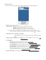
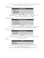
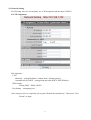
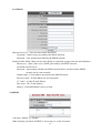
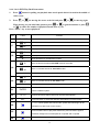
USER MANUAL
4/9/16 CHANNELS
DIGITAL VIDEO RECORDER
CYBER VIEW
REMOTE SURVEILLANCE SOFTWARE USER GUIDE
i
INSTRUCTION MANUAL
To obtain the best performance and ensure device function correctly, please read this
instruction manual carefully and completely.
FCC Compliance
USER-INSTALLER CAUTION:
YOUR AUTHORITY TO OPERATE THIS FCC VERIFIED
EQUIPMENT COULD BE VOIDED IF YOU MAKE CHANGES OR MODIFICATIONS NOT
EXPRESSLY APPROVED BY THE PARTY RESPONSIBLE FOR COMPLIANCE TO PART 15 OF
THE FCC RULES.
NOTE:
THIS EQUIPMENT HAS BEEN TESTED AND FOUND TO COMPLY WITH THE LIMITS
FOR A CLASS A DIGITAL DEVICE, PURSUANT TO PART 15 OF THE FCC RULES.
THESE
LIMITS ARE DESIGNED TO PROVIDE REASONABLE PROTECTION AGAINST HARMFUL
INTERFERENCE WHEN THE EQUIPMENT IS OPERATED IN A COMMERCIAL ENVIRONMENT.
THIS EQUIPMENT GENERATES, USES, AND CAN RADIATE RADIO FREQUENCY ENERGY
AND IF NOT INSTALLED AND USED IN ACCORDANCE WITH THE INSTRUCTION MANUAL,
MAY CAUSE HARMFUL INTERFERENCE TO RADIO COMMUNICATIONS.
OPERATION OF THIS EQUIPMENT IN A RESIDENTIAL AREA IS LIKELY TO CAUSE HARMFUL
INTERFERENCE IN WHICH CASE THE USER WILL BE REQUIRED TO CORRECT THE
INTERFERENCE AT HIS OWN EXPENSE.
THIS CLASS A DIGITAL APPARATUS MEETS ALL REQUIREMENTS OF THE CANADIAN
INTERFERENCE-CAUSING EQUIPMENT REGULATIONS.
ii
Warnings and Cautions
WARINGS
TO PREVENT THE RISK OF FIRE OR ELECTRIC SHOCK.
DO NOT EXPOSE THIS PRODUCT
TO RAIN OR MISTURE.
DO NOT INSERT ANY METALLIC OBJECT THROUGJ VENTILATION GRILLS.
CAUTION
CAUTION
RISK OF ELECTRIC SHOCK
DO NOT OPEN
CAUTION: TO REDUCE THE RISK OF ELECTRIC SHOCK.
DO NOT REMOVE COVER (OR BACK).
NO USER-SERVICEABLE PARTS INSIDE.
REFER SERVICING TO QUALIFIED SERVICE PERSONNEL.
Explanation of Graphical Symbols
The lightning flash with arrowhead symbol, within an equilateral triangle, is
intended to alert the user to the presence of insinuated “dangerous voltage” within
the product’s enclosure that may be of sufficient magnitude to constitute a risk of
electric shock to persons.
The exclamation point within an equilateral triangle is intended to alert the user to
the presence of important operating and maintenance (servicing) instruction in the
literature accompanying the product.
USERS OF THE SYSTEM ARE RESPONSIBLE FOR CHECKING AND COMPLYING WITH ALL
FEDERAL, STATE, AND LOCAL LAWS AND STATUTES CONCERNING THE MONITORING
AND RECORDING OF VIDEO AND AUDIO SIGNALS.
ULTRAK SHALL NOT BE HELD
RESPONSIBLE FOR THE USE OF THIS SYSTEM IN VIOLATION OF CURRENT LAWS AND
STATUTES.
iii
CHAPTER 0 Cyber View Reversion History --------------------------------------------------
1
CHAPTER 1 Minimal system requirement
1.1 Computer hardware
1.2 Software
------------------------------------------------------------------
1
--------------------------------------------------------------------------------- 1
1.3 Installation
------------------------------------------------------------------------------
CHAPTER 2 Operation manual
2.1 Installation method
1
1
-------------------------------------------------------------------
2.2 IE browser setting (only requires first time usage setting)
1
-----------------
2
2.3 Network on-line
-----------------------------------------------------------------------
3
2.4 Network control
-----------------------------------------------------------------------
4
--------------------------------------------------------------------
5
2.5 Record/Snapshot
2.5.1 Record
----------------------------------------------------------------------------
5
-------------------------------------------------------------------------
5
--------------------------------------------------------------------------------
6
2.5.2 Snapshot
2.6 View Log
2.7 System Setting
------------------------------------------------------------------------
2.8 User Management
2.9 Network Setting
------------------------------------------------------------------
8
-----------------------------------------------------------------------
9
2.9.1 IP Assignment
2.9.2 PPPoE
------------------------------------------------------------------
----------------------------------------------------------------------------
2.10 DDNS Setting
------------------------------------------------------------------------
2.11 Alarm and Motion Detection
2.12 DVR Control Panel
2.12 1 4-ch DVR
6
------------------------------------------------------
9
10
10
11
------------------------------------------------------------------ 13
-----------------------------------------------------------------------
2.12.2 9-ch / 16-ch DVR
-------------------------------------------------------------
iv
13
14
Cyber View Reversion History
Version
Date
Modification
3.02
15/Jul/2004
4/9/16-ch DVR,Official release
3.12
01/Oct/2004
Add CF Card Backup function
3.13
26/Oct/2004
Add DDNS Schedule Update function
Cyber View
Remote Surveillance Software Installation Guide
1. Minimal system requirement
1.1 Computer hardware
1. CPU : Intel Pentium or AMD, 800MHz or above
2. Microsoft Windows 98, ME, 2000 or XP
3. 128MB RAM or above
4. 5GB available hard drive space
5. 800x600 display monitor with 16 bit color
1.2 Software
1. Inside the CD there are two types. Cht represents the application program and manual in
Chinese language. Eng represents the application program and manual in English language.
2. Application program: IPInstallerCht.exe: Chinese user interface
IPInstallerEng.exe: English user interface
3. If Microsoft O.S is utilized, inside the computer it is necessary to have IE browser.Ver6.0.
4. If Linux O.S. is utilized, for the setting please refer to the setting of Linux.
1.3 Installation:
As there are different network systems, therefore there are a few different installation methods
that will be introduced separately.
1. (Static IP) fixed IP
2. (Dynamic IP) dynamic IP
3. (PPPoE) dialing method
For various installation methods.
2. Operation manual
2.1 Installation method
Install the IPInstallerEng.exe first and the desk will provide IP scanning function.
If IPInstallerEng.exe is installed, omit the setting explanation in 2.3
IP position setting
Install the machine inside the LAN internal network or utilize cross-over interlaced network
1
cable directly (in the accessories pack) and one computer to conduct direct connection.
step is to set the IP position of the DVR.
Following this execute the IPInstallerEng.exe and the following diagram will appear:
This
The “Device lists” on the left will list out all DVR on LAN. When the equipment is pointed
by the mouse, the right side will show the parameters of various networks. Various
parameters can be revised on it and by pressing the “Submit” on the lower part, the revision
is completed.
Attention: Please input correct network parameters.
Search Device: please search for all devices on the LAN once.
Exit: Exit
2.2 IE browser setting (only requires first time usage setting)
If this setting is already installed with IPInstallerEng.exe, the setting of this explanation can be
exempted.
IEÆtoolÆInternet network optionÆsafetyÆself assigned level
The above three options are all based on reselect as the prompt.
As indicated in the diagram.
1. Tool
2. Internet option
3. Safety
4. Self assigned level
The above three are all set as prompt. During registration, please select 『yes』
2
2.3 Network on-line
After setting up the IP based on the above step, connect to the intended network or LAN.
Execute IE directly on PC. Directly input IP to conduct on-line as the following diagram:
Default:User name:admin,password:admin。
The left side of the above diagram is the control panel and the right side is image display.
3
2.4 Network control
The left area is the control panel of the network as indicated in the following diagram.
Divided into four types of control:
1. Image Adjust::Quality, with three options – High / Medium / Low.
Resolution: three kinds including VGA / CIF / QCIF.
Advances: Brightness/Contrast/Saturation/Hue/Sharpness.
PS:For PAL system 16-ch DVR, VGA resolution, just have only one quality:Low..
For PAL system 8-ch DVR, VGA resolution, just have two kinds quality:Medium /
Low.
2. Operation mode:Continuous and Periodic:
Cyclical and user can select how many seconds interval and then send out
image.
3. Image Capture: Recording and Snapshot. For detail description, please refer to “2.5
Record/Snapshot”.
4. Configuration:
View Log, For detail description, please refer to “2.6 View Log”.
System setting for detail description, please refer to “2.7 System setting”
User Management, for detail description, please refer to “2.8 User Management”
Network setting, for detail description, please refer to “2.9 Network setting”
Dynamic DNS, for detail description, please refer to “2.10 DDNS setting”
Alarm and Motion Detection, for detail description, please refer to “2.11 Alarm
and Motion Detection”
5. DVR Control Panel:for detail description, please refer to “2.12 DVR Control Panel”.
4
2.5 Record/Snapshot
2.5.1 Record
Push “Recording” key, the Panel will appear as the following diagram:
On the most upper part select “Select:
Save as JPEG: will record as JPEG file with one by one image video recording.
Save as AVI: will record as AVI file with one section image video recording.
JPEG and AVI can be set separately:
No limit: no limitation on the size of file.
Number: will limit how many frames in the file is the maximum number.
Size: will limit the maximum capacity of the file by how many Kbytes.
Time: will limit the longest video recording of the file by how many seconds.
Frame rate: how many frames will be recorded within one second.
Save interval: how many frame intervals before conducting video recording again, 1
represents 1 frame.
Maximum Number of Frame Each File: Maximum number of frames for each file.
Save Path: Path of saved file.
Pre Name: Name of the saved file.
“Start” at the most lower part will start the video recording. “Cancel”
2.5.2 Snapshot
Push “Snapshot” key, the Panel will appear the image, save as file.
5
2.6 View Log
These records include:IP that connects to the computer,MAC address,time
However, after the DVR power is turned off, these records will be removed.
2.7 System Setting
There are total 6 subjects need to be set.
1. Server Information
Version:Display the present version.
DVR Title:the name seen at the network end in Chinese and English. Press
“Change” on the lower part to complete.
2. Device’s time setting
6
Device’s time:Can select two kinds – “NTP” time setting or “Input new time”. After
setting, press “Adjust” on the lower part to complete.
3. Language Setting
Can select three kinds:“English” / “Tradition Chinese” / “Simple Chinese”. After
setting, press “Change” on the lower part to complete.
4. DVR Channel Setting
Can select 3 kinds:“four channel DVR” / “eight channel DVR” / “sixteen channel
DVR”. After setting, press “Change” on the lower part to complete.
5. DVR System Setting
Can select 2 kinds:“NTSC System” / “PAL System”. After setting, press “Change”
on the lower part to complete.
6. Others
Reboot DVR:After pressing, only the network card will reboot the machine.
However, the DVR machine will not reboot.
Firmware update:Program of network update on-line. Attach file name .bin
7
2.8 User Management
User authorization required:Yes, set password. No, do not set password.
Add a user or change password: username, password and confirm require being the same. Then
press “Set & Change” to input.
Delete user: User name will list out names of all users. Most upper top “admin” is the highest
level user and cannot be deleted. Others are general users. After it is being pointed,
press “Delete” to delete.
User name list: List out names of all users.
Default:User authorization required:Yes
Username:admin
Password:admin
PS:System will need to reboot when once the administrator username is modified.
8
2.9 Network Setting
For IP setting, there are two methods, one is IP Assignment and the other is PPPoE.
2.91. IP Assignment
IP Assignment:
LAN
Manually:setting IP address / Subnet mask / Default gateway
Automatically by DHCP:setting Send mail after DHCP / DHCP Subject.
DNS Setting:
Setting DNS1 / DNS2 / DNS3
Port Setting:setting http port.
After setting revision is completed, please push “Reboot the immediately”. Then press “Save
Setting” to input.
9
2.9.2 PPPoE
Dial On Power Up:after selection utilizes the PPPoE.
Username:Name of user provided by the PPPoE network.
Password:User password provided by the PPPoE network.
Send mail after dialed:Mail sent out after dialing is completed: suggest selection and utilization
Mail server:name of the server (SMTP) provided by the PPPoE network
Username on mail server:
Password:password provided by the PPPoE network that is set based on the PPPoE
network and it is not essential.
Sender email:E-mail address provided by the PPPoE network.
Receiver email:E-mail address for receiving mail.
CC email:to other E-mail address.
Bcc email:Bcc E-mail address.
Subject:DVR PPP Dialed!, can be revised.
2.10 DDNS
Can select “Enable” or “Disable”
When selecting execution of DDNS, it is necessary to set the Username
10
Schedule Update:Can select 4 kinds – disable / 1 hour / 1 day / 2day。
Submit:Login after the setting is completed.
Example:Username:test
State status information:
z
Register DNS Entry:http://test.ddns.camddns.com
z
z
z
z
DDNS registration successful, can now log in the DVR by http://test.ddns.camddns.com.
Updating Failed, The name test is already registered
Representing the name already been taken.
Updating Failed, Please check your internet connection.
Representing connection problem, please check with your network connection status and
make sure network setting has been set properly. Please also check the DNS field which
under ConfigurationÆNetwork has also been set properly.
UpdatingÆ Updating, please wait.
Not Update / IdleÆ No auction is performed.
2.11 Alarm and Motion Detection
This function allow you to send out images by email or FTP when motion or alarm are
triggered.
Mail Setting
Mail server:name of the server (SMTP) provided by the network
Username on mail server:provided by the network
Password:password provided by the network that is set based on the network and it is not
essential.
Sender email:E-mail address provided by the network.
Receiver email:E-mail address for receiving mail.
CC email:to other E-mail address.
11
Bcc email:Bcc E-mail address.
Subject:DVR Warning!, can be revised.
Send mail when alarm and motion detected:must check to perform this function.
FTP Setting
Ftp Server:Enter either IP address or URL of the FTP server.
Username:Username for accessing the FTP site.
Password:Password for accessing the FTP site.
Port:FTP port number.
Upload path:Enter correct path for uploading. Default value is the root of FTP server if
you leave it empty. Please make sure you have write privilege.
Upload images when alarm and motion detected:Check it to upload images when alarm or
motions are triggered.
Save Setting:Save setting including FTP and email.
12
2.12 DVR Control Panel
2.12.1 4-ch DVR
Part
Label
1-4
1-4
Function
This View button controls FULL SCREEN display from camera 1 – 4 .
5
Quad screen: All cameras are displayed.
6
6 times speed fast rewind mode.
7
Press Stop to stop playback or recording.
8
Press Pause to pause (field by field) for forward.
Press F. Fwd to play video forward at high speed. Press the button again
9
the speed will be change circulative from ×2,×4, , to the highest ×6.
10
Press the Play button to into time search and play video forward.
11
▲
Playback mode:Time Search , increase the number
Event List , Move the cursor upward
12
▼
Playback mode:Time Search , decrease the number
Event List , Move the cursor downward .
13
1. Playback mode:Move the cursor rightward.
13
ENTER
2. You can use ENTER key to indicates H.D.D status when system is not
under Menu mode.
2.12.2 9-ch/16-ch DVR
For 9-channel DVR
For 16-channel DVR .
14
9-ch / 16-ch DVR Play Back Instruction:
1.
Press
button for pulling out playback time search panel which is located in the middle of
video screen.
2.
Press
or
for moving the cursor to the left and press
When moving on your ideal time position, press
or
or
for moving right.
to gain the number or press
or
to reduce the number of playback month, date or year.
Press “Enter” key to start playback.
Part
Label
1-16
1-9 or 1-16
9
17
16
▲
16
▼
16
◄
16
►
21
ENTER
22
AUTO
23
SEL
24
25
26
Select 9 camera formats at 16ch DVR model.
Select full screen of camera at 9ch DVR model.
Select quad formats at 16ch DVR model.
Select 8 camera formats at 9ch DVR model in live mode.
Select 13 camera formats at 16ch DVR model.
Move leftward or decrease the number
9
20
Select quad formats at 9ch DVR model.
Move downward or decrease the number.
9
19
This View button controls FULL SCREEN display from camera 1-9 or 1-16.
Move upward or increase the number.
9
18
Function
Select 9 camera formats at 9ch DVR model.
Select 16 camera formats at 8ch DVR model.
Move rightward or increase the number
Press ENTER button to make choose or move cursor forward or make
confirm in MENU system
Press AUTO SW to switch channel by channel automatically.
Press this button to select the different assembled of camera formats.
2 / 4 / 6 / 8 times speed fast rewind mode, speed and rewind sign will be
indicated in top left corner on the screen.
Press the Rew button to play video backward, press the button again to
circulative change from normal speed to 1/2 speed and 1/4 speed
Press Field Rew to pause video backward
15
27
Press Stop to stop playback
28
Press Field Fwd to pause video forward
29
30
Press the Play button to play video forward, press the button again to
circulative change from normal speed to 1/2 speed and 1/4 speed
Press F. Fwd to play video forward at high speed. Press the button again
the speed will be change circulative from ×2,×4,×6, to the highest ×8.
16