1
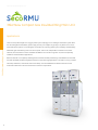
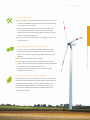
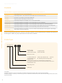
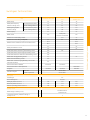
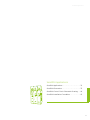
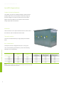
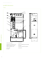
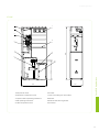
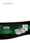
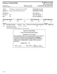
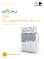
GE
Industrial Solutions
36kV
Gas Insulated Ring Main Unit
Leading the future of electrification
About GE
GE (NYSE: GE) works on things that matter. The best people and the best technologies taking on
the toughest challenges. Finding solutions in energy, health and home, transportation and
finance. Building, powering, moving and curing the world. Not just imagining. Doing. GE works.
For more information, visit the company's website at www.ge.com.
Follow GE’s Industrial Solutions business on Twitter @GEindustrial.
Industrial Solutions
Industrial Solutions, a GE heritage business, is leading the future of electrification with
advanced technologies that protect and control the distribution of electricity throughout a
facility's infrastructure. We provide customers, across various industries, with end-to-end
product and service solutions that ensure the reliability and protection of the electrical
infrastructure; from the substation, to a facility's critical equipment, and all the power
technologies in between.
Honour
2013
2010 World's Most Innovative Companies
2013 World’s Most Admired Companies
2012 World’s Most Respected Companies
2012 Best Global Brand
2010 World’s Most Respected Companies
36kV
New Compact Gas Insulated Ring Main Unit
Leadingthe
thefuture
futureofofelectrification
electrification
Leading
Contents
General Introduction
About GE
GE Industrial Solutions
36kV Gas Insulated Ring Main Unit
Applications . . . . . . . . . . . . . . . . . . . . . . . . . . . . . . . . . . . . . . . . . . . . 02
Operating Conditions . . . . . . . . . . . . . . . . . . . . . . . . . . . . . . . . . . . 04
Features and Benefits . . . . . . . . . . . . . . . . . . . . . . . . . . . . . . . . . . 06
Standards . . . . . . . . . . . . . . . . . . . . . . . . . . . . . . . . . . . . . . . . . . . . . . 08
Product Type . . . . . . . . . . . . . . . . . . . . . . . . . . . . . . . . . . . . . . . . . . . 08
Switchgear Technical Data. . . . . . . . . . . . . . . . . . . . . . . . . . . . . . 09
Basic Functional Module Units
Load Break Switch Unit (K Unit) . . . . . . . . . . . . . . . . . . . . . . . . . . 11
Switch-Fuse Combination Unit (T Unit) . . . . . . . . . . . . . . . . . . . 12
Vacuum Circuit Breaker Unit (V Unit) . . . . . . . . . . . . . . . . . . . . . 13
Bus Tie Unit (I Unit) . . . . . . . . . . . . . . . . . . . . . . . . . . . . . . . . . . . . . . 14
Cable Lifting Unit (C Unit) . . . . . . . . . . . . . . . . . . . . . . . . . . . . . . . . 15
Cable Lifting Unit with Earthing Switch (Re Unit) . . . . . . . . . . 16
SecoRMU Configuration
SecoRMU Configuration . . . . . . . . . . . . . . . . . . . . . . . . . . . . . . . 18
Transformer Protection by Switch Fuse Combination . . . . 25
Measurement, Protection and Control . . . . . . . . . . . . . . . . . . 26
Tools and Accessorie . . . . . . . . . . . . . . . . . . . . . . . . . . . . . . . . . . 29
SecoRMU Applications
SecoRMU Applications . . . . . . . . . . . . . . . . . . . . . . . . . . . . . . . . . 32
SecoRMU Dimensions . . . . . . . . . . . . . . . . . . . . . . . . . . . . . . . . . 33
SecoRMU Control Circuit Schematic Drawing . . . . . . . . . . . 40
SecoRMU Installation Foundation . . . . . . . . . . . . . . . . . . . . . . 43
36kV Gas Insulated Ring Main Unit
36kV New Compact Gas Insulated Ring Main Unit
Applications
There are many advantages of a ring type power system topology over a radial type distribution system. With
the use of Ring Main Units (RMUs), power supply recovery can happen very quickly if any failure occurs in the
36kV Gas Insulated Ring Main Unit
power distribution system. It provides great contribution for improving power system reliability and availability.
02
Meanwhile, gas insulated ring main units are compact, safe to use, independent of ambient environment
influence, and convenient to install. The 36KV SecoRMU is such a kind of ring main unit, which is especially
suitable for kiosk substation applications.
With the features of a completely sealed gas tank, a flexible modular panel design, extendable from both ends,
the 36kV SecoRMU provides integrated solutions for most switching applications in wind farm, mining, compact
secondary substation, commercial center and industry. The extendable feature allows customer to build
functional module units into various solutions to suit their requirements.
36kV Gas Insulated Ring Main Unit
36kV Gas Insulated Ring Main Unit
03
36kV Gas Insulated Ring Main Unit
Operating Conditions
Normal operating conditions
The switchgear is fundamentally designed for the normal service
conditions for indoor switchgears to IEC 62271-1.
● Ambient temperature
Maximum: +40℃
Minimum: - 25℃
Daily average maximum temperature +35℃
● Humidity
Daily average relative humidity: ≤ 95%
Monthly average relative humidity: ≤ 90%
36kV Gas Insulated Ring Main Unit
Daily average vapor pressure: ≤ 2.2×10⁻³MPa
Monthly average vapor pressure: ≤ 1.8×10⁻³MPa
● The maximum site altitude is 1000m above sea level
● The ambient air is not significantly polluted by dust, smoke,
corrosive and/or flammable gases, vapours or salt. The
manufacturer will assume that, in the absence of specific
requirements from the user, there are none.
● Electromagnetic interference in the secondary systemshall be less
than 1.6kV
Special operating conditions
In accordance with IEC 62271-1, the manufacturer and end-user
must agree on special operating conditions which deviate from
operation under normal conditions. The manufacturer/supplier must
be consulted in advance if special severe operating conditions are
involved. Such as:
● Altitude above 1000m
● Ambient temperature higher than +40℃ or lower than -25℃
● Avoid corrosion in control room or other hazards in the following
areas. Install anti-condensation controller and heater if required.
-High humidity areas
-Large temperature difference or fast fluctuation areas
04
36kV Gas Insulated Ring Main Unit
Application
36kV Gas Insulated Ring Main Unit
05
36kV Gas Insulated Ring Main Unit
Features and Benefits
Safe and Reliable
● Both the gas tank and cable compartment are internal arc classified (AFLR 20kA/1s), ensuring
maximum personal safety. When an internal arc fault occurs, the pressure relief device will open,
allowing the pressurized gas to flow via the arc duct away from the operator
● All the high voltage live parts are fully sealed in the gas tank and free from environmental impacts.
Therefore, SecoRMU is suitable for use under severe operating conditions with the primary live parts
remaining maintenance free
● Panel connected together without any clearance between them, which protects the switchgear
against the harmful effects of dust, water, solid foreign objects etc., realize high reliability
● Successfully proven by 500 hour salt fog test suitable for highly corrosive environments
● SecoRMU is equipped with reliable mechanical and electrical interlocking system. Castell and
36kV Gas Insulated Ring Main Unit
Fortress key interlocking solutions are also available, guarantees safety of personnel, safety of
equipment, and continuity of operation
Compact Design
● An optimized electric field design combined with excellent insulating performance, results in a
compact switchgear product that operates safely and reliably
● Existing switchgear rooms can be used more effectively
● Suits application in very compact areas
MV Switchgear
06
36kV Gas Insulated Ring Main Unit
Very Low Maintenance
● Heat loss (I2R) is mainly caused by circuit resistance. The main circuit
resistance of SecoRMU is small resulting in low heat losses and less
thermal stress on the equipment
● The 3mm thick stainless steel gas tank is manufactured by laser
cutting and laser welding process. Its sealing is systematically
checked by automatic helium leakage detection process, ensuring
less than 0.1% annual leakage rate
● Very low maintenance and operation cost, resulting in a lower total
Modular design Extendable and Combine Freely
● The basic functional modules being the load break switch panel,
switch-fuse panel and circuit breaker panel have uniform width
(440mm). Convenient for system design, flexible replacement and
upgrading
● Each unit can be extended to the left or right
● Joined together by plug-in busbar connectors and the modular
nature of the panel ensure ease of installation and extension without
the need for extra gas handling activities on site
● The big cable compartment also ensures a convenient cable
36kV Gas Insulated Ring Main Unit
cost of ownership
installation and connection
Environmental, Health and Safety of Materials
GE has strict process to ensure regulations for the environment, health
and safety of materials used during product design and manufacturing
are observed. Only re-usable and/or recyclable materials are used
in producing SecoRMU switchgear. It reflects GE's commitment to
environmental challenges while delivering valuable products and
services to the customer
07
36kV Gas Insulated Ring Main Unit
Standards
36kV Gas Insulated Ring Main Unit
36kV SecoRMU is manufactured and tested in accordance with the latest version of:
IEC 60282-1
High-Voltage Fuses –Part 1: Current-limiting fuses
IEC 60265-1
High-voltage switches – Part1: Switches for rated voltages above 1 kV and less than 52 kV
IEC 60376
Specification and acceptance of new Sulfur Hexafluoride
IEC 60529
Degrees of protection provided by enclosures (IP code)
IEC 62271-1
High-voltage switchgear and controlgear - Part 1: Common specifications
IEC 62271-100
High-voltage switchgear and controlgear – Part 100: Alternating-current circuit-breakers
IEC 62271-102
High-voltage switchgear and controlgear – Part 102: Alternating current disconnectors and earthing switches
IEC 62271-103
High-voltage switchgear and controlgear – part 103: Switches for rated voltages above 1kV up to and including 52kV
IEC 62271-105
High-voltage switchgear and controlgear – Part 105: Alternating current switch-fuse combinations
IEC 62271-200
High-voltage switchgear and controlgear – Part 200: AC metal-enclosed switchgear and controlgear for rated voltages
above 1kV and up to and including 52 kV
All other corresponding IEC publications, national or local safety regulations must be followed during the installation and operation of
the switchgear. In addition, any project specific advice from GE must be considered.
Product Type
SecoRMU 36 -
/
Extension mode
I: Left extendable
ID: Both sides extendable
D: Right extendable
NA: Non-extendable
Rated current: 630A
K: Load break switch unit. T: Switch-fuse combination unit
V: VCB unit.
CL/CR: Cable lifting unit.
Re: Cable lifting unit (with earthing switch)
IL/IR: Bus tie unit
(Common-tank ring main unit is combined freely by individual units.
For example, KK denotes a two-unit common-tank solution made of two
load break switch units)
Rated voltage: 36kV
Product type
For example:
SecoRMU 36-V/630ID is a vacuum circuit breaker unit with 36kV rated voltage and 630A rated current, both sides extendable.
SecoRMU 36-KK/630D is a two-way common-tank ring main unit, made of two load break switch units, with 36kV rated voltage and 630A rated current,
right side extendable.
08
36kV Gas Insulated Ring Main Unit
Item
Rated voltage
Rated power frequency
withstand voltage (1min)
Rated lightning impulse
withstand voltage
Unit
Load Break Switch Unit
Switch-Fuse Combination
Unit
Vacuum Circuit
Breaker Unit
kV
36
36
36
To earth/phase to phase
kV
70
70
70
Across isolating distance
kV
80
80
80
To earth/phase to phase
kV
170
170
170
Across isolating distance
kV
195
195
195
Hz
50
50
50
630
Limit by fuse
(630A for main busbar)
630
31.5
20
82
52
Rated frequency
Rated current
A
Rated short circuit breaking current
kA
Rated short circuit making current(peak)
kA
Rated short time withstand current and endurance time
kA/s
52
20/3
20/3
25/1
25/1
52
52
65
65
Rated peak withstand current
kA
Load breaker switch rated active load breaking current
A
630
Load breaker switch rated closed loop breaking current
A
630
Load breaker switch 5% rated active load breaking current
A
31.5
Rated cable charging breaking current
A
50
Rated earth fault breaking current
A
150
Rated cable- and line-charging breaking current under
earth fault conditions
A
86
Mechanical endurance (LBS/ES)
5000/2000
630
50
3000/2000
Mechanical endurance (VCB/3p switch)
10000/2000
IP degrees
Internal arc degree
IP67/IP4X
IP67/IP4X
Gas tank
AFLR 20kA/1s
Cable compartment
AFLR 20kA/1s
IP67/IP4X
36kV Gas Insulated Ring Main Unit
Switchgear Technical Data
Gas System
Insulated gas
SF6
Annual leakage rate
≤ 0.1%/Y
Rated gas pressure (rel, 20˚C)
MPa
0.04
0.04
0.04
Alarm low pressure (rel, 20˚C)
MPa
0.03
0.03
0.03
Minimum operating pressure (rel, 20˚C)
MPa
0.02
0.02
0.02
Auxiliary Circuit
Rated voltage of auxiliary circuit
V
24/48/110/220 DC
110/230/240 AC
1 min power frequency withstand voltage of
auxiliary circuit
kV
2
09
36kV Gas Insulated Ring Main Unit
Basic Functional Module Units
Load Break Switch Unit (K Unit). . . . . . . . . . . . . . . . . . 11
Switch-Fuse Combination Unit (T Unit) . . . . . . . . . . . 12
Basic Functional Module Units
Vacuum Circuit Breaker Unit (V Unit) . . . . . . . . . . . . . 13
10
Bus Tie Unit (I Unit) . . . . . . . . . . . . . . . . . . . . . . . . . . . . . 14
Cable Lifting Unit (C Unit) . . . . . . . . . . . . . . . . . . . . . . . 15
Cable Lifting Unit with Earthing Switch (Re Unit) . . 16
Basic Functional Module Units
Basic Functional Module Units
Load Break Switch Unit (K Unit)
K
Function
Dimensions:
● Connect or disconnect the incoming/outgoing cable with the
Width: 440mm
main busbar
Depth: 920mm
● Earthed three-phase cables
Height: 1950mm
● Making short circuit current
Weight: 300kg
Standard configuration
● Two-position load break puffer switch and separate earthing
switch
● Manual operating mechanisms with two separate operating
shafts for load break function and earthing function
● Switch position indication for load break switch and earthing
switch
● Potential indicator
● SF6 gas pressure meter
● Interlocking between the earthing switch and the cable
Load break switch
SecoLBS-K 36
compartment door
Rated voltage
36kV
● Main busbar/feeder busbar/earthing bar
Rated frequency
50Hz
● Cable bushings horizontal in front
Rated power frequency To earth/phase to phase
withstand voltage
Across isolating distance
(1min)
70kV
● Operating handle
Rated lightning
impulse withstand
voltage
80kV
To earth/phase to phase
170kV
Optional Features
Across isolating distance
195kV
● No earthing switch
● Motorized operating mechanism of load break switch
Rated current
630A
Rated active load breaking current
630A
● Ring CT
Rated closed loop breaking current
630A
● LV compartment
5% rated active load breaking current
31.5A
Rated cable charging breaking current
50A
● Cable terminals
Rated earth fault breaking current
150A
Rated cable- and line-charging breaking current under
earth fault conditions
86A
Rated short circuit making current (peak)
52kA
Rated short time withstand current and endurance time
20kA/3s
Electrical Endurance
E2
● Main busbar left/right out-cone bushing
Mechanical endurance
5000 times
● Castell or Fortress key interlock
Earthing Switch
SecoES 36
Rated voltage
36kV
Rated power frequency withstand voltage (1min)
70kV
Rated lightning impulse withstand voltage
170kV
Rated short circuit making current(peak)
52kA
Rated short time withstand current and endurance time
20kA/3s
Mechanical endurance
2000 times
● Surge Arrester
● Short circuit and earth fault indicator
Basic Functional Module Units
Technical Data
● Auxiliary contacts for load break switch position 3NO+3NC
● Auxiliary contacts for earthing position 2NO+2NC
11
36kV Gas Insulated Ring Main Unit
Basic Functional Module Units
Switch-Fuse Combination Unit (T Unit)
T
Function
Dimensions:
Control and protect transformers up to 2000kVA.
Width: 440mm
Depth: 1000mm
Height: 1950mm
Weight: 400kg
Standard configuration
● Fuse/transformer rating: 36kV, max 63A fuse-links
● Two-position load break puffer switch and separate upstream
earting switch mechanically linked with downstream earthing
switch
● Manual operating mechanisms with two separate operating
shafts for load break function and earthing function
● Fuse holder for DIN type fuse-links. Only accessible when
earthing switch is closed
● Fuse tripping arrangement
● Switch position indication for load break switch and earthing
switch
● Fuse trip indication
● Potential indicator
Technical Data
Basic Functional Module Units
Switch fuse combination
SecoLBS-T 36
Rated voltage
36kV
Rated power frequency To earth/phase to phase
withstand voltage
Across isolating distance
(1min)
70kV
80kV
● SF6 gas pressure meter
● Interlocking between the earthing switch and the cable
compartment door
● Main busbar/feeder busbar/earthing bar
● Cable bushings horizontal in front
Rated lightning
impulse withstand
voltage
To earth/phase to phase
170kV
Across isolating distance
195kV
Rated current
Main busbar
630A
Optional Features
Switch fuse combination
● Operating handle
*
● Motorized operating mechanism of Load Break switch
Rated short circuit breaking current
31.5kA
● Opening coil
Rated active load breaking current
630A
Transfer Current
750A
● Ring CT
Mechanical endurance
3000 times
Earthing Switch
SecoES 36
Rated voltage
36kV
● Surge Arrester
Rated power frequency withstand voltage (1min)
70kV
● Short circuit and earth fault indicator
Rated lightning impulse withstand voltage
170kV
● Auxiliary contacts for load break switch position 3NO+3NC
Rated short circuit making current(peak)
52kA
Rated short time withstand current and endurance time
20kA/3s
● Auxiliary contacts for earthing position 2NO+2NC
Mechanical endurance
2000 times
● LV compartment
● Cable terminals
● Auxiliary contacts for fuse blown 1NO
● Main busbar left/right out-cone bushing ● Castell or Fortress key interlock
12
Basic Functional Module Units
Vacuum Circuit Breaker Unit (V Unit)
V
Function
Dimensions:
Used for circuit protection, motor protection and
Width: 440mm
transformer protection.
Depth: 920mm
Height: 1950mm
Standard configuration
● SecoVac-R 36 vacuum circuit breaker
Weight: 350kg
● IST 36 three-position switch
● Motorized operating mechanism for the vacuum circuit breaker
● Interlocking between the VCB and the 3p switch
● Interlocking between the earthing switch and the cable
compartment door
● Switch position indication for vacuum circuit breaker,
disconnector and earthing switch
● Potential indicator
● SF6 gas pressure meter
● Main busbar/feeder busbar/earthing bar
Technical Data
● Cable bushings horizontal in front
Vacuum Circuit Breaker
SecoVac-R 36
Rated voltage
36kV
Rated power frequency withstand voltage (1min)
70kV
Rated lightning impulse withstand voltage
170kV
Rated current
630A
Rated short circuit breaking current
20kA
● Self-powered relay WIC1 with CT
Rated short circuit making current(peak)
52kA
● Trip coil (for relay tripping)
Rated short time withstand current and endurance time
20kA/3s
● Undervoltage release
Rated cable charging current
50A
● LV compartment
Class
E2/C2
● Cable terminals
Mechanical endurance
10000 times
● Short circuit and earth fault indicator
Operating Sequence
O-0.3s-CO180s-CO;
O-0.3s-CO15s-CO
Three-position switch
IST 36
● Auxiliary contacts for earthing position 5NO+3NC
Rated voltage
36kV
Rated power frequency withstand voltage (1min)
70kV
Rated lightning impulse withstand voltage
170kV
Rated peak withstand current
50kA
Rated short time withstand current and endurance time
20kA/3s
Mechanical endurance
2000 times
Optional Features
● Cancel earthing switch of the 3p switch
● Surge Arrester
● Auxiliary contacts for vacuum circuit breaker position 5NO+6NC
Basic Functional Module Units
● Operating handle
● Auxiliary contacts for disconnector position 5NO+3NC
● Main busbar left/right out-cone bushing
● Castell or Fortress key interlock
13
36kV Gas Insulated Ring Main Unit
Basic Functional Module Units
Bus Tie Unit (I Unit)
IL/IR
Dimensions:
Width: 600mm
Depth: 920mm
Height: 1950mm
Weight: 400kg
IL Type Bus Tie Unit
IR Type Bus Tie Unit
Technical Data
Function
Basic Functional Module Units
Load break switch
SecoLBS-K 36
Rated voltage
36kV
Rated frequency
50Hz
Rated power
To earth/phase to phase 70kV
frequency withstand
Across isolating distance 80kV
voltage (1min)
Rated lightning
impulse withstand
voltage
To earth/phase to phase 170kV
Across isolating distance 195kV
or sectionalizing. Easy maintenance by earthing one section of the busbar.
Standard configuration
● Two-position load break puffer switch and separate earthing switch
● Manual operating mechanisms with two separate operating shafts for
load break function and earthing function
● Switch position indication for load break switch and earthing switch
Rated current
630A
Rated active load breaking current
630A
Rated closed loop breaking current
630A
● SF6 gas pressure meter
Rated cable charging breaking current
50A
● Main busbar/feeder busbar/earthing bar
Rated earth fault breaking current
63A
Rated cable- and line-charging breaking
current under earth fault conditions
● Operating handle
86A
● Both sides extendable
Rated short circuit making current(peak)
52kA
● Busbar connector
Rated short time withstand current and
endurance time
20kA/3s
Electrical Endurance
E2
Mechanical endurance
5000 times
Earthing Switch
SecoES 36
● Motorized operating mechanism of load break switch
Rated voltage
36kV
● LV compartment
Rated power frequency withstand voltage (1min) 70kV
14
Connect or disconnect two main busbar sections, realizing busbar coupling
Rated lightning impulse withstand voltage
170kV
Rated short circuit making current(peak)
52kA
Rated short time withstand current and
endurance time
20kA/3s
Mechanical endurance
2000 times
● Potential indicator
Optional Features
● Cancel earthing switch
● Surge Arrester
● Auxiliary contacts for load break switch position 3NO+3NC
● Auxiliary contacts for earthing position 2NO+2NC
● Castell or Fortress key interlock
Basic Functional Module Units
Cable Lifting Unit (C Unit)
CL/CR
Dimensions:
Width: 440mm
Depth: 920mm
Height: 1950mm
Weight: 150kg
CR Cable Lifting Unit
Technical Data
Function
Used for connecting with incoming/outgoing cables
Cable Lifting Unit
Rated voltage
36kV
Rated frequency
50Hz
Rated power frequency withstand voltage (1min)
70kV
● Potential indicator
Rated lightning impulse withstand voltage
170kV
● One sides extendable
Rated current
630A
● The cable compartment door interlock
Rated short time withstand current and endurance time
20kA/3s
Standard configuration
Optional Features
● Ring CT
● Cable terminals
● Surge Arrester
Basic Functional Module Units
CL Cable Lifting Unit
15
36kV Gas Insulated Ring Main Unit
Basic Functional Module Units
Cable Lifting Unit with Earthing Switch (Re Unit)
Re
Dimensions:
Width: 440mm
Depth: 920mm
Height: 1950mm
Weight: 250kg
Technical Data
Function
Used for connecting with incoming/outgoing cables and earthing
Basic Functional Module Units
Cable Lifting Unit with Earthing Switch
main busbar
Rated voltage
36kV
Rated frequency
50Hz
Rated power frequency withstand voltage (1min)
70kV
Rated lightning impulse withstand voltage
170kV
● SecoES 36 type of earthing switch
Rated short time withstand current and endurance time
20kA/3s
● Manual operating mechanisms for the earthing switch
Rated short circuit making current(peak)
52kA
● Potential indicator
Mechanical endurance
2000 times
● SF6 gas pressure meter
Standard configuration
● Interlocking between the earthing switch and the cable
compartment door
● Main busbar/feeder busbar/earthing bar
● Cable bushings horizontal in front
● Operating handle
Optional Features
● Cancel earthing switch
● Ring CT
● LV compartment
● Cable terminals
● Surge Arrester
● Short circuit and earth fault indicator
● Auxiliary contacts for earthing position 2NO+2NC
16
SecoRMU Configuration
SecoRMU Configuration
SecoRMU Configuration
SecoRMU Configuration . . . . . . . . . . . . . . . . . . . . . . . 18
Transformer Protection by Switch Fuse Combination
. . . . . . . . . . . . . . . . . . . . . . . . . . . . . . . . . . . . . . . . . . . . . . . 25
Measurement, Protection and Control . . . . . . . . . . 26
Tools And Accessorie . . . . . . . . . . . . . . . . . . . . . . . . . . 29
17
36kV Gas Insulated Ring Main Unit
SecoRMU Configuration
SecoRMU Front Panel
1 Low voltage compartment
1
2
5
3
4
The LV compartment on top of the switchgear can be equipped with
secondary components, a condensation monitor, a remote control unit,
additional communication device, meters etc.
Dimensions:
Width: N×440mm
Depth: 360mm
Height: 200mm or 500mm
6
7
9
SecoRMU Configuration
11
2 Mechanical lock
8
Low voltage compartments are integrated with hinged door. Access to
the hinged door is controlled by a keyed lock.
10
3 Capacitive high voltage indicator
The capacitive high voltage indicator works in conjunction with the
12
integrated sensor to detect the live condition of the incoming/outgoing
feeder. If also verifies the safe isolation from the supply.
The capacitive high voltage indicator with interlock function can lock
the switchgear to prevent any dangerous operation or access when the
14
equipment is live.
Test sockets are available on the front panel for phase checking.
13
4 Open/Close button (if motorized operated)
Open button in red also shows the switch 'ON' condition.
Close button in green also shows the switch 'OFF' condition.
Each button is equipped with a plastic cover in front of it, to prevent the
accidental pressing.
5 Heat Monitor
When the ambient humidity reaches ≥ 60%RH±5%, the heater switches
on to control the humidity and temperature inside the switchgear.
The sensor is mounted in the side wall of the cable compartment.
6 Panel labels
Shows panel description according to customer request.
7 Gas pressure viewing window
The viewing window allows viewing of the pressure indicator of the gas
tank.
18
Instruction for load break switch manual operation, including maintenance
operation steps and energizing operation steps.
9 Front cover
Covers are manufactured of cold-roll steel sheet with painting.
Color for mechanism compartment cover is RAL 7040; while the upper and lower
front covers are of the color RAL 9003.
10 Simulation single line diagram
Highly visible representative diagram shows the main configuration of the
switchgear. Position indicators show the status of the load break switch and
earthing switch.
Screen painting process makes the single line diagram extremely durable.
11 Operating aperture/interlock selector
Insert operating handle into the aperture to operate the load break switch or the
earthing switch. There is mechanical interlocking between the two switches. Move
the interlock selector the left side, the earthing switch aperture will be exposed.
Move the interlock selector to the right side, the load break switch aperture will be
exposed.
12 Interlock lever
There is mechanical interlocking between the earthing switch and cable
compartment door. When earhing switch is operated to the closed position, lift the
interlock lever and remove the cable compartment door.
13 Cubicle frame
Cubicle frame is not only the basic part for components assembling, but also
used to support and fix the gas tank.The frame is made of no less than 2mm thick
Aluminum-zinc coated plate and assembled by high strength bolts and rivet nuts.
14 Toolbox
SecoRMU Configuration
8 Operation labels
Configuration
SecoRMU Configuration
There is delicate toolbox design on the side of the panel, with user manual,
operating handles, charging handle etc. inside. Operators will find the relative tools
and documents on site more conveniently.
19
36kV Gas Insulated Ring Main Unit
SecoRMU Configuration
Load Break Switch Unit
Roof plate
Busbar extension bushing
● The load break switch is assembled in
the sealed gas tank filled with SF6. It is of
Pressure Gauge
Gas tank
straight-moving puffer design with strong
Load break switch
interrupting capacity
Operating mechanism
● The speed and strength of LBS and ES
operation is determined by the spring-driven
Pressure relief device
mechanism, which will not be influenced by
different operators
● The switch positions are close and open. In
Pressure relief channel
Cable compartment
Cable bushing
the open position, the switch satisfies the
SecoRMU Configuration
disconnector requirements
● There is mechanical interlocking between
Pressure relief flap
Enclosure
LBS operation shaft and ES operation shaft
Switch-Fuse Combination Unit
Vacuum Circuit Breaker Unit
● The switch-fuse combination unit is composed of high breaking
● The vacuum circuit breaker unit has 3 vacuum bottles for
current-limit fuse, two position load break switch and separate
earthing switch
● The fuse which is fitted in the epoxy casted insulating canister
plays an important role in protecting up to 2000kVA transformer
● When short circuit happens, the striker pin can activate the
mechanism of the LBS. The LBS will trip immediately and the
current is broken by the fuse
● The downstream earthing switch, which has connection with
● The vacuum circuit breaker is equipped by a modularized
spring-charging mechanism, which can be operated
manually or electrically. Thanks to the optimized design,
fewer components are used and high reliability is realized
● The moving contact of the three-position switch achieves
3 stable positions, makes natural interlocking
● The mechanical interlock is provided to make it impossible
the main earthing switch, makes the feeder side of the T panel
to operate the 3p switch when the circuit breaker is in the
earthed reliably. When carry
closed position
out earthing operation, the
downstream earthing switch
will be operated aligned with
the main earthing switch to
ensure both sides of the fuse
are earthed reliably. So that
operator can carry out fuse
replacement and installation
in safety
20
extinguishing short circuit current
SecoRMU Configuration
Cable compartment
● The cable compartment consist of cable terminals, earthing bars, cable clamps, HV cables
etc. It is available for mounting ring CT and surge arrester if required
● Cables are bottom entry. Cable compartment allowing max. double cable connection by
using Nexans cable adapters. For 2 cables per phase connections, cable compartment cover
maintain the same depth as the standard unit
● If an arc fault occurs in the cable compartment, the pressure relief device at the rear of the
Cable Terminal
● Shielded type
● Front plug cable connector, rear plug cable connector, rear plug surge arrester
● Applicable standards: EN50181 and DIN47636
410 mm
1 Interface designed to fit front-plug cable connector
SecoRMU Configuration
cable compartment will open, to vent the gas through the arc duct to the bottom of the panel
2 Bus for rear-plug cable connector
3 Conductive EPDM insert
11
2
1
Front-plug
440TB
cable
connector
connector
400 mm
6
8
3
4
7
Rear-plug
cable
connector
5
insert and the jacket
5 Conductive EPDM jacket
6 Conductive EPDM cap
7 Basic insulating plug
10
9
4 Insulating EPDM layer moulded between the
8 Conductor connector (hexagonal crimping, deep
indent crimping or bolted)
9 Cable reducer
10 Earthing lead
155 mm
11 Threaded M16 stud for the equipment bushing
21
36kV Gas Insulated Ring Main Unit
SecoRMU Configuration
Gas System
● The SF6 inside the SecoRMU gas tank
is non-toxic, non-combustible, and
chemically inactive. In the VCB panel,
the making and breaking of the arc is
achieved by the vacuum interrupter,
whilst the SF6 gas provides insulation
● The use of busbar connectors allows
panel installation to be performed
without impacting the gas system.
Temperature compensated pressure
gauge (standard)
Gas density monitor (Optional)
Each gas tank can be equipped with a gas
A simple visual check of the red/green
density monitor, allowing the operator
indicator shows if the panel is ready for
to monitor the gas pressure both locally
service. The red and green area differs
or remotely. In the event of a pressure
at the junction of 1.25bar (20°
C, abs.).
decrease to the set point alarm pressure,
The pointer in the green area shows the
the gas meter will give an alarm signal
normal pressure, the pointer in the red
and/ or trip and/or lock the circuit breaker.
area shows need to re-gas.
Eliminating the need to work with the
gas on site
SecoRMU Configuration
● During an arcing of LBS making and
breaking, some of the insulating
gas decomposes under the high
temperatures. The gas will recompose
and recover after post-arc at lower
temperatures whilst the remainder
will be absorbed by the sorbent in the
tanks
Mechanical Interlocks
● All operating mechanisms are situated
● In the switch-fuse combination panel,
outside the SF6 gas tank and behind
the fuse compartment can only be
the front cover. It's easy to access
accessed when the two sides earthing
the operating mechanism if retrofit or
switches are in the closed position
service should be required
● Push the interlock selector to the left
signal
● In the VCB panel, the mechanical
interlock is provided to make it
impossible to operate the 3p switch
break switch/disconnector when the
when the circuit breaker is in the close
or right, to expose the corresponding
earthing switch is in earthed position.
position
operation apertures to operate the load
It's also impossible to operate the
break switch/disconnector or earthing
earthing switch when the load break
switch
switch/disconnector is in closed
● The cable compartment can only be
accessed when the earthing switch
position
● In the VCB panel, by means of the
is in the closed position.It will also be
mechanical knob it is possible to close
impossible to operate the load break
and open the circuit breaker. The
switch or disconnector or circuit
opening spring is always charged when
breaker or open earthing switch before
the circuit breaker is in closed position
cable compartment door is put back in
and will be ready to open immediately
place
22
● It's impossible to operate the load
if the protection control unit gives a trip
SecoRMU Configuration
Key Interlocking
Medium-voltage key interlocking system between panels or between panels and
upstream or downstream equipment are widely used in IEC market. The purpose is to
prohibit incorrect operation and bring users the following benefits.
key interlocking systems guarantee:
● Safety of personnel
● Safety of equipment
● Sequence of operation
SecoRMU Configuration
Key
Interlocking
SecoRMU can achieve the following applications by use of Castell or Fortress.
23
36kV Gas Insulated Ring Main Unit
SecoRMU Configuration
Pressure Relief System
Arc Relief Device
Each gas tank of SecoRMU is equipped with a pressure
relief device. If an internal arc fault occurs, and the actual
pressure exceeds its designed relief pressure, the pressure
100mm mini
relief device will open, allowing the pressurized gas flow
through to the pressure relief passage to release the
pressure, thus ensures the safety of the equipment and
personnel.
Classification according to
WARNING
evacuation of the SF6 gas
after internal arc happens
Internal arc happens
in the gas tank (1)
500mm
SecoRMU Configuration
IEC62271-200: IAC AFLR 20kA/1s
500mm
Internal arc happens
in the cable
compartment (2)
100mm mini
NOTICE
Minimum dimension of the cable
trench:
Width = 440mm
Depth = 500 mm
Height = 500 mm
500mm
500mm
24
SecoRMU Configuration
Transformer Protection by Switch-Fuse Combination
The striker pin of the fused holder can activate the spring charging mechanism of the load break switch when a
fault occurs. The load break switch will trip immediately and the current will be broken by the fuse.
Fuse Replacement
According to IEC recommendations, when a fuse has blown, all three fuses should be replaced.
d
Ø45
HV fuse meet IEC60282-1 standard. Dimension of SIBA Fuse (Recommended)
35
(length after triggering)
35 (撞针触发后长度)
33
537
Rated Current
Length
(E)
6.3A ≤ In ≤ 25A
31.5A ≤ In ≤ 40A
50A ≤ In ≤ 100A
537mm
Diameter
(D)
53mm
67mm
85mm
Recommended Fuse Ratings for Transformer
( Normal operating with no overload, -25℃ < Φ < 40℃ )
Rated voltage
(kV)
36
36
36
36
36
36
36
36
36
36
36
36
36
36
Transformer Output
(KVA)
100
125
160
200
250
315
400
500
630
800
1000
1250
1600
2000
Uk %
4
4
4
4
4
4
4
4
4
5
6
6
6
6
Fuse link rated current
(A)
6.3
10
10
10
16
16
20
25
31.5
31.5
40
40
63
63
Rated breaking current
(kA)
40
40
40
40
40
40
40
40
40
40
40
40
40
40
SIBA article number
SecoRMU Configuration
33
30 008 13.6.3
30 008 13.10
30 008 13.10
30 008 13.10
30 008 13.16
30 008 13.16
30 008 13.20
30 008 13.25
30 016 13.31.5
30 016 13.31.5
30 016 13.40
30 016 13.40
30 024 13.63
30 024 13.63
Recommended Fuse Ratings for Transformer
( Normal operating with 20% overload, -25℃ < Φ < 40℃ )
Rated voltage
(kV)
36
36
36
36
36
36
36
36
36
36
36
36
36
Transformer Output
(KVA)
100
125
160
200
250
315
400
500
630
800
1000
1250
1600
Uk %
4
4
4
4
4
4
4
4
4
5
6
6
6
Fuse link rated current
(A)
6.3
10
10
16
16
20
25
25
31.5
31.5
40
50
63
Rated breaking current
(kA)
40
40
40
40
40
40
40
40
40
40
40
40
40
SIBA article number
30 008 13.6.3
30 008 13.10
30 008 13.10
30 008 13.16
30 008 13.16
30 008 13.20
30 008 13.25
30 008 13.25
30 016 13.31.5
30 016 13.31.5
30 016 13.40
30 024 13.50
30 024 13.63
Note: Table above is based on SIBA type fuses. If other brand fuse is required, please contact GE in advance.
25
36kV Gas Insulated Ring Main Unit
Measurement, Protection and Control
For more information visit our website: http://www.gedigitalenergy.com/multilin/catalog/3Series.htm
SecoRMU Configuration
Multilin 3 Series
Intuitive industrial and utility
protective relay systems
for feeders, motors and
transformers
Key benefits
● Easy-to-use and cost effective protection and control for
feeders, motors and transformers
● Effortless draw-out construction eliminates requirements for
test switches and reduces downtime
● Environmental monitoring system to alarm on destructive
operating conditions to enable preventative maintenance
● Easy-to-use interface and set up in one simple step
● Accelerated Life Cycle Tested to ensure reliability of relay
operation under abnormal conditions
● Advanced power system diagnostics to increase reliability
through fault and disturbance recording capabilities
● Arc Flash mitigation via zone intertripping, flex curves and
multiple setting groups
● Application flexibility with the use of programmable logic
elements
● Large backlit display with 40 characters for easy viewing of
relay information and settings
● Flexible communications with multiple ports & protocols to
allow seamless integration into new and existing infrastructure
● Easy access to information via multiple communication
network options including USB, Serial, Fiber & Copper Ethernet
● Reduced wiring with support for remote I/O
● Reduced setup and configuration time with the Simplified
Motor Setup screen
● Powerful Security Audit Trail tool to increase security and
minimize system risks by tracking setting changes
Applications
● Advanced protection, monitoring & control relays for feeders
(Multilin 350), motors (Multilin 339) and transformers (Multilin
345)
● Industrial feeders with enhanced breaker monitoring and
diagnostics
26
● Distribution utility downstream breaker protection
● Medium voltage utility feeders with advanced control features
including, cold load pickup, auto reclose and multiple setting
groups
SecoRMU Configuration
Features
Easy-to-use
Protection & control
Drawout construction
(for Multilin 350 Feeder Protection System)
The Multilin 3 Series offers a complete
● Phase, neutral and ground TOC and IOC
drawout feature, eliminating the need for
● Undervoltage, overvoltage, frequency
rewiring after testing has been concluded.
● Neutral/ground directional
The withdrawable feature also eradicates
● Negative sequence overcurrent
the need to disconnect communication
● ANSI, IAC, IEC, flex curves
● Cable Thermal Model protection
Overview
cables, e.g. fiber, copper, RJ45, etc and
helps retain the communication status
● Breaker failure
The Multilin 3 Series of protection relays
even after a relay has been withdrawn
● Cold load pick-up
are highly functional, economical
from its case.
● Four-shot auto reclose
protection relays for feeders, motors and
● 8 digital inputs, 7 contact outputs
transformers. By providing an economical
● Two setting groups
system for protection, control, monitoring
● Event Recorder: 256 events with 1ms
time stamping
● Oscillography with 32 samples per
cycle and digital states
● IRIG-B clock synchronization
● Relay & Asset Health Diagnostics
● Security audit trail
remote user interfaces in one assembly,
the Multilin 3 Series relays effectively
eliminate the need for expensive discrete
components.
The Multilin 3 Series provides detailed
diagnostic information allowing users to
troubleshoot and minimize downtime.
Detailed diagnostics are provided via the
User interface and programming
256 1ms time stamped event recorder
● 4x20 character LCD display
and the 192 cycle Oscillography report
● Control panel with 12 LED indicators
sampled at 32 samples per cycle.
● Front USB and rear serial, Ethernet and
The robust Multilin 3 Series streamlines
Fiber ports
● Multiple protocols - IEC 61850 & 61850
user work flow processes and simplifies
engineering tasks such as configuration,
GOOSE, ModBus ™ RTU, ModBus ™
wiring, testing, commissioning, and
TCP/IP, DNP 3.0, IEC 60870-5-104, IEC
maintenance. This cost-effective relay
60870-5-103
also offers enhanced features such as
EnerVista ™ software
● An industry-leading suite of software
tools that simplifies every aspect of
working with Multilin devices
diagnostics, preventative maintenance,
device health reports and advanced
security features.
Advanced communications
SecoRMU Configuration
and metering, and with both local and
Metering & monitoring
Easy integration into new or existing
infrastructure
With several Ethernet and serial port
options and a variety of communication
protocols, the Multilin 3 Series provides
advanced and flexible communication
selections, enabling seamless integration
into new or existing applications.
The Multilin 3 Series supports various
industry standard protocols such as, IEC
61850 & IEC 61850 GOOSE, Modbus RTU,
Modbus TCP/IP, DNP3.0, IEC 60870-5-104
and IEC 60870-5-103.
● Document and software archiving
toolset to ensure reference material
and device utilities are up-to-date
27
36kV Gas Insulated Ring Main Unit
Enhanced diagnostics
EnerVistaTM Launchpad
Security
Preventative maintenance
EnerVista™ Launchpad is a complete set of
Security audit trail
The Multilin 3 Series allows users to track
powerful device setup and configuration tools
The Multilin 3 Series monitors security
relay exposure to extreme environmental
that is included in the SR relays at no extra
and reliability of asset protection. The
conditions by monitoring and alarming
charge.
Multilin 3 Series protection devices
at high temperatures. This data allows
● Set up the Multilin 3 Series Relays - and any
offer complete traceability of any
users to proactively schedule regular
other Multilin device - in minutes. Retrieve
relay setting and command changes,
maintenance work and upgrading
and view oscillography and event data at
allowing the user to quickly identify
activities.
the click of a button
changes made to the relay.
All relays utilize EnerVistaTM setup
● Build an instant archive on any of the
software for communication, monitoring
latest Multilin manuals, service advisories,
and metering. Actual values, setpoints,
application notes, specifications or
status, trending and waveform capture
firmware for your SR Relay
SecoRMU Configuration
information can all be viewed via
● Automatic document and software version
the software and can be used for
updates via the internet and detailed e-mail
troubleshooting.
notification of new releases
User Interface
● SETPOINT GROUP 1, 2:
These indicators are continuously on if the corresponding group provides settings for protection elements.
TRIP:
The indicator turns on when the relay detects a trip condition.
Operates the trip relay to open the breaker.
ALARM:
While the relay detects an alarm condition, the indicator flashes.
PICKUP:
Indicator lights steady when any protection feature pickup threshold exceeded.
● DISPLAY:
4 line text for easy viewing of key data.
● LEDs:
10 LED indicators for quick diagnostics.
● KEYPAD:
Ten button keypad for access to device interrogation and change of settings.
● FRONT PORT:
An electrically isolated front USB communication port.
Protection Features
ANSI Device Numbers & Functions
BUS
BUS VT
52
79
TRIP
3
CLOSE
1
50N
2
51P
2
51N
1
CLP
1
50_2
1
50BF
49
1
1
59X
59_2
1
1
59N
81U
1
81O
2
2
METERING
1
79
50G/
51G
51G
50G
TRANSIENT RECORDER
EVENT RECORDER
1
350 RELAY
28
27X
1
MONITORING
50P
LOAD
59P
27P
1
2
Device
Number
27P
27X
49
50P
50N
50G
50BF
50_2
51P
51G
51N
59P
59X
59N
59_2
67G
67N
79
81U
81O
CLP
Function
Phase Undervoltage
Auxiliary Undervoltage
Thermal Model
Phase Instantaneous Overcurrent
Neutral Instantaneous Overcurrent
Ground/Sensitive Ground
Instantaneous Overcurrent
Breaker Failure
Negative Sequence Overcurrent
Phase Timed Overcurrent
Ground Timed Overcurrent
Neutral Timed Overcurrent
Phase Overvoltage
Auxiliary Overvoltage
Neutral Overvoltage
Negative Sequence Overvoltage
Ground Directional Overcurrent
Neutral Directional Overcurrent
Autoreclose
Underfrequency
Overfrequency
Cold Load Pickup
Latched Lockout available as a standard feature
SecoRMU Configuration
Tools and Accessories
Busbar Connector
Ring main units are joined together by
plug-in busbar connectors.
The modular nature of the panel ensures
SecoRMU Configuration
ease of installation and extension without
the need for extra gas handling activities
on site.
With the busbar connector, SecoRMU
realizes no clearance connection,
Busbar Extension Bushing
preventing people from touching the high
The inner-cone busbar extension bushing
voltage live parts.
is a gas tight component assembled on
the gas tank for electrical connection. A
white plastic protection cover will be on
the bushing during transportation and
storage.
Inner-cone bushing can be used for
busbar connection and testing adapter
connection.
Cable Bushing
Outer-cone bushing are used for cable
terminal connection. A black plastic
End Plug
protection cover will be on the bushing
Used for sealing the side panel of a
during transportation and storage.
line-up. Keep the switchgear for future
An integrated sensor inside the cable
extension.
bushing, provides a voltage signal to
the potential indicator. The indicator can
display whether the cable is live or not.
The out-cone cable bushing comply to
standard DIN 47636 and EN 50181.
29
36kV Gas Insulated Ring Main Unit
SecoRMU Configuration
Tools and Accessories
Capacitive High Voltage Indicator
Earth Fault Sensing CT
Panels are equipped with capacitive high
The split type zero-sequence CT is
voltage indicator system for testing the
mounted on the feeder side for measuring
circuit live or not.
phase currents and detecting the earth
The high voltage indicator with
fault current. All the power cables in a
interlocking function can provide reliable
interlocking, avoiding misoperation and
entry into the live power equipment.
Short Circuit and Earth Fault
Indicator
The short circuit and earth fault indicator
is designed to detect, display and
remotely indicate phase selective short
circuits and earth faults in medium
voltage distribution networks.
In the power system, if short circuit or
earth fault occurs in the downstream
network, the upstream network should
trip the circuit in a limit period to avoid
fault impact expansion. After that, the
downstream network will be power off.
With the fault indicator, operators can
Inductive Current Transformer
locate and find out the failure network
The ring CT is mounted outside the gas
more easily, so as to disconnect the failure
tank, eliminating exposure to dielectric
part and to recover the power supply of
stress.
the good network section in short time.
Cast in resin and totally enclosed, provides
superior protection against pollutants and
moisture.
It can be equipped with one or more
independent magnetic cores with equal
or different characteristics for measuring,
metering and protection purposes.
30
panel are routed through the CT. Zerosequence CT is usually installed in the
cable trench below the switchgear.
SecoRMU Applications
SecoRMU Applications . . . . . . . . . . . . . . . . . . . . . . . . . 32
SecoRMU Applications
SecoRMU Applications
SecoRMU Dimensions . . . . . . . . . . . . . . . . . . . . . . . . . 33
SecoRMU Control Circuit Schematic Drawing . . . 40
SecoRMU Installation Foundation . . . . . . . . . . . . . . 43
31
36kV Gas Insulated Ring Main Unit
SecoRMU Applications
Outdoor Switching Substation
The outdoor ring main unit substation adopts a metal-enclosed
prefabricated structure, with excellent mechanical strength. Its
protection degree can reach IP33, which protect the machine
against the harmful effects of the ingress of water and solid
foreign objects (like small animals).
Ventilation
There are louvers on the upper and lower sections of each side of
the enclosure, with removable filters fitted inside.
Thermal Insulation
The roof is lined with double-layer high-quality heat insulation
foam.
Anti-condensation
The slope of the roof is designed more than 3°. The big roof
SecoRMU Applications
cover, combined with good ventilation, prevents the switching
substation from condensating.
Height
2-way
W(mm)
D(mm)
No LV
compartment
With 200mm LV
compartment
WIth 500mm LV
compartment
1500
1400
2300
2500
2800
3-way
2000
1400
2300
2500
2800
4-way
2400
1400
2300
2500
2800
5-way
2900
1400
2300
2500
2800
Note
1) Panels should be installed and combination before moving into the outdoor enclosure.
2) Other dimension request, please contact GE.
32
SecoRMU Applications
SecoRMU Dimensions
K Panel
6
1
7
2
3
8
9
1950
4
10
920
440
1.Gas pressure meter
6.Top cover
2.Mechanism compartment cover
7.Inner-cone bushing for main busbar
3.LBS/ES operating mechanism
8.Gas tank
4.Cable compartment cover
9.Pressure relief valve of gas tank
5.HV cable
10.Enclosure
SecoRMU Applications
1025
5
33
36kV Gas Insulated Ring Main Unit
SecoRMU Dimensions
T Panel
7
1
8
2
3
9
4
10
11
SecoRMU Applications
625
6
1000
440
1.Gas pressure meter
7.Top cover
2.Mechanism compartment cover
8.Inner-cone bushing for main busbar
3.LBS/ES operating mechanism
9.Gas tank
4.Cable compartment cover
10.Pressure relief valve of gas tank
5.Fuse holder
11.Enclosure
6.HV cable
34
1950
5
SecoRMU Applications
V Panel
1
7
2
3
8
4
5
1950
9
6
920
440
1.Gas pressure meter
6.HV cable
2.Mechanism compartment cover
7.Inner-cone bushing for main busbar
3.3-position switch operating mechanism
8.Gas tank
4.VCB operating mechanism
9.Pressure relief valve of gas tank
5.Cable compartment cover
10.Enclosure
SecoRMU Applications
720
10
35
36kV Gas Insulated Ring Main Unit
SecoRMU Dimensions
I Panel
IR
1
IL
5
6
4
7
1950
3
1950
2
8
SecoRMU Applications
920
36
600
1.Gas pressure meter
5.Inner-cone bushing for main busbar
2.Mechanism compartment cover
6.Gas tank
3.LBS/ES operating mechanism
7.Pressure relief valve of gas tank
4.Cable compartment cover
8.Enclosure
600
SecoRMU Applications
Re Panel
1
6
2
3
7
8
1950
4
9
920
440
1.Gas pressure meter
6.Inner-cone bushing for main busbar
2.Mechanism compartment cover
7.Gas tank
3.Earthing switch operating mechanism
8.Pressure relief valve of gas tank
4.Cable compartment cover
9.Enclosure
SecoRMU Applications
1025
5
5.HV cable
37
36kV Gas Insulated Ring Main Unit
SecoRMU Dimensions
C Panel
CL
CL
CR
1
SecoRMU Applications
920
38
1.Front cover
2.Cable compartment cover
3.HV cable
4.Enclosure
1950
4
3
1950
2
440
440
SecoRMU Applications
440
920
SecoRMU Applications
720
1950
L
LV compartment on the top of the RMU
*Note: Can install LV compartment as per customer requirement. Height: L = 200(or 500) mm
39
36kV Gas Insulated Ring Main Unit
SecoRMU Control Circuit Schematic Drawing
K Panel
Power Supply
DC48V
Closing circuit
Interlock circuit Opening circuit
Motor control circuit
LBS.Status
E.S.Status
XB20
Power Supply DC48V
XB20 1
XB20 7
XB20 5
5
6
XB20 4
9
10
61
62
1
3
1
2
3
1
5
KM1
6
XB20
9
KM1
10
61
62
KM2
XB20 9 XB20 11 XB20 13 XB20 15
XB20 18
XB20 21
Contactor Aux Node
KM2
Contactor Aux Node
6
3
KM2
4
KM1
3
4
KM2
1
KM1
21
89L/M5
2
KM1
1
2
89L/M6
1
89L/M7
3
1
1
1
89L/M8 89L/M9
1
2
3
2
2
89T/M12
1
1
3
2
89T/M13
1
3
Load Break Switch Aux Node
22
89L/M4
21
89T/M10
89T/M11
89T/M3
89L/M3
22
1
2
1
d.c.M
KM2
KM2
1
2
Earthing Switch Aux Node
KM1
XB20 8
89L/M1
2
1
XB20 10 XB20 12 XB20 14 XB20 16 XB20 17XB20 19 XB20 20 XB20 22 XB20 23
89T/M2
2
XB20 2
Remark:
The initial status of this diagram shows LBS and earth circuit opened.
SecoRMU Applications
No.
40
1
Symbol
KM1,KM2
Description
Contactor
Quantity
Note
2
2
d.c.M
DC Motor
1
150W
3
89L/M1
Load Break Switch Auxiliary Contact
1
Operating Handle Interlock
Operating Handle Interlock
4
89T/M2
Earthing Switch Auxiliary Contact
1
5
89L/M3-9
Load Break Switch Auxiliary Contact
7
6
89T/M10-13
Earthing Switch Auxiliary Contact
4
7
XB20
Terminal
26
1
1’
2
2’
3
4
5
5’
6
7
8
9
10
11
12
13
14
15
16
17
18
19
20
21
22
23
SecoRMU Applications
T Panel
Power Supply
DC48V
Closing circuit
Interlock circuit
Opening circuit Motor control circuit
LBS.Status
E.S.Status
Fuse Status
XB20/1
Power Supply DC48V
XB20 7 XB20 9 XB20 11 XB20 13 XB20 15
1
2 M14
XB20 3
5
6
XB20 4
9
10
XB20
KM1
89L/M4
1
2
89T/M10
3
1
89L/M3
1
2
3
4
1
KM1
2
KM1
2
1
1
1
1
89L/M5 1 89L/M6 89L/M7 89L/M8 89L/M9
2
3
3
2
2
1
1
89T/M12
1
2
3
2
89T/M13
1
1
3
4
M15
1
M15
2
Load Break Switch Aux Node
d.c.M
R
89L/M3
Earthing Switch Aux Node
89L/M1
89T/M2
XB20 8 XB20 10 XB20 12 XB20 14 XB20 16 XB20 17 XB20 19 XB20 20 XB20 22 XB20 23 XB20 25 XB20 26
Fuse Aux Node
XB20/2
1
2
1
2
1
2 89T/M11
KM1
1
22
1
2
Contactor Aux Node
XB20 24
Fuse Aux Node
21
1
3
XB20 21
5
1
4 M14
XB20
6
XB20
6’
1
Y01
2
KM1
XB20 18
1
1’
2
2’
3
4
5
5’
6
6’
7
8
9
10
11
12
13
14
15
16
17
18
19
20
21
22
23
24
25
26
Remark:
The initial status of this diagram shows LBS and earth circuit opened.
1
Symbol
KM1
Description
Contactor
Quantity
Note
1
2
M
DC Motor
1
3
89L/M3~9
Load Break Switch Auxiliary Contact
7
150W
4
89T/M10~13
Earthing Switch Auxiliary Contact
4
5
89L/M1
Load Break Switch Auxiliary Contact
1
Operating Handle Interlock
6
89T/M2
Earthing Switch Auxiliary Contact
1
Operating Handle Interlock
7
M14, M15
Fuse Auxiliary Contact
2
8
Y01
Trip coil
1
9
R
Resistance
1
10
XB20
Terminal
30
SecoRMU Applications
No.
41
36kV Gas Insulated Ring Main Unit
SecoRMU Control Circuit Schematic Drawing
V Panel
Power Supply
AC220V
~A
MCB
Rectifier
XB1 1 Q1
1 2
Charging circuit Closing circuit Anti-tripping
circuit
XB1 5
F1
1
2
Opening circuit
XB1 8
KK
KK
Remote 2Remote 4
JX 1
ES aux.
contact
EDS aux. contact
remote control
to open
3
4
Local 5 Local
Local 1 Local 3
KK
VCB aux. contact
XB1 9
remote control
3
to close
PA
4 XB1 10
PC
Charging
aux. contact
Remote
Remote
JX 40
JX 3
7
KK
6
XB1 18
XB1 20 XB1 22
XB1 24 XB1 26
XB1 28 XB1 30
XB1 32
XB1 34 XB1 36
XB1 38 XB1 40
XB1 42
JX 11
JX 13 JX 15
JX 17 JX 19
JX 21 JX 23
JX 25
JX 29 JX 31
JX 33 JX 35
JX 37
8
JX 4
3
ZLC
PR +
~
-
~
1
CK1
2
4
JX 10
11
M1
12
21
M2
22
2
1
7
41
M4
JX 6
JX 8
+
M
-
3
CK2
4
DL
JX 2
~N
XB1 3
Q1
3 4
SecoRMU Applications
42
1
2
3
4
5
6
7
8
9
10
11
12
1
3
CK1
3
4
DL
9
11
DL
10
12
DL
13
15
DL
14
16
DL
17
19
DL
18
20
DL
21
23
M3
31
51
M5
32
52
M7
71
72
M6
61
62
M19
191
191
192
194
6
DL
8
1
TQ
2
JX 5
JX 7
JX 12
JX 14 JX 16
JX 18 JX 20
JX 22 JX 24
JX 26
XB1 19 XB1 21 XB1 23 XB1 25 XB1 27 XB1 29 XB1 31 XB1 33
Symbol
PR
M
HQ
TQ
DL
CK1,CK2
M1~7,M19
ZLC
PA PC
F1
Q1
KK
2
DL
4
1
HQ
2
XB1 12
No.
42
Description
Rectifier
Motor
Closing coil
Opening coil
VCB aux. contact
Charging contactor
Aux. contact
Anti-tripping module
Push button
Fuse
MCB
Transfer switch
JX 30 JX 32
JX 34 JX 36
JX 38 JX 39
XB1 35 XB1 37 XB1 39 XB1 41 XB1 43 XB1 44
Quantity
1
1
1
1
1
2
8
1
2
1
1
1
SecoRMU Applications
SecoRMU Installation Foundation
SecoRMU Layout drawing
M10
440
440
440
440
440
35
440
≥ 800
≥100
≥ 50
K
T
V
V
T
K
390
390
390
862
945
1025
Side cover
30
390
390
≥1000
Front Aisle
Switch room height≥2450
Dimension and load-bearing requirements for the switchgear room design
Panel
Panel width
mm
K
T
V
440
440
440
Installation
Door
Width
mm
540
540
540
Height
mm
2200
2200
2200
mm
2500
2500
2500
Switch room height
Aisle width
Rear min. wall distance
mm
100
100
100
Front min. wall distance
mm
1000
1000
1000
Panel weight
Min. load-breaking of the floor
kg
300
375
500
Kg/m2
800
1000
800
SecoRMU Applications
390
≥1200
25
58
35
50
Note: Table above shows the min. dimensions required. If LV compartment is installed, the relative height should be increased
accordingly.
43
36kV Gas Insulated Ring Main Unit
SecoRMU Installation Foundation
SecoRMU Outdoor Enclosure Installation
H
≥110
Note: SecoRMU panels should be connected
together before putting into the outdoor enclosure.
Can lift the panel line-up in through the top of the
outdoor enclosure; or move the panel line-up in
through the front door of the outdoor enclosure.
≥100
K/V
1950
Net height of the door≥1950+H+30
T
93
≥200
507
920
SecoRMU Applications
1000
440
440
440
≥100
K
450
Cable entry
holes
T
V
≥150
M10
Cable entry
holes
Cable entry
holes
≥200
93
115
1000
920
350
507
≥150
25
390
50
390
50
390
Net width of the door ≥ Panel quantity (n) ×440+80
44
25
SecoRMU Applications
Cable Trench for SecoRMU Installation
920
35
792
1)
390
440
2)
3)
Gas tank
Mechanism
compartment
A foundation is made up of two pieces of
100mm channel steel (as shown below).
The depth of the cable trench is determined
by the actual cable types, as well as
meeting the requirements of the technical
specifications.
Each ring main unit has the same width
and depth, while the distance between the
hole's center of two different channel steels
is 872mm. The panel can be fixed on the
channel steel by the spot welding process.
1950
Cable
compartment
100mm channel steel
1~3
Embedded steel
440
(35)
M10
862
T
50
V
50
25
(58)
35
862
25
K
792
1000
25
920
712
440
390
390
390
(25)
100mm
Channel
Steel
SecoRMU Applications
440
75
862
75
≥1200
440
45
36kV Gas Insulated Ring Main Unit
SecoRMU Installation Foundation
Cable Interlayer for SecoRMU Installation
3
≥500
1
≥100
4
75
75
5
1300
862
SecoRMU Applications
2
1. SecoRMU switchgear
2. Cable interlayer
3. Upper ventilation device
4. Bottom ventilation device
5. Cable interlayer ventilation device
46
Greater China
Shanghai
4F, Building 2, CTP, No.1 Hua Tuo Rd. Zhang Jiang Hi-Tech
Park, Shanghai, China 201203
T : +86 21 3877 7888
F : +86 21 3877 7600
Taiwan
6F, No. 8, Min Sheng E. Rd., Sec. 3, Taipei 10480
T : +886 2 2183 7000
F : +886 2 2516 6829
South East Asia
Malaysia
Level 6, 1 Sentral, Jalan Travers, Kuala Lumpur Sentral
Kuala Lumpur, Malaysia 50470
T : +603 2273 9788
F : +603 2273 7988
Philippines
8F Net Cube Building, 30th Street, Corner 3rd Avenue,
Crescent West Park, Global City Taguig 1634
T : +63 2 877 7000
F : +63 2 846 0629
Indonesia
BRI II Tower, 27th floor, Jl. Jend. Sudirman No. 44-46
Jakarta 10210
T: +62 21 573 0430
F: +62 21 574 7089
Thailand
25th floor, CRC Tower, All Seasons Place, 87/2 Wireless
Road, Lumpini, Pathumwan, Bangkok 10330
T : +66 2 648 0240
F : +66 2 648 0200
Vietnam
Floors 6 & 7 - The Crescent CR3
111 Ton Dat Tien Street, Tan Phu Ward, District 7
Ho Chi Minh City
T : + 84 8 54137000
F : + 84 8 54137040 / 54137050
Singapore
240 Tanjong Pagar Road, #06-00 GE Tower
Singapore 088540
T : +65 6326 3718
F : +65 6326 3015
India
India
Plot No. 42/1 & 45/14, Electronic City-Phase II
Bangalore-560100
T: (080) 41434000
F: (080) 41434199
Australia & New Zealand
Australia
125-127 Long Street, Smithfield, Sydney, NSW 2164
T : +61 2 8788 6911
F : +61 2 8788 7224
North Asia
Japan
11F, Akasaka Park Bldg.,5-2-20, Akasaka, Minato-ku
Tokyo 107-6111
T : +81 3 3588 5288
F : +81 3 3585 3010
New Zealand
Level 1, 8 Tangihua Street, Auckland, North Island
T : +64 9 353 6706
F : +64 9 353 6707
Korea
22, Daewangpangyo-ro 712 beon-gil, Bundang-gu,
Seongnam-si, Gyeonggi-do, 463-400, Korea
T: +82-31-620-6000
F: +82-31-620-7070
Europe & Middle East
Spain
Avenida Camara de la Industria 9
28938 Móstoles - Madrid
T: +34 685 37 91
Belgium
Nieuwevaart 51, B-9000 Gent
T: +32 (0)9 265 21 11
Finland
Kuortaneenkatu 2, FI-00510 Helsinki
T: +358 (0)10 394 3760
France
Paris Nord 2, 13, rue de la Perdrix
F-95958 Roissy CDG Cédex
T: +33 (0)800 912 816
Poland
Ul. Odrowaza 15, 03-310 Warszawa
T: +48 22 519 76 00
and
Ul. Leszczyńska 6, Bielsko-Biała 43-300
T: +48 33 828 62 33
Italy
Centro Direzionale Colleoni
Via Paracelso 16, Palazzo Andromeda B1
I-20864 Agrate Brianza (MB)
T: +39 039 637 3701
Netherlands
Parallelweg 10, Nl-7482 CA Haaksbergen
T: +31 (0)53 573 03 03
Germany
Robert-Bosch Str. 2a, 50354 Hürth-Efferen
T: +49 (0) 2233/ 9719-0
Portugal
Rua Camilo Castelo Branco, 805, Apartado 2770
4401-601 Vila Nova de Gaia
T: +351 22 374 60 00
United Arab Emirates
Injaz Building, 3rd Floor
Dubai Internet City, PO Box 11549, Dubai
T: +971 4 4546912
Hungary
Vaci ut 81-83. H-1139 Budapest
T: +36 1 447 6050
Russia
27/8, Electrozavodskaya street, Moscow, 107023
T: +7 495 937 11 11
South Africa
Unit 4, 130 Gazelle Avenue, Corporate Park Midrand 1685
P.O. Box 76672 Wendywood 2144
T: +27 11 238 3000
United Kingdom
2 The Arena, Downshire Way
Bracknell, Berkshire RG12 1PU
T: +44 (0) 800 587 1239
Turkey
Windowist Tower Eski Büyükdere Cad. No: 26 Kat: 5
Maslak 34467, Sarıyer, İstanbul
T: +90 212 214 76 91
F: +90 212 214 77 30
Latin America
Latin America Headquarters
790 N.W. 107th Avenue, Suite 200, Miami, Fl 33172 USA
T: +1 305 551 5155
Chile
Vespucio Norte, Avenida Presidente Eduardo Frei
Montalva 6001, Edificio N° 66
Comuna: Conchalí, Sector el Cortijo, Santiago
T: (56 2) 928-4700
Brazil
Av. María Coelho Aguiar, 215, Bloco C - 6.Andar
Jd.São Luiz, 05804-900, São Paulo
T: +55 11 36141900
Mexico
Av. Churubusco 3900 Nte, Col. Industrial Benito Juárez
Monterrey, N.L. 64517
T: (01-800) 800-1968
North America
USA
41 Woodford Avenue, Plainville CT, USA 06062
and 12305 Kurland Drive, Houston, TX USA 77034
T: +1 800-431-7867
2000 Centre Green Way Suite 200 Cary, NC 27513
T: +1 919-238-6620
Canada
2300 Meadowvale Blvd. Mississauga, ON L5N 5P9
T: 1-800-GE1-STOP
For more information, please visit
www.geindustrial.com
Printing Code: IN201404B03EN
© Copyright GE Industrial Solutions 2014