1
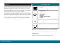
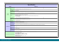
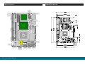
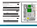
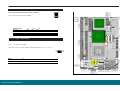
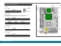
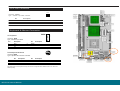
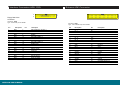
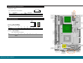
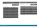
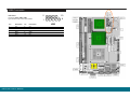
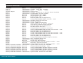
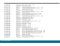
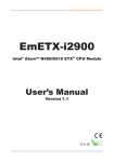
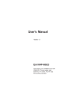
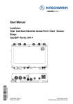
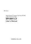
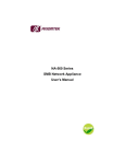
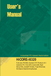
AR-B1740
VER 1.0
CPU TYPE
CPU
mPGA478M
Pentium M
1.7GHz
CHIPSET
MEMORY
I/O
ICH4
Intel 855GME
DDR
1GB
USB/Serial/
IrDA/LPT
LAN
AUDIO
FORM FACTOR
Half-sieze
SBC
PCI
10/100/Gigabit
Mbps
AC'97
IDE x 4
FDD x 2
USER'S MANUAL
Copyright© 2003
All Rights Reserved.
The information in this document is subject to change without prior notice in order to improve
the reliability, design and function.
It does not represent a commitment on the part of the
manufacturer.
Under no circumstances will the manufacturer be liable for any direct, indirect, special,
incidental, or consequen-tial damages arising from the use or inability to use the product or
documentation, even if advised of the possibility of such damages.
This document contains proprietary information protected by copyright. All rights are reserved.
No part of this manual may be reproduced by any mechanical, electronic, or other means in
any form without prior written permission of the manufacturer.
Warning
Single Board Computers and their components contain very delicate Integrated
Circuits (IC). To protect the Single Board Computer and its components against
damage from static electricity, you should always follow the following precautions
when handling it :
1.
Disconnect your Single Board Computer from the power source when you want to work
on the inside
2.
Hold the board by the edges and try not to touch the IC chips, leads or circuitry
3.
Use a grounded wrist strap when handling computer components.
4.
Place components on a grounded antistatic pad or on the bag that came with the Single
Board Computer, whenever components are separated from the system
5. Compact Flash Card is not hot-plug since it uses IDE interface.
About this Manual
This manual provides general information and installation instructions about the board and this
User's Manual is intended for experienced users and integrators with hardware knowledge of
personal computers. If you are not sure about any description in this User's Manual, please
consult your vendor before further handling.
Replacing the lithium battery
Incorrect replacement of the lithium battery may lead to a risk of explosion.
The lithium battery must be replaced with an identical battery or a battery type recommended
by teh manufacturer (BR2335).
Do not throw lithium batteries into the trashcan. It must be disposed of in accordance with
local requlations concerning special waste.
AR-B1740 User's Manual
2
Warranty
PACKING LIST
This product is warranted to be in good working order for a period of one year from the date
of purchase. Should this product fail to be in good working order at any time during this period,
we will, at our option, replace or repair it at no additional charge except as set forth in the
following terms. This warranty does not apply to products damaged by misuse, modifications, accident or disaster.
AR-B1740
Vendor assumes no liability for any damages, lost profits, lost savings or any other incidental
or consequential damage resulting from the use, misuse of, or inability to use this product.
Vendor will not be liable for any claim made by any other related party.
1xPRINT Cable
2xCOM Flat Cable
1xFDD Cable
1xUSB V2.0 Cable
1xAUDIO Cable
1xIDE Cable
1xUltraDMA 100 IDE Flat Cable
1xY Cable
1xCooler
Vendors disclaim all other warranties, either expressed or implied, including but not limited to
implied warranties of merchantibility and fitness for a particular purpose, with respect to the
hardware, the accompanying product's manual(s) and written materials, and any accompanying hardware. This limited warranty gives you specific legal rights.
Return authorization must be obtained from the vendor before returned merchandise will be
accepted. Authorization can be obtained by calling or faxing the vendor and requesting a
Return Merchandise Authorization (RMA) number. Returned goods should always be accompanied by a clear problem description.
1 x CD-ROM (driver)
Before up and running, please make sure the package contains all of above accessories.
If any of the above items is damaged or missing, contact your vendor immediately.
Ordering Codes
AR-B1740
Low power Intel Pentium-M Half size PCI BUS SBC with CRT/LCD & LAN
AR-B1740 User's Manual
3
Specification
MODEL
AR-B1740
SYSTEM
AR-B1740
CPU
mPGA478M socket support: Pentium-M with FSB 400 up to 2.0 GHz
CPU Cache
CPU Integrated
Chipset
Southbridge: ICH4; Northbridge: Intel 855GME
Memory
One 184-pin DIMM sockets support up to 1GB DDR SDRAM (266MHz/333MHz) ECC
Display
Chipset: 855GME integrated graphic, 4 x AGP
Display Memory: Memory shared up to 64MB (DVMT)
Display Type: CRT/ LCD
LVDS panel supported 2 channel 48 bit resolution up to 1600x1200 at 85Hz & 2048x1536 at 75Hz
TTL 24 bit supported
Fast Ethernet
1x Onboard 10/100 Mbps Fast Ethernet (Intel 82562ET PHY)
Audio
ICH4 integrated audio with AC97 Codec
Audio Interactive (MIC in, Line-in, Speaker out, AC'97 ver. 2.3)
Flash Disk
CompactFlash Type II
Serial Port
1 x RS-232C & 1 x RS-232C/422/485
Parallel Port
1 x Parallel prot supports SPP, EPP and ECP mode
Enhanced IDE
2 ports and up to 4 ATAPI devices, Ultra DMA transfer rates 33/66/100MB/sec (IDE1: 40 Pin DMA 100; IDE2: 44 Pin DMA 33)
Floppy
2 floppy disk drives
IrDA
1 x IrDA
USB
6 x USB 2.0 Ports
K/B & Mouse
1 x PS/2 connector for keyboard & mouse
Watchdog Timer
256 level generates RESET
System
Board
Multiple I/O
Mechanical and Environment
AR-B1740 User's Manual
Power Requirement: [email protected], [email protected] (Pentium M 1.7Ghz + 1GB DDR SDRAM)
Power Consumption: TBD
Typical: 18W@5V (1.1GHz LV CPU)
Operating Temperature: 0 ~ 60¢XC (32 ~ 140¢XF)
Storage Temperature: -20 ~ 80¢XC (-68 ~ 176¢XF)
Relative Humidity: 0% ~ 90%
Dimension (Lx W): 185 x 122 mm (7.3" x 4.8")
Weight: 0.6Kg (1.32 Ib)
4
Board Layout
Board Dimension
5
AR-B1740 User's Manual
5
Jumper/Connector quick reference
Jumpers
Jumper/Connector Quick Reference
Connectors
Lable
Function
Lable
Function
JBAT1
Clear CMOS
AUDIO1
Audio Interface Port
JRS2
COM2 RS-232C / 422 / 485 Selection
CFD1
Compact Flash Disk
JVLCD1
LVDS voltage selection
COM1
RS-232C Serial Port
JSMB1
External SMB
COM2
Serial Port (RS-232C/422/485)
JFRT1
Switches & Indicators
CPUF1
CPU Fan connector
J1
CPU Type selection
DIMM1
DDR bank 1/2 184 pin DIMM Socket
EATX1
ATX feature connector
EKB1
External Keyboard Connector
AR-B1740 User's Manual
FDD1
Floppy Disk Drive Connector
IDE1
Primary IDE Connector
IDE2
Secondary IDE Connector
INV1
LCD Inverter Connector
KBM1
Keyboard and PS/2 Mouse
LAN1
10/100 LAN1 Connector
LAN2
10/100/1000 M Connector
LCD1
18bit/24bit TTL Flat Panel Connector (DF13 40 pin)
LVDS1
24bit LVDS Panel Connector (DF13 30 pin)
LPT1
Parallel Port
PWR1
4P Auxiliary Power Connector
IR1
Infrared (IR) Connector
USB1
USB Port 0,1
USB2
USB Port 2,3
USB3
USB Port 4,5
VGA1
VGA Display Connector
6
CMOS Jumper Settings
1
3
CMOS Operation (JBAT1)
2
Type : JBAT1: onboard 3-pin header
If the AR-B1740 refuses to boot due to inappropriate CMOS settings, here is how to
proceed to clear (reset) the CMOS to its default values.
CMOS Setup (JBAT1)
JBAT1
JBAT1
Normal Operation
1-2
ON
Clear CMOS
default setting
2-3
ON
Status
1-2 ON
External SMB
Type : JSMB1: onboard 3-pin header
1
Pin
Description
1
2
3
SMB DATA
SMB CLK
GND
2
LVDS LCD Power Selection
Type : JVLCD1: onboard 3-pin header
The voltage of LCD panel could be selected by JV9 in 5V or 3.3V .
Mode
3.3V
AR-B1740 User's Manual
2
3
JVLCD1
JVLCD1
2-3
5V
default setting
1
1-2
3.3V
7
Serial Port Selection (RS232C/422/485)
RS-232C/422/485 Mode select (JRS2)
Type : JRS2: onboard 6-pin(2*3) header
JRS2 Selection
RS-232C
1-2
ON
3-4
5-6
OFF
OFF
RS-422
OFF
ON
OFF
OFF
OFF
ON
RS-485
default setting
2
4
6
1
3
5
RS-232C
CPU Type Selection
Type : J1: onboard 2-pin header
The CPU VccA (PLL supply voltage) could be selected by J1 in 1.5 V or 1.8
1
2
Mode
J1
CPU
: 1.8V
ON correct setting of CPU VccA before up and running.
Note:VccA
Please
make sure the
CPU VccA : 1.5V
OFF
default setting
AR-B1740 User's Manual
VccA : 1.8 V
8
Switches and Indicators
Reset Button
1 2
Connector : RESET
Pin
Description
1
RESET
2
GND
RESET
PLED
JFRT1
HLED
ESPK
ATX Soft Power Switch
9 10
Power LED Connector
Connector : PLED
Power LED can be indicated when the CPU card is on or off. And keyboard lock can be
used to disable the keyboard function so the PC will not respond by any input.
Pin
Description
3
Power LED+
4
Power LED-
Power LED status description
Power Type
AT Power
Power On
On
ATX Power
On
Power Suspend
Fast Glittering
Fast Glittering
Power Off
Off
Slow Glittering
Hard Disk LED Connector
Connector : HLED
Pin
Description
5
Hard Disk LED+
6
Hard Disk LED-
External Speaker Connector
Connector : ESPK1
Pin
Description
7
+5V
8
Speak out
AR-B1740 User's Manual
9
Audio Interface
Connector : JCOM2
Type : onboard 4-pin box header
9
1
Audio1
Connector : Audio1
Type : Onboard 10-pin box header
Pin
Description
1
3
5
7
9
LINE IN LEFT
GND
MIC
GND
SPEAKER LEFT
Pin
2
4
6
8
4321
10
2
Pin
Description
Pin
Description
1
485DATA+(422TXD+)
2
485DATA-(422TXD-)
3
422RXD+
4
422RXD-
Description
LINE IN RIGHT
GND
NC
GND
10
SPEAKER RIGHT
COM Port Connector
COM1
Connector : COM1
Type : onboard 10-pin box header
Pin
Description
Pin
1
DCD
2
RXD
3
TXD
4
DTR
5
GND
6
DSR
7
RTS
8
CTS
9
RI
Connector : COM2
Type : onboard 10-pin box header
Pin
COM2
Description
Pin
1
DCD2
2
RXD2
3
TXD2
4
DTR2
5
GND
6
DSR2
7
RTS2
8
CTS2
9
RI
10
NC
AR-B1740 User's Manual
Description
Description
10
CPU Fan Connector
123
Connector : CPUF1
Type : onboard 3-pin wafer connector
Pin
Description
1
GND
2
+12V
3
FAN Dectect
CPUF1
Keyboard & Mouse Connector
1
2
3
4
5
EKB1
AT Keyboard
Connector : EKB1
Type : Onboard 5-pin header
Pin
Description
1
3
5
CLK
NC
Vcc
Pin
2
4
Description
DATA
GND
3
1
PS/2 Keyboard & Mouse
5
6
Connector: KBM1
Type: 6-pin Mini DIN connector on bracket
2
Pin
Description
Pin
Description
1
3
5
KB-DATA
GND
KB-CLK
2
4
MS-DATA
VCC
6
MS-CLK
Note: KBM1 supports PS/2 keyboard directly, and PS/2 mouse suppoted with the additional PS2 1-to-2 cable in the
standard packing.
AR-B1740 User's Manual
11
Interface Connectors HDD, FDD
Enhance IDE Connector
Interface Connectors HDD, FDD
33
34
1
2
1
2
Floppy Disk Drive
Connector
Connector : FDD1
Type : onboard 34-pin box header
Pin
1
Description
GND
Pin
2
Connector : IDE1
Type : Two onboard 40-pin box headers
Pin
Description
Pin
Description
DRIVE DENSITY SELECT 0
1
#RESET
2
GND
D7 4
D8
Description
3
GND
4
NC
3
5
GND
6
DRIVE DENSITY SELECT 1
5
D6 6
D9
D5 8
D10
7
GND
8
#INDEX
7
9
GND
10
#MOTOR ENABLE A
9
D4 10
D11
D3 12
D12
11
GND
12
#DRIVER SELECT B
11
13
GND
14
#DRIVER SELECT A
13
D2 14
D13
#MOTOR ENABLE B
15
D1 16
D14
#DIRECTION
17
D0 18
D15
#STEP
19
GND
20
NC/(Vcc)
REQ
22
GND
15
17
19
GND
GND
GND
16
18
20
21
GND
22
#WRITE DATA
21
23
GND
24
#WRITE GATE
23
#IOW
24
GND
#IOR
26
GND
25
GND
26
#TRACK 0
25
27
GND
28
#WRITE PROTECT
27
#IORDY
28
IDESEL
#DACK
30
GND
29
GND
30
#READ DATA
29
31
GND
32
#HEAD SELECT
31
IRQ
32
NC (-IOCS16)
#DISK CHANGE
33
ADDR1
34
CBLID
33
GND
AR-B1740 User's Manual
34
35
ADDR0
36
ADDR2
37
#CS1
38
#CS3(#HD SELECT1)
39
#ACT
40
GND
12
Enhance IDE Connector
Peripheral Port
1
2
Connector : IDE2
Type : One onboard 44-pin box headers
Connector : LPT1
Type : onboard 26-pin box header
25
26
1
2
LPT1
Pin
Description
Pin
Description
Pin
Description
Pin
Description
1
#RESET
2
GND
1
#STROBE
2
#AUTO FEED
3
D7 4
D8
3
DATA0
4
#ERROR
5
D6 6
D9
5
DATA1
6
#INITIALIZE
7
D5 8
D10
7
DATA2
8
#SELECT INPUT
9
D4 10
D11
9
DATA3
10
GND
11
D3 12
D12
11
DATA4
12
GND
13
D2 14
D13
13
DATA5
14
GND
15
D1 16
D14
15
DATA6
16
GND
17
D0 18
D15
17
DATA7
18
GND
19
GND
20
NC
19
#ACKNOWLEDGE
20
GND
21
REQ
22
GND
21
BUSY
22
23
#IOW
24
GND
22
PAPER EMPTY
24
GND
25
#IOR
26
GND
25
SELECT
26
GND
27
#IORDY
28
IDESEL
29
#DACK
30
GND
31
IRQ
32
NC (-IOCS16)
33
ADDR1
34
CBLID
35
ADDR0
36
ADDR2
37
#CS1
38
#CS3(#HD SELECT1)
39
#ACT
40
GND
41
Vcc 42
Vcc
43
GND
44
AR-B1740 User's Manual
GND
NC
13
LCD Inverter connector
Connector : INV1
1 2 3 4 5
Type : Onboard 5-pin mini boxheader
Pin
Description
1
3
+12 V
on/off
5
Pin
2
4
Description
GND
brightness control
GND
LAN connector
LAN1
LAN ConnectLAN Port
1
2
3
4
5
6
7
8
Connector : LAN1(10/100Mbps)
Type : external RJ-45 on bracket
Pin
1
Desciption
2
3
4
5
6
7
8
TX+
TX-
RX+
NC
NC
RX-
NC NC
4
5
6
7
8
Connector : LAN2(1000Mbps)
Type : external RJ-45 on bracket
Pin
1
Desciption
2
3
MDX0+ MDX0- MDX1+ MDX2+ MDX2- MDX1- MDX3+
MDX3-
AR-B1740 User's Manual
14
18/24bit TTL Flat Panel Connector
Connector : LCD1
Type : Onboard DF13 40-pin
LVDS LCD Connector
39
1
1
29
2
30
Connector LVDS1
Type : onboard 30-pin DF-13 Connector
2
LCD1
LCD1 pin Assignment
Pin
1
3
5
7
9
11
13
15
17
19
21
23
25
27
29
31
33
35
37
39
Description
VDD
Ground
VDD
NA
R0
R2
R4
R6
G0
G2
G4
G6
B0
B2
B4
B6
Ground
FPSCLK
DTMG
NA
Pin
2
4
6
8
10
12
14
16
18
20
22
24
26
28
30
32
34
36
38
40
Description
VDD
Ground
VDD
Ground
R1
R3
R5
R7
G1
G3
G5
G7
B1
B3
B5
B7
Ground
VS
HS
NA
40
Pin
Signal
Pin
Signal
1
VDD
2
VDD
3
TX1CLK+
4
TX2CLK+
5
TX1CLK-
6
TX2CLK-
7
GND
8
GND
9
TX1D0+
10
TX2D0+
11
TX1D0-
12
TX2D0-
13
GND
14
GND
15
TX1D1+
16
TX2D1+
17
TX1D1-
18
TX2D1-
19
GND
20
GND
21
TX1D2+
22
TX2D2+
23
TX1D2-
24
TX2D2-
25
GND
26
GND
27
TX1D3+
28
TX2D3+
29
TX1D3-
30
TX2D3-
Note: VDD Voltage selected by JVLCD1 in 5V or 3.3V.
Note: VDD Voltage selected by JVLCD1 in 5V or 3.3V.
AR-B1740 User's Manual
15
Power Connector
PWR1
fer connector
Pin
+5 V
GND
GND
+12 V
Description
1
+5V
2
GND
3
GND
4
+12V
Infrared (IR) Connector
Infrared (IR) Connector
Connector : IR1
1 2 3 4 5
Type : onboard 5-pin header
Pin
Description
Pin
Description
1
3
Vcc
IRRX
2
4
NC
GND
5
IRTX
VGA Connector
6
VGA1
Connector : VGA1
Type : external 15-pin D-sub female connector
11
12
13
14
15
1
2
3
4
5
10
Pin Description
Description
GND
11 NC
RED
2
GREEN
7
GND
12 VDDAT
3
BLUE
8
GND
13 HSYNC
4
NC
9
Vcc
14 VSYNC
5
GND
10
GND
15 VDCLK
AR-B1740 User's Manual
6
Pin
1
Pin Description
16
USB Connector
USB Ports
2
10
Connector: USB1, USB2, USB3
Type:onboard 2*5pin 2.0mm pitch header
1
9
Pin
Description
Pin
Description
1
Vcc
2
Vcc
3
DATA-
4
DATA-
5
DATA+
6
DATA+
7
GND
8
GND
9
GND
10
Key
AR-B1740 User's Manual
USB
17
System Resources
Resource
DMA 02
DMA 04
controller IRQ 00
IRQ 01
IRQ 02
IRQ 03
IRQ 04
IRQ 05
IRQ 05
IRQ 05
IRQ 06
IRQ 07
IRQ 08
IRQ 09
IRQ 09
IRQ 09
IRQ 09
IRQ 0A
IRQ 0A
IRQ 0A
IRQ 0A
IRQ 0B
IRQ 0B
IRQ 0B
IRQ 0B
IRQ 0B
IRQ 0C
IRQ 0D
IRQ 0E
IRQ 0E
IRQ 0F
IRQ 0F
Memory 00000000-0009FFFF
Memory 00000000-FFFFFFFF
Memory 000A0000-000AFFFF
Memory 000B0000-000BFFFF
Memory 000C0000-000CC7FF
Memory 000D0000-000D17FF
Memory 000D1800-000D3FFF
AR-B1740 User's Manual
Share
Undetermined
Undetermined
Undetermined
Undetermined
Undetermined
Exclusive
Exclusive
Shared
Shared
Shared
Undetermined
Undetermined
Undetermined
Shared
Shared
Shared
Shared
Shared
Shared
Shared
Shared
Shared
Shared
Shared
Shared
Shared
Undetermined
Undetermined
Exclusive
Undetermined
Exclusive
Undetermined
Undetermined
Exclusive
Exclusive
Exclusive
Exclusive
Exclusive
Undetermined
Device Description
Standard Floppy Disk Controller
Direct
memory
access
System timer
Standard 101/102-Key or Microsoft Natural Keyboard
Programmable interrupt controller
Communications Port (COM2)
Communications Port (COM1)
Realtek AC’97 Audio
ACPI IRQ Holder for PCI IRQ Steering
Intel(R) 82801DB/DBM SMBus Controller - 24C3
Standard Floppy Disk Controller
Printer Port (LPT1)
System CMOS/real time clock
Intel(R) PRO/1000 MT Network Connection
Intel USB 2.0 Enhanced Host Controller
ACPI IRQ Holder for PCI IRQ Steering
SCI IRQ used by ACPI bus
Intel(R) PRO/100 VE Network Connection
Intel(R) 82801DB/DBM USB Universal Host Controller - 24C4
ACPI IRQ Holder for PCI IRQ Steering
ACPI IRQ Holder for PCI IRQ Steering
Intel(R) 82801DB/DBM USB Universal Host Controller - 24C2
Intel(R) 82801DB/DBM USB Universal Host Controller - 24C7
ACPI IRQ Holder for PCI IRQ Steering
ACPI IRQ Holder for PCI IRQ Steering
Intel(R) 82852/82855 GM/GME Graphics Controller
PS/2 Compatible Mouse Port
Numeric data processor
Primary Ultra ATA Controller
Intel(R) 82801DB Ultra ATA Storage Controller - 24CB
Secondary Ultra ATA Controller
Intel(R) 82801DB Ultra ATA Storage Controller - 24CB
System board extension for ACPI BIOS
Intel(R) 82801DB PCI Bridge - 244E
Intel(R) 82852/82855 GM/GME Graphics Controller
Intel(R) 82852/82855 GM/GME Graphics Controller
Intel(R) 82852/82855 GM/GME Graphics Controller
Intel(R) PRO/100 VE Network Connection
System board extension for ACPI BIOS
18
Memory 000E0000-000EFFFF
Memory 000F0000-000F7FFF
Memory 000F8000-000FBFFF
Memory 000FC000-000FFFFF
Memory 00100000-1DFEFFFF
Memory 1DFF0000-1DFFFFFF
Memory D0000000-D7FFFFFF
Memory D8000000-DFFFFFFF
Memory E0000000-E1FFFFFF
Memory E1000000-E101FFFF
Memory E1020000-E102FFFF
Memory E1030000-E1030FFF
Memory E2000000-E207FFFF
Memory E2080000-E20FFFFF
Memory E2100000-E21003FF
Memory E2101000-E21011FF
Memory E2102000-E21020FF
Memory FEC00000-FECFFFFF
Memory FEE00000-FEEFFFFF
Memory FFB00000-FFB7FFFF
Memory FFB80000-FFBFFFFF
Memory FFF00000-FFFFFFFF
Port 0000-000F
Port 0010-001F
Port 0020-0021
Port 0022-003F
Port 0040-0043
Port 0044-005F
Port 0060-0060
Port 0061-0061
Port 0062-0063
Port 0064-0064
Port 0065-006F
Port 0070-0073
Port 0074-007F
Port 0080-0090
Port 0091-0093
Port 0094-009F
Port 00A0-00A1
Port 00A2-00BF
AR-B1740 User's Manual
Undetermined
Undetermined
Undetermined
Undetermined
Undetermined
Undetermined
Exclusive
Exclusive
Exclusive
Exclusive
Exclusive
Exclusive
Exclusive
Exclusive
Exclusive
Exclusive
Exclusive
Undetermined
Undetermined
Undetermined
Undetermined
Undetermined
Undetermined
Undetermined
Undetermined
Undetermined
Undetermined
Undetermined
Undetermined
Undetermined
Undetermined
Undetermined
Undetermined
Undetermined
Undetermined
Undetermined
Undetermined
Undetermined
Undetermined
Undetermined
System board extension for ACPI BIOS
System board extension for ACPI BIOS
System board extension for ACPI BIOS
System board extension for ACPI BIOS
System board extension for ACPI BIOS
System board extension for ACPI BIOS
Intel(R) 82852/82855 GM/GME Graphics Controller
Intel(R) 82852/82855 GM/GME Graphics Controller
Intel(R) 82801DB PCI Bridge - 244E
Intel(R) PRO/1000 MT Network Connection
Intel(R) PRO/1000 MT Network Connection
Intel(R) PRO/100 VE Network Connection
Intel(R) 82852/82855 GM/GME Graphics Controller
Intel(R) 82852/82855 GM/GME Graphics Controller
Intel USB 2.0 Enhanced Host Controller
Realtek AC’97 Audio
Realtek AC’97 Audio
System board extension for ACPI BIOS
System board extension for ACPI BIOS
System board extension for ACPI BIOS
Intel(r) 82802 Firmware Hub Device
System board extension for ACPI BIOS
Direct memory access controller
Motherboard resources
Programmable interrupt controller
Motherboard resources
System timer
Motherboard resources
Standard 101/102-Key or Microsoft Natural Keyboard
System speaker
Motherboard resources
Standard 101/102-Key or Microsoft Natural Keyboard
Motherboard resources
System CMOS/real time clock
Motherboard resources
Direct memory access controller
Motherboard resources
Direct memory access controller
Programmable interrupt controller
Motherboard resources
19
Port
Port
Port
Port
Port
Port
Port
Port
Port
Port
Port
Port
Port
Port
Port
Port
Port
Port
Port
Port
Port
Port
Port
Port
Port
Port
Port
Port
Port
Port
Port
Port
Port
Port
Port
Port
Port
Port
Port
Port
Port
00C0-00DF
00E0-00EF
00F0-00FF
0170-0177
0170-0177
01F0-01F7
01F0-01F7
02F8-02FF
0376-0376
0376-0376
0378-037F
03B0-03BB
03C0-03DF
03F0-03F5
03F6-03F6
03F6-03F6
03F7-03F7
03F8-03FF
0400-04BF
04D0-04D1
0500-051F
0778-077B
0A78-0A7B
0B78-0B7B
0BBC-0BBF
0CF8-0CFF
0E78-0E7B
0F78-0F7B
0FBC-0FBF
9000-903F
9000-9FFF
9400-943F
A000-A01F
A400-A41F
A800-A81F
AC00-AC07
B400-B4FF
B800-B83F
F000-F007
F000-F00F
F008-F00F
AR-B1740 User's Manual
Undetermined
Undetermined
Undetermined
Exclusive
Exclusive
Exclusive
Exclusive
Undetermined
Exclusive
Exclusive
Undetermined
Exclusive
Exclusive
Undetermined
Exclusive
Exclusive
Undetermined
Undetermined
Undetermined
Undetermined
Exclusive
Undetermined
Undetermined
Undetermined
Undetermined
Undetermined
Undetermined
Undetermined
Undetermined
Exclusive
Exclusive
Exclusive
Exclusive
Exclusive
Exclusive
Exclusive
Exclusive
Exclusive
Undetermined
Exclusive
Undetermined
Direct memory access controller
Motherboard resources
Numeric data processor
Intel(R) 82801DB Ultra ATA Storage Controller - 24CB
Secondary Ultra ATA Controller
Intel(R) 82801DB Ultra ATA Storage Controller - 24CB
Primary Ultra ATA Controller
Communications Port (COM2)
Intel(R) 82801DB Ultra ATA Storage Controller - 24CB
Secondary Ultra ATA Controller
Printer Port (LPT1)
Intel(R) 82852/82855 GM/GME Graphics Controller
Intel(R) 82852/82855 GM/GME Graphics Controller
Standard Floppy Disk Controller
Intel(R) 82801DB Ultra ATA Storage Controller - 24CB
Primary Ultra ATA Controller
Standard Floppy Disk Controller
Communications Port (COM1)
Motherboard resources
Motherboard resources
Intel(R) 82801DB/DBM SMBus Controller - 24C3
Printer Port (LPT1)
Motherboard resources
Motherboard resources
Motherboard resources
PCI bus
Motherboard resources
Motherboard resources
Motherboard resources
Intel(R) PRO/1000 MT Network Connection
Intel(R) 82801DB PCI Bridge - 244E
Intel(R) PRO/100 VE Network Connection
Intel(R) 82801DB/DBM USB Universal Host Controller - 24C2
Intel(R) 82801DB/DBM USB Universal Host Controller - 24C4
Intel(R) 82801DB/DBM USB Universal Host Controller - 24C7
Intel(R) 82852/82855 GM/GME Graphics Controller
Realtek AC’97 Audio
Realtek AC’97 Audio
Primary Ultra ATA Controller
Intel(R) 82801DB Ultra ATA Storage Controller - 24CB
Secondary Ultra ATA Controller
20
CPU Heatsink Installation
To install CPU heatsink,
please be aware of the
orientation of it. Align the end
of CPU Fan power cable to
the top-left in order to mount
it easily.
The solided side
of heatsink that
to be secured by
screws
CPU Fan power
socket
Use tool-free
screws to secure
heatsink
The holes
that secure
the heatsink
Warning:
Insert the CPU
fan powe cable
into the socket
and place the
heatsink into
position.
AR-B1740 User's Manual
Screw them to
half-way at the
same time, then
screw each of
them until
heatsink snaps
into mainboard
gently.
21
AWARD BIOS Setup
The AR-B1740 uses the Award PCI/ISA BIOS for the system configuration.
The Award BIOS setup program is designed to provide the maximum flexibility in configuring
the system by offering various options which could be selected for end-user requirements.
This chapter is written to assist you in the proper usage of these features.
To access AWARD PCI/ISA BIOS Setup program, press <Del> key. The Main Menu will be
displayed at this time.
Setup Items
The main menu includes the following main setup categories.
may not include all entries.
Recall that some systems
Standard CMOS Features
Use this menu for basic system configuration.
Advanced BIOS Features
Use this menu to set the Advanced Features available on your system.
Advanced Chipset Features
Use this menu to change the values in the chipset registers and optimize your system's
performance.
Integrated Peripherals
Use this menu to specify your settings for integrated peripherals.
Power Management Setup
Use this menu to specify your settings for power management.
PnP / PCI Configuration
This entry appears if your system supports PnP / PCI.
PC Health Status
This entry helps you to monitor the status of PC.
Frequency/Voltage Control
Use this menu to specify your settings for frequency/voltage control.
Load Optimized Defaults
Use this menu to load the BIOS default values that are factory settings for optimal
performance system operations.
While Award has designed the custom BIOS to
maximize performance, the factory has the right to change these defaults to meet their
needs.
Once you enter the AwardBIOS™ CMOS Setup Utility, the Main Menu will appear on the screen.
The Main Menu allows you to select from several setup functions and two exit choices.
Use
the arrow keys to select among the items and press <Enter> to accept and enter the sub- menu.
Set Password
Use this menu to set User and Supervisor Passwords.
Save & Exit Setup
Save CMOS value changes to CMOS and exit setup.
Exit Without Save
Abandon all CMOS value changes and exit setup.
AR-B1740 User's Manual
22
Standard CMOS Setup
Video Select the type of primary video subsystem in your computer. The BIOS usually
detects the correct video type automatically. The BIOS supports a secondary video subsystem, but you do not select it in Setup.
Halt On During the power-on self-test (POST), the computer stops if the BIOS detects a
hardware error. You can tell the BIOS to ignore certain errors during POST and continue the
boot-up process. These are the selections:
No errors
POST does not stop for any errors.
All errors
If the BIOS detects any non-fatal error, POST stops and prompts you to
take corrective action.
All, But Keyboard
POST does not stop for a keyboard error, but stops for all other errors.
All, But Diskette
POST does not stop for diskette drive errors, but stops for all other
errors.
All, But Disk/Key
POST does not stop for a keyboard or disk error, but stops for all other
errors.
Date
The BIOS determines the day of the week from the other date information; this field is for
information only.
Time
The time format is based on the 24-hour military-time clock. For example, 1 p.m. is 13:00:00.
Press the PgUp or PgDn key to
Press the « or ( key to move to the desired field .
increment the setting, or type the desired value into the field.
IDE Primary Master/Slave
IDE Secondary Master/Slave
Options are in sub menu
Drive A, B
Select the correct specifications for the diskette drive(s) installed in the computer.
None :
360K ;
1.2M ;
720K ;
1.44M ;
2.88M ;
AR-B1740 User's Manual
No diskette drive installed
5.25 in 5-1/4 inch PC-type standard drive
5.25 in 5-1/4 inch AT-type high-density drive
3.5 in 3-1/2 inch double-sided drive
3.5 in 3-1/2 inch double-sided drive
3.5 in 3-1/2 inch double-sided drive
23
BIOS Features Setup
CPU L1 & L2 Cache
Cache memory is additional memory that is much faster than conventional DRAM (system
memory). CPUs from 486-type on up contain internal cache memory, and most, but not all,
CPU L3 Cache
This item allows you to enable/disable CPU L3 Cache.
The choice: Enabled, Disabled.
Quick Power On Self Test
This category speeds up Power On Self Test (POST) after you power up the computer.
If it is set to Enable, BIOS will shorten or skip some check items during POST. Enabled :
Enable quick POST. Disabled : Normal POST
First/Second/Third/Other Boot Device
The BIOS attempts to load the operating system from the devices in the sequence selected
in these items. The choices are : Floppy, LS/ZIP, HDD, SCSI, CDROM, Disabled.
Swap Floppy Drive
If the system has two floppy drives, you can swap the logical drive name assignments.
The choice: Enabled/Disabled.
Boot Up Floppy Seek
Seeks disk drives during boot up.
The choice: Enabled/Disabled.
Disabling speeds boot up.
Boot Up NumLock Status
Select power on state for NumLock. The choice: Enabled/Disabled.
Virus Warning
Allows you to choose the VIRUS Warning feature for IDE Hard Disk boot sector protection.
If this function is enabled and someone attempt to write data into this area, BIOS will show a
warning message on screen and beep.
Enabled
Activates automatically when the system boots up causing a warning message to
appear when anything attempts to access the boot sector or hard disk partition
table.
Disabled No warning message will appear when anything attempts to access the boot
sector or hard disk partition table.
AR-B1740 User's Manual
Gate A20 Option
Select if chipset or keyboard controller should control GateA20.
Normal A pin in the keyboard controller controls GateA20
Fast
Lets chipset control GateA20
Typematic Rate Setting
Keys t r o k e s repeat at a rate determined by the keyboard controller.
the typematic rate and typematic delay can be selected.
The choice: Enabled/Disabled.
When enabled,
24
Advanced Chipset Features
Security Option
Select whether the password is required every time the system boots or only when you
enter setup.
System
The system will not boot and access to Setup will be denied if the correct
password is not entered at the prompt.
Setup
The system will boot, but access to Setup will be denied if the correct password is
not entered at the prompt.
Note
To disable security, select PASSWORD SETTING at Main Menu and then you will be
asked to enter password.
Do not type anything and just press <Enter>, it will
disable security.
Once the security is disabled, the system will boot and you can
enter Setup freely.
APIC Mode
Setting it to Enabled is to extend the number of IRQ.
OS Select For DRAM > 64MB
Select the operating system that is running with greater than 64MB of RAM on the system. The
choice: Non-OS2, OS2.
Small Logo(EPA) Show
[Enabled]: If you want to show your logo, please enable it.
[Disabled]: When this item disabled, logo(EPA) will not show on screen.
DRAM Timing Selectable
When synchronous DRAM is installed, the number of clock cycles of CAS latency depends
on DRAM timing.
The choices: By SPD (default), Manual
CAS Latency Time
When synchronous DRAM is installed, the number of clock cycles of CAS latency depends
on the DRAM timing. Do not reset this field from the default value specified by the system
designer.
Active to Precharge Delay
Delay that results when two different rows in a memory chip are addressed one after
another.
DRAM RAS# to CAS# Delay
When RAS is asserted, there must be a small wait before the CAS can be pulled. This setting
controls length of the wait. Like CAS latency, it's a delay before you get your data, so while
your system is faster at a lower setting, it's also more stressful at that setting. Your RAM
may handle it, or it may not.
AR-B1740 User's Manual
25
DRAM RAS Precharge
The third part of the x-y-z notation used in SDRAM, the other two being CAS and RAS to
CAS. Like its brethren, it's better lower but also more stressful lower. See the pattern 2.5 is
only available with DDR.
On-Chip VGA
If your system contains a VGA controller and you want to activate it, select Enabled. The
next option will become available.
DRAM Data Integrity Mode
This BIOS feature controls the ECC feature of the memory controller.
On-Chip Frame Buffer Size
The On-Chip Frame Buffer Size can be set to 1MB or 8MB. This memory is shared with
system memory.
System BIOS Cacheable
Allows the system BIOS to be cached for faster system performance.
Boot Display
This option let you select the display devices.
Video BIOS Cacheable
This item allows you to "Enabled" or "Disabled" on Video BIOS Cacheable.
Panel Number
This option let you select the type of panel.
Memory Hole At 15M-16M
If you enable this feature, 1MB of memory (the 15th MB) will be reserved exclusively for the ISA
card's use. This effectively reduces the total amount of memory available to the operating
system by 1MB. If you disable this feature, the 15th MB of RAM will not be reserved for the ISA
card's use. The full range of memory is therefore available for the operating system to use.
However, if your ISA card requires the use of that memory area, it may then fail to work.
Delayed Transaction
The chipset has an embedded 32-bit posted write buffer to support delay transactions cycles.
Select Enabled to support compliance with PCI specification version 2.1.
Delay Prior to Thermal
Controls the activation of the Thermal Monitor's automatic mode. It allows you to determine when
the Pentium 4's Thermal Monitor should be activated in automatic mode after the system boots.
For example, with the default value of 16 Minutes, the BIOS activates the Thermal Monitor in
automatic mode 16 minutes after the system starts booting up.
AGP Aperture Size
Options : 4, 8, 16, 32, 64, 128, 256
This option selects the size of the AGP aperture. The aperture is a portion of the PCI memory
address range dedicated as graphics memory address space. Host cycles that hit the aperture
range are forwarded to the AGP without need for translation. This size also determines the
maximum amount of system RAM that can be allocated to the graphics card for texture storage.
AGP Aperture size is set by the formula : maximum usable AGP memory size x 2 plus 12MB.
That means that usable AGP memory size is less than half of the AGP aperture size. That's
because the system needs AGP memory (uncached) plus an equal amount of write combined
memory area and an additional 12MB for virtual addressing. This is address space, not
physical memory used. The physical memory is allocated and released as needed only when
Direct3D makes a "create non-local surface" call.
AR-B1740 User's Manual
26
Integrated Peripherals
OnChip Primary/Seconary IDE
Select "Enabled" to activate each on-board IDE channel separately, Select "Disabled", if you
install an add-on IDE Control card
IDE HDD Block Mode
This feature enhances disk performance by allowing multi-sector data transfers and eliminates
the interrupt handling time for each sector.
[Sub Menu]
[Sub Menu]
USB Controller
Select "Enabled" to activate USB Controller, Select "Disabled", if you want to disable USB
Controller.
USB 2.0 Controller
Select "Enabled" to activate USB 2.0 Controller, Select "Disabled", if you want to disable USB
2.0 Controller.
USB Keyboard Support
Select Enabled if your system contains a Universal Serial Bus (USB) controller and you have
a USB keyboard.
USB Mouse Support
Select Enabled if your system contains a Universal Serial Bus (USB) controller and you have
a USB mouse.
AR-B1740 User's Manual
27
Power Management Setup
AC97 Audio
AC97 Audio selection.
Init Display First
Select "AGP" or "PCI Slot" for system to detect first when boot-up.
Onboard LAN 1 & 2
Select "Enabled" if your system contains onboard LAN 1 & 2 supports.
Power-Supply Type
Select the power-supply type.
Power
Management
There are 4 selections for Power Management, 3 of which have fixed mode :
Disabled (default)
No power management. Disables all four modes.
Min. Power Saving
Minimum power management. Doze Mode = 1 hr.,
Standby Mode = 1 hr., Suspend Mode = 1 hr.,
Max. Power Saving
Maximum power management -- ONLY AVAILABLE FOR SL CPU's.. Doze
Mode = 1 min., Standby Mode = 1 min., Suspend Mode = 1 min.
User Defined
Allows you to set each mode individually. When not disabled, each of
the ranges are from 1 min. to 1 hr.
HDD Power Down is always set independently
AR-B1740 User's Manual
28
PC Health Status
Video Off Option
Controls what causes the display to be switched off
Suspend -> Off
Always On
All Mode -> Off
Video Off In Suspend
Controls what causes the display to be switched off
Suspend -> Off
Always On
All Mode -> Off
Suspend Type
S1 (POS) Power On suspend
All devices are powered up except for the clock synthesizer. The Host and PCI clocks are
inactive and PIIX4 provides control signals and 32-kHz Suspend Clock (SUSCLK) to allow for
DRAM refresh and to turn off the clock synthesizer. The only power consumed in the system
is due to DRAM Refresh and leakage current of the powered devices. When the system
resumes from POS, PIIX4 can optionally resume without resetting the system, can reset the
processor only, or can reset the entire system. When no reset is performed, PIIX4 only needs
to wait for the clock synthesizer and processor PLLs to lock before the system is resumed.
This takes typically 20 ms.
S3 (STR) Suspend To RAM
Power is removed from most of the system components during STR, except the DRAM.
Power is supplied to Suspend Refresh logic in the Host Controller, and RTC and Suspend Well
logic in PIIX4. PIIX4 provides control signals and 32-kHz Suspend Clock (SUSCLK) to allow for
DRAM refresh and to turn off the clock synthesizer and other power planes.
Modem Use IRQ
Name the interrupt request (IRQ) assigned to the modem (if any) on your system. Activity of
the selected IRQ always awakens the system.
Primary IDE 0/1
Select "Disabled" to turn off Primary IDE.
Secondary IDE 0/1
Select
"Disabled" to turn off Secondary IDE.
This section describes CPU temperare for the system.
Shutdown Temperature
This item allows you to set up the CPU shutdown Temperature. This item only effective
under windows 98 ACPI mode.
System Temperature
This field displays the current system temperature.
CPU Temperature
These fields display the current CPU temperature, if your computer contains a monitoring
system.
FDD,COM,LPT Port
Select
"Disabled" to turn off these I/O.
Vcore
These fields display the current voltage of up to seven voltage input lines, if your computer
contiains a monitoring system.
PCI PIRQ[A-Q]#
Enabled or Disabled PCI,PIRQ[A-D]#IRQ status.
VTT
One type of CPU voltage
+3.3V, +5V, +12V
Show you the voltage of +3.3V, +5V, +12V
CPUFAN Speed
These fields display the current speed of up to three CPU fans, if your computer contains a
monitoring system.
System FAN Speed
Show you the current SystemFAN operating speed
AR-B1740 User's Manual
29
Frequency/Voltage Control
POST Codes
The following codes are not displayed on the screen. They can only be viewed on the LED
display of a so called POST card. The codes are listened in the same order as the according
functions are executed at PC startup. If you have access to a POST Card reader, you can
watch the system perform each test by the value that's displayed. If the system hangs (if
there's a problem) the last value displayed will give you a good idea where and what went
wrong, or what's bad on the system board.
CODE
DESCRIPTION OF CHECK
CFh
Test CMOS R/W functionality.
C0h
Early chipset initialization:
-Disable shadow RAM
-Disable L2 cache (socket 7 or below)
-Program basic chipset registers
C1h
Detect memory
-Auto-detection of DRAM size, type and ECC.
-Auto-detection of L2 cache (socket 7 or below)
Expand compressed BIOS code to DRAM
C3h
C5h
Call chipset hook to copy BIOS back to E000 & F000
shadow RAM.
0h1
Expand the Xgroup codes locating in physical address 1000:0
This section describes Frequency and Voltage control for the system.
02h
Reserved
Auto Detect DIMM/PCI CLK
When enabled, this item will auto detect if the DIMM and PCI socket have devices and will
send clock signal to DIMM and PCI devices. When disabled, it will send the clock signal to all
DIMM and PCI socket.
03h
Initial Superio_Early_Init switch.
04h
Reserved
05h
1. Blank out screen
2. Clear CMOS error flag
06h
Reserved
07h
1. Clear 8042 interface
2. Initialize 8042 self-test
08h
1. Test special keyboard controller for Winbond 977
series Super I/O chips.
2. Enable keyboard interface.
09h
Reserved
Spread Spectrum
This item allows you to enable/disable the spread spectrum modulate.
AR-B1740 User's Manual
30
0Ah
1. Disable PS/2 mouse interface (optional).
2. Auto detect ports for keyboard & mouse followed by a
port & interface swap (optional).
3. Reset keyboard for Winbond 977 series Super I/O chips.
1Fh
Load keyboard matrix (notebook platform)
20h
Reserved
21h
HPM initialization (notebook platform)
0Bh
Reserved
22h
Reserved
0Ch
Reserved
23h
0Dh
Reserved
0Eh
Test F000h segment shadow to see whether it is R/W-able or not. If test fails,
keep beeping the speaker.
1. Check validity of RTC value: e.g. a value of 5Ah is an invalid value for
RTC minute.
2. Load CMOS settings into BIOS stack. If CMOS checksum fails, use default
value instead.
24h
Prepare BIOS resource map for PCI & PnP use. If ESCD is valid, take
into consideration of the ESCD's legacy information.
25h
Early PCI Initialization:
-Enumerate PCI bus number.
-Assign memory & I/O resource
-Search for a valid VGA device & VGA BIOS,
and put it into C000:0
26h
1. If Early_Init_Onboard_Generator is not defined Onboard
clock generator initialization. Disable respective clock
resource to empty PCI & DIMM slots.
2. Init onboard PWM
3. Init onboard H/W monitor devices
0Fh
Reserved
10h
Auto detect flash type to load appropriate flash R/W codes into the run time
area in F000 for ESCD & DMI support.
11h
Reserved
12h
Use walking 1's algorithm to check out interface in CMOS
circuitry.
set real-time clock power status, and then check
for override.
13h
Reserved
14h
Program chipset default values into chipset.
MODBINable by OEM customers.
15h
Reserved
16h
Initial onboard clock generator if Early_Init_Onboard_Generator
See also POST 26h.
17h
Reserved
18h
Detect CPU information including brand, SMI type (Cyrix or
(586 or 686).
19h
Reserved
1Ah
1Bh
1Ch
Reserved
1Dh
Initial EARLY_PM_INIT switch.
1Eh
Reserved
Chipset default
Also
values are
27h
Initialize INT 09 buffer
28h
Reserved
29h
1. Program CPU internal MTRR (P6 & PII)
for 0-640K memory address.
2. Initialize the APIC for Pentium class CPU.
3. Program early chipset according to CMOS setup.
Example: onboard IDE controller.
4. Measure CPU speed.
Reserved
2Ah
Reserved
Initial interrupts vector table.
If no special specified, all H/W
interrupts are
directed to SPURIOUS_INT_HDLR & S/W interrupts to SPURIOUS_soft_HDLR.
2Bh
Invoke Video BIOS
AR-B1740 User's Manual
is defined.
Intel) and CPU level
2Ch
Reserved
2Dh
1. Initialize double-byte language font (Optional)
2. Put information on screen display, including Award title,
31
CPU type, CPU speed, full screen logo.
2Eh
Reserved
2Fh
Reserved
30h
Reserved
31h
Reserved
32h
Reserved
33h
Reset keyboard if Early_Reset_KB is defined e.g. Winbond 977
O chips. See also POST 63h.
34h
Reserved
35h
Test DMA Channel 0
36h
Reserved
37h
Test DMA Channel 1.
38h
Reserved
39h
Test DMA page registers.
3Ah
Reserved
3Bh
Reserved
3Ch
Test 8254
3Dh
Reserved
3Eh
Test 8259 interrupt mask bits for channel 1.
series Super I/
48h
Reserved
49h
1. Calculate total memory by testing the last double
word of each 64K page.
2. Program write allocation for AMD K5 CPU.
4Ah
Reserved
4Bh
Reserved
4Ch
Reserved
4Dh
Reserved
4Eh
1. Program MTRR of M1 CPU
2. Initialize L2 cache for P6 class CPU & program
CPU with proper cacheable range.
3. Initialize the APIC for P6 class CPU.
4. On MP platform, adjust the cacheable range to smaller
one in case the cacheable ranges between each CPU
are not identical.
4Fh
Reserved
50h
Initialize USB Keyboard & Mouse.
51h
Reserved
52h
Test all memory (clear all extended memory to 0)
53h
Clear password according to H/W jumper (Optional)
54h
Reserved
55h
Display number of processors (multi-processor platform)
56h
Reserved
57h
1. Display PnP logo
2. Early ISA PnP initialization
-Assign CSN to every ISA PnP device.
3Fh
Reserved
40h
Test 8259 interrupt mask bits for channel 2.
41h
Reserved
42h
Reserved
43h
Test 8259 functionality.
58h
Reserved
44h
Reserved
59h
Initialize the combined Trend Anti-Virus code.
45h
Reserved
5Ah
Reserved
46h
Reserved
5Bh
(Optional Feature) Show message for entering AWDFLASH.EXE from FDD
(optional)
47h
Initialize EISA slot
AR-B1740 User's Manual
32
5Ch
Reserved
73h
(Reserved
5Dh
1. Initialize Init_Onboard_Super_IO
2. Initialize Init_Onbaord_AUDIO.
74h
Reserved
75h
Detect & install all IDE devices: HDD, LS120, ZIP, CDROM…..
5Eh
Reserved
76h
5Fh
Reserved
60h
Okay to enter Setup utility; i.e. not until this POST stage can users enter the
CMOS setup utility.
(Optional Feature)
Enter AWDFLASH.EXE if:
-AWDFLASH.EXE is found in floppy drive.
-ALT+F2 is pressed.
61h
Reserved
62h
Reserved
63h
Reset keyboard if Early_Reset_KB is not defined.
64h
Reserved
65h
Initialize PS/2 Mouse
66h
Reserved
67h
Prepare memory size information for function call:
INT 15h ax=E820h
68h
Reserved
69h
Turn on L2 cache
6Ah
Reserved
6Bh
Program chipset registers according to items described in Setup & Autoconfiguration table.
6Ch
Reserved
6Dh
1. Assign resources to all ISA PnP devices.
2. Auto assign ports to onboard COM ports if the
corresponding item in Setup is set to "AUTO".
6Eh
Reserved
6Fh
1. Initialize floppy controller
2. Set up floppy related fields in 40:hardware.
70h
Reserved
71h
Reserved
72h
Reserved
AR-B1740 User's Manual
77h
Detect serial ports & parallel ports.
78h
Reserved
79h
Reserved
7Ah
Detect & install co-processor
7Bh
Reserved
7Ch
Init HDD write protect.
7Dh
Reserved
7Eh
Reserved
7Fh
Switch back to text mode if full screen logo is supported.
- If errors occur, report errors & wait for keys
- If no errors occur or F1 key is pressed to continue :
wClear EPA or customization logo.
80h
Reserved
81h
Reserved
E8POST.ASM
82h
starts
1. Call chipset power management hook.
2. Recover the text fond used by EPA logo
(not for full screen logo)
3. If password is set, ask for password.
83h
Save all data in stack back to CMOS
84h
Initialize ISA PnP boot devices
85h
1. USB final Initialization
2. Switch screen back to text mode
33
86h
Reserved
87h
NET PC: Build SYSID Structure.
88h
Reserved
89h
1. Assign IRQs to PCI devices
2. Set up ACPI table at top of the memory.
8Ah
Reserved
8Bh
1. Invoke all ISA adapter ROMs
2. Invoke all PCI ROMs (except VGA)
8Ch
Reserved
8Dh
1. Enable/Disable Parity Check according to CMOS setup
2. APM Initialization
8Eh
Reserved
8Fh
Clear noise of IRQs
90h
Reserved
91h
Reserved
92h
Reserved
93h
Read HDD boot sector information for Trend Anti-Virus code
94h
1. Enable L2 cache
2. Program Daylight Saving
3. Program boot up speed
4. Chipset final initialization.
5. Power management final initialization
6. Clear screen & display summary table
7. Program K6 write allocation
8. Program P6 class write combining
95h
Update keyboard LED & typematic rate
96h
1. Build MP table
2. Build & update ESCD
3. Set CMOS century to 20h or 19h
4. Load CMOS time into DOS timer tick
5. Build MSIRQ routing table.
FFh
Boot attempt (INT 19h)
AR-B1740 User's Manual
34
How to flash the BIOS
AR-B1740 User's Manual
To flash your BIOS you'll need
1) a xxxxx.bin file that is a file image of the new BIOS
2) AWDFLASH.EXE a utility that can write the data-file into the BIOS chip.
The procedure:
Create a new, clean DOS (6 or higher) bootable floppy with "format a: /s".
Copy flash utility and the BIOS image file to this disk.
Warranty
Warranty
33
This product is warranted to be in good working order for a period of one year from the date of
purchase. Should this product fail to be in good working order at any time during this period,
we will, at our option, replace or repair it at no additional charge except as set forth in the
following terms. This warranty does not apply to products damaged by misuse, modifications,
accident or disaster.
Vendor assumes no liability for any damages, lost profits, lost savings or any other incidental
or consequential damage resulting from the use, misuse of, or inability to use this product.
Vendor will not be liable for any claim made by any other related party.
Return authorization must be obtained from the vendor before returned merchandise will be
accepted. Authorization can be obtained by calling or faxing the vendor and requesting a
Return Merchandise Authorization (RMA) number. Returned goods should always be
accompanied by a clear problem description.
Turn your computer off. Insert the floppy you just created and boot the computer. As it boots
up, hit the [DEL] key to enter the CMOS setup. Go to "LOAD SETUP (or BIOS) DEFAULTS,"
and then save and exit the setup program. Continue to boot with the floppy disk.
Type "AWDFLASH" to execute the flash utility. When prompted, enter the name of the new
BIOS image and begin the flash procedure. Note: If you reboot now, you may not be able to
boot again.
After the flash utility is complete, reboot the system.
AR-B1740 User's Manual
35