1
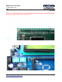
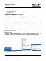
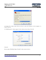
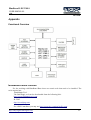
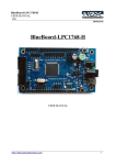
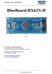
BlueBoard LPC1768-S
USER MANUAL
v1.0
1/07/2010
BlueBoard LPC1768-S
USER MANUAL
http://shop.ngxtechnologies.com
1
BlueBoard LPC1768-S
USER MANUAL
v1.0
1/07/2010
Table of Contents
Introduction..........................................................................................................................................3
Features.................................................................................................................................................3
Hardware.....................................................................................................................................3
Software......................................................................................................................................4
Getting Started......................................................................................................................................4
Requirement ....................................................................................................................................4
Hardware.....................................................................................................................................4
Software......................................................................................................................................4
Setup.....................................................................................................................................................4
Hardware.....................................................................................................................................4
Software......................................................................................................................................6
Validating BlueBoard LPC1768-S.......................................................................................................6
Programming BlueBoard LPC1768-S................................................................................................12
Programming BlueBoard Through ISP..........................................................................................12
1. Auto Mode:...........................................................................................................................12
2. Manual Mode:.......................................................................................................................12
Programming and Debugging with JTAG.....................................................................................13
Appendix............................................................................................................................................14
Functional Overview......................................................................................................................14
BlueBoard Base Utilities....................................................................................................................14
Schematics..........................................................................................................................................15
Sample Code.......................................................................................................................................15
Known Issues......................................................................................................................................16
Information.........................................................................................................................................17
Revision History......................................................................................................................17
Legal.........................................................................................................................................17
Disclaimers ..............................................................................................................................17
Trademarks ..............................................................................................................................17
http://shop.ngxtechnologies.com
2
BlueBoard LPC1768-S
USER MANUAL
v1.0
1/07/2010
Introduction
The BlueBoard LPC1768-S is an add on board to the BlueBoardBase. The S signifies it as a
stamp module. The BlueBoard Base can be used wih different microcontrollers to interface with
various pheripheral connectors on it to facilitate the interfacing.
Features
The BlueBoard LPC1768-S is mounted on a board with connecting pins.
Hardware
•
•
•
•
•
Dimensions of 47 X 47 mm2
Two layer PCB (FR-4 material)
32 Khz crystal for RTC
12 Mhz for Controller
Test LED
Software
Preloaded firmware to test the peripherals on the BlueBoard Base.
Getting Started
Before starting you would need the following.
Requirement
The requirement is put in two sections.
Hardware
Refer to BlueBoard Base documentation here.
Software
Refer to BlueBoard Base documentation.
Setup
Hardware
Mount the stamp board on to BlueBoard Base. Mounting has to be made with proper
orientation.
Note: Failure to mount the stamp in proper orientation on to the BlueBoard Base could render
your stamp board and / the Base unusable and cause permannt damage. Kindly mount it as shown
in the manual.
http://shop.ngxtechnologies.com
3
BlueBoard LPC1768-S
USER MANUAL
v1.0
1/07/2010
The arrow (<) marked pin (P1) on stamp should go into the first pin on J1 on the base board.
Refer to the images marked with a yellow circle.
http://shop.ngxtechnologies.com
4
BlueBoard LPC1768-S
USER MANUAL
v1.0
1/07/2010
Software
•
•
PC with WINDOWS XP
Hyperterminal
Validating BlueBoard LPC1768-S
Once you have all these accessories connected to the BlueBoard Base you can run a simple
test to verify the proper working of all the peripherals. It is highly recommended that you test all the
peripherals as soon you receive the BlueBoard. The BlueBoard is shipped with the preloaded
firmware which can test all the peripherals.
LEDs and SPI0
Test setup: Connect jumpers to all pins of J9 to enable the LED's.
After the Blueboard is turned ON or reset; the LEDs will turn ON and OFF a few times.
Please note that all the LEDs should glow; this confirms the working of LEDs. Now, since the
LEDs are connected through a serial to parallel converter this test also confirms the working of
SPI0 of the LPC.
Test LED on Stamp
Test setup:
The LED is on the stamp board. No seperate setup required. The LED will blink a
few times on reset or power on.
UART0 & UART3
Test setup: Connect jumpers to all pins of J6. Open the hyper terminal as shown in the
image below. To test the UART you can use either a full modem or half modem cable.
Click on hyper terminal a “Connection Description” window opens. Enter a name under the name
tab e.g. BlueBoard and click OK.
http://shop.ngxtechnologies.com
5
BlueBoard LPC1768-S
USER MANUAL
v1.0
1/07/2010
A “Connect To” window opens where you have to select the COM port. In this example it is
COM1.Click OK.
A “COM1Properties” window appears. Set the values as shown below.Click OK.
Click OK.
Next an empty “BlueBoard-Hyper Terminal” window opens as shown.
http://shop.ngxtechnologies.com
6
BlueBoard LPC1768-S
USER MANUAL
v1.0
1/07/2010
Now make sure that the BlueBoard is powered and the serial port is connected to the
respective port to be tested (UART0 or UART3). By pressing any key from keyboard the same will
be echoed back on the terminal.
For UART0:
Loop back test can be done for UART 0.
UART0 can also be used for serial programming. If the selected bootloader mode is Manual
then Half modem cable should be used, else if it is in Auto mode use full modem cable. Note that
after programming in auto mode the serial cable should be disconnected.
For UART3:
Loop back test can be done for UART 3 also.
http://shop.ngxtechnologies.com
7
BlueBoard LPC1768-S
USER MANUAL
v1.0
1/07/2010
USB
The USB connector can also be used to powerup the board. In Windows XP it will be
detected as a Human Interface Device.
Test setup: Connect the USB cable to USB connector. The power LED (D14) and USB connect
LED (D10) turn ON.
VGA connector – code presently not available
Test setup: -- NA -JTAG connector
Test setup: To enable debugging on the board connect jumper to J11 and connect the JTAG to
debug port. We have successfully tested the BlueBoard with JTAG interface using a Wiggler Clone
JTAG. To test this feature you need to have the necessary software support on your PC. Also the
NGX USB JTAG can used with. Refer to the documentation here.
User Interface Switch
Test setup: The Switch SW1 is connected to one of the external interrupt lines of LPC. To test
this interface simply press the switch and you should hear the beep sound on the buzzer. This
confirms that both the interrupt line and the buzzer module are working fine. Please ensure that you
have connected the buzzer jumper appropriately.
Buzzer
Test setup: Connect jumper to J23, when the board is turned on or RESET you will hear a few
beeps. This is how the user can confirm the status of the Buzzer.
SD/MMC connector
Note: Do this test in the end as a new firmware has to be flashed and the previous test firmware will
be overwritten.
Test setup: To test the SD card a new firmware has to be loaded. This can be done using the Hhttp://shop.ngxtechnologies.com
8
BlueBoard LPC1768-S
USER MANUAL
v1.0
1/07/2010
JTAG. The firmware file can be found here. Insert a SD card in the SD card holder (J24). The board
was tested with a Kingston’s 1GB SD card. Reset the board. A text file 'sdtest.txt' will be written on
the SD card. Verify this using a card reader on PC / Laptop.
Note: The SD/MMC card being tested should be formatted with FAT file system (Not FAT32 or
NTFS format).
Audio jack
Test setup: Connect a headset to the audio jack connector. You should hear some random sound.
The sound is heard only for few seconds after power ON or RESET.
PS/2 keyboard – code presently not available
Test setup:
-- NA --
LCD display
Test setup: To enable the LCD connect jumpers to all pins of J18. A default message “NGX
TECHNOLOGIES” will be displayed and later status of SD/MMC and I2C is displayed. The back
light of LCD can be controlled by connecting jumper to appropriate pins of J19. The contrast of
LCD can be varied using the POT.
RTC: A 2 - pin connector J27 is provided for RTC.Connect an external battery to use the to this
connector to work with RTC.
ADC: The ADC is connected to a potentiometer. To test the ADC turn the potentiometer, as the
position varies the output number of LEDs that are turned ON varies.
Programming BlueBoard LPC1768-S
BlueBoard LPC1768-S can be programmed through wiggler clone JTAG or through serial
port using ‘Flash Magic’. ‘Flash Magic’ is a freeware windows utility used download the hex file
format onto the BlueBoard. Flash Magic can be downloaded from here
http://www.flashmagictool.com/. If your PC does not have a serial port; use a USB to serial
converter to download the hex file using the Flash Magic utility. For programming with JTAG your
system should have a parallel port or you can use the USB to JTAG from NGX Technologies and
the supporting IDE which can communicate to the processor core over JTAG interface. We have
successfully tested BlueBoard with wiggler clone JTAG and USB JTAG with CrossWorks IDE. A
LINUX utility to download the hex file can be found here http://www.pjrc.com/arm/lpc2k_pgm/.
Programming BlueBoard Through ISP
The BlueBoard Base can be programmed through ISP in two modes:
1. Auto Mode
2. Manual Mode
http://shop.ngxtechnologies.com
9
BlueBoard LPC1768-S
USER MANUAL
v1.0
1/07/2010
1. Auto Mode:
To program in Auto mode you need a full serial cable. Set the jumper to pins 2 & 3 of J26
and connect the full serial cable to UART0 (J5). When BlueBoard is powered ON black boxes will
be displayed on LCD. Open Flash Magic tool, select the appropriate COM port, set the Baud rate to
less than or equal to 38400 bps, select device as LPC1768, interface as 'None (ISP)' and oscillator
frequency as 12MHz. Specify the path of your HEX file and click START. The status is shown at
the bottom on the Flash Magic window.
In the 'Step 4 - Options' check 'Verify after programming' and 'Fill unused flash' options.
Checking the 'Set Code Read Prot' option will not allow you will program with JTAG. So keep it
unchecked unless required.
Note:
1. In Auto mode under the 'Options' tab select 'Advanced options'. In this under 'Hardware
Config' tab make sure the options 'Use DTR and RTS to control RTS and P0.14' and 'Keep
RTS asserted while COM port open' are checked. The values of T1 and T2 are set to 100ms
and 200ms by default.
2. After programming the board in Auto mode you should disconnect the serial cable from J5.
This is a known issue.
2. Manual Mode:
To program in Manual mode you need a half serial cable (which just has TX, RX and GND
wire connected). Set the jumper to pins 1 & 2 of J26 and connect the half serial cable to UART0
(J5) and power the board.
To make the board enter programming mode
• Hold down SW2 (ISP) and SW3 (RESET), then release SW3 first and finally SW2
• The controller enters the bootloader mode if during reset the SW2 pin is low
Programming and Debugging with JTAG
The Blueboard can be programmed and debugged either using parallel port or USB JTAG.
•
NGX Parallel Port JTAG using H-JTAG (refer here)
•
NGX USB JTAG (refer here)
http://shop.ngxtechnologies.com
10
BlueBoard LPC1768-S
USER MANUAL
v1.0
1/07/2010
Appendix
Functional Overview
BlueBoard Base Utilities
For the working with BlueBoard Base there are certain tools that need to be installed. The
tools required are:
Flash Magic Tool.
The flash magic tool can be downloaded from the following link:
http://www.flashmagictool.com/
H-JTAG
http://www.hjtag.com/
For LINUX machines you may use http://www.pjrc.com/arm/lpc2k_pgm/
http://shop.ngxtechnologies.com
11
BlueBoard LPC1768-S
USER MANUAL
v1.0
1/07/2010
Tool chain:
To be able to generate the hex or the binary file the user needs to install the tool chain for
ARM based microcontrollers. Any toolchain can be used as long as it is able to generate the
necessary files for downloading onto the BlueBoard. Here are few toolchain suggestions:
GNUARM Toolchain: http://winarm.scienceprog.com/winarm-tools/prepare-gnuarm-compilertoolchain-for-windows.html
Crossworks IDE: http://www.rowley.co.uk/arm/
IAR Systems: http://www.iar.com
•
•
•
•
•
•
•
•
•
•
•
•
•
•
Analog to Digital Converter
UART
I2C
E2PROM Driver - Reading and writing to an i2c-e2prom
SPI - Using SPI in polled master mode to drive 8 x LEDs
FIQ Handler
VGA – code presently not available
Timer
Soft Timer - Demonstrates multiple timers with callbacks
Watchdog
SD/MMC access
PS2 - Code to demonstrate PS2 keyboard – code presently not available
Audio - Code to demonstrate wav playback
Buzzer- Code to demonstrate buzzer on external interrupt
Schematics
Refer to the documentation here.
Sample Code
Download the zipped file here.
http://shop.ngxtechnologies.com
12
BlueBoard LPC1768-S
USER MANUAL
v1.0
1/07/2010
Known Issues
While using the Auto-program mode for ISP; after programming the BlueBoard Base, user
needs to unplug the full modem serial cable for the program to execute.
http://shop.ngxtechnologies.com
13
BlueBoard LPC1768-S
USER MANUAL
v1.0
1/07/2010
Information
Revision History
version: v1.0 author: Milind Kakati
Legal
NGX Technologies Pvt. Ltd. provides the enclosed product(s) under the following conditions:
This evaluation board/kit is intended for use for ENGINEERING DEVELOPMENT, DEMONSTRATION, EDUCATION OR
EVALUATION PURPOSES ONLY and is not considered by NGX Technologies Pvt. Ltd to be a finished end-product fit for general
consumer use. Persons handling the product(s) must have electronics training and observe good engineering practice standards. As
such, the goods being provided are not intended to be complete in terms of required design-, marketing-, and/or manufacturingrelated protective considerations, including product safety and environmental measures typically found in end products that
incorporate such semiconductor components or circuit boards. This evaluation board/kit does not fall within the scope of the
European Union directives regarding electromagnetic compatibility, restricted substances (RoHS), recycling (WEEE), FCC, CE or
UL, and therefore may not meet the technical requirements of these directives or other related directives.
The user assumes all responsibility and liability for proper and safe handling of the goods. Further, the user indemnifies NGX
Technologies from all claims arising from the handling or use of the goods. Due to the open construction of the product, it is the
user’s responsibility to take any and all appropriate precautions with regard to electrostatic discharge.
EXCEPT TO THE EXTENT OF THE INDEMNITY SET FORTH ABOVE, NEITHER PARTY SHALL BE LIABLE TO THE
OTHER FOR ANY INDIRECT, SPECIAL, INCIDENTAL, OR CONSEQUENTIAL DAMAGES.
NGX Technologies currently deals with a variety of customers for products, and therefore our arrangement with the user is not
exclusive. NGX Technologies assumes no liability for applications assistance, customer product design, software performance, or
infringement of patents or services described herein.
Please read the User’s Guide and, specifically, the Warnings and Restrictions notice in the User’s Guide prior to handling the product.
This notice contains important safety information about temperatures and voltages.
No license is granted under any patent right or other intellectual property right of NGX Technologies covering or relating to any
machine, process, or combination in which such NGX Technologies products or services might be or are used.
Disclaimers
Information in this document is believed to be reliable and accurate. However, NGX Technologies does not give any representations
or warranties, expressed or implied, as to the completeness or accuracy of such information and shall have no liability for the
consequences of use of such information.
NGX Technologies reserves the right to make changes to information published in this document, at any time and without notice,
including without limitation specifications and product descriptions. This document replaces and supercedes all information supplied
prior to the publication hereof.
Trademarks
All referenced trademarks, product names, brands and service names are the property of their respective owners.
http://shop.ngxtechnologies.com
14