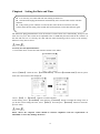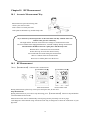
1
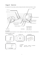
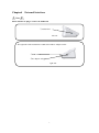
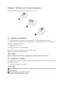
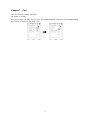
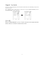
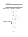
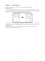
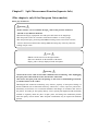
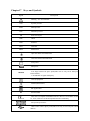
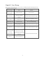
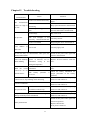
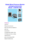
User Manual Electronic Sphygmomanometer Model CONTEC08A ■ To assure the correct use of the product safety measures, please carefully read user manual before using. ■ After reading, please validly keeping to refer and consult at any moment. Contents Chapter1 Safety Precautions ...................................................................................................................... 1 Chapter2 Main Unit.................................................................................................................................... 4 Chapter3 Button Functions......................................................................................................................... 6 Chapter4 External Interfaces ...................................................................................................................... 7 Chapter5 Dry Battery/AC Adapter Installation .......................................................................................... 8 5.1 Dry Battery Installation ................................................................................................................ 8 5.2 Using the AC Adapter .................................................................................................................. 8 Chapter6 Setting the Date and Time......................................................................................................... 10 Chapter7 Unit ........................................................................................................................................... 11 Chapter8 User Switch............................................................................................................................... 12 Chapter9 Applying the Arm Cuff ............................................................................................................. 13 Chapter10 BP Measurement ..................................................................................................................... 14 10.1 Accurate Measurement Way..................................................................................................... 14 10.2 BP Measurement ...................................................................................................................... 14 Chapter11 Memory Function ................................................................................................................... 16 11.1 Review the Memory Value ....................................................................................................... 16 11.2 Delete Memory Values ............................................................................................................. 17 Chapter12 Alarm Function ....................................................................................................................... 18 Chapter13 SpO2 Measurement Function(Separate Sale) .......................................................................... 19 Chapter14 Monitoring Procedure ............................................................................................................. 20 Chapter15 Maintenance and Cleaning ..................................................................................................... 21 Chapter16 Installation of the Software..................................................................................................... 22 16.1 Demand of Editor ..................................................................................................................... 22 16.2 Installation of Software ............................................................................................................ 22 Chapter17 Keys and Symbols .................................................................................................................. 23 Chapter18 Error Message ......................................................................................................................... 24 Chapter19 Troubleshooting ...................................................................................................................... 25 Chapter20 Clean and Maintenance........................................................................................................... 26 Chapter21 NIBP Specification ................................................................................................................. 28 Chapter22 SpO2 Specification .................................................................................................................. 30 Appendix ..................................................................................................................................................... 31 I Chapter1 Safety Precautions Before use, carefully read "Safety Precautions" for a correct use. To prevent users suffered hurt or damnification due to improper use, see "Safety Precautions", and use this product properly. For safety reasons, be sure to comply with safety precautions. Note If not to use correctly, it exists that a potentially hazardous situation which may result in injury to the user or patient or damage to the equipment or other property. Note Self-diagnosis and treatment using measured results may be dangerous. Follow the instructions of your physician. Contact your physician for specific information about your blood pressure. Please hand measurement results to the doctor who know your health to accept diagnosis. For severe blood circulation disorder or arrhythmia patients, please use the device under the guidance of a doctor. Otherwise it may lead to acute hemorrhage, or measurement error as a result of squeezed arm. This device is intended for using in measuring blood pressure and pulse rate. Do not use for any other purpose. Otherwise it may cause accident or holdback. Please use special cuff. Otherwise it is possible that measurement result is incorrect. Do not disassemble or attempt to repair the unit or components without permission. Otherwise it can not measure correctly 1 Operation for AC Adapter (Separate Sale) Note Please use sold separately dedicated AC adapter. Otherwise it may cause trouble. Sold separately dedicated AC adapter be sure to use a separate socket. Otherwise it may cause electric shock or injury. When there is breakage of sold separately dedicated AC adapter plug or wire , please immediately pulled the plug from the socket. Otherwise it may cause electric shock or injury. Do not plug or unplug the adapter power cord with wet hands. Otherwise it may cause electric shock or injury. Operation for battery Note Please use 4 "AA" size manganese or alkaline batteries, do not use batteries of other types. Otherwise it may cause fire. New and old batteries, different kinds batteries can not be confusion. Otherwise it may cause battery leakage, heat, rupture, and damage to Electronic Sphygmomanometer. + and - polarities of the batteries must match the polarities of the battery compartment as indicated. When the batteries power exhausts, replace with four new batteries at the same time. Please take out the batteries when you do not use the device for a long time. Otherwise it may cause battery leakage, heat, rupture, and damage to Electronic Sphygmomanometer. If battery fluid should get in your eyes, immediately rinse with plenty of clean water. Contact a physician immediately. Otherwise it will cause blindness or other hazards. If electrolyte of the batteries immodestly glues on the skin or the clothes, immediately rinse with plenty of clean water. Otherwise it may hurt the skin. Advice Do not subject the device to strong shocks, such as dropping the unit on the floor. Do not inflate before the cuff wrapps around the arm Do not inflect the cuff and the air tube forcibly This device is intended for using in measuring blood pressure and pulse rate in the adult, pediatric and neonatal population. 2 Warning Please use the device on the adult object who can read the user manual and the error message shown on the screen. Read the user manual before use the device in order to take actions according to the manual when something wrong with the device. For pediatric and neonatal population, measurement should be only performed by qualified personnel. And please make sure to select the right user mode and cuff before use . 3 Chapter2 Main Unit The production is in the package. Open the package and confirm whether the production is whole. Display Cuff Plug jack Cuff Air Plug jack UP/DOWN Button AC Adapter Jack MENU Button USB Plug Jack USER SWITCH Button ON/OFF Button START/STOP Button Adult Cuff Dry Battery Accessories: (Specification: limb circumference 22-32cm (middle part of upper arm), please choose suited cuff when measuring pediatric or other). USB Data Line Software CD User Manual Separate Sale: AC Adapter InputAC 100-240V 50-60Hz AC 500mA Output DC 6.0V±0.2V 1.0A 4 (This part is only fit for European Union market) SpO2 Probe Y10UCH150 SpO2 Measurement Range 35%~100 % Measurement Accuracy 70%~100% ±2% Pulse Measurement Range 30~250bpm Error the large of ±2bpm and ±2% 5 Chapter3 Button Functions All the operations to the Electronic Sphygmomanometer are through the buttons. The names of the buttons are above them. They are: 【ON/OFF】 Hold the button to start or close the device. 【START/STOP】 Press to inflate the cuff and start a blood pressure measurement. When measuring, press to cancel the measurement and deflate the cuff. The three buttons correspond with the hint in the LCD screen downside, pressing any button will carry on corresponding function, eg:【MENU】 【ENTER】 【LIST】 etc. Up and down buttons respectively carry on the functions of moving the cursor up and down, changing the parameters and switching the status. 6 Chapter4 External Interfaces Note Please hold the air plug to remove the NIBP cuff. ①Cuff Socket left side The right side of the instrument is USB socket and AC adapter socket. ①USB socket ②AC adapter socket right side 7 Chapter5 Dry Battery/AC Adapter Installation The production can use dry battery or AC adapter as power source. 5.1 Dry Battery Installation ① Press the▲indicator on the battery cover and slide the cover off in the direction of the arrow. ② Install 4 "AA" size dry batteries so the +(positive) and 一(negative) polarities match the polarities of the battery compartment as indicated. ③ Replace the battery cover. Icon “ ”: the batteries power will exhaust. Replace with four new batteries (the same sort) at the same time. Turn the unit off before replacing the batteries. Note Dispose of the batteries according to applicable local regulations about environmental. 5.2 Using the AC Adapter ① Connect device and the AC Adapter. Insert the AC Adapter Plug into the AC Adapter Jack on the right side of the device. ② Plug the AC Adapter into a AC outlet. Note ①Hold and pull the Housing to remove the AC Adapter from the electrical outlet. Do not remove by pulling on the cord. ②Remove the AC Adapter plug from the unit. Please be sure to use dedicated AC adapter. 8 Note You'd better take off batteries when use the AC adapter as power source. If there is any damage to the AC adapter, you should use batteries to run the device. When adapter and batteries are both used at the same time, the battery power will not be consumed. Switch adapter and battery as power supply when the device is off, otherwise, the device may shutdown due to power failure. 9 Chapter6 Setting the Date and Time It is necessary to set date and time after turning on the device. The Electronic Sphygmomanometer automatically stores measurement results with date and time. If dry battery power exhausts or removed, then, after the device turned on, the date resumes from the last setting value and the time from 00:00:00, set the date and time again. The Electronic Sphygmomanometer stores the measure results of three users automatically, and up to 100 items for every user. The results can be uploaded to PC via USB and processed with the PC software. If the date and time are set correctly, the date and time when measuring will be correct in the memory, otherwise it may not be correct. Note Correctly use data upload function: 1. Turn on the device to enter the main interface shown as the follow: 2.Press 【MENU】 button to enter 【SYSTEM MENU】 and select【SYSTEM TIME】 item in system menu. The current time will be displayed: 3.Press 【UP】 or 【DOWN】 buttons to set date and time. 4.After setting, select 【CONFIRM】 item and press 【ENTER】 button to confirm the setting value. If you do not want to change the time, select 【EXIT】 item and press 【ENTER】 button to return the previous menu. Note Please choose the computer which should be ensured compliance with the requirements of IEC60950, or else it may damage the device. 10 Chapter7 Unit There are two units: "mmHg" and "kPa". The default is: "mmHg". To switch "mmHg" and "kPa" units, enter the 【SYSTEM SETUP】 submenu in 【SYSTEM MENU】, and complete switching in 【UNIT】 item. 11 Chapter8 User Switch The Electronic Sphygmomanometer stores the measure results of three users automatically, and up to 100 items for every user. Press 【USER】 button in main interface to switch users. Or press 【USER PURVIEW】 item in 【SYSTEM SETUP】 menu to switch users. Note When the 【USER PURVIEW】 is set to be 【ALL】, current user can be switched under main interface; when set to a certain user, it will not be able to switch. 12 Chapter9 Applying the Arm Cuff The measurement can be carried out by applying the cuff on left or right arm. Remove tight-fitting clothing from your upper arms. Carry out the operation in a room with comfortable temperature. When measuring, take the thick clothes off instead of rolling up the sleeves. In order to measure accurately, pay attention to applying the cuff properly (left arm). ① Make sure the air plug is securely inserted in the main unit. ② Stretch cuff into a barrel for the arm can conformable enter into the barrel. ③ Arm penetrate throught the cuff, the air tube of the cuff will pass the top of your palm. ④ Apply the cuff to your upper arm. The color marker is on the inside center of your arm and make the air tube aligned with your middle forger. ⑤ The bottom of the cuff should be approximately 2cm~3cm above your elbow. ⑥ Be fixed with cloths, and wrapped tight cuff, the arm and the cuff should not have gaps. 13 Chapter10 BP Measurement 10.1 Accurate Measurement Way Measurement in quiet and relaxing state. 1.Place your arm on a table. 2.The cuff is level with your heart. 3.The palm of the hand is up, and the body relax Try to measure your blood pressure at the same time each day with the same arm and the same pose for consistency. The high and low location of cuff will cause changes in measurement results. Do not touch Electronic Sphygmomanometer, cuff and windpipe during measurement. Measurements should be taken in a quiet place and the body relax. Remain still 4~5 minutes before measurement. Relax the body, do not let the muscle activity. Do not talk and movement during the measurement. Wait 4~5 minutes between measurements. Do not use a cellular phone near the device. 10.2 BP Measurement ①Press 【START/STOP】 button to take a measurement. Start measurement measurement result During measurement, please keep correct pose and quiet state, do not move. Stop Measurement During measurement, if you wish to stop measuring, press 【START/STOP】 button to stop and deflate. ②Confirm Measurement Value Measurement value can be automatically stored.([using memory function] refer to 10 page) *Self-diagnosis and treatment using measured results may be dangerous. Follow the instructions of your physician. 14 Note Wait 4-5 minutes between measurements. When repeated measurements, because, the arm appears congestion, it may not get correct blood pressure measurement. After the blood flow, take a measurement once again. When some factors affect the measurement results in measurement process, error messages hints will appear on the screen, you can obviate the malfunction and restart a measurement. ③In no physiological alarm state, press any button to carry on the corresponding button function; in audio alarm state, press any button (except 【ON/OFF】 button) to clear up the audio alarm. ④Take off the cuff, hold 【ON/OFF】 button to turn the device off. *The device will automatically turn off after two minutes in which there is no operation to the device, even if you forget to turn the power off. 15 Chapter11 Memory Function The devicer is designed to store and display the blood pressure, pulse rate values and the date and time when measured, which are up to 100 items. If there have been 100 items stored, when the 101 measurement have been taken, the earliest results are deleted. 11.1 Review the Memory Value 1.In the main interface (interface when boot-strap), press 【MEMORY】 button to review the most recent measurement values in large-print with the serial number from 1 to 100. 2.Press 【UP】/【DOWN】 button to circularly switch the former measurement values. *The right figure shows that there is no Measurement result. 3.Press 【LIST】 button to switch to data table interface. 4.Press 【TREND】 button to display trend interface. 5.Finish displaying the measurement values 16 Press 【EXIT】 to return the main interface or hold 【ON/OFF】 button to turn the power off. *The device will automatically turn off after two minutes in which there is no operation to the device, even if you forget to turn the power off. 11.2 Delete Memory Values Users can delete all values stored in the memory of each user separately instead of deleting a special item. 1.Press 【MENU】 button to enter 【SYSTEM MENU】, select 【DELETE DATA】 item and enter its interface, in which select the user whose data will be deleted. All measurement results of selected user will be deleted after confirm 2.Finish Operation Select 【CONFIRM】 or 【EXIT】 to return the previous menu, or hold 【ON/OFF】 button to turn the power off. *The device will automatically turn off after two minutes in which there is no operation to the device, even if you forget to turn the power off. 17 Chapter12 Alarm Function Alarms are classified into two categories: technical alarm and physiological alarm. Physiological Alarm User can press 【MENU】 button to enter system menu, select 【ALARM SETUP】 item to enter its interface, and then set alarm on-off and the high and low alarm limits, when blood pressure is higher than the high limit or lower than the low limit, the physiological alarm will occur. Press any button to cancel the alarm in physiological alarm state and this method brings no affection to the next alarm. To close alarm in 【ALARM SETUP】 will disable the alarm function until switch alarm on. Technical Alarm When power is about to exhaust and alarm is on , then the alarm will occur. This alarm can not be cancelled unless being closed or the power replaced. 18 Chapter13 SpO2 Measurement Function(Separate Sale) (This chapter is only fit for European Union market) Please pay attention to: Warning ◎Pulse oximeter can overestimate the SpO2 value in the presence of Hb-CO, Met-Hb or dye dilution chemicals. ◎ES (Electrosurgery) equipment wire and SpO2 cable must not be tangled up. ◎Do not put the sensor on extremities with arterial catheter or venous syringe. ◎Do not perform SpO2 measuring and NIBP measuring on the same arm at one time, because obstruction of blood flow during NIBP measuring may adversely affect the reading of SpO2 value. Note ◎Make sure the nail covers the light window. ◎the wire should be on the backside of the hand. ◎SpO2 value is always displayed in the fixed place. Warning ◎Check if the sensor cable is in normal condition before monitoring. After unplugging the SpO2 probe cable from the socket, the interface will return. ◎Do not use the SpO2 probe once the package or the sensor is found damaged. Instead, you shall return it to the vendor. ◎Prolonged and continuous monitoring may increase jeopardy of unexpected change of dermal condition such as abnormal sensitivity, erubescence, vesicle, repressive putrescence, Particularly in newborns or in a Perfusion disorders and changes or immature skin form of the patient. According to skin quality change, correct optical path alignment and attachment methods to regularly check the place of SpO2 probe, and change the attachment position when the quality of skin decline. More frequent examinations may be required for different patients. 19 Chapter14 Monitoring Procedure (This chapter is only fit for European Union market) 1.Attach the sensor to the appropriate site of the patient finger as following figure. Place SpO2 2.Plug the connector of the SpO2 probe cable into the USB socket in the lower right of the device. The main interface will switch to SpO2 interface. The update period of data is less than 5 seconds, which is changeable according to different individual pulse rate. This operation brings no affection to other functions. Warning Uncomfortable or painful feeling may appear if using the device ceaselessly, especially, for the microcirculation barrier patients. It is recommended that the sensor should not be applied to the same finger for over 2 hours. Measurement Limitations During operation, the accuracy of oximeter readings can be affected by: High-frequency electrical noise, including noise created by the host system, or noise from external sources, such as electrosurgical apparatus connected to the system. Intravascular dye injections. Excessive patient movement. External light radiation. Improper sensor installation or incorrect contact position of the patient. SpO2 probe temperature (optimal temperature between 28°C and 40°C). Placement of the SpO2 probe on an extremity that has a blood pressure cuff, arterial catheter, or intravascular line. Significant concentrations of dysfunctional hemoglobin, such as carboxyhemoglobin and methemoglobin. SpO2 too low. Bad circular injection of the part being measured. It is required to use SpO2 probe which is provided by our company, contact with our sale department when changes SpO2 probe. 20 Chapter15 Maintenance and Cleaning (This chapter is only fit for European Union market) Warning Take cuff and the power source off before cleaning the unit or the SpO2 probe. Caution Do not subject the sensor to autoclaving. Do not immerse the SpO2 probe into any liquid. Do not use any SpO2 probe or cable that may be damaged or deteriorated. Cleaning: Use a cotton ball or a soft mull moistened with hospital-grade ethanol to wipe the surface of the SpO2 probe, and then dry it with a cloth. This cleaning method can also be applied to the luminotron and receiving unit. The cable can be cleaned with 3% hydrogen dioxide, 70% isopropanol, or other active reagent. However, connector of the SpO2 probe shall not be subjected to such solution. 21 Chapter16 Installation of the Software 16.1 Demand of Editor Pentium IV 1.8G or more Operation System:Windows XP EMS memory: 256M or more Hard Disk: 40G or more Display: 17 inch or more CD-ROM USB: 2 or more Resolution of printer: 600 DPI 16.2 Installation of Software 1.Place the CD-ROM in the CD-ROM compartment located on your computer. 2.If Auto Play for CDs is enabled, place CD in reader and follow instructions when they appear in the screen; otherwise follow install instructions below: 1.Open Windows Explorer. 2.Click on the root CD-ROM directory. 3.Double click file setup software. 4.Follow the instructions in the screen. Refer to "Software Help"for details about the operation method of the PC software. 22 Chapter17 Keys and Symbols Signal Description Warning – See User Manual SYS Systolic pressure MAP MAP pressure DIA Diastolic pressure PR Pulse rate (bpm) ADU Adult PED Pediatric NEO Neonatal INFO Information Open the alarm sound indication Close the alarm sound indication Low-power Full-power 1.no NIBP data to review 2.no finger inserted to SpO2 probe(This item is only fit for European Union market) 3.An indicator of signal inadequacy ClassⅡequipment WEEE (2002/96/EC) BF Applied Part SN Serial number This item is compliant with Medical Device Directive 93/42/EEC of June 14, 1993, a directive of the European Economic Community. European Representative USB socket connect SpO2 probe(This item only fit for European Union market) 23 Chapter18 Error Message Error message will be displayed in the screen if there is something wrong when measuring. The causes and solutions are shown as follows: Error Message Causes Solutions Function abnormal Please contact us Self-test failure System failure Cuff is not connected Loose cuff Correctly connect cuff (refer to 8 page) correctly. Make sure the cuff plug is securely Air leakage Cuff plug fall off inserted in the windpipe (refer to 8 page) Air pressure error Air pressure error Refer to the troubleshooting The pulse signal is too weak Weak signal Correctly connect cuff (refer to 8 page) or the cuff is loose. overpressure Cuff is blocked or squeezed Correctly connect cuff (refer to 8 page) The signal extent is too big Excessive movement owing to the arm or body Over range moving or other reasons when Saturated signal Keep arm, body still, measure again measuring Time out It takes too much time 24 Chapter19 Troubleshooting Abnormal Phenomenons BP measurement values too high or too low. No pressure Cuff deflates short time in Causes Solutions Cuff is not connected correctly. Correctly connect cuff (refer to 8 page) Talk or move arms when measuring Keep quiet and restart a measurement The turnup clothing presses the arm Take off the clothing which presses the arm, and restart a measurement Cuff leakage Buy a new cuff The cuff windpipe is not correctly connected with cuff Correctly connect Cuff is not inflated Stop using the device and contact us Loose cuff Correctly apply cuff It can not carry on measurement when press the measurement button Switch on the power once again and restart a measurement No use for a long time, the power of batteries can be exhausted owing to the changed temperature Replace all four batteries with new ones. Power of batteries can be exhausted Replace all four batteries with new ones. The battery reversed Check the battery installation for proper placement of the battery polarities. Power off suddenly when inflating Hold the on/off button but can not start the device polarities is Cuff inflation start before press the measurement button or never stop inflating when measuring Pull out the cuff to deflate. Stop using the device and contact us. Cuff never deflation Pull out the cuff to deflate. Stop using the device and contact us. Air pressure error No deflation or deflation error or inflation without stop Pull out the cuff to deflate. Stop using the device and contact us. Others Keep arm, body still, measure again. No press value displayed or the value unchanged or change erratically when cuff inflated Pull out the cuff to deflate. Stop using the device and contact us. Other phenomenon Switch on the power once again and restart an operation. Replace the batteries. If no, please contact us. 25 Chapter20 Clean and Maintenance *Please follow the instructions in the user manual. If you do not comply, our company will not assume responsibilities of the quality. Frequently clean the Electronic Sphygmomanometer. If there is something dirty on the device, clean it with a soft dry cloth. If the unit is particularly dirty, you can clean it with a soft cloth dampened with water or neutral detergent after the cloth can be full twisted. Warning Do not submerge the device in water. Advice Do not use any naphtha, thinner or gas to clean. Do not attempt to clean or wash the cuff. Keeping Advice Do not place the machine in the following areas: Easy to splash water areas. Direct sunlight, extreme hot, humidity, dust, causticity gas areas. Lean or the area which can cause vibration, impact. 26 Chemicals or corrosive gas storage areas. Remove the batteries if the unit will not be used for long time. Warning It is recommended that you check if there is any damage on the Sphygmomanometer or the accessories regularly, if you find any damage, stop using it, and contact our Customer Service immediately. In addition, the overall check of the Sphygmomanometer, including the NIBP calibration and safety check such as the leakage current, should be only performed by qualified personnel once every 12 months. Warning The disposal of scrap instrument and its accessories and packing (including batteries, plastic bags, foams and paper boxes) should follow the local laws and regulations. EMC declaration: When this device is installed or putted into service, EMC should be paid more attention, as the portable and mobile RF communications equipment with higher EM interference can affect this device. The internal components and cables should not be changed,as this may decreased IMMUNITY of the device. The Electronic Sphygmomanometer should not be used adjacent to or stacked with other equipment. Classification: EMC: Group I Class B. According to the MDD 93/42, the classification of this medical device: Ⅱa. The type of protection against electroshock: ClassⅡequipment. The degree of protection against electroshock: type BF applied part . The degree of protection against ingress of water: IPX0. According to the mode of operation: Continuous. According to the degree of safely of application in the presence of a flammable anesthetic mixture with air or with oxygen or nitrous oxide: Equipment not suitable for use in the presence of a flammable anesthetic mixture with air or with oxygen or nitrous oxide. 27 Chapter21 NIBP Specification Name Electronic Sphygmomanometer Display 2.8'' color LCD Display NIBP Specifications Measurement Method Oscillometric method Working modes Automatic Measurement Range Pressure adult 0~290mmHg(0~38.6kPa) pediatric 0~235mmHg(0~31.3kPa) neonatal 0~140mmHg(0~18.6kPa) Pulse: 40~240/min Inflation Alarm Range Overpressure protect adult 160mmHg pediatric 120mmHg neonatal 70mmHg adult mode SYS ALM: 40~270 mmHg DIA ALM: 10~215 mmHg pediatric mode SYS ALM: 40~200 mmHg DIA ALM: 10~150 mmHg neonatal mode SYS ALM: 40~135 mmHg DIA ALM: 10~100 mmHg adult mode 295±5mmHg pediatric mode 240±5mmHg neonatal mode 145±5mmHg Resolution Pressure 1mmHg Measurement Accuracy Cuff Pressure Accuracy ±3mmHg Error The BP Value of the device is equivalence with the measurement value of Stethoscopy. The error meets all the conditions in the ANSI/AAMI SP-10:2002+A1:2003 +A2:2006. Operating Temperature/ Humidity +5ºC~40 ºC . 15%RH~80%RH Transport and Storage Temperature/Humidity -20ºC~+55ºC . ≤95%RH Atmospheric pressure 80kPa~105kPa Battery 4 "AA" alkaline batteries, AC Adapter separately sold Main Unit Dimensions 130(L)*110(W)*80mm(H) Main Unit Weight 300gram 28 Accessories Standard Configure: Adult Cuff: limb circumference 22-32cm (middle of upper arm ) Software CD, User Manual, USB data line, four "AA" alkaline batteries Separate Sale: Pediatric Cuff: limb circumference 10-19cm (middle of upper arm ) Neonatal Cuff: limb circumference 6-11cm (middle of upper arm ) AC Adapter Input: AC 100-240V 50-60Hz AC 500mA Output: DC 6.0V±0.2V 1.0A 29 Chapter22 SpO2 Specification (This chapter is only fit for European Union market) Name SpO2 Probe (Accessory Separate Sale) Model Y10UCH150 Measurement Range SpO2 Measuring Range: 0%~100%; Pulse Rate Measuring Range: 30bpm~250bpm; Resolution SpO2 1% PR 1bpm Measurement Accuracy SpO2, PR 70%~100% ±2% 0%~69% undefined ±2bpm or ±2% (select larger) Measurement Performance In Weak Filling Condition pulse-filling ratio 0.4% : SpO2 error ±4%, pulse rate error ±2bpm or ±2% (select larger) Optical Sensor Red light wavelength is 660nm, 6.65mW Infrared wavelength is 880nm, 6.75mW 30 Appendix Guidance and manufacturer’s declaration – electromagnetic emissionsfor all EQUIPMENT and SYSTEMS Guidance and manufacturer’s declaration – electromagnetic emission The device is intended for use in the electromagnetic environment specified below. The customer of the user of the device should assure that it is used in such and environment. Emission test Compliance Electromagnetic environment – guidance RF emissions The device uses RF energy only for its internal CISPR 11 function. Therefore, its RF emissions are very Group 1 low and are not likely to cause any interference in nearby electronic equipment. RF emission The device is suitable for use in all Class B CISPR 11 establishments, including domestic Harmonic emissions establishments and those directly connected to Class A IEC61000-3-2 the public low-voltage power supply network Voltage fluctuations/ that supplies buildings used for domestic flicker emissions Complies purposes. IEC61000-3-3 31 Guidance and manufacturer’s declaration – electromagnetic immunity – for all EQUIPMENT and SYSTEMS Guidance and manufacturer’s declaration – electromagnetic immunity The device is intended for use in the electromagnetic environment specified below. The customer or the user of the device should assure that it is used in such an environment. Electromagnetic environment Immunity test IEC 60601 test level Compliance level guidance Electrostatic Floors should be wood, concrete or 6 kV contact 6 kV contact discharge (ESD) ceramic tile. If floor are covered 8 kV air 8 kV air IEC 61000-4-2 with synthetic material, the relative humidity should be at least 30%. Electrical fast 2 kV for power supply 2kV for power Mains power quality should be that transient/burst lines supply lines of a typical commercial or hospital IEC 61000-4-4 environment. Surge 1 kV differential mode 1 kV differential Mains power quality should be that IEC 61000-4-5 mode of a typical commercial or hospital 2 kV common mode 2 kV common mode environment. Voltage dips, short <5% UT <5% UT Mains power quality should be that interruptions and (>95% dip in UT) (>95% dip in UT) of a typical commercial or hospital voltage variations on for 0.5 cycle for 0.5 cycle environment. The device can power supply input continue the operation during lines 40% UT 40% UT power mains interruptions due to IEC 61000-4-11 (60% dip in UT) (60% dip in UT) the usage of battery. for 5 cycles for 5 cycles 70% UT (30% dip in UT) for 25 cycles 70% UT (30% dip in UT) for 25 cycles <5% UT (>95% dip in UT) for 5 sec 3A/m <5% UT (>95% dip in UT) for 5 sec 3A/m Power frequency (50/60Hz) magnetic field IEC61000-4-8 NOTE: UT is the a.c. mains voltage prior to application of the test level. 32 Mains power quality should be that of a typical commercial or hospital environment. Guidance and manufacturer’s declaration – electromagnetic immunity – for EQUIPMENT and SYSTEMS that are not LIFE-SUPPORTING Guidance and manufacturer’s declaration – electromagnetic immunity The device is intended for use in the electromagnetic environment specified below. The customer or the user of the device should assure that it is used in such an environment. Compliance Immunity test IEC 60601 test level Electromagnetic environment - guidance level Portable and mobile RF communications equipment should be used no closer to any part of the device, including cables, than the recommended separation distance calculated from the equation applicable to the frequency of the transmitter. Recommended separation distance Conducted RF IEC61000-4-6 3 Vrms 150 kHz to 80 MHz 3 Vrms 3.5 d P V1 Radiated RF IEC61000-4-3 3 V/m 80 MHz to 2.5 GHz 3 V/m 3.5 d P E1 80 MHz to 800 MHz 7 d P E1 800 MHz to 2.5 GHz Where P is the maximum output power rating of the transmitter in watts (W) according to the transmitter manufacturer and d is the recommended separation distance in metres (m). Field strengths from fixed RF transmitters, as determined by an electromagnetic site survey,a should be less than the compliance level in each frequency range.b Interference may occur in the vicinity of equipment marked with the following symbol: NOTE 1 At 80 MHz and 800 MHz, the higher frequency range applies. NOTE 2 These guidelines may not apply in all situations. Electromagnetic propagation is affected by absorption and reflection from structures, objects and people. A Field strengths from fixed transmitters, such as base stations for radio (cellular/cordless) telephones and land mobile radios, amateur radio, AM and FM radio broadcast and TV broadcast cannot be predicted theoretically with accuracy. To assess the electromagnetic environment due to fixed RF transmitters, an electromagnetic site survey should be considered. If the measured field strength in the location in which the device is used exceeds the applicable RF compliance level above, the device should be observed to verify normal operation. If abnormal performance is observed, additional measures may be necessary, such as reorienting or relocating the device. B Over the frequency range 150 kHz to 80 MHz, field strengths should be less than 3 V/m. Recommended separation distances between portable and mobile 33 RF communications equipment and the EQUIPMENT or SYSTEM – for EQUIPMENT or SYSTEM that are not LIFE-SUPPORTING Recommended separation distances between portable and mobile RF communications equipment and the device The device is intended for use in an electromagnetic environment in which radiated RF disturbances are controlled. The customer or the user of the device can help prevent electromagnetic interference by maintaining a minimum distance between portable and mobile RF communications equipment (transmitters) and the device as recommended below, according to the maximum output power of the communications equipment. Separation distance according to frequency of transmitter Rated maximum (m) output power of 150 kHz to 80 MHz 80 MHz to 800 MHz 800 MHz to 2.5 GHz transmitter 3.5 3.5 7 d P d P d P (W) V1 E1 E1 0.01 0.12 0.12 0.23 0.1 0.37 0.37 0.74 1 1.17 1.17 2.33 10 3.69 3.69 7.38 100 11.67 11.67 23.33 For transmitters rated at a maximum output power not listed above, the recommended separation distance d in metres (m) can be estimated using the equation applicable to the frequency of the transmitter, where P is the maximum output power rating of the transmitter in watts (W) according to the transmitter manufacturer. NOTE 1 At 80 MHz and 800 MHz, the separation distance for the higher frequency range applies. NOTE 2 These guidelines may not apply in all situations. Electromagnetic propagation is affected by absorption and reflection from structures, objects and people. 34