1
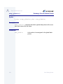
OS-9® Porting Guide
Version 2.2
Intelligent Products For A Smarter World
Copyright and Publication Information
Copyright © 1996 -1998 Microware Systems Corporation. All Rights Reserved. Reproduction of this
document, in part or whole, by any means, electrical, mechanical, magnetic, optical, chemical,
manual, or otherwise is prohibited, without written permission from Microware Systems Corporation.
This manual reflects version 2.2 of OS-9.
Revision:
Publication date:
Product Number:
B
September 1998
1030-0188
Disclaimer
The information contained herein is believed to be accurate as of the date of publication. However,
Microware will not be liable for any damages including indirect or consequential, from use of the
OS-9 operating system, Microware-provided software, or reliance on the accuracy of this
documentation. The information contained herein is subject to change without notice.
Reproduction Notice
The software described in this document is intended to be used on a single computer system.
Microware expressly prohibits any reproduction of the software on tape, disk, or any other medium
except for backup purposes. Distribution of this software, in part or whole, to any other party or on
any other system may constitute copyright infringements and misappropriation of trade secrets and
confidential processes which are the property of Microware and/or other parties. Unauthorized
distribution of software may cause damages far in excess of the value of the copies involved.
For additional copies of this software/documentation, or if you have questions concerning the above
notice, please contact your OS-9 supplier.
Trademarks
OS-9, OS-9000, DAVID, FasTrak, and UpLink are registered trademarks of Microware Systems
Corporation. SoftStax and Hawk are trademarks of Microware Systems Corporation. Windows,
Windows 95 and Windows NT are registered trademarks of Microsoft Corporation. All other product
names referenced herein are either trademarks or registered trademarks of their respective owners.
Address
Microware Systems Corporation
1500 N.W. 118th Street
Des Moines, Iowa 50325
515-223-8000
2
OS-9 Technical Manual
Ta bl e of C onte n ts
Chapter 1: Porting Steps Summary and Reference
10
15
15
15
16
17
18
19
19
20
21
22
24
25
26
26
29
30
30
32
32
35
35
9
Before Beginning the Port Steps
Porting Steps Summary
Phase I - Prepare a port directory
Phase II - Create the Low-Level System
Optional Phase III - Set Up Hawk System-State Debugging
Phase IV - Create the High-Level System
Phase V - Adding Features to the Basic Port
OS-9 Boot Code Overview
Bootstrap Code (romcore)
Low-Level System Modules
Configuration Modules
Boot Modules
Serial Communication Modules
Low-Level Network I/O Modules
Timer Modules
Debugger Modules
Notification Module
Miscellaneous Module
Low-Level System Configuration
OS-9 Boot Process Overview
Power up To the Debugger Prompt
Debugger Prompt to the Kernel Entry Point
Kernel Entry Point to the Shell Prompt
OS-9 Technical Manual
3
Chapter 2: Creating Target Port Directories
38
39
37
<MWOS>/OS9000 Ports Directory Structure
Creating Target Port Directories
Chapter 3: Porting the Boot Code
42
43
44
45
46
47
47
48
48
49
49
49
50
52
52
53
53
55
41
Porting the Bootstrap Code
The rom_cnfg.h File
Bootstrap Stack Top and Boot Module Memory
Bootstrap Memory Lists
The RAM Search
The Special Memory Search
The systype.h File
The sysinit.c File
The sysinit Entry Point
The sysinit1() Routine
The sysinit2() Routine
The sysreset() Routine
The initext Module
Configuring the Low-Level System Modules
Adding Configuration Information to systype.h
Modifying Low-Level System Module makefiles
Modifying coreboot.ml
Building the Boot Image
Chapter 4: Creating Low-Level Serial I/O Modules
58
59
61
62
75
4
57
Creating the Low-Level Serial I/O Modules
Building the Low-Level Serial I/O Modules
The Console Device Record
Low-Level Serial I/O Module Services
Starting-up the Low-Level Serial I/O Module
OS-9 Technical Manual
Chapter 5: Creating a Low-Level Ethernet Driver
78
79
79
81
92
95
103
Creating a Low-Level Ethernet Driver
Required Ethernet Driver Functions
Proto_srvr Structure
The Low-Level Ethernet Driver Entry Point Services
Additional Utility Functions
Low-Level ARP
Other Functions
Chapter 6: Creating a Low-Level Timer Module
106
108
109
114
114
77
105
Creating the Timer Module
The Timer Services Record
Low-Level Timer Module Services
Starting the Low-Level Timer Module
Building the Low-Level Timer Module
Chapter 7: Creating an Init Module
117
118 Creating an init Module
119 Init Macros
120
Optional Macros
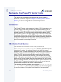
Chapter 8: Creating PIC Controllers
127
128 Reviewing the PowerPC Vector Code
128
Architecture
128
OS-9 Vector Code Service
132 Initialization
134 Interrupt Vector
134
Modifying the Interrupt Vector
136
Interrupt Controller Support
OS-9 Technical Manual
5
Chapter 9: Creating an SCF Device Driver
140
141
143
143
148
158
159
168
173
175
181
183
186
187
197
197
139
Alternatives for Creating a Console I/O Driver
Creating an SCF Driver/Descriptor
Creating SCF Device Drivers
SCF Device Driver Static Storage
SCF Device Driver Entry Subroutines
Using SCF Device Descriptor Modules
SCF Logical Unit Static Storage
SCF Logical Unit Static Storage Options
SCF Path Descriptor
SCF Path Descriptor Options Section
SCF Control Character Mapping Table
Default Mapping Table
Building SCF Device Descriptors
SCF Device Descriptor Macros
SCF Control Character Mapping
Device Specific Non-Standard Definitions
Chapter 10: Using Hardware-Independent Drivers
201
202 Simplifying the Porting Process
203 SCF Driver (scllio)
204 Virtual Console (iovcons)
204
Configuration
Chapter 11: Creating a Ticker
208
208
210
211
212
6
207
Guidelines for Selecting a Tick Interrupt Device
Ticker Support
OS-9 Tick Time Setup
Tick Timer Activation
Debugging the Ticker
OS-9 Technical Manual
Chapter 12: Selecting Real-Time Clock Module Support
213
214 Real-Time Clock Device Support
215
Real-Time Clock Support
216 Automatic System Clock Startup
217
Debugging Disk-Based Clock Modules
218
Debugging ROM-Based Clock Modules
Chapter 13: Creating RBF Drivers and Descriptors
222
224
224
225
228
230
231
231
243
244
245
250
252
258
259
261
268
Creating Disk Drivers
Understanding SCSI Device Driver Differences
Hardware Configurations
Example SCSI Software Configuration
Testing the Disk Driver
Creating RBF Device Drivers
RBF Device Driver Storage Definitions
RBF Device Driver Subroutines
Using RBF Device Descriptor Modules
Logical Unit Static Storage Initialization
Disk Drive Information
Disk Device Options
Path Descriptor Options Table
Building RBF Device Descriptors
Standard Device Descriptor Macros
RBF Specific Macro Definitions
Device Specific Non-Standard Definitions
Chapter 14: Creating Booters
270
272
280
283
287
221
269
Creating Disk Booters
The Boot Device (bootdev) Record and Services
The parser Module Services
The fdman Module Services
The scsiman Module Services
OS-9 Technical Manual
7
298 The SCSI host-adapter Module Services
303 Configuration Parameters
Appendix A: The Core ROM Services
306
307
309
314
315
325
305
The rominfo Structure
Hardware Configuration Structure
Memory Services
ROM Services
Module Services
p2lib Utility Functions
Appendix B: Optional ROM Services
337
338 Configuration Module Services
345 Console I/O Module Services
354 Notification Module Services
Appendix C: piclib.l Functions
359
360 Overview
8
Index
365
Product Discrepancy Report
405
OS-9 Technical Manual
C h ap t er 1: P o r t ing S t e p s S u m ma ry
an d R efe re n ce
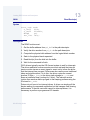
This guide walks you through the process of porting OS-9 to custom
hardware.
This chapter includes the following topics:
•
Before Beginning the Port Steps
•
Porting Steps Summary
•
OS-9 Boot Code Overview
•
OS-9 Boot Process Overview
9
1
Porting Steps Summary and Reference
Before Beginning the Port Steps
The OS-9 manuals use these terms for computer systems, in a specific
way:
host
The development system used to edit and
re-compile OS-9 source files.
target
The system to which you intend to port OS-9.
The OS-9 operating system includes the OS-9 kernel, init module,
ticker, real time clock, I/O manager, file managers, device drivers,
device descriptors, utilities, and other system modules.
Complete the following steps before you port to your target:
Step 1.
Obtain all the documentation that came with your board.
Determine the following:
a. Number of communication ports available on the target and host.
To complete installation of OS-9, you probably need one serial
port for console communication and either one serial or one
Ethernet port for debugging communications.
b. Tickers available on the target. You need one high-level,
countdown ticker for time-slicing. You need a second ticker for
low-level timing if you are using Hawk user-state debugging on
the running system.
Step 2.
Test and verify your hardware. You need:
•
The target board
•
Communication cables
•
Power supply cord
•
Hardware debugger software
Test your hardware before beginning the porting process so you are not
trying to simultaneously debug the hardware and the software. This
manual explains the steps for debugging the port of the operating
system but does not tell you how to debug hardware problems.
10
OS-9 Porting Guide
1
Porting Steps Summary and Reference
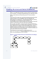
While debugging your hardware, determine if there are board hardware
features to help you in the debugging process. For example, see if there
is an LED you can light or a bell you can ring.
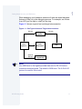
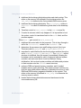
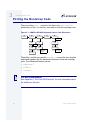
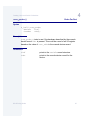
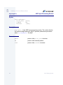
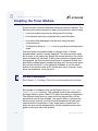
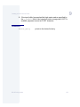
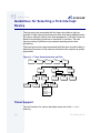
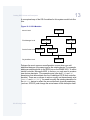
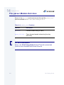
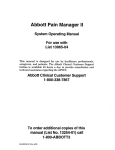
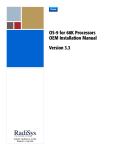
Figure 1-1 shows a typical host and target interconnection.
Figure 1-1 One Typical Host and Target Interconnection
RS-232
Host
System
Target
System
CRT/
Workstation
Optional
RS-232
RS-232
CRT
PROM
Programmer
Note
Use 9600 baud or the highest possible data rate for RS-232 links to
maximize download speed. The default is 9600 baud. The X-On/X-Off
protocol is used for flow control.
OS-9 Porting Guide
11
1
Porting Steps Summary and Reference
More In
fo More
Informatio
n More Inf
ormation M
ore Inform
ation More
-6-
Step 3.
For More Information
Refer to OS-9 for the <target> Board Guide or Getting Started with
OS-9 for <target> for other examples of how hardware can be set up.
Install Microware software distribution on host system.
Follow the installation instructions included with your Microware
software distribution media.
The distribution media contain all of the files that make-up the:
•
OS-9 boot code
•
Operating system
•
Related utilities
Some files are source code text files. Most of the other files are
makefiles and object code files. The files are organized into
subdirectories according to major subsystems (ROM, IO, CMDS, for
example) in a master directory known as the MWOS structure.
During the installation process, the file system is copied into the MWOS
directory structure. You need to use a hard disk based system with
sufficient storage capacity to contain the entire file system.
Microware has adopted this general directory structure across all of its
product lines. The files in the distribution package assume this specific
file and directory organization. They do not compile and link correctly if
the organization is different.
12
OS-9 Porting Guide
1
Porting Steps Summary and Reference
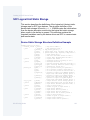
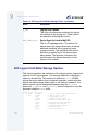
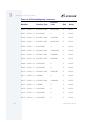
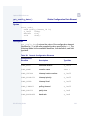
Microware uses the file name suffixes shown in the following table to
identify file types:
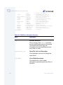
Table 1-1 Microware File Name Suffixes
Suffix
Definition
.a
Assembly language source code.
.c
C language source code.
.cc
C++ language source code.
.d
Definitions (defs) source code (for assembly).
.des
EditMod description files.
.edm
Editmod generated C header file.
.h
C header file source code.
.i
Microware intermediate code (I-code) files.
.il
Microware intermediate code libraries.
.l
Library files.
.m
Macro files.
.ml
Module list files, including coreboot.ml and
bootfile.ml, which create the boot images.
.o
Assembly language source from the compiler back end.
.r
Relocatable object code (for linker input), created by the
assembler.
OS-9 Porting Guide
13
1
Porting Steps Summary and Reference
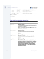
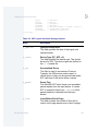
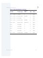
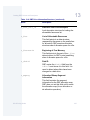
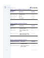
Table 1-1 Microware File Name Suffixes (continued)
Suffix
Definition
.tpl
Makefile templates.
none
Object (binary) files.
Note
In general, OS-9 does not require file name suffixes. However, certain
utilities, such as µMACS and cc or xcc, do require file name suffixes to
determine the mode of operation.
14
OS-9 Porting Guide
1
Porting Steps Summary and Reference
Porting Steps Summary
Before you begin this section, you should have completed the
pre-porting steps.
More In
fo More
Informatio
n More Inf
ormation M
ore Inform
ation More
-6-
For More Information
If you want more details about OS-9, the modules involved in the
porting process, and what occurs in OS-9 during the booting process,
see OS-9 Boot Code Overview.
Phase I - Prepare a port directory
Step 1.
Create a port directory for your board in <MWOS>/OS9000/<CPU
Family>/PORTS, where <MWOS> is the tree in which you have installed
your OS-9 product(s) and <CPU Family> is the name of the CPU
family to which the CPU on your board belongs. See Chapter 2:
Creating Target Port Directories for a full description of the MWOS
tree and the supported CPU directories.
Step 2.
Create a systype.h file by copying it from one of the example ports
directories into your working port directory. This example systype.h
file contains comments and structure that you will use, along with the
explanation in Chapter 3: Porting the Boot Code, to fully define the
board specific definitions used throughout the porting process.
Phase II - Create the Low-Level System
Step 3.
Copy the bootstrap code sources from one of the example directories
into your port directory and modify for the memory layout of your board.
Write customized startup code to initialize your board’s memory and
devices. Chapter 3: Porting the Boot Code walks you through this
process.
OS-9 Porting Guide
15
1
Porting Steps Summary and Reference
Step 4.
Create a low-level serial driver appropriate for your board’s serial
device, using the one of the example sources, and perhaps one of the
drivers included in the OS-9 for Embedded Systems source library.
This low-level serial driver provides the basic I/O service to the serial
hardware for displaying the OS-9 bootstrap message, and resident
RomBug debugging. Chapter 4: Creating Low-Level Serial I/O Modules
discusses the steps required to provide serial support for the boot code.
Note
This overview assumes that you have a serial device on your target
board.
Optional Phase III - Set Up Hawk System-State
Debugging
If you want to use sndp, or Hawk system-state debugging, instead of
RomBug for the remainder of your port, proceed with Step 5. If you
would rather continue using RomBug for system-state debugging, skip
to Step 8.
Step 5.
Step 6.
16
Create a second serial port or an Ethernet port driver to use as the
communications link for debugging.
•
To create a low-level serial driver, see Chapter 4: Creating
Low-Level Serial I/O Modules.
•
To create a low-level Ethernet driver, see Chapter 5: Creating a
Low-Level Ethernet Driver.
Create a low-level timer module to support Hawk debugging
communications. Chapter 6: Creating a Low-Level Timer Module
discusses this issue in detail.
OS-9 Porting Guide
1
Porting Steps Summary and Reference
Step 7.
Configure and test Hawk by including the following components in the
boot module list and verifying the Hawk connection:
a. The Hawk support modules
b. The low-level serial or Ethernet driver
c. The low-level timer
More In
fo More
Informatio
n More Inf
ormation M
ore Inform
ation More
-6-
For More Information
See Using Hawk for information on configuring Hawk.
Phase IV - Create the High-Level System
Step 8.
Create an initial Init module and boot image with shell as the first
executable process and term as the system console for debugging
purposes. Chapter 7: Creating an Init Module discusses the Init module
in detail.
Step 9.
(optional) Create a PIC driver for each programmable interrupt
controller on your board, if your board uses programmable interrupt
controllers. Create a library of calls that access your PIC(s) to provide a
transparent way for drivers to enable/disable interrupts on your board.
Refer to Chapter 8: Creating PIC Controllers for detailed information on
these steps.
Step 10. Write a high-level serial driver for use as your system console.
Chapter 9: Creating an SCF Device Driver walks you through the
details. If you would rather avoid writing a high-level driver for the initial
board port, see Chapter 10: Using Hardware-Independent Drivers.
If you complete the previous steps, you have completed a port to your
target board. The OS-9 shell should run on your target board as a
single-tasking operating system. Complete the following step to add
multi-tasking and time-slicing to the basic port.
Step 11. Create a system ticker to enable time-slicing and multi-processing.
See Chapter 11: Creating a Ticker for more details.
OS-9 Porting Guide
17
1
Porting Steps Summary and Reference
Phase V - Adding Features to the Basic Port
The amount of work required to complete your port depends on the
number and types of devices present on your board.
Step 12. Perform any additional porting steps, including:
a. Creating more high-level drivers for other serial ports, clocks, and
any other available devices. Clock creation and debugging is
explained in Chapter 12: Selecting Real-Time Clock Module
Support.
b. Creating high-level drivers for disk devices. Once the basic port
of a board has been completed (the first two port procedures), a
high-level driver for a floppy drive (or other device) can be
developed. Chapter 13: Creating RBF Drivers and Descriptors
discusses how to create device descriptors in detail. Once you know
this driver works, you can format a floppy disk and install an OS-9
bootfile on the floppy. At this point, you can create the low-level
driver (borrowing heavily from the tested code of the high-level
driver) to boot the system from the floppy disk. Chapter 13:
Creating RBF Drivers and Descriptors describes the steps
necessary to create and test disk drivers.
c. Creating low-level drivers and port-specific booters to boot from
the various devices available on the target. Chapter 14: Creating
Booters discusses creating disk drivers and booters in detail.
18
OS-9 Porting Guide
1
Porting Steps Summary and Reference
OS-9 Boot Code Overview
The process of booting OS-9 requires an OS-9 bootfile and boot code
that initializes the system hardware, locates the OS-9 bootfile, and
passes control to the OS-9 kernel.
The bootfile is a collection of the OS-9 system modules merged
together into a single image, with the kernel appearing as the first
module. This bootfile can exist in ROM, RAM, or flash memory. On a
disk-based system, the bootfile is on the boot disk device. Tape devices
can also be used as boot devices, with the bootfile on magnetic tape.
The boot code for OS-9 contains the raw machine-code bootstrap
routine and a collection of separately linked but inter-dependent
modules, organized as OS-9 extension modules. These modules
compose the low-level system required to boot the system and provide
debugging on the target.
Each low-level system module provides one or more services that may
be required for a particular target. By compiling these services into
separate, configurable modules, the low-level system can be rich and
flexible without inflating the memory requirements for the core bootstrap
code. You can build a minimal system by including only the low-level
system modules required for booting.
Bootstrap Code (romcore)
The bootstrap code is made from a number of different files that are
compiled and linked together to produce the final binary object code,
romcore. Some of the code is not target platform-specific and is
supplied in intermediate code form (files with .i or .il suffixes) or
relocatable object code form (files with .r or .l suffixes). To create the
bootstrap code, you need to edit a few source files. Next, you use the
make command (os9make on Windows) to compile and link these files
with the other intermediate and relocatable files to create the romcore
binary image file.
OS-9 Porting Guide
19
1
Porting Steps Summary and Reference
The bootcode follows these steps to boot OS-9:
Step 1.
Initialize the basic CPU hardware and devices to a known, stable state.
Step 2.
Locate and initialize each boot module to make all boot services
available.
Step 3.
Determine the location and extent of the target’s RAM and ROM
memory.
Step 4.
Call a system debugger if one is configured.
Step 5.
Call the configured system booter module to find the OS-9 bootfile.
Step 6.
Transfer control to the OS-9 kernel.
Low-Level System Modules
The romcore bootstrap image is merged with several low-level system
modules to produce the final boot image to be burned into PROM, or
loaded into RAM, NVRAM, or flash memory, prior to booting the target
system.
Note
romcore is the only part of the system that is not a module.
Because some of the low-level system modules provide services, they
are supplied as linked memory modules in binary form. For some
modules, both target-independent binary modules and source code are
provided so you can make target specific changes. You should use
target-independent modules for your initial port of OS-9. As more of the
port is accomplished, these modules can be rebuilt to more directly
target your system.
20
OS-9 Porting Guide
1
Porting Steps Summary and Reference
For the initial port, you need to ensure that low-level serial driver
modules exist to handle the console I/O port and an auxiliary
communications port. You may be able to use the example drivers for
the common serial devices directly. If not, the example source code
provides a guide for creating your own driver.
If you plan to use Hawk tools for downloading and remote system-state
debugging, you need to ensure an appropriate low-level network driver
is available. A low-level SLIP driver was provided for use with your serial
port. In addition, example drivers are provided for some Ethernet
devices. You use these drives directly or modify them to support your
network device.
A brief description of the distributed low-level system modules, grouped
by service follows:
Configuration Modules
You can use the configuration modules to configure the boot system.
These modules provide a way for other low-level system modules to
retrieve configuration parameters describing how they should function.
The low-level system modules are soft-coded to use the configured
values retrieved by calling the configuration module services.
cnfgdata
Target-specific data module containing the
configuration parameters. The definitions of
these parameters are set in the systype.h,
default.des (where applicable), and
config.des files.
Note
While all the other low-level system modules are organized as OS-9
extension modules, cnfgdata is an OS-9 data module.
cnfgfunc
OS-9 Porting Guide
Target-independent module that retrieves
configuration parameters from the cnfgdata
boot data module. This module could be
21
1
Porting Steps Summary and Reference
modified to return target-specific overrides of
the default information in cnfgdata. For
example, you could override cnfgdata values
with NVRAM or switch/jumper settings.
Boot Modules
These are the modules responsible for selecting the appropriate system
boot routine and using it to locate the OS-9 bootfile from the appropriate
device.
bootsys
Target-independent module providing two
services: a booter registration routine and the
booter selection/execution routine.
•The registration routine installs device specific
booter modules onto a list of available
booters as either an auto-booter or
menu-booter.
•The booter selection/execution routine is
called as part of the OS-9 booting process.
It either selects the appropriate auto-booter
or prompts you to choose a booter from the
registered menu-booters to use for booting
the system. Next, it calls that booter to
retrieve the OS-9 bootfile, passing
parameters you enter and any defaults
found for the booter in the cnfgdata
module.
portmenu
22
Target-independent module that retrieves a list
of names of configured auto and menu booters
from the configuration data module. portmenu
checks each named booter against the list of
available booters and, if found, registers it
through the bootsys registration service.
OS-9 Porting Guide
1
Porting Steps Summary and Reference
<booter>
Any of the port specific booter modules capable
of locating and loading the OS-9 bootfile from
its target device. During initialization, each
booter installs itself on a list of available
booters.
override
Target-independent booter module that enables
overriding of the autobooter. If the space bar is
pressed within 3 seconds after the bootstrap
message displays, a boot menu is displayed.
Otherwise, booting proceeds with the first
autobooter.
srecord
Target-independent booter module that
receives a Motorola S-record format file from
the communications port and loads it into
memory.
flashb
Target-independent booter support module that
assists in reprogramming flash memory.
flashb relocates the console, downloader, and
flash programming modules from flash memory
to RAM. This enables a new booter to overwrite
that flash memory location. flashb calls the
flash-specific module to program each sector,
and optionally, calls a downloader module to
read data for programming into flash memory.
romboot
Target-independent booter module that locates
the OS-9 bootfile in the special memory list.
Like all booters, romboot installs itself on the
list of available booters when initialized.
restart
Target-independent booter module that restarts
the boot process, if it is called.
rombreak
Target-independent pseudo-booter meant to
drop the system into the configured
system-state debugger.
parser
Target-independent booter support module
providing argument-value pair parsing services.
OS-9 Porting Guide
23
1
Porting Steps Summary and Reference
fdman
Target-independent booter support module
providing general booting services for RBF file
systems.
pcman
Target-independent booter support module
providing general booting services for PCF file
systems (PC FAT file systems).
scsiman
Target-independent booter support module
providing general SCSI command protocol
services.
<low-level SCSI module>
Target-specific booter support module providing
SCSI host-adaptor access services.
IDE
Target-specific standard IDE support including
PCMCIA ATA PC cards.
FDC765
PC style floppy support.
Serial Communication Modules
Two serial ports are used by the low-level system. The system console
displays boot status messages, error messages, boot menus, and
debugger messages from the target-resident debugger. The auxiliary
communications port is a download port for communicating with a host
system.
24
console
Target-independent module providing high-level
I/O hooks into the low-level entry points of the
console serial driver. The available functions
include getchar(), getc(), putchar(),
putc(), gets(), and puts().
conscnfg
Target-independent module that retrieves the
name of the low-level driver to use for the
console from the configuration data module.
After finding the driver on a list of available
drivers, conscnfg installs it as the console
serial driver. You can modify this module to
perform target-specific console configuration
instead of using a cnfgdata module.
OS-9 Porting Guide
1
Porting Steps Summary and Reference
commcnfg
Target-independent module that retrieves the
name of the low-level driver to use for the
auxiliary communication port from the
configuration module. After finding the driver on
the list of available drivers, commcnfg initializes
it as the communication serial driver. You could
modify this module to perform target-specific
communications port configuration instead of
using a cnfgdata module.
io<serial>
Any of the target-specific low-level serial
drivers. The low-level serial driver services
include device initialization and de-initialization,
read a byte, write a byte, and get status. Each
low-level serial driver will, during module
initialization, install itself on a list of available
serial drivers.
iovcons
A low-level virtual console driver that is
hardware independent because it transfers I/O
requests to the low-level network modules
(TCP/IP stack). iovcons provides a
telnetd-like interface to the low-level system
console. You can use the telnet command to
link to the target processor board to obtain a
TCP/IP connection over which the OS-9 boot
messages and RomBug I/O occurs. This
removes the need for a direct serial connection
to the target by providing a remote console.
Low-Level Network I/O Modules
protoman
Target-independent protocol module manager.
This module provides the initial communication
entry points into the protocol module stack.
lltcp
Target-independent low-level transmission
control protocol module.
llip
Target-independent low-level internet protocol
module.
OS-9 Porting Guide
25
1
Porting Steps Summary and Reference
llslip
Target-independent low-level serial line internet
protocol module. This module uses the auxiliary
communications port driver to perform serial
I/O.
lludp
Target-independent low-level user datagram
protocol module.
llbootp
Target-independent low-level BOOTP protocol
booter module.
ll<ether>
Target-specific low-level Ethernet driver
module.
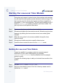
Timer Modules
The timer modules are port specific modules that use some
counter/timer device of the target to provide a polling time-out
mechanism for other low-level system modules. The services provided
are:
•
Initialization - perform any required timer initialization.
•
De-initialization - de-initialize timer.
•
Set time-out value - set a time-out value from the time of the call.
•
Get time-out value - get the time remaining until the time-out expires.
Debugger Modules
The OS-9 configuration provides for either target-resident or remote
system-state debugging, depending on the debugging method and tool
you select.
dbgentry
26
Target-independent module that provides a
hook from the boot code and OS-9 kernel’s
_os_sysdbg() system call to the low-level
debug server.
OS-9 Porting Guide
1
Porting Steps Summary and Reference
Note
dbgentry must be present in the low-level system for debugging
capability.
dbgserv
Target-independent debug server module. The
debug server contains services providing the
following debugging facilities:
•Monitoring exception vectors
•Setting breakpoints
•Setting watchpoints
•Executing at full speed (until it encounters a
breakpoint, watchpoint, or exception)
•Tracing by single instruction
•Tracing by multiple instructions
Note
The debug server must also be present in the low-level system if any
system-state debugging is required prior to the OS-9 kernel being
executed.
usedebug
OS-9 Porting Guide
Target-independent module that retrieves the
flag from the configuration data module
indicating whether the debugger is called during
system startup. You can modify this module to
perform target-specific debugger configuration
instead of using a cnfgdata module.
27
1
Porting Steps Summary and Reference
More In
fo More
Informatio
n More Inf
ormation M
ore Inform
ation More
-6-
For More Information
Refer to Using RomBug for more information about the available
features.
RomBug
Target-independent debugger client module
that provides interactive, target-resident
debugging using the serial console device for
the user interface. RomBug uses the I/O
services available through the console
module to read commands and display output,
and uses the services of dbgserv to perform
the required debugging tasks.
Note
The use of RomBug requires a low-level serial device to be available as
the system console.
sndp
28
Target-independent system-state network
debugging protocol module. This module acts
as a debugging client on the target, invoking the
services of dbgserv to perform debug tasks.
Its user interface, however, is a low-level
network connection to a Hawk client on the
development host. That is, sndp is viewed as a
debug server from the standpoint of the remote,
host-resident Hawk debugger.
OS-9 Porting Guide
1
Porting Steps Summary and Reference
Note
The use of sndp requires the appropriate low-level network driver and
protocol modules for the communication link.
More In
fo More
Informatio
n More Inf
ormation M
ore Inform
ation More
-6-
For More Information
See the Using Hawk manual for information on the features of the
Hawk debugger.
Notification Module
Hawk relies on the low-level communication modules and a network
driver for remote system-state debugging both before and after OS-9 is
up and running. Once the OS-9 system has booted, you can use either
high-level networking drivers and protocols (SPF, for example) or
low-level communications, to perform remote user-state debugging on
the target. The high-level drivers and protocols do not use the same
communications path as the low-level communications.
Regardless of the communications path, if the system drops into
system-state, the low-level drivers/protocols must be used to
communicate with the host.
Some low-level system modules require that they be informed when a
transition takes place between high and low-level states in order to do
special maintenance.
OS-9 Porting Guide
29
1
Porting Steps Summary and Reference
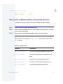
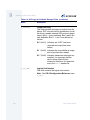
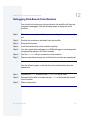
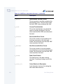
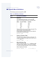
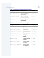
The notify module provides the following services:
Table 1-2 notify Module Services
Service
Description
Registration
Any low-level system module requiring
notification of a state change can call notify.
The calling module passes the address of a
routine to be called in the event of such a state
change, and the registration routine includes it
on a list of such routines to be called.
De-registration
A low-level system module can call notify to
cause its routine to be removed from the list of
routines to be called in the event of a state
change.
Notification
The debugger calls notify when a state
change takes place. notify passes over its list
of routines requiring notification, and calls each
in turn.
Miscellaneous Module
flshcache
Target-specific boot module that provides cache
flushing routines appropriate for the target
hardware.
Low-Level System Configuration
For each example target platform, the file coreboot.ml contains a list
of the low-level system modules along with romcore to create the boot
image. For your initial port, use the configuration given in the example
ports. You will need to change the coreboot.ml file to use the
30
OS-9 Porting Guide
1
Porting Steps Summary and Reference
appropriate low-level serial device drivers for your console and
communications ports, and the appropriate booters and low-level
communications drivers that apply to your target.
Note
You may also want to replace the target-resident RomBug debugger
with the modules appropriate for use with sndp and the remote Hawk
debugger.
OS-9 Porting Guide
31
1
Porting Steps Summary and Reference
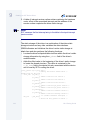
OS-9 Boot Process Overview
The booting process occurs in three phases, and are similar to the
steps you take in porting OS-9. The following sections provide
background information on porting and the phases of the boot process.
Power up To the Debugger Prompt
When power is supplied to the processor, or when a reset occurs, the
processor begins executing from a fixed address. The initial value in the
OS-9 boot code is a label, cold:. This label is defined in the bootstrap
source code file btfuncs.a.
Once btfuncs.a starts executing, it:
1. branches to the label sysinit: in the source file sysinit.c.
sysinit initializes any port specific hardware devices and then
branches back to the label sysreturn in btfuncs.a.
2. initializes the stack pointer. This relies on the memory lists defined in
the bootstrap source file rom_cnfg.h to determine the first
available RAM memory area, as well as the top-of-stack offset into it.
More In
fo More
Informatio
n More Inf
ormation M
ore Inform
ation More
-6-
For More Information
See Chapter 3: Porting the Boot Code for information on creating the
sysinit.c file and the rom_cnfg.h header file for your port.
3. calls the sysinit1() routine in sysinit.c. The sysinit1()
routine completes the initialization of target-specific hardware
devices. Before returning control back to btfuncs.a, it calls
rompak1() to determine if an initext module is present for
further hardware initialization.
32
OS-9 Porting Guide
1
Porting Steps Summary and Reference
4. initializes the bootstrap global data pointer and stack pointer. This
relies on the memory lists defined in the bootstrap source file
rom_cnfg.h to determine the first available RAM memory area.
5. initializes the bootstrap global data. The callidata() routine in
p2privte.l is called to initialize the global data for the bootstrap
code.
6. Transfers control to hard_reset() in the boot.c source file.
7. If control is returned, which only happens if it is impossible to boot
the system, control is transferred back to the cold: label, and the
process repeats.
When boot.c gets control in hard_reset() it:
1. initializes the vector table for the processor. This is done through a
call to the initvects() routine in the cbtfuncs.c file.
2. determines the processor type and floating point unit (fpu) type.
These are calls to getfpu() and getcpu() in btfuncs.a.
3. searches for and initializes the low-level system modules through a
call to rominfo_control() in romsys.l. The rominfo record
structure is initialized, then the memory immediately following the
bootstrap code is searched for valid, contiguous low-level system
modules, and each one that is found is initialized. During
initialization, the low-level system modules add tables and pointers
to their services onto the rominfo record structure.
4. performs RAM and special memory searches, and if needed,
enables memory parity checking. The memory search routines use
both bus errors and pattern matching to determine the sizes of valid
RAM and ROM memory segments available on the system. This
relies on the memory list defined in rom_cnfg.h to determine the
memory areas to search.
5. inserts the bootstrap global data area and stack area into the
consumed memory list.
OS-9 Porting Guide
33
1
Porting Steps Summary and Reference
6. Calls the sysinit2() routine in sysinit.c. The sysinit2()
routine performs any target-specific initialization that relies on the
completion of the previous steps. There may not be any, but before
sysinit2() returns, it calls rompak2() to determine if an
initext module is present for further target-specific initialization.
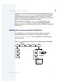
7. Initiates the configured low-level debugger by calling the
sysboot_control() routine from romsys.l. If a low-level
debugger is configured, enabled, and available, it is called at this
point by the sysboot_control() function. The debugger displays
a processor register display, and a prompt.
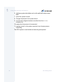
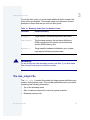
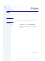
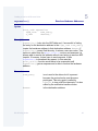
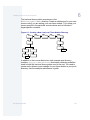
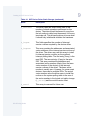
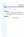
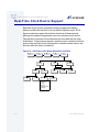
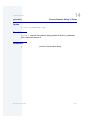
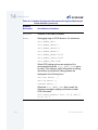
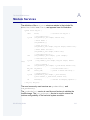
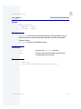
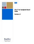
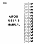
The major steps of this phase are shown in Figure 1-2. The following
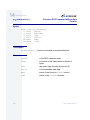
figure illustrates the first step in the boot process:
Figure 1-2 Chart of Files and the Subroutines they Contain
btfuncs.a
boot.c
cold:
...
bsysinit
sysreturn
...
bl sysinit1()
sysinit.c
low-level
system-state
debugger
module
initext.c
(if present)
sysinit:
b sysreturn
sysinit1()
...
rompak1()
return()
rompak1()
return()
sysinit2()
rompak2()
return()
rompak2()
return()
...
bl hard_reset
hard_reset()
...
sysinit2()
...
sysboot_control()
34
At debugger
prompt
OS-9 Porting Guide
1
Porting Steps Summary and Reference
Debugger Prompt to the Kernel Entry Point
On return from the debugger (once you have requested booting be
continued) the bootstrap code:
1. calls the boot system to find the OS-9 bootfile.
sysboot_control() invokes the boot service provided by the
bootsys module to oversee the location of the OS-9 bootfile by the
configured booter(s). This boot service calls each registered
auto-booter in turn until one is successful in locating a valid OS-9
bootfile. If there are no auto-booters, or if all fail to find a bootfile,
you are presented with a menu listing of all registered menu-booters
and prompted to select one. The specified booter is called and the
process is repeated until a selected booter is successful in locating
an OS-9 bootfile.
2. transfers control to the OS-9 kernel. The coldstart entry point of the
kernel module is calculated and control is transferred to the kernel
for completion of the boot.
Kernel Entry Point to the Shell Prompt
The kernel’s coldstart routine finishes the task of booting OS-9. It reads
the OS-9 configuration module, init, and using the system
configuration data stored within the kernel:
1. initializes system global data (commonly referred to as the system
globals).
2. adds the colored memory list to the memory lists found by the
bootstrap code.
3. builds the kernel’s RAM memory from the RAM memory list.
4. builds the module directory by searching for modules in the special
memory list.
5. executes all configured extension modules from the PREIO
extensions list.
OS-9 Porting Guide
35
1
Porting Steps Summary and Reference
6. initializes system data tables such as the path table and process
table.
7. opens the system console.
8. changes directories to the system device.
9. executes all configured extension modules from the EXTENS
extension list.
10. creates the first process to be executed.
11. transfers control to the system execution loop to begin process
scheduling.
The OS-9 system is now booted and executing as expected.
36
OS-9 Porting Guide
Cha pt e r 2 : C re a t in g Ta r g e t P o r t
D ir e ct o ri es
This chapter includes the following topics:
•
<MWOS>/OS9000 Ports Directory Structure
•
Creating Target Port Directories
37
2
Creating Target Port Directories
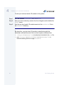
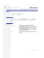
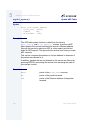
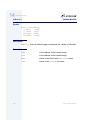
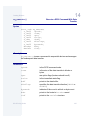
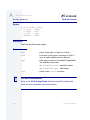
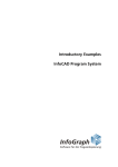
<MWOS>/OS9000 Ports Directory Structure
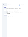
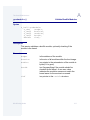
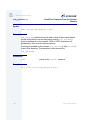
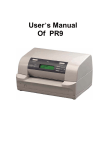
The following figure shows only the directories referred to in this guide.
The MWOS structure includes other directories and files. For a list of
files and directories included in your software distribution, refer to your
Getting Started With OS-9 for <target>, Getting Started With OS-9
for Embedded Systems, or Getting Started With OS-9 for Wireless
Systems.
Figure 2-1 <MWOS>/OS9000 Porting Directories and Files
<Target>
BOOTS
INIT
PICLIB
CMDS
LIB
RBF
SCF
PIPE
ROM
UTILS
SYSMODS
BOOTOBJS
IRQS
TICKER
ROM
RTC
CNFGDATA
COMMCNFG
CNFGFUNC
EMBEDDED
INITEXT
IO<nnnn>
COMSCNFG
EXAMPLES
(optional)
SYSTEMS
<others>
PORTBOOT
II<nnnn>
ROMCORE
PORTMENU
USEDEBUG
TMR<nnnn>
TESTBOOT
(optional)
makefile
coreboot.ml
bootfile.ml
readme.txt
config.des (where
applicable)
38
OS-9 Porting Guide
2
Creating Target Port Directories
Creating Target Port Directories
The OS-9 boot code sources, driver sources, and system modules
(such as the kernel) consist of many files when installed on your
system.
Microware provides example source files for several different types of
device drivers, including serial, tickers, and real-time clocks. You only
need support for the hardware platform your target has available so you
can ignore drivers that are not relevant.
Step 1.
Determine the following hardware information before beginning the
porting procedure:
•
What I/O devices will you use?
•
How are these devices mapped into memory?
•
How is the memory organized?
•
What does the memory map of the entire system look like?
Step 2.
Create your own working directory structure in which to design and
build your port. Start by creating a subdirectory in MWOS/OS9000/
<CPU Family>/PORTS. (<CPU Family> is a specific processor
family directory like PPC or 80386.) This is the root of your target
platform's directory structure. If your target platform is based on a
processor for which there already exists a processor-specific ports
directory, then your target directory can be created there instead. For
example, if your target system is built on a PowerPC 603 CPU, you
could choose to develop your port in MWOS/OS9000/603/PORTS.
Step 3.
Create the necessary directories for your target and copy the following
files from the corresponding directories in on the example ports as a
starting point. Each target port directory structure is somewhat different
depending upon the configuration of the target platform.
• BOOTS/SYSTEMS/PORTBOOT
• CMDS/BOOTOBJS/ROM
• ROM/CONSCNFG/makefile
OS-9 Porting Guide
39
2
Creating Target Port Directories
• ROM/COMMCNFG/makefile
• ROM/PORTMENU/makefile
• ROM/USEDEBUG/makefile
• ROM/ROMCORE/RELS
• ROM/ROMCORE/makefile
• ROM/makefile
The BOOTS/SYSTEMS/PORTBOOT/coreboot.ml file contains the list
of names of modules to be merged with rom when building the boot
image.
The makefile in ROM invokes the makefiles in each of its appropriate
subdirectories to build the bootstrap code and low-level system
modules. Some of the subdirectories are disabled by default. For the
initial target port, uncomment the values for the CONSCNFG, COMMCNFG,
PORTMENU, and USEDEBUG macros.
Once this target port directory structure is in place, the bootstrap code
can be ported.
40
OS-9 Porting Guide
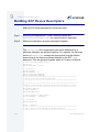
C ha pt e r 3 : Po rti n g th e Bo o t C o d e
This chapter includes the following topics:
•
Porting the Bootstrap Code
•
Configuring the Low-Level System Modules
•
Building the Boot Image
41
3
Porting the Boot Code
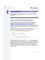
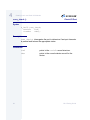
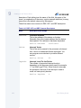
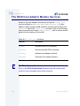
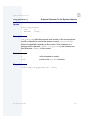
Porting the Bootstrap Code
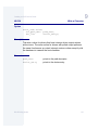
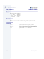
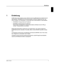
The source files, boot.c and all of the files in the <CPU Family>
subdirectory of the ROM directory, are used to build the bootstrap code.
Figure 3-1 <MWOS>/OS9000 Bootstrap Source Code Directories
MWOS
OS9000
<CPU Family>
PORTS
<Target>
systype.h
SRC
LIB
ROM
boot.c
ROM
<CPU Family>
ROM
p2lib.l
p2private.l
romsys.l
ROMCORE
sysinit.c
rom_cnfg.h
These files, and the port-specific sysinit.c source file, are compiled
and linked together with the distributed libraries to build the bootstrap
code. The distributed libraries include:
• p2privte.l
• p2lib.l
• romsys.l
More In
fo More
Informatio
n More Inf
ormation M
ore Inform
ation More
-6-
For More Information
See Appendix A: The Core ROM Services, for more information about
the distribution libraries.
42
OS-9 Porting Guide
3
Porting the Boot Code
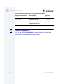
To port the boot code, you must create additional files to support the
source files and libraries. The sample target port directories contain
examples of these files that you can use as a guide.
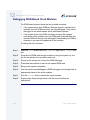
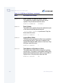
Table 3-1 Bootstrap Code Files You Need to Create
!
File Name
Content Summary
systype.h
Target system, hardware-dependent definitions.
rom_cnfg.h
The bootstrap memory list and stack definitions.
ROM console and boot device record definitions
and the ROM memory lists.
sysinit.c
Target specific hardware initialization your system
may require following a system reset.
WARNING
Do not modify the other bootstrap source code files. If you alter these
files, the port code may not function correctly.
The rom_cnfg.h File
The rom_cnfg.h header file contains the target system definitions only
used for the bootstrap code. This includes patchable memory locations
containing the following information:
•
Top of the bootstrap stack
•
Size of memory reserved for low-level system modules
•
Bootstrap memory lists
OS-9 Porting Guide
43
3
Porting the Boot Code
More In
fo More
Informatio
n More Inf
ormation M
ore Inform
ation More
-6-
For More Information
Some processors may require additional steps. See your Getting
Started With OS-9 for <target> for your processor-specific porting
information.
Bootstrap Stack Top and Boot Module Memory
The bootstrap code allocates memory from the first RAM memory
segment of the system into three parts, as shown in Figure 3-1
<MWOS>/OS9000 Bootstrap Source Code Directories. The
bootstrap code allocates the global data area and the stack area for its
own use. It reserves the special memory pool for the low-level system
modules to use.
The definitions for the size of the bootstrap stack area (ROMStackSz)
and the boot module memory pool (ResvMemSz) are given in
rom_cnfg.h as shown in the following example:
_asm("
ROMStackSz equ $4000 KB
ResvMemSz equ $20000 128KB
romstack:
dc.l _dsize+ResvMemSz+ROMStackSz
dc.l ROMStackSz size of ROM stack
");
The linker produces a link map for the romcore bootstrap image when
it is built. Using this map, the offset of romstack can be found. Once
this address is known, a 32-bit value at that address can be patched to
change the size of the memory area reserved for low-level system
modules. Additionally, by patching in the proper 32-bit values at that
address, and the following address, the size of the bootstrap stack area
can be changed.
44
OS-9 Porting Guide
3
Porting the Boot Code
Figure 3-2 shows the memory diagram of this first RAM segment.
Figure 3-2 First RAM Memory Segment Allocated by the Bootstrap Code
bootstrap global data
_dsize
low-level system module
reserved memory
ResvMemSz
bootstrap stack
ROMStackSz
Initial Bootstrap Stack Top
Bootstrap Memory Lists
The ROM memory list is made of pairs of 32-bit integers specifying start
and end boundaries for memory lists. The first list is used to map the
system’s available RAM memory. The second list is used to map
special memory regions treated as ROM memory and searched in a
non-destructive fashion. Special memory areas may include ROM,
flash, or NVRAM memory. For example:
/*
*memory search list
*/
_asm(“
memlist
dc.l $4000,$80000 first memory segment includes
ROM data area and stack
dc.l $400000, $1000000 second memory segment
dc.l 0
dc.l $fff40000, $fff80000 ROM search area
dc.l 0,0,0,0,0 extra fields for patching lists
“);
OS-9 Porting Guide
45
3
Porting the Boot Code
In this example the bootstrap code:
1. Uses RAM from the beginning of the first memory segment for its
data area and stack. (The PowerPC vectors are initialized at
$0-$4000.)
2. Searches for RAM memory following its stack to $80000.
3. Searches for RAM memory in the range $400000 to $1000000.
The next zero word terminates the RAM search list.
The ROM search list follows the RAM search list. In this example, the
ROM search list causes the bootstrap code to search for ROM memory
between $FFF40000 and $FFF80000.
These memory lists are used by the boot.c source file when it builds a
table of available memory. Each list is searched for valid memory
segments, and each valid segment is added to the memory table.
The RAM Search
The first part of the search list defines the areas of the address space
where the bootstrap code should normally search for RAM memory.
This reduces the time it takes for the system to perform the search. It
also prevents the search (and also OS-9) from accessing special use or
reserved memory areas such as I/O controller addresses or graphics
display RAM.
The first entry, or bank, in this list must point to a block of RAM large
enough for storing:
•
Bootstrap global data
•
Memory required by the low-level system modules
•
Start-up bootstrap stack
•
System global data
If the system boots from a disk or another device, the first bank needs
to be large enough to also hold the size of the bootfile loaded from that
device, as well as any buffers required by the boot drivers.
46
OS-9 Porting Guide
3
Porting the Boot Code
The RAM memory search is performed on each area in the search list
by:
1. Reading the first four bytes of every 8K memory block of the area.
2. Writing a test pattern sequence. Memory is initialized to repetitions
of the pattern, Dude (0x44756465).
3. Reading the area again for comparison. If the read matches what
was written, the search assumes this was a valid RAM block and is
added to the system free RAM list.
The Special Memory Search
The second part, or the special memory part of the search list, is strictly
a non-destructive memory search. This is necessary so that the
memory search does not overwrite modules downloaded into RAM or
NVRAM.
During the porting process, you should temporarily include enough
RAM (at least 256K) in the special memory list to download parts of the
boot file. If this download area has parity memory, you may need to do
one of the following:
•
Manually initialize it.
•
Disable the CPU’s parity, if possible.
•
Include a temporary routine in the sysinit.c file.
The RAM and special memory searches are performed by boot.c
during the booting process.
The systype.h File
The systype.h file is an include file used in building several of the
low-level system modules and OS-9 system modules. This file should
be viewed as the common location for all port specific hardware
definitions and configuration parameters.
OS-9 Porting Guide
47
3
Porting the Boot Code
The main sections of the systype.h file include:
•
Ticker and real time clock definitions
•
Low-level system module configuration definitions
•
Hardware specific macros and definitions
For support of the bootstrap code, it is important to include in the
systype.h header file any target-specific hardware definitions you
want to use as you write the hardware initialization routines in the
sysinit.c source file. Such definitions might include hardware
specific bit layouts, address offsets, or initial values.
The sysinit.c File
The sysinit.c file should contain all special hardware initialization
your system requires after a reset or system reboot. The sysinit.c
file consists of these different sections, or entry points:
• sysinit
• sysinit1
• sysinit2
• sysreset
The sysinit Entry Point
The first entry point, sysinit, is called almost immediately after a
reset by btfuncs.a. sysinit performs the minimum hardware
actions the system may require to enable memory or initialize
necessary devices during start up.
This routine does not return through the typical return machine
instruction. The return to btfuncs.a is made directly by a branch to
the sysreturn: label.
The sysinit routine is always a complete embedded assembly
routine.
48
OS-9 Porting Guide
3
Porting the Boot Code
!
WARNING
At this point, the stack register has not been initialized to point to a
stack area. The sysinit code must be written assuming no stack
exists.
The sysinit1() Routine
The first C-routine, sysinit1() completes any necessary hardware
initialization that was not required to be done by the sysinit assembly
routine. In addition, it makes the call to rompak1() to activate any
initialization routines in the initext module (described later in this
section).
While a stack is present during sysinit1() execution, no static
storage is available.
The sysinit2() Routine
The second C-routine, sysinit2(), is used for any system
initialization required after calling sysinit1(). Often, this routine
consists of a routine that calls rompak2() and returns, as most
systems can perform all their required initialization during the first call to
sysinit and sysinit1(). sysinit2() is called after funcs.a and
boot.c have:
•
initialized the vector table (for vectors in RAM) and the exception
jump table.
•
performed the memory searches.
The sysreset() Routine
The third C-routine, sysreset(), is installed as a service to enable the
low-level system modules, in particular the low-level debugger, a way of
initiating a software reset on the target. sysreset() performs any
OS-9 Porting Guide
49
3
Porting the Boot Code
special hardware actions the system requires before attempting a
software reset, for example a cache flush. It then initiates the proper
instructions to reset the system, or if such a reset is not supported by
the target, branches back to the Cold: entry point in btfuncs.a to
initiate the reboot sequence.
The initext Module
The initext module is a separately linked portion of hardware
initialization code providing a modular functional extension to the
sysinit1() and sysinit2() routines described previously.
It is provided in source form, enabling an end-user to add hardware
initialization routines specific to a target configuration that would be
inappropriate to include in the base romcore module because of
hardware modularity requirements. For example, a peripheral device
implemented on a card plugged into the host bus may require specific
initialization immediately following a CPU reset in the case where a bus
reset could not be asserted by the processor in the sysreset()
routine described above. This initialization code might be appropriately
implemented in the initext module rather than a romcore module,
since the end-user may have obtained the port from an OEM providing
the base target platform.
There are two entry points to the initext module, rompak1() and
rompak2(). When the initext module is present in the system
immediately following the romcore module, rompak1() would be
executed by sysinit1(), and rompak2() would be executed by
sysinit2(), provided those routines attempt to call the rompak
routines.
50
OS-9 Porting Guide
3
Porting the Boot Code
Note
Note the following:
• rompak1() is executed prior to ROM module scan.
• rompak2() is executed after ROM module scan and all ROM
modules have been painted.
• No static storage is available for the initext module.
The initext module is built in a ROM/INITEXT subdirectory within
the target port directory. You should defer implementation of your base
initext module until after your initial port is completed. When you
decide to start on your initext module, use the sources and makefile
from an example port as a reference.
OS-9 Porting Guide
51
3
Porting the Boot Code
Configuring the Low-Level System Modules
Once the bootstrap code is ported and your low-level serial I/O drivers
are ready, you need to provide some configuration data to define what
your initial port looks like.
The OS-9 booting process relies on the use of a configuration data
module (cnfgdata) to define certain default parameters used in the
boot. The configuration data module provides for great flexibility in
designing your system, but is not required for a simple port. We
recommend you keep your initial port as simple as possible.
If you are planning to use the Hawk remote debugger during the porting
process, you must use the configuration data module. Read carefully
about the configuration module and the low level network configuration
before attempting such a port.
For the simple port using the target resident RomBug debugger, you do
not need a configuration module. Configuring the simple port involves:
1. Adding to systype.h the definitions the low-level system modules
use as default configuration values for system console and
communications ports.
2. Modifying the boot module makefiles to disable use of the
configuration data module for the first port stage.
3. Modifying the boot module list found in coreboot.ml to reflect the
low-level system modules required for your system.
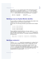
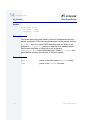
Adding Configuration Information to systype.h
systype.h should be modified to include definitions for the symbols
CONSNAME and COMMNAME.
52
OS-9 Porting Guide
3
Porting the Boot Code
The symbol CONSNAME gives the name of the console device record
that the console configuration module (conscnfg) will, by default,
select for use as the system console. Similarly, COMMNAME is used by
commcnfg as the default for the communication port. For example:
#define CONSNAME
#define COMMNAME
COMM1NAME
"MVME1603:com2"
Modifying Low-Level System Module makefiles
For your initial port, disable use of the configuration data module. Later
chapters discuss how to build and use this module.
Modify each of the following makefiles copied earlier from an example
port.
<Target>/ROM/COMMCNFG
<Target>/ROM/CONSCNFG
<Target>/ROM/PORTMENU
<Target>/ROM/USEDEBUG
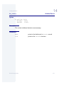
These makefiles contain the definition of a macro called SPEC_COPTS
that is defined to include the C option -dUSECNFGDATA. Comment this
option out of the macro definition. For example, change the first line into
the second line:
SPEC_COPTS = -d<option1> -d<option2> -dUSECNFGDATA
SPEC_COPTS = -d<option1> -d<option2> #-dUSECNFGDATA
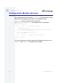
Modifying coreboot.ml
The file coreboot.ml, copied from an example port, contains a list of
low-level system modules included in the boot image when it is built.
To finish the configuration of your initial port, use the asterisk (*) to
comment out the use of the configuration modules cnfgdata and
cnfgfunc, and replace the low level I/O modules names in this list with
the ones appropriate for your target. The I/O modules used in the
example ports are usually named io<device>.
OS-9 Porting Guide
53
3
Porting the Boot Code
Do not remove the console, conscnfg, or commcnfg module names,
and be sure to add the appropriate low-level serial I/O module names
after console, but before the conscnfg or commcnfg module names.
Note
Once the new port is proven, the console and communication ports can
be removed if desired.
!
WARNING
Do not change the order of the low-level system module names or the
system may not boot.
54
OS-9 Porting Guide
3
Porting the Boot Code
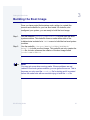
Building the Boot Image
Once you have ported the bootstrap code, written (or copied) the
sources and makefile for your low level serial I/O modules, and
configured your system, you are ready to build the boot image.
Step 1.
Use the makefile <Target>/ROM/makefile to build your low-level
system modules. This makefile forces a make within each of the
subdirectories included in its TRGTS macro to build the low-level system
modules.
Step 2.
Use the makefile <Target>/BOOTS/SYSTEMS/PORTBOOT/
makefile to build your boot image. This makefile not only creates the
rom file, but also oversees the creation of the boot image called
coreboot or os9kboot.
Note
You may get errors when running make. If these problems are not
related to low-level system modules, you can ignore the errors. This is
because you only need the coreboot file for testing and it is created
before the make exits with errors while trying to build the rom file.
OS-9 Porting Guide
55
3
Porting the Boot Code
56
OS-9 Porting Guide
Ch a pt e r 4 : C r ea t in g L o w - L e v el S e ri a l
I /O M odul es
This chapter includes the following topics:
•
Creating the Low-Level Serial I/O Modules
•
The Console Device Record
•
Low-Level Serial I/O Module Services
•
Starting-up the Low-Level Serial I/O Module
57
4
Creating Low-Level Serial I/O Modules
Creating the Low-Level Serial I/O Modules
While it is not absolutely necessary to have a serial I/O console device
on your system, it is strongly recommended that your initial port include
both a console device and an auxiliary serial I/O communications
device.
The console I/O routines are used by the bootstrap code and low-level
system modules for error messages, and by the debugger and
menu-booters for interactive I/O. The communications port is used by
the debuggers as a download and talk-through port. The
communications port can also be used as the SLIP device for low level
network communications with the Hawk remote debugger.
Source code is provided for several low-level serial modules that you
can configure and use in your system without modification. If your target
has a serial device for which no I/O module already exists, use the
example sources as a guide to write your own. If both the console port
and communications port use the same type of hardware interface, you
only need to build one low-level I/O module.
The distributed low-level serial I/O module sources are in
MWOS/SRC/ROM/SERIAL. Create a subdirectory for your own source
code if you are building your own I/O module.
Figure 4-1 Low-Level Serial I/O Source Code Directories for Creating a
Module
MWOS
OS9000
SRC
<CPU Family>
PORTS
<Target>
ROM
IO<nnnn>
58
DEFS
ROM
HW
SERIAL
OS-9 Porting Guide
4
Creating Low-Level Serial I/O Modules
In addition to the directories listed earlier, each example port directory
contains <Target>/ROM/IO<nnnn> directories containing makefiles
used to build the low-level I/O module used in the port. You need to
create such a directory and makefile for your serial devices in your ports
directory. Use the example makefiles as a guide.
Device specific include files (<xxxx>.h) are normally kept in the
MWOS/SRC/DEFS/HW directory. These are typically chip-specific
definitions and are to be shared by both low-level (ROM) and high-level
(OS) drivers.
Building the Low-Level Serial I/O Modules
The makefile for your I/O module should be created in a properly
named subdirectory of your ports ROM directory (for example,
<Target>/ROM/IO<nnnn>). Use the makefiles from the example
ports as a guide.
Figure 4-2 Low-Level Serial I/O Source Code Directories for Building a
Module
MWOS
OS9000
<CPU Family>
PORTS
<Target>
SRC
BOOTS
ROM
makefile
ROM
SYSTEM
IO<nnnn>
SERIAL
PORTBOOT
makefile
coreboot.ml
bootfile.ml
config.des (where
applicable)
OS-9 Porting Guide
59
4
Creating Low-Level Serial I/O Modules
To add your low-level serial I/O module to the system:
Step 1.
Edit the makefile, <Target>/ROM/makefile.
Step 2.
Add your device directory name to the list of targets used to define the
TRGTS macro.
Step 3.
Add the low-level serial I/O module name into the corboot.ml file in
the PORTBOOT directory.
By doing this, your low level I/O module is rebuilt along with the
bootstrap code and the rest of the low-level system modules when:
60
•
<Target>/ROM/makefile is invoked and included in the rom file,
•
and, <Target>/BOOTS/SYSTEMS/PORTBOOT/makefile is
invoked creating the boot image coreboot.
OS-9 Porting Guide
4
Creating Low-Level Serial I/O Modules
The Console Device Record
A console device (consdev) record is maintained for each low level
serial I/O device included with the low-level system modules. This
record is used to access the services of the I/O module, and to maintain
lists of such devices. The definition of consdev appears in the header
file, rom.h, and appears here for illustration.
Figure 4-3 Console Device Record Directory
MWOS
SRC
<DEFS
Family>
ROM
rom.h
struct consdev {
idver
infoid;
void
*cons_addr;
u_int32 (*cons_probe)(Rominfo, Consdev),
(*cons_init)(Rominfo, Consdev),
u_char
u_int32
u_int32
u_int32
u_char
u_int32
u_char
void
void
Consdev
u_int32
int
/*
/*
/*
/*
/*
/*
structure version tag */
port address of I/O device*/
h/w probe service */
initialization */
service */
(*cons_term)(Rominfo, Consdev);
de-initialization service*/
(*cons_read)(Rominfo, Consdev);
/* read service */
(*cons_write)(char, Rominfo, Consdev),
/* write service */
(*cons_check)(Rominfo, Consdev);
/* character check service */
(*cons_stat)(Rominfo, Consdev, u_int32),
(*cons_irq)(Rominfo, Consdev),
(*proto_upcall)(Rominfo, void*, char*);
cons_flags;
/* device flags */
cons_csave,
/* read ahead stash */
cons_baudrate,
/* communication baud rate */
cons_parsize,
/* parity, data bits, stop bits */
cons_flow;
/* flow control */
cons_vector,
/* interrupt vector */
cons_priority,
/* interrupt priority */
poll_timeout;
*cons_abname,
/* abreviated name */
*cons_name;
/* full name and description */
*cons_data;
/* device specific data */
*upcall_data;
cons_next;
/* next serial device in list*/
cons_level;
/* interrupt level */
reserved;
};
OS-9 Porting Guide
61
4
Creating Low-Level Serial I/O Modules
Low-Level Serial I/O Module Services
The following entry points describe the services required of each
low-level serial I/O module to support the booting process.
Table 4-1 Entry Points
62
Function
Description
cons_check()
Check I/O Port
cons_init()
Initialize Port
cons_irq()
Polled Interrupt Service Routine for
I/O Device
cons_probe()
Probe for Port
cons_read()
Read Character from I/O Port
cons_stat()
Set Status on Console I/O Device
cons_term()
De-initialize Port
cons_write()
Write Character to Output Port
notification_handler()
Handle Callback from Notification
Services
OS-9 Porting Guide
4
Creating Low-Level Serial I/O Modules
More In
fo More
Informatio
n More Inf
ormation M
ore Inform
ation More
-6-
For More Information
Refer to the OS-9 Porting Guide Windows® help file included with
Hawk for more information about these functions.
OS-9 Porting Guide
63
4
Creating Low-Level Serial I/O Modules
cons_check()
Check I/O Port
Syntax
u_int32 cons_check(
Rominfo
rinf,
Consdev
cdev);
Description
cons_check() interrogates the port to determine if an input character
is present and returns the appropriate status.
Parameters
64
rinf
points to the rominfo record structure.
cdev
points to the console device record for the
device.
OS-9 Porting Guide
4
Creating Low-Level Serial I/O Modules
cons_init()
Initialize Port
Syntax
u_int32 cons_init(
Rominfo
rinf,
Consdev
cdev);
Description
cons_init() initializes the port. It resets the device port, sets up for
transmit and receive, and sets up baud rate, parity, bits per type, and
number of stop bits. cons_init() also registers a notification handler
described below, with the notification services.
Parameters
rinf
points to the rominfo record structure.
cdev
points to the console device record for the
device.
OS-9 Porting Guide
65
4
Creating Low-Level Serial I/O Modules
cons_irq()
Polled Interrupt Service Routine for I/O
Device
Syntax
u_int32 cons_irq(
Rominfo
rinf,
Consdev
cdev);
Description
cons_irq() is an interrupt service routine installed for the device
performing the following polling interrupt service on receipt of a device
interrupt:
Step 1.
Disables further interrupts on the device.
Step 2.
Clears the interrupt from the device.
Step 3.
Initializes the low-level polling timer.
Step 4.
Sets the polling time-out value and loops through the process of
checking the device and timer until either a character is received or the
time-out occurs.
Step 5.
Sends a character that is received up the protocol stack by calling the
uplink routine installed in the console device structure.
Step 6.
Repeats steps 2 through 5 until a time-out occurs.
Step 7.
Re-enables device interrupts and returns.
Parameters
66
rinf
points to the rominfo record structure.
cdev
points to the console device record for the
device.
OS-9 Porting Guide
4
Creating Low-Level Serial I/O Modules
cons_probe()
Probe For Port
Syntax
u_int32 cons_probe(
Rominfo
rinf,
Consdev
cdev);
Description
cons_probe() tests to see if the hardware described by the console
device record cdev is present. This could be a read of an I/O register
based on the value of cons_addr in the console device record.
Parameters
rinf
points to the rominfo record structure.
cdev
points to the console device record for the
device.
OS-9 Porting Guide
67
4
Creating Low-Level Serial I/O Modules
cons_read()
Read Character From I/O Port
Syntax
u_char cons_read(
Rominfo
rinf,
Consdev
cdev);
Description
cons_read() returns a character from the device’s input port.
cons_read() repeatedly calls cons_check() until a character is
present. cons_read() should not echo the character. The only special
character handling it might perform is XON-XOFF processing if the
CONS_SWSHAKE flag is set in the cons_flow field of the console
device structure.
Parameters
68
rinf
points to the rominfo record structure.
cdev
points to the console device record for the
device.
OS-9 Porting Guide
4
Creating Low-Level Serial I/O Modules
cons_stat()
Set Status on Console I/O Device
Syntax
u_int32 cons_stat(
Rominfo
rinf,
Consdev
cdev,
u_int32
code);
Description
cons_stat() changes the operational mode of the I/O module.
Parameters
rinf
points to the rominfo record structure.
cdev
points to the console device record for the
device.
code
is the low-level setstat code indicating
operational mode change. The supported
setstat codes are defined in
MWOS/SRC/DEFS/ROM/rom.h and described
as follows:
CONS_SETSTAT_POLINT_OFF
Indication
Issued when hlproto no longer requires the
services of the communications port.
Operation
Disable receive interrupts on port.
CONS_SETSTAT_POLINT_ON
Indication
OS-9 Porting Guide
Issued when hlproto requires the services of
the communications port for user-state
connections.
69
4
Creating Low-Level Serial I/O Modules
Operation
Verify configuration of low-level timer, enable
receive interrupts on port.
CONS_SETSTAT_ROMBUG_OFF
Indication
Issued indirectly through notification services
when the RomBug debug client returns control
from any breakpoint, exception, or
d_sysdebug entry.
Operation
Restore any applicable port- or chip-specific
configuration (including interrupts).
CONS_SETSTAT_ROMBUG_ON
Indication
Issued indirectly through notification services
when the RomBug debug client gets control on
any breakpoint, exception, or d_sysdebug
entry.
Operation
Save any applicable port- or chip-specific
configuration (including interrupts). Disable any
receive interrupts on port.
CONS_SETSTAT_RXFLOW_OFF
Indication
Issued when a driver user (such as llslip)
needs to restrict the flow of received data.
Operation
If hardware handshaking is configured, assert
hardware flow control (on), otherwise if software
handshaking is configured, send an X-OFF.
CONS_SETSTAT_RXFLOW_ON
Indication
70
Issued when a driver user (such as llslip)
needs to restore the flow of received data.
OS-9 Porting Guide
4
Creating Low-Level Serial I/O Modules
Operation
OS-9 Porting Guide
If hardware handshaking is configured, turn off
hardware flow control, otherwise if software
handshaking is configured, send an X-ON.
71
4
Creating Low-Level Serial I/O Modules
cons_term()
De-initialize Port
Syntax
u_int32 cons_term(
Rominfo
rinf,
Consdev
cdev);
Description
cons_term() shuts the port down by disabling transmit and receive.
Parameters
72
rinf
points to the rominfo record structure.
cdev
points to the console device record for the
device.
OS-9 Porting Guide
4
Creating Low-Level Serial I/O Modules
cons_write()
Write Character To Output Port
Syntax
u_int32 cons_write (
char
c,
Rominfo
rinf,
Consdev
cdev);
Description
cons_write() writes a character to the output port with no special
character processing (for a low-level serial driver that does not use
software handshaking).
The sample sources also contain the following serial I/O module entry
points to support the user state Hawk remote debugger. For the initial
port, it is not necessary to include these entry points because the
previous functions are sufficient for support of system-state operation at
the low-level. The following entry points support the use of low-level
serial I/O module while in user state after the system is booted. This
functionality is required for use of the I/O module by the user-state
Hawk debugger.
Parameters
c
is the character written to the output port.
rinf
points to the rominfo record structure.
cdev
points to the console device record for the
device.
OS-9 Porting Guide
73
4
Creating Low-Level Serial I/O Modules
notification_handler()
Handle Callback from Notification Services
Syntax
u_void notification_handler(
u_int32
direction,
void
*cdev);
Description
notification_handler issues calls to cons_stat() with the
CONS_SETSTAT_ROMBUG_ON and CONS_SETSTAT_ROMBUG_OFF
codes.
Parameters
74
direction
is the direction value provided from the
notification services: the NTFY_DIR_TOROM
value indicates a transition into the ROM from
the operating system, the NTFY_DIR_TOSYS
values indicates a transition to the operating
system from the ROM.
cdev
points to the console device structure for the
device.
OS-9 Porting Guide
4
Creating Low-Level Serial I/O Modules
Starting-up the Low-Level Serial I/O Module
During the early stages of system bootup, the bootstrap code searches
for and initializes all low-level system modules included in the boot
image. The initialization entry point for the low-level system modules is
supplied in a relocatable (.r) file. This entry point branches to the C
function p2start() which you need to provide for each of your
low-level I/O modules. The initialization routine performs these tasks:
•
Allocates/initializes the console device record for the device.
•
Makes the entry points for its services available through the
consdev record.
•
Initializes configuration data for the I/O device.
•
Installs its consdev record on the list of I/O devices in the console
services record.
An example p2start() routine for a low level I/O module follows. (The
console device record is allocated in the module’s static data area.)
consdev
cons_r;
/* allocate console device record */
error_code p2start(
Rominfo rinf,
/*
u_char *glbls)
/*
{
Cons_svcs
console
/*
Consdev
cdev;
/*
bootstrap services record structure pointer */
bootstrap global data pointer */
= rinf->cons;
get the console services record pointer*/
local console device structure pointer */
/* verify that a console services module has been initialized */
if (console == NULL)
return (EOS_NOCONS);
/*cannot install w/o the console services record*/
/* initialize device record for our device */
cdev = &cons_r;
/* point to our console device record */
cdev->struct_id = CONSDEVID;
/* id and version tags */
cdev->struct_ver = CDV_VER_MAX;
/* export our service routine entry points */
cdev->cons_probe = &io16450_probe;
cdev->cons_init = &io16450_init;
OS-9 Porting Guide
75
4
Creating Low-Level Serial I/O Modules
cdev->cons_term = &io16450_term;
cdev->cons_read = &io16450_read;
cdev->cons_write = &io16450_write;
cdev->cons_check = &io16450_check;
/* The following services are not required for the initial port */
/*
cdev->cons_stat = &io16450_stat;
cdev->cons_irq = &io16450_irq;
*/
/* initialize the device configuration data */
cdev->cons_addr = (void *)COMM2ADDR;
/* base address of I/O port */
cdev->cons_baudrate = CONS_BAUDRATE_9600;
/* communication baud rate */
cdev->cons_vector = COMMVECTOR;
/* interupt vector */
cdev->cons_priority = COMMPRIORITY;
/* interupt priority */
cdev->poll_timeout = 2000;
/* polling routine timout value*/
cdev->cons_abname = (u_char *)COMM2ABNAME;
/* abreviated device name */
cdev->cons_name = (u_char *)COMM2NAME;
/* device name */
/* install the record structure on the list of available I/O modules */
cdev->cons_next = console->rom_conslist;
console->rom_conslist = cdev;
return (SUCCESS);
}
The default value definitions used to initialize the device configuration
data should be placed in the target-specific systype.h header file,
leaving the I/O module source code portable across platforms.
If the same I/O module is used with the console and communications
ports, an additional console device record, (for example, comm_r)
should be allocated and initialized with the proper data for the
communications port. Both console device records should be added to
the list of available devices.
Note
The console and communications port configuration modules
(conscnfg and commcnfg), using the configuration data module
(cnfgdata), determine which console device record is selected as
console and communications port.
76
OS-9 Porting Guide
Ch apt er 5 : Cr ea t i ng a Low - L ev e l
E t h er n e t D r iv er
Low-level Ethernet drivers enable communications between the target
and the host. Ethernet drivers support boot device and debugger
operations, and can provide other functionality, such as console
services.
Low-level Ethernet drivers communicate to low-level IP (llip),
receiving and sending data as required. llip also communicates with
the low-level TCP (lltcp) and low-level UDP (lludp) protocols,
forwarding datagrams up to the appropriate protocol and receiving
datagrams to be delivered to the low-level driver. lltcp and lludp
communicate with the protoman module handling the protocol
services to communicate with network booters, virtual consoles, and
debugger modules.
This chapter includes the following topics:
•
Creating a Low-Level Ethernet Driver
•
Required Ethernet Driver Functions
•
Additional Utility Functions
•
Low-Level ARP
•
Other Functions
77
5
Creating a Low-Level Ethernet Driver
Creating a Low-Level Ethernet Driver
Use the following steps to create a low-level Ethernet driver.
Step 1.
Obtain information about the Ethernet chip on the target board.
•
Get data book from the manufacturer.
•
Obtain packet drivers for the chip to test out on a PC. Several packet
driver collections are available on the World Wide Web, on FTP
sites, and by mail.
•
Obtain a reference board with the supported chip.
•
Determine the chip’s memory management map for mbufs.
•
Determine how the information is transmitted, for example in a
circular buffer or FIFO buffer.
Step 2.
Review the supplied example Ethernet drivers to find the one that most
closely fits the capabilities and requirements of the Ethernet chip on
your target board. For an example Ethernet driver, see the ll21040
file in the <MWOS>/SRC/ROM/PROTOCOLS directory.
Step 3.
Edit the example you selected to include the information specific to the
target Ethernet chip. See Required Ethernet Driver Functions for the
proto_srvr structure and a list of the entry point services.
Step 4.
Add the driver to your boot code.
Step 5.
Remake the boot code.
Step 6.
Test communications using the Ethernet driver you created.
78
OS-9 Porting Guide
5
Creating a Low-Level Ethernet Driver
Required Ethernet Driver Functions
The following sections define the required functions for implementing a
low-level Ethernet driver.
Proto_srvr Structure
This structure, defined in rom.h, is common to all protocols and drivers
and identifies the modules in the low-level protoman protocol list.
struct proto_srvr {
idver
infoid;
/* id/version for proto_srvr */
#if defined(NEWINFO)
Proto_srvr next;
/* next protocol stack in list */
u_int32
proto_type_id;
/* protocol id */
error_code (*proto_install)(Rominfo, u_char *),
/* Installation */
(*proto_iconn)(Llpm_conn, u_int32),
/* initiate conn */
(*proto_read)(Llpm_conn, u_int32, LlMbuf *),
/* read conn */
(*proto_write)(Llpm_conn, u_int32),
/* write conn */
(*proto_status)(Llpm_conn, u_int32, void *),
/* get status */
(*proto_tconn)(Llpm_conn, u_int32),
/* terminate conn */
(*proto_deinstall)(Rominfo),
/* De-installation */
(*proto_timeout)(Rominfo, Proto_srvr),
/*timeout processing*/
(*proto_upcall)(Rominfo, Proto_srvr, void*);
/* LL ISR upcall */
void
*proto_data;
/* server local data */
/* structure ptr */
u_int32
proto_data_size,
/* protocol’s data area size */
proto_conn_cnt;
/* number of active */
/* connections */
Consdev
proto_cons_drvr;
/* llvl serial comm console */
/* (slip) */
u_int16
proto_mtu,
/* Max Xmission Unit for */
/* protocol */
proto_hdr_len,
/* Space requirements for */
/* header */
proto_tlr_len;
/* Space requirements for 8*/
/* trailer */
u_char
proto_flags;
/* Protocol status & type */
/* flags */
OS-9 Porting Guide
79
5
Creating a Low-Level Ethernet Driver
u_char
u_int32
u_char
proto_rsv1;
proto_addr;
*proto_globs;
u_int32
proto_vector,
proto_priority;
void
*proto_port_addr;
/* fields added at V2 */
u_char
proto_ipaddr[16];
u_char
proto_hwaddr[16];
u_int32
proto_irqlevel;
char
u_int32
#else
int
#endif
};
*proto_drv_name;
proto_rsv2[6];
/*
/*
/*
/*
/*
/*
/*
/*
align on longword boundary */
V1 only - IP address, null */
except drivers */
Pointer to protocol srvr */
globals */
vector for lldrivers */
llisr priority */
lldriver port address */
/*
/*
/*
/*
/*
/*
/*
/*
Extended IP address */
Physical (MAC) address */
IRQ level for low-level */
(drivers */
name identifier of protocol */
/driver */
reserved for emergency */
expansion */
reserved;
/* values for proto_flags
*/
#define PVR_RELIABLE
#define PVR_LLISR_REG_REQ
#define PVR_LLISR_REG_ERR
0x01
0x02
0x04
/* reliable protocol */
/* request LLISR registration */
/* the LLISR reg req failed */
/* The following flag is to be used to indicate which driver to use, if
* the interface IP address does not match that specified during the bind. */
#define PVR_DRV_USEME
#define
PVR_BOOTDEV
0x08
0x10
/* To indicate interface */
/* booted from */
#define
PVR_MWRSV0
0x20
/* We might use these for distinguishing protocols/drivers at some point */
#define PVR_DRIVER
0x40
#define PVR_PROTOCOL
0x80
/* Reserved Flags for Microware for proto_rsv1 field of proto_srvr */
#define PVR_MWRSV1
0x01
#define PVR_MWRSV2
0x02
#define PVR_MWRSV3
0x04
#define PVR_MWRSV4
0x08
/* For OEM User use */
#define PVR_OEM1
#define PVR_OEM2
#define PVR_OEM3
#define PVR_OEM4
0x10
0x20
0x40
0x80
/* subcodes for implementation by proto_status()
*/
#define SS_IntEnable
0x01
#define SS_IntDisable
0x02
80
OS-9 Porting Guide
5
Creating a Low-Level Ethernet Driver
#define SS_RombugOn
#define SS_RombugOff
0x03
0x04
The Low-Level Ethernet Driver Entry Point Services
In each of the entry points of the driver module, do the following:
Step 1.
Save the current global variables pointer.
Step 2.
Set the global variables pointer to the driver’s variables when it is called
(before accessing them).
Step 3.
Restore the original global variables pointer at all exit points.
This can be done using the swap_globals function provided in the
p2lib library.
Table 5-1 Entry Points
Function
Description
proto_deinstall()
Low-level driver de-installation entry point
proto_iconn()
Low-level driver initiate connection entry
point
proto_install()
Installs the low-level ethernet driver
proto_read()
Low-level driver polled read entry point
proto_status()
Low-level driver status entry point
OS-9 Porting Guide
81
5
Creating a Low-Level Ethernet Driver
Table 5-1 Entry Points (continued)
More In
fo More
Informatio
n More Inf
ormation M
ore Inform
ation More
-6-
82
Function
Description
proto_tconnl()
Low-level driver terminate connection
entry point
proto_timeout()
Low-level driver timeout entry point
proto_upcall()
Low-level driver upcall for interrupt
processing
proto_write()
Low-level driver write entry point
For More Information
Refer to the OS-9 Porting Guide Windows® help file included with
Hawk for more information about these functions.
OS-9 Porting Guide
5
Creating a Low-Level Ethernet Driver
proto_deinstall()
Low-Level Driver De-installation Entry Point
Syntax
error_code (*proto_deinstall)(Rominfo rinf);
Description
proto_deinstall() is the low-level driver de-installation entry point.
It takes the driver proto_srvr off the protoman protocols/driver list.
The service de-initializes the chip and frees the memory allocated for
the buffers. It also removes its name from the notification services list.
Parameters
rinf
OS-9 Porting Guide
points to the rominfo structure.
83
5
Creating a Low-Level Ethernet Driver
proto_iconn()
Low-Level Driver Initiate Connection Entry
Point
Syntax
error_code (*proto_iconn)(
Llpm_conn
conn_entry,
u_int32
index);
Description
proto_iconn() is the low-level driver initiate connection entry point.
This service performs the driver related connection specific
initialization.
Parameters
84
conn_entry
is not used in the drivers but is present because
the protocols also use the same prototypes.
This entry point is called by hlproto, to turn
on/off the interrupts. It is also called by the
notification handler routine.
index
points to the appropriate proto_srvr (tcp, ip,
udp, slip).
OS-9 Porting Guide
5
Creating a Low-Level Ethernet Driver
proto_install()
Installs the Low-Level Ethernet Driver
Syntax
error_code (*proto_install)(
Rominfo
rinf,
u_char
*globs);
Description
proto_install() installs the low-level Ethernet driver module. The
service initializes the chip and masks the interrupts. It initializes the
proto_srvr structure, sets all the entry points, and installs itself on
the protocol list in the low-level protocol manager structure. Each driver
must allocate the memory for the receive buffers and save the pointer.
Each driver has to allocate its own pool of mbufs. Set the
PVR_LLISR_REG_REQ and PRM_LLISR_REG_REQ bits so
hlprotoman can register the LLISRs to run in interrupt driven mode.
The PVR_DRIVER flag in proto_flags indicates the module is a
driver module. If the service knows the IP address, it sends a gratuitous
ARP.
Parameters
rinf
points to the rominfo structure.
globs
points to the module global variables. You
should save this pointer in the proto_globs
field of the proto_srvr structure so you can
access the module global variables.
OS-9 Porting Guide
85
5
Creating a Low-Level Ethernet Driver
proto_read()
Low-Level Driver Polled Read Entry Point
Syntax
error_code (*proto_read)(
Llpm_conn
conn_entry,
u_int32
index,
LlMbuf
*rmb);
Description
proto_read() is the low-level driver polled read entry point. It polls
the chip and returns if it has a good packet or if it was called with the
low-level connection entry flag set to indicate nonblocking read, and
the timer expires.
The suggested algorithm, while waiting for a packet, is to periodically
check the timer routine if a nonblocking read is specified and returns
if the timer reaches a value of zero, or if it receives a valid packet. In the
latter case, the service processes the Ethernet packet before passing it
up the stack.
Parameters
86
conn_entry
is not used in the drivers but is present because
the protocols also use the same prototypes.
This entry point is called by hlproto, to turn
on/off the interrupts. It is also called by the
notification handler routine.
index
points to the appropriate proto_srvr (tcp, ip,
udp, slip).
rmb
points to the global mbuf pool.
OS-9 Porting Guide
5
Creating a Low-Level Ethernet Driver
proto_status()
Low-Level Driver Status Entry Point
Syntax
error_code (*proto_status)(
Llpm_conn
conn_entry,
u_int32
code,
void
*ps);
Description
proto_status() is the low-level driver status entry point.
Parameters
conn_entry
is not used in the drivers but is present because
the protocols also use the same prototypes.
This entry point is called by hlproto, to turn
on/off the interrupts. It is also called by the
notification handler routine.
code
specifies what the caller expects to be done. It
can have the following values:
•SS_IntEnable to enable interrupts (called by
hlproto).
•SS_IntDisable to disable interrupts (called
by hlproto).
•SS_RombugOn to indicate a change from user
to system state (called by the notification
handler).
•SS_RombugOff to indicate a change from
system to user state (called by the
notification handler).
ps
OS-9 Porting Guide
points to the proto_srvr structure.
87
5
Creating a Low-Level Ethernet Driver
proto_tconnl()
Low-Level Driver Terminate Connection
Entry Point
Syntax
error_code (*proto_tconn)(
Llpm_conn
conn_entry,
u_int32
index);
Description
proto_tconn() is the low-level driver terminate connection entry
point. This service does the driver related connection specific
termination (converse of proto_iconn()).
Parameters
88
conn_entry
is not used in the drivers but is present because
the protocols also use the same prototypes.
This entry point is called by hlproto, to turn
on/off the interrupts. It is also called by the
notification handler routine.
index
points to the appropriate proto_srvr (tcp, ip,
udp, slip).
OS-9 Porting Guide
5
Creating a Low-Level Ethernet Driver
proto_timeout()
Low-Level Driver Timeout Entry Point
Syntax
error_code (*proto_timeout)(
Rominfo
rinf,
Proto_srvr ps);
Description
proto_timeout() is the low-level driver time-out entry point. This
entry point is called by the hlproto thread to provide for any kind of
time-out needed. The sample drivers do not use this and, therefore, it is
nulled out in proto_install().
Parameters
rinf
points to the rominfo structure.
ps
points to the proto_srvr structure.
OS-9 Porting Guide
89
5
Creating a Low-Level Ethernet Driver
proto_upcall()
Low-Level Driver Upcall For Interrupt
Processing
Syntax
error_code (*proto_upcall)(
Rominfo
rinf,
Proto_srvr
pd,
void*
c);
Description
proto_upcall() is the low-level driver upcall routine for interrupt
processing. It is called on the interrupt context from the
commonIRqEntry point in hlproto. This service is used primarily
with receive interrupts. If the service receives a valid IP packet, it
updates the ARP table to eliminate sending out an ARP packet. If it is
an ARP packet, the service processes it, replies to it if
proto_upcall() is the destination address, and also saves the
sender’s hardware address. The arp_tblupdate() function updates
the tables, if needed. If the service receives an IP packet, it calls the
proto_upcall() entry point of the next protocol on the stack (IP for
now).
Before doing any interrupt processing, this service restores the interrupt
status register and the mask register so it does not miss other packets
while processing one.
Parameters
90
rinf
points to the rominfo structure.
pd
points to the proto_srvr structure.
c
data (packet, character) being passed. This is
typecast void because each level typecasts it.
OS-9 Porting Guide
5
Creating a Low-Level Ethernet Driver
proto_write()
Low-Level Driver Write Entry Point
Syntax
error_code (*proto_write)(
Llpm_conn
conn_entry,
u_int32
index);
Description
proto_write() is the low-level driver write entry point.
When called from the next upper layer protocol module on the stack, (IP
for now), the service puts the Ethernet headers in place and hands
them to the chip to send out on the wire. The service masks the
interrupts during the entire processing time and does not return until the
packet has been sent out on the wire.
Parameters
conn_entry
is not used in the drivers but is present because
the protocols also use the same prototypes.
This entry point is called by hlproto, to turn
on/off the interrupts. It is also called by the
notification handler routine.
index
points to the appropriate proto_srvr (tcp, ip,
udp, slip).
OS-9 Porting Guide
91
5
Creating a Low-Level Ethernet Driver
Additional Utility Functions
The following utility functions are used with mbufs:
Table 5-2 Utility Functions
More In
fo More
Informatio
n More Inf
ormation M
ore Inform
ation More
-6-
Function
Description
find_n_init_mbuf()
Find and initialize an mbuf
init_eth_mbuf()
Initialize an mbuf
For More Information
Refer to the OS-9 Porting Guide Windows® help file included with
Hawk for more information about these functions.
92
OS-9 Porting Guide
5
Creating a Low-Level Ethernet Driver
find_n_init_mbuf()
Find and Initialize an mbuf
Syntax
error_code find_n_init_mbuf(
u_char
*rmb,
LlMbuf
*mb);
Description
find_n_init_mbuf() finds and initializes an mbuf.
This function returns an ENOBUF error if it cannot find an mbuf.
Parameters
rmb
points to the global mbuf pool.
mb
points to the returned mbuf so it can be used.
OS-9 Porting Guide
93
5
Creating a Low-Level Ethernet Driver
init_eth_mbuf()
Initialize an mbuf
Syntax
void init_eth_mbuf();
Description
The init_eth_mbuf() function is called from proto_install() to
initialize an mbuf after allocating memory for the mbuf pool.
94
OS-9 Porting Guide
5
Creating a Low-Level Ethernet Driver
Low-Level ARP
The ARP included with the low-level Ethernet driver has minimal
functionality.
Low-level Ethernet drivers do not avoid sent ARP requests. Whenever
a driver receives an ARP/IP packet, it saves the sender’s hardware
address (if the packet is directed to this driver), assuming the driver has
sent a request, since it wants to communicate with the driver. The
low-level Ethernet driver processes the ARP request and replies to the
sender. The driver also updates an ARP table without removing any
entries.
Table 5-3 Low-Level ARP Functions
Function
Description
arpinit()
Low-level ARP init function
arpinput()
ARP input processing routine
arpresolve()
Resolves hardware addresses
arptbl_update()
Update ARP table
arpwhohas()
ARP packet request for hardware address
in_arpinput()
ARP input processing and replying function
OS-9 Porting Guide
95
5
Creating a Low-Level Ethernet Driver
More In
fo More
Informatio
n More Inf
ormation M
ore Inform
ation More
-6-
96
For More Information
Refer to the OS-9 Porting Guide Windows® help file included with
Hawk for more information about these functions.
OS-9 Porting Guide
5
Creating a Low-Level Ethernet Driver
arpinit()
Low-Level ARP init Function
Syntax
error_code arpinit(Rominfo rinf);
Description
arpinit() function allocates memory for the ARP table and ARP
buffer and initializes the buffer.
Parameters
rinf
OS-9 Porting Guide
points to the rominfo structure.
97
5
Creating a Low-Level Ethernet Driver
arpinput()
ARP Input Processing Routine
Syntax
void arpinput(
Proto_srvr
psrvr,
LlMbuf
mb,
Rominfo
rinf);
Description
arpinput() is the ARP input processing routine. The routine checks
for common length and type. Only IP protocol packets are processes
when in_arpinput() is called.
Parameters
98
psrvr
points to the proto_srvr structure.
mb
points to the received packet.
rinf
points to the rominfo structure.
OS-9 Porting Guide
5
Creating a Low-Level Ethernet Driver
arpresolve()
Resolves Hardware Addresses
Syntax
error_code arpresolve(
Llpm_conn
conn_entry,
u_char
*desten);
Description
arpresolve() looks into the ARP table and, if successful in finding
the entry for the destination address in the Llpm_conn conn_entry,
copies the hardware address to that destination address, desten. If
arpresolve() cannot find the entry, it returns a non-zero value. This
service is called from the proto_write() routine, and assumes it is
always able to resolve the address without ever having to send an ARP
request. If however, it does have to send requests, it calls
arpwhohas() to broadcast the request. In this case the
proto_write() function would have to be suspended until
arpresolve() gets a response and is able to resolve the hardware
address.
Parameters
conn_entry
is not used in the drivers but it is present
because the protocols also use the same
prototypes. This entry point is called by
hlproto, to turn on/off the interrupts. It is also
called by the notification handler routine.
desten
is the destination address.
OS-9 Porting Guide
99
5
Creating a Low-Level Ethernet Driver
arptbl_update()
Update ARP Table
Syntax
error_code arptbl_update(
Proto_srvr
psrvr,
LlMbuf
mb,
Eth_header
eth);
Description
The ARP table update function is called from the driver’s
proto_read() and proto_upcall() routines. It performs ARP
table updates if the sender included this service’s Ethernet address
(through this service’s gratuitous ARP or other means) and did not
make an ARP request. This prevents this service from having to make
ARP requests.
This service compares this address to its own address to determine if
the packet was directed to it.
In addition, packets that are not directed to this service are filtered by
returning ERROR, preventing the service from searching the stack in
the interrupt context.
Parameters
100
psrvr
points to the proto_srvr structure.
mb
points to the packet received.
eth
points to the Ethernet address of the packet
received.
OS-9 Porting Guide
5
Creating a Low-Level Ethernet Driver
arpwhohas()
ARP Packet Request For Hardware Address
Syntax
error_code arpwhohas(
Proto_srvr
psrvr,
struct in_addr*
addr,
Rominfo
rinf);
Description
arpwhohas() broadcasts an ARP packet and asks for the hardware
address of the machine with the supplied IP address, addr.
This is used only in proto_install() when the driver does a
gratuitous ARP informing the world of its hardware address. This
function can be used in the future for sending ARP requests.
Parameters
psrvr
points to the proto_srvr structure.
addr
is the IP address.
rinf
points to the rominfo structure.
OS-9 Porting Guide
101
5
Creating a Low-Level Ethernet Driver
in_arpinput()
ARP Input Processing and Replying
Function
Syntax
void in_arpinput(
Proto_srvr
psrvr,
LlMbuf
mb,
Rominfo
rinf);
Description
in_arpinput() is called by arpinput(). If the ARP request is
directed to this function, it caches the sender’s hardware address and
replies to the request with its hardware address. If the ARP table is full,
the request is discarded.
Note
Currently, there is no mechanism to reuse the stale entries. This means
requests may be discarded if the table is full.
Parameters
102
psrvr
points to the proto_srvr structure.
mb
points to the packet received.
rinf
points to the rominfo structure.
OS-9 Porting Guide
5
Creating a Low-Level Ethernet Driver
Other Functions
Additional functions include:
Table 5-4 Additional Functions
More In
fo More
Informatio
n More Inf
ormation M
ore Inform
ation More
-6-
Function
Description
in_broadcast()
Determines if Address is a Broadcast
Address
For More Information
Refer to the OS-9 Porting Guide Windows® help file included with
Hawk for more information about these functions.
OS-9 Porting Guide
103
5
Creating a Low-Level Ethernet Driver
in_broadcast()
Determines If Address Is a Broadcast
Address
Syntax
int in_broadcast(LLpm_conn conn_entry);
Description
in_broadcast() determines if the destination address in the
Llpm_conn pointed to by conn_entry is a broadcast address. This
does not handle subnetting, however. The function returns a non-zero
value if the address is a broadcast address, and a zero value
(SUCCESS) if not.
Parameters
conn_entry
104
is not used in the drivers but is present because
the protocols also use the same prototypes.
This entry point is called by hlproto, to turn
on/off the interrupts. It is also called by the
notification handler routine.
OS-9 Porting Guide
Ch apt er 6 : Cr ea t i ng a Low - L ev e l
Tim er M o d u le
This chapter includes the following topics:
•
Creating the Timer Module
•
The Timer Services Record
•
Low-Level Timer Module Services
•
Starting the Low-Level Timer Module
105
6
Creating a Low-Level Timer Module
Creating the Timer Module
A timer module is required whenever timing services are required. The
following list includes examples of when you should use a timer module:
•
Low-level network protocols are being used for booting.
•
An autobooter has been configured with a specified delay.
•
User-state Hawk debugging must be done using low-level
communications.
•
The high-level driver is scllio and it is operating in interrupt driven
mode.
Low-level timers are polled instead of interrupt driven. A simple
programmable counter is usually adequate. The timer services values
are in terms of microseconds, though the counter resolution for a timer
does not need to be that small. If the counter resolution is greater than a
microsecond, the timer services would have to guarantee at least the
specified time had elapsed, perhaps rounding up to the next value given
the counter resolution. It is not generally advisable to use the same
device for the system ticker as for the low-level timer. However, under
some circumstances, it may be done.
More In
fo More
Informatio
n More Inf
ormation M
ore Inform
ation More
-6-
For More Information
See Chapter 11: Creating a Ticker for more information about tickers.
An example of a software timer can be found in the MWOS/SRC/ROM/
TIMERS/SWTIMER directory. This example needs to be calibrated to
the target platform, given a fixed CPU speed and caching configuration.
The software timers have no upper bound on elapsed time, but the
specified time must have elapsed. You may be able to configure and
use the source code for one of the included example low-level timer
modules without modification. If your target has a counter/timer for
which no timer module already exists, use the example sources as a
guide to write your own timer module.
106
OS-9 Porting Guide
6
Creating a Low-Level Timer Module
The low-level timer module sources are in the
MWOS/SRC/ROM/TIMERS directory. Create a subdirectory for your own
source code if you are writing your own timer module. Try to keep your
source specific to the particular counter device and not introduce
target-specific constants.
Figure 6-1 Creating a New Low-Level Timer Module Directory
MWOS
OS9000
SRC
<CPU Family>
PORTS
<Target>
ROM
LL<nnnn>
DEFS
ROM
ROM
TIMERS
LL<nnnn>
rom.h
In addition to the source directories, each example port directory
contains <Target>/ROM/LL<nnnn> directories containing makefiles
used to build the low-level timer module used in the port. You need to
create such a directory and makefile for your timer module in your ports
directory. Use the example makefiles as a guide.
OS-9 Porting Guide
107
6
Creating a Low-Level Timer Module
The Timer Services Record
A timer module establishes a single timer services record for the
system. This record is used to access the services of the timer module
and to maintain any necessary state information. The definition of the
tim_svcs record is in the header file, MWOS/SRC/DEFS/ROM/rom.h
as follows:
Timer Services Record
typedef struct tim_svcs {
idver
infoid;
/* id/version for tim_svcs */
error_code (*timer_init)(Rominfo); /* initialize the timer */
void
(*timer_set)(Rominfo, u_int32);
/* set timeout value & start */
u_int32
(*timer_get)(Rominfo);
/* get time left, zero = */
/* expired */
void
(*timer_deinit)(Rominfo);
/* de-initialize timer */
void
*timer_data;
/* local data structure */
u_int32
rom_delay;
/* delay loop counter, 1us */
/* delay */
int
reserved;
/* reserved for emergency */
/* expansion */
} tim_svcs, *Tim_svcs;
108
OS-9 Porting Guide
6
Creating a Low-Level Timer Module
Low-Level Timer Module Services
The following entry points describe the services required of each
low-level timer module.
Table 6-1 Timer Module Entry Points
More In
fo More
Informatio
n More Inf
ormation M
ore Inform
ation More
-6-
Function
Description
timer_deinit()
De-initialize timer
timer_get()
Get the Time remaining
timer_init()
Initialize the timer
timer_set()
Arm the timer
For More Information
Refer to the OS-9 Porting Guide Windows® help file included with
Hawk for more information about these functions.
OS-9 Porting Guide
109
6
Creating a Low-Level Timer Module
timer_deinit()
De-initialize Timer
Syntax
void timer_deinit(Rominfo rinf);
Description
Deactivate the timer.
Parameters
rinf
110
points to the rominfo structure.
OS-9 Porting Guide
6
Creating a Low-Level Timer Module
timer_get()
Get the Time Remaining
Syntax
u_int32 timer_get(Rominfo rinf);
Description
Determine the amount of time remaining. If the time-out has elapsed,
stop the counter and return a zero value.
Parameters
rinf
OS-9 Porting Guide
points to the rominfo structure.
111
6
Creating a Low-Level Timer Module
timer_init()
Initialize Timer
Syntax
error_code timer_init(Rominfo rinf);
Description
Initialize the hardware for operation. Ensure the timer is not already
initialized.
Parameters
rinf
112
points to the rominfo structure.
OS-9 Porting Guide
6
Creating a Low-Level Timer Module
timer_set()
Arm the Timer
Syntax
void timer_set(
Rominfo
rinf,
u_int32
timeout);
Description
Begin timing with the timeout value specified. Set the counter to the
corresponding value.
Parameters
rinf
points to the rominfo structure.
timeout
is the value at which to begin the countdown.
OS-9 Porting Guide
113
6
Creating a Low-Level Timer Module
Starting the Low-Level Timer Module
During the early stages of system bootup, the bootstrap code searches
for and starts low-level system modules included in the boot image. The
start-up entry point for the low-level system modules is supplied in a
relocatable (.r) file in the distribution. This entry point branches to the C
function p2start() you need to provide for your timer module. The
start-up routine should perform these tasks:
Step 1.
Ensure no other timer module has been installed.
Step 2.
Allocate and initialize the timer services record. Allocation may be done
passively by defining the timer services record as a module global
variable.
Step 3.
Make the entry points for its services available through the timer
services record.
Step 4.
Allocate and initialize any device-specific data structure.
Step 5.
Install the timer services structure into the rominfo record.
Building the Low-Level Timer Module
Create the makefile for your timer module in a properly named
subdirectory of your port’s ROM directory (for example,
<Target>/ROM/LL<nnnn>). Use the makefiles from the example
ports as a guide.
Complete the following steps to add your low-level timer module to the
system:
Step 1.
Edit the makefile file in <Target>/ROM.
Step 2.
Add your timer directory name to the list of directory names used to
define the TRGTS macro.
114
OS-9 Porting Guide
6
Creating a Low-Level Timer Module
Step 3.
Add the timer module name into the coreboot.ml file in
<Target>/BOOTS/SYSTEMS/PORTBOOT.
By doing this, you ensure your timer module is rebuilt along with the
bootstrap code and the rest of the low-level system modules when:
•
<Target>/ROM/makefile is invoked and included in the rom file
•
<Target>/BOOTS/SYSTEMS/PORTBOOT/makefile is invoked
creating the boot image coreboot
OS-9 Porting Guide
115
6
Creating a Low-Level Timer Module
116
OS-9 Porting Guide
Cha pt e r 7 : C r ea t in g a n Ini t M od ule
This chapter includes the following topics:
•
Creating an init Module
•
Init Macros
117
7
Creating an Init Module
Creating an init Module
Init modules are non-executable modules of type MT_SYSTEM. An init
module contains a table of system start-up parameters. During start-up,
init specifies the initial table sizes and system device names, but init is
always available to determine system limits. It must be in memory when
the system is booting and usually resides in the sysboot file or in
ROM.
An init module begins with a standard module header. The module
header’s m_exec offset is a pointer to the system’s constant table. The
fields of this table are shown here and defined in the init.h header
file. Within the INIT/default.des file is a section for the init module
variables that need to be modified for a particular system.
More In
fo More
Informatio
n More Inf
ormation M
ore Inform
ation More
-6-
118
For More Information
See the OS-9 Device Descriptor and Configuration Module
Reference for a list of the init fields and the procedures for configuring
the init module. See the Getting Started with OS-9 for <target> for
the init modules specific to your board.
OS-9 Porting Guide
7
Creating an Init Module
Init Macros
The macros defined here override the default macros contained in the
file /h0/MWOS/OS9000/SRC/DESC/init.des.
The following macros must be set in the INIT/default.des file and
do not have defaults in the init.des file.
Table 7-1 Init Module Override Macros from INIT/default.des File
Name
Description and Example
INSTALNAME
A processor-specific character string used by
programs such as login to identify the system
type.
#define INSTALNAME “Motorola MVME1603”
#define INSTALNAME “PC-AT Compatible 80386”
TICK_NAME
A processor-specific character string identifying the
tick module name. The tick module handles the
periodic interrupts for OS-9‘ s time slicing and
internal timings.
#define TICK_NAME “tk1603”
#define TICK_NAME “tk8253”
RTC_NAME
A character string identifying the real time clock
module name.
#define RTC_NAME “tk8253”
SYS_START
A character string identifying the name of the first
process to start after the system boots.
#define SYS_START “CMDS/shell”
OS-9 Porting Guide
119
7
Creating an Init Module
Table 7-1 Init Module Override Macros from INIT/default.des File
(continued)
Name
Description and Example
SYS_PARAMS
A character string containing the parameters to be
passed to the first process.
#define SYS_PARAMS “\n”
CONS_NAME
A character string identifying the console terminal
descriptor module name.
#define CONS_NAME “/term”
SYS_DEVICE
A character string identifying the initial mass storage
device descriptor module name. This must be
defined, but can be a null string if none exists.
#define SYS_DEVICE ““
Optional Macros
The following describes macros that can be modified. These macros do
not have to be included in the INIT/default.des file because they
have default values defined in init.des. However, if your first port
does not include a ticker (explained in Chapter 11: Creating a Ticker
and Chapter 12: Selecting Real-Time Clock Module Support) then you
should define the COMPAT macro with a value made up of at least the
B_NOCLOCK flag.
120
OS-9 Porting Guide
7
Creating an Init Module
Table 7-2 Init Module Optional Macros with Default Values
Name
Description and Example
MPUCHIP
A processor-specific number identifying the MPU
chip; for example, 403, 603 or 80386.
#define MPUCHIP 603
#define MPUCHIP 80386
OS_VERSION
A number defining the version of the operating
system. Default value is the currently shipped
version.
#define OS_VERSION 2 /* version 2.x */
OS_REVISION
A number defining the revision of the operating
system. Default value is the currently shipped
revision.
#define OS_REVISION 0 /*rev. x.0*/
OS9K_REVSTR
A processor-specific character string identifying
the operating system.
#define OS9K_REVSTR “OS-9000/PowerPC(tm)”
#define OS9K_REVSTR “OS-9000 V2.1 for Intel x86”
SITE
A customer defined number. An example of the
use of this number would be to denote the location
where the operating system was installed. Default
value is 0.
#define SITE 0
OS-9 Porting Guide
121
7
Creating an Init Module
Table 7-2 Init Module Optional Macros with Default Values (continued)
Name
Description and Example
PROCS
A number specifying the initial number of entries in
the process table. Must be divisible by 64. Default
value is 64.
#define PROCS 64
PATHS
A number specifying the initial path table size.
Must be divisible by 64. Default value is 64.
#define PATHS 64
SLICE
Is the number of clock ticks for each process’ time
slice. The actual duration for a time slice is this
number times the tick rate. Default value is 2.
#define SLICE 2
SYS_PRIOR
A number defining the priority of the initial process.
Default value is 128.
#define SYS_PRIOR 128
MINPTY
A number defining the system minimum
executable priority. See the OS-9 Technical
Manual for a explanation of priority. Default value
is 0.
#define MINPTY 0
MAXAGE
A number defining the system maximum age. See
the OS-9 Technical Manual for an explanation of
priority. Default value is 0.
#define MAXAGE 0
122
OS-9 Porting Guide
7
Creating an Init Module
Table 7-2 Init Module Optional Macros with Default Values (continued)
Name
Description and Example
EVENTS
A number specifying the initial event table size.
Must be divisible by 8. Default value is 32.
#define EVENTS 32
COMPAT
The compat word contains bit flags that are
configuration parameters for the operating system.
Default value is 0x50.
The init.h file defines the flags that can be
used:
B_GHOST
Do not retain ghost (sticky) modules
if set
B_WIPEMEM Patternize allocated/returned
memory if set
B_NOCLOCK Do not automatically set system
clock
B_EXPTBL
Do not automatically expand system
tables
#define COMPAT
OS-9 Porting Guide
B_WIPEMEM | B_GHOST
123
7
Creating an Init Module
Table 7-2 Init Module Optional Macros with Default Values (continued)
Name
Description and Example
EXTENSIONS
A character string containing the names of OS-9
extension modules executed as the system is
booting and after the OS-9 I/O system has been
initialized. These modules do not need to be
present in the boot file but are executed if present.
OS-9 system modules provided are:
cache
Provides cache enabling and flushing
fpu
Provides software floating point math, if
necessary
ssm
Provides memory protection
#define EXTENSIONS "OS9P2 ssm"
PREIOS
A character string containing the names of the
OS-9 extension modules to be executed prior to
the initialization of the OS-9 I/O system.
#define PREIO “picirq”
IOMAN_NAME
A character string identifying the name of the
module handling I/O system calls.
#define IOMAN_NAME
SYS_TIMEZONE
A number specifying the local time zone in
minutes from Greenwich Mean Time. Default
value is 0.
#define SYS_TIMEZONE 0
MAX_SIGS
A number specifying the maximum number of
signals that can be queued for a process at any
given time. Default value is 32.
#define MAX_SIGS 32
124
OS-9 Porting Guide
7
Creating an Init Module
Table 7-2 Init Module Optional Macros with Default Values (continued)
Name
Description and Example
MEMLIST
The offset to colored memory list.
#define MEMLIST memlist
MEMTBL
The colored memory list.
#define MEMTBL
OS-9 Porting Guide
125
7
Creating an Init Module
126
OS-9 Porting Guide
C ha p t e r 8 : Cre ati n g PIC C o n tro l le rs
This chapter includes the following topics:
•
Reviewing the PowerPC Vector Code
•
Initialization
•
Interrupt Vector
127
8
Creating PIC Controllers
Reviewing the PowerPC Vector Code
The vector code information discussed in this section relates to
PowerPC processors only. See Chapter 9: Creating an SCF Device
Driver if you are not using OS-9 for a PowerPC processor.
Architecture
The PowerPC vector code consists of a table of 256- byte entries, one
for each vector. Each entry contains the exception handling code for
that vector. When an exception occurs, the processor saves the current
program counter (PC) and the current machine state register (MSR),
then transfers control to the appropriate vector. The PC is loaded with
the address of the vector and the MSR has the same value as before
except that the applicable exception and address translation enable bits
are cleared. Consult the user manual for your hardware platform for
specific exception processing information.
OS-9 Vector Code Service
The standard OS-9 PowerPC vector code, located in the
MWOS/OS9000/SRC/SYSMODS/VECTORS, directory is divided into two
categories of service, the external interrupt code and the general
exception code. The main difference in the two sets of vector code is the
software stack used when the high-level C code exception handler is
called. The IRQ vector code saves the current state on the current
process system stack and then switches to a dedicated IRQ service
stack. If the system was already in an IRQ context, the dedicated IRQ
stack and the current system stack are the same and the vector code
does not change the stack. The interrupt service code continues to use
the IRQ stack. The general exception code uses the current process
system stack throughout the context of the exception.
The standard exception handlers save registers r0-r14, lr, ccr, ctr,
xer, srr0, and srr1. Both exception handlers use the same registers
to save the context of the system and dispatch to the appropriate
128
OS-9 Porting Guide
8
Creating PIC Controllers
high-level handler. The vector code associated with the system call
vector functions similar to the general exception vector code, except the
system call vector code does not change the value of r3 (as stated in
the r3 definition in this section) prior to calling the high-level exception
handler.
The following list describes the important register usage in the handlers:
sprg0
Prior to the exception, the sprg0 register
contains a pointer to the kernel’s global static
storage area. The software IRQ stack is located
just below the kernel’s globals.
sprg1
Prior to the exception, the sprg1 register
contains a pointer to the top of the current
processes system state stack.
sprg2
This register is used by both categories of
handlers as a temporary register for preserving
the state of the current process condition codes
register.
sprg3
This register is also used by both categories of
handlers as a temporary register for saving the
current stack pointer.
r1
Upon calling the high-level C code exception
handler, r1 contains the stack pointer for use
for the duration of the exception handling. It is
also pre-decremented by eight bytes to account
for the stack space required by the C code
handler to save the content of the link register
and the current value of the stack pointer. The
Ultra C/C++ compiler normally allocates these
eight bytes for subroutine calls.
OS-9 Porting Guide
129
8
Creating PIC Controllers
Note
The OS-9 operating system assumes the r1 register points to a
software stack. If the exception is coming from user state, then r1 is
assumed to point to the current process user-state stack. If the
exception is coming from system state, then r1 is assumed to point into
either the IRQ stack or the current process system-state stack.
130
r2
Upon calling the high-level C code exception
handler, r2 points to the static storage area
associated with the handler. This is the same
static storage pointer specified in the F_IRQ
service request used to install the exception
handler.
r3
This register, like r2, also contains the pointer
to the exception handler’s static storage area
specified in the F_IRQ service request. This is
true for all of the exception handlers except the
system call vector code. This handler leaves r3
unchanged because it is assumed to hold a
pointer to the service requestor's parameter
block.
r4
This register, for all of the exception handlers,
contains a pointer to the short stack generated
by the vector table code. It contains the partially
saved state of the processor at the time of the
exception. The complete content of this stack is
described in the regppc.h header file (located
in the MWOS/OS9000/PPC/DEFS directory).
This stack image is passed as a parameter to
the target C code exception handler to allow
handlers to gain access to the conditions of the
exception if necessary. If additional registers
other than the ones saved in the short stack are
to be modified by the exception handler, then
OS-9 Porting Guide
8
Creating PIC Controllers
the handler must save the content of those
registers prior to modification. However, the
format of the short stack cannot be modified.
r5
This register contains the vector number of the
exception that just occurred. It is passed as a
parameter to the exception handler, which may
be useful to the handler.
lr
The link register is used by the exception
handlers to dispatch to the target C code
exception handler. The C code handler is called
using the blrl instruction so the link register is
updated with the return address to the vector
exception handler. The C code handler then
saves the current link register value on the
stack in the eight-byte location allocated by the
vector code. The return code of the handler
restores the link register and returns to the
vector code.
Note
The C compiler, by default, generates code to save registers r14-r31,
if the code generated uses any of the registers.
OS-9 Porting Guide
131
8
Creating PIC Controllers
Initialization
The vectors are initialized twice during the full booting sequence. The
first initialization occurs during the low-level or bootstrap booting
process. The OS-9 low-level boot code initializes the vectors so it can
catch any exceptions that may occur during this portion of the booting
sequence. The second and final initialization occurs during the
high-level or kernel’s boot stage. Here the kernel links to the vectors’
module and calls its execution offset entry point (where the vectors
initialization code resides). The vectors are initialized by copying the
exception code from the vectors module into each 256-byte vector
table entry. Each block of the vectors code has a unique label
associated with the first and last instruction of the code. These labels
are used by the initialization code to copy the vectors code into the
vector table entries requiring that block of code.
In addition to copying the vector code into the tables, there are usually
three other operations the initialization code must perform for most of
the vectors. There may be other initialization requirements dictated by
the complexity of the hardware platform. This description assumes the
simplest case and describes what is required of the vector code.
1. The first additional operation is to patch the instruction loading the
vector number of the associated vector with an immediate effective
address mode. The target instruction is identified with a specific
label the installation code can use to calculate the offset to use for
the patch operation. The immediate value of the target instruction is
modified to contain the vector number passed to the C code handler.
2. Another immediate form load instruction must be patched to contain
the value of the offset of the exception table entry structure within
the kernel’s exception service routine table (also known as the
interrupt polling table) for the target vector. Each entry in the
exception service routine table is a four-byte pointer to the first of a
list of exception table structures associated with the vector as
defined by the excpt.h header file (in the
MWOS/OS9000/SRC/DEFS directory).
132
OS-9 Porting Guide
8
Creating PIC Controllers
The patch value is calculated by adding the offset of the beginning of
the kernel’s exception service routine table to the vector number
multiplied by four. This offset to the exception service routine list for
the vector is patched into the vector code in order to save execution
time and vector code space in dispatching to the target service
routines. Again, each of these patchable instructions can be located
within the vector table entry by using the instruction’s label to
calculate the offset of the instruction within the vector code.
3. The last four-byte word of each vector table is patched with the
offset into the associated vector, the location where the OS-9
low-level debugger is allowed to take over the vector. In most cases,
this is the location of the actual blrl instruction dispatching to the C
code handler. The low-level debugger uses this offset value to
dynamically patch the vector code to allow itself to monitor exception
and breakpoints as instructed.
OS-9 Porting Guide
133
8
Creating PIC Controllers
Interrupt Vector
The vector code for the interrupt vector is typically unique from the code
for the other vectors. Since many boards have different external
interrupt control mechanisms, the code handling the specifics of the
interrupt control is located in an OS-9 extension module specific to the
port. In this case the interrupt vector entry contains the usual portion of
vector code that switches to the current process’ system stack, and
saves the current state of all of the volatile CPU registers on the stack.
The interrupt code then switches to the system's interrupt stack prior to
dispatching to the specialized interrupt controller support code.
More In
fo More
Informatio
n More Inf
ormation M
ore Inform
ation More
-6-
For More Information
Refer to Interrupt Controller Support for more information about the
port-specific extension module.
Modifying the Interrupt Vector
The standard exception code for each of the vectors performs the same
series of state-saving operations. A defined set of registers is preserved
on the exception stack prior to calling the C code handler for the given
exception. The set of general registers saved is defined by the
subroutine calling conventions used by the Ultra C/C++ compiler. The
compiler always treats registers r0, r3-r13, xer, ctr, lr, and ccr as
volatile registers and register r1 and r2 as dedicated registers. The
compiler also uses a caller register-save algorithm for subroutine calls.
The calling block must save the current value of any of the volatile
registers it wants to preserve because the called subroutine is always
allowed to destroy the content of the set of volatile registers. This is why
the vector exception handlers preserve these registers. The exception
code must be written to assume that the content of all of the volatile
registers will be destroyed by the C code handlers.
134
OS-9 Porting Guide
8
Creating PIC Controllers
Because of these conventions, the vector exception handlers are not
coded to maximize efficiency but rather to maintain the integrity of the
process context state. If for some reason a dedicated application
requires a decrease in exception latency from what the standard
exception handlers provide, it is possible to modify the vector exception
handlers and the C code handlers to achieve these requirements.
The Ultra C/C++ compiler is capable of generating code using a callee
register-save subroutine calling convention. In this case, the code is
generated to preserve the contents of any of the registers it expects to
destroy. This allows the C code exception handlers to be compiled to
preserve the content of the registers it uses, making it possible to
reduce the burden of context saving required by the vector exception
handler.
The vector exception handler can be written to use a bare minimum of
registers to dispatch to the C code handler, thus reducing its context
save operation to only the set of registers it modifies in getting to the C
code handler. While this makes it possible to reduce the latency in
servicing an exception, this callee-save convention is not more efficient
in the case where many C code handlers reside on the same vector and
have to be polled to locate the target handler.
In this case, each of the C code handlers being compiled for the
callee-save mode saves and restores all of the registers used in the
body of the handler. As each C code handler is called by the dispatcher,
it saves and restores multiple registers in determining the need to
service the exception.
By the time the target C code handler is located, many more context
preservation and restoration operations may have been performed than
in the more general caller register-save compiler convention. This
reduced context saving scheme for the vectors code should only be
used under controlled circumstances where latency can be kept to a
minimum and only one or two C code handlers are associated with a
given exception or interrupt.
OS-9 Porting Guide
135
8
Creating PIC Controllers
If this technique is used, there are certain restrictions on kernel and
debugger usage, because a short stack frame is expected to be present
under these circumstances. These are:
1. The debugger cannot be used to monitor the interrupt exception.
However, breakpoints can still be processed within the interrupt
service routine because they cause their own exceptions that create
the short stack for debugger operations.
2. The interrupt vector code, after receiving control back from the
interrupt service routine, would directly return control back to the
interrupted thread of execution itself, instead of calling the kernel exit
routine.
An exception to this would be if the interrupt service routine changed a
task state that would require a task switch (for example, sent a signal).
Then the interrupt vector code would have to build a short stack after
the interrupt service routine completed, and call the kernel exit routine
to cause the task switch to occur.
Interrupt Controller Support
Since the PowerPC architecture defines only one vector entry for
interrupt processing, it is typical for a target platform to implement one
or more external interrupt controller(s) to control and prioritize multiple
interrupts external to the processor. OS-9 allows controlling code for
this target-dependent interrupt controller structure to be modularized
independently of the standard vector dispatching code and the device
drivers.
More In
fo More
Informatio
n More Inf
ormation M
ore Inform
ation More
-6-
136
For More Information
Refer to the OS-9 Technical Manual for more information about the
_os_irq() call and interrupt polling.
OS-9 Porting Guide
8
Creating PIC Controllers
The controlling code can be divided into two classes, interrupt
enable/disable, and interrupt acknowledge/ dispatch. Example interrupt
enable/disable functions are implemented in library functions accessible
to device drivers.
The interrupt acknowledge and dispatch functions are implemented as
system extension modules that install themselves as an interrupt
handler on the interrupt vector. An example picirq module
implements the acknowledge and dispatching code for 8259-like
interrupt controllers.
The dispatching code in an interrupt controller module maps the
interrupt line to a logical interrupt vector and then searches the interrupt
polling table associated with the logical vector for handlers to execute
until one of them returns a value other than EOS_NOTME in register r3.
Device drivers would then register the interrupt service routine on the
logical interrupt vector (during device initialization) instead of the
physical vector.
Another example vmeirq module implements the acknowledge and
dispatching code for a VMEchip2/vmepci bridge chip set used on the
MVME1603 reference target. The interrupts from the VMEchip2 are run
through the bridge chip and cascaded into the main interrupt controller.
As a result, the vmeirq module installs its acknowledge and
dispatching handler on one of picirq’s logical interrupt vectors. Device
drivers servicing the VME interrupts then install their handlers on the
logical vectors serviced by vmeirq. This demonstrates how cascaded
interrupt controllers of differing types can be supported.
Note
The interrupt controller module required for your port should be added
to the PREIO extension list of the init module.
OS-9 Porting Guide
137
8
Creating PIC Controllers
138
OS-9 Porting Guide
C ha pt e r 9 : C re a t ing a n S C F D e vi ce
D r iv er
This chapter includes the following topics:
•
Alternatives for Creating a Console I/O Driver
•
Creating an SCF Driver/Descriptor
•
Creating SCF Device Drivers
•
SCF Device Driver Entry Subroutines
•
Using SCF Device Descriptor Modules
•
SCF Path Descriptor
•
SCF Control Character Mapping Table
•
Building SCF Device Descriptors
139
9
Creating an SCF Device Driver
Alternatives for Creating a Console I/O Driver
You must have an OS-9 driver module for your console device. There
are three options for creating a console I/O driver and descriptor.
1. For the initial port to a board, you can use scllio instead of
creating a high-level SCF driver. See Chapter 10: Using
Hardware-Independent Drivers, for more information on using this
hardware-independent, high-level driver during the initial port to a
board.
If you use this option, you can copy the SCF/SCLLIO/DESC from
one of the example port directories into the <Target> port directory
you created. This serves as your console driver for the initial board
port and you can use the remainder of this chapter later when you
want to create a high-level SCF driver.
2. If you want to use a high-level SCF driver for your console I/O driver,
you can use the procedures in the Creating an SCF
Driver/Descriptor section to find and use a Microware-supplied
serial driver example.
3. If you want to use a high-level SCF driver for your console I/O driver,
but Microware did not provide one matching the serial device driver
chip on your board, you can use the Creating an SCF
Driver/Descriptor section and the referenced material in this
chapter to create a driver and build a descriptor.
140
OS-9 Porting Guide
9
Creating an SCF Device Driver
Creating an SCF Driver/Descriptor
This section summarizes the steps required to build a device descriptor
for a new board. You will be referred to more detailed procedures for the
specific steps involved in writing an SCF device driver and building a
descriptor if Microware does not supply one you can use.
Step 1.
Create a <Driver> directory in the port-specific <Target>/SCF
directory where <Driver> is the name of the serial device driver chip
on your board.
Step 2.
Create DRVR and DESC directories in the <Target>/SCF/<Driver>
directory, along with makefiles, to build the drivers and descriptors. You
can use the example makefiles as a reference.
Step 3.
Check the Microware-supplied driver and driver-specific descriptor
sources included in the MWOS/OS9000/SRC/IO/SCF/DRVR directory
for one based on the same target device your platform uses.
Step 4.
If you find a driver matching the chip on your board, check the
makefiles (copied from examples in Step 2) to make certain they point
to the correct source files for the device driver. Go to Step 6.
Step 5.
If you do not find a device driver example for the serial chip on your
board, see the following sections for information on creating a device
driver:
•
Creating SCF Device Drivers for specific information on device
driver static storage and subroutines.
•
Using SCF Device Descriptor Modules for information on how the
device driver you write will use the SCF device descriptor modules.
Step 6.
Create a new directory in MWOS/OS9000/SRC/IO/SCF/DRVR for the
device driver.
Step 7.
Build a new device descriptor for the driver. See Building SCF Device
Descriptors for specific procedures.
OS-9 Porting Guide
141
9
Creating an SCF Device Driver
Step 8.
More In
fo More
Informatio
n More Inf
ormation M
ore Inform
ation More
-6-
142
Set up the proper configuration labels for the device within the
systype.h file for the driver and the configuration files for the
descriptor. See Building SCF Device Descriptors for specific
procedures.
For More Information
Refer to the Utilities Reference for more information about EditMod,
and the ident and fixmod utilities.
OS-9 Porting Guide
9
Creating an SCF Device Driver
Creating SCF Device Drivers
This section describes the data structures and subroutines comprising
an SCF device driver. The first section describes the driver’s static
storage structure definition and the second section describes the
subroutines required for an SCF driver.
Before you write a device driver, you should also understand how the
driver uses the device descriptor. This information is explained in the
Using SCF Device Descriptor Modules section.
SCF Device Driver Static Storage
This section describes the device driver’s static storage structure
definition. The structure definition of the driver static storage is found in
scf.h and shown on the following page. This structure contains the
information SCF needs to initialize and call the device driver.
Like all other OS-9 device drivers, SCF device drivers use a standard
executable memory module format with a module type of device driver.
Every driver maintains a driver static storage area for each device with
a unique port address. The driver static storage area always contains
the following five items:
1. The first seven long words of the driver’s dispatch table structure
must contain the address of the standard driver functions. SCF
drivers may declare additional variables separate from this
structure, but it is critical that this structure be identified as the
sharable portion of the driver’s static storage by equating the name
of the structure with the _m_share label as shown in the following
example. This portion of every SCF driver static storage must be the
same.
2. A variable used by drivers to keep track of the number of times the
driver has been attached. This variable can determine when to
properly terminate the device.
3. A pointer to the device list entry for the specific device.
4. The number of interrupt service routines for the driver.
OS-9 Porting Guide
143
9
Creating an SCF Device Driver
5. A table of interrupt service routine entries containing the hardware
vector offset of the associated interrupt and the address of the
service routine completes the driver static storage.
Note
SCF assumes the first interrupt entry in the table is the input interrupt
service routine.
The static storage of the driver is a combination of the driver static
storage structure and any other variables the driver declares.
IOMAN allocates and initializes the driver’s entire static storage at
attach time and also performs the following functions:
•
Locates the driver’s dispatch table structure within the driver’s static
storage information by using the m_share field of the driver’s
module header.
•
Adds this offset value to the beginning of the driver’s static storage
to locate the shared structure. This value is contained in the
v_dr_stat field in the device list entry associated with the device
and is used by SCF in calling the driver.
_asm(“_m_share: equ scf_drvr_stat”);
/* identify the driver’s shared statics */
typedef struct scf_drvr_stat {
error_code (*v_init)(),
/* address of driver’s init function */
(*v_read)(),
/* address of driver’s read function */
(*v_write)(),
/* address of driver’s write function */
(*v_getstat)(),
/* address of driver’s get_status function */
(*v_setstat)(),
/* address of driver’s put_status function */
(*v_terminate)(),
/* address of driver’s terminate function */
(*v_entxirq)();
/* address of driver’s "entxirq" function */
/* i.e. (enable transmitter interrupts) */
Dev_list
v_dev_entry;
/* device list entry pointer for device */
144
OS-9 Porting Guide
9
Creating an SCF Device Driver
u_int16
u_int32
irq_entry
/* (initialized by SCF before calling drvr) */
v_attached,
/* driver attached flag (maintained by drvr) */
v_rsrvd[7];
/* reserved for future use */
v_irqcnt;
/* number of interrupt service routines */
v_irqrtns[8];
/* interrupt service routine entries */
} scf_drvr_stat;
Table 9-1 SCF Device Driver Static Storage
Name
Description
v_init
This field contains the address of the driver’s
initialization routine. The initialization routine is
responsible for performing the actual initialization
of the device hardware. SCF calls this routine
when an I_ATTACH service request is made.
v_read
This field contains the address of the driver’s read
routine. The driver’s read routine is only called if
the driver’s input operates in polled mode. For
more information, refer to the v_pollin field of
the logical unit static storage structure definition
(Table 9-4 on page 160).
v_write
This field contains the address of the driver’s write
routine. The driver’s write routine is only called if
the driver’s output operates in polled mode. For
more information, refer to the v_pollout field of
the logical unit static storage structure definition
(Table 9-4 on page 160).
OS-9 Porting Guide
145
9
Creating an SCF Device Driver
Table 9-1 SCF Device Driver Static Storage (continued)
146
Name
Description
v_getstat
This field contains the address of the driver’s get
status routine. The driver’s get status routine is
only called for getstat service requests that are
defined to call the driver and unknown getstat
function codes.
v_setstat
This field contains the address of the driver’s set
status routine. The driver’s set status routine is
only called for setstat service requests that are
defined to call the driver and unknown setstat
function codes.
v_terminate
This field contains the address of the driver’s
terminate routine. The terminate routine is
responsible for performing the actual
de-initialization of the device hardware. SCF calls
this routine when an I_DETACH service request is
made.
v_entxirq
This field contains the address of the driver’s
enable transmit interrupts routine. The enable
routine is responsible for enabling the device’s
transmitter interrupts so the device can begin its
asynchronous output. SCF only calls the enable
routine when data is available for transmission and
the transmit interrupts are disabled. For more
information, refer to the v_outhalt field in the
logical unit static storage structure definition
(Table 9-4 on page 160).
v_dev_entry
This field points to the device list entry for this
device.
OS-9 Porting Guide
9
Creating an SCF Device Driver
Table 9-1 SCF Device Driver Static Storage (continued)
Name
Description
v_attached
The driver uses this field to keep track of the
number of attach operations performed on the
device. The driver should increment it every time
the init routine is called, and decrement it for every
terminate call. This allows the driver to know when
it should truly initialize/de-initialize the hardware.
v_irqcnt
This fields specifies the number of interrupt
service routines required by the device driver.
v_irqrtns
This array contains the addresses and associated
vector numbers of the interrupt service routines of
the driver. The driver may use this array to install
its interrupt service routines on the system’s
interrupt polling table. The first entry (if any) is the
read IRQ. The second entry (if any) is the write
IRQ. This array contains the addresses and
associated vector number offsets (from the base
vector number of the device) of the interrupt
service routines of the driver. The base vector
number is usually zero. However, for some smart
devices, there can be multiple IRQs. The actual
vector number value the driver uses to install the
routine on the system polling table is the sum of
the vector number in the logical unit static storage
(v_vector) and the routine vector offset.
v_rsrvd
This array is reserved for future use.
OS-9 Porting Guide
147
9
Creating an SCF Device Driver
SCF Device Driver Entry Subroutines
The standard driver subroutines and their parameters follow:
Table 9-2 SCF Subroutines
More In
fo More
Informatio
n More Inf
ormation M
ore Inform
ation More
-6-
Function
Description
ENABLE TRANSMITTER
INTERRUPTS
Enable the device’s Ready to
Transmit interrupts
GETSTAT
Get device status
INIT
Initalize device hardware
IRQ SERVICE ROUTINE
Service device interrupts
READ
Read next character
SETSTAT
Set device status
TERMINATE
Terminate device
WRITE
Write a character
For More Information
Refer to the OS-9 Porting Guide Windows® help file included with
Hawk for more information about these functions.
148
OS-9 Porting Guide
9
Creating an SCF Device Driver
ENABLE TRANSMITTER INTERRUPTS
Enable the Device’s
Ready to Transmit Interrupts
Syntax
error_code entxirq(Dev_list device_entry);
Description
The enable transmitter interrupts routine is called by SCF and the driver
when there is data in the output buffer and the v_outhalt field of the
output device’s logical unit static storage indicates the ready to transmit
interrupts are disabled. The init routine should initialize this field and the
interrupt service routine(s) should maintain it properly. Also, the enable
transmitter interrupts routine should flag that the transmitter interrupt is
enabled by setting the OH_IRQON bit of the v_outhalt field.
Parameters
device_entry
OS-9 Porting Guide
points to the device list entry.
149
9
Creating an SCF Device Driver
GETSTAT
Get Device Status
Syntax
error_code getstat(
I_getstat_pb
ctrl_block,
Scf_path_desc path_desc,
Dev_list
device_entry);
Description
These routines are wildcard calls used to get the device parameters
specified by the getstat service requests. Many SCF-type requests
are handled by IOMAN or SCF. Any getstat functions not defined by
them are passed to the device driver. If the function code specified in
the control block is not recognized by the driver, the driver returns an
EOS_UNKSVC (unknown service code) error.
Parameters
150
ctrl_block
is the I_GETSTAT control block.
path_desc
points to the path descriptor.
device_entry
points to the device entry.
OS-9 Porting Guide
9
Creating an SCF Device Driver
INIT
Initialize Device Hardware
Syntax
error_code init(Dev_list device_entry);
Description
The INIT routine must:
1. Install driver interrupt service routine(s) on the system interrupt
polling table using the F_IRQ service request.
2. Initialize the device control registers with the functionality specified
by the logical unit options section.
3. Output a null byte to get the transmitter interrupts activated. The
transmitter interrupts should not actually be enabled until later when
SCF has data to output and calls the driver’s enable-transmitter
interrupts routine.
Parameters
device_entry
OS-9 Porting Guide
is the device list entry for the device.
151
9
Creating an SCF Device Driver
IRQ SERVICE ROUTINE
Service Device Interrupts
Syntax
error_code input_irq(Dev_list device_entry);
error_code output_irq(Dev_list device_entry);
Description
Although the interrupt service routine(s) is not included in the driver’s
entry point table and not called directly by SCF, it is an important routine
in interrupt-driven device drivers. It functions as follows:
1. Query the device to determine if the device caused the interrupt. If
the device did not cause the interrupt, exit immediately with an
EOS_NOTME error.
2. Service the device interrupt (receive/transmit data). This routine
puts its data into or get its data from the buffers defined in the logical
unit static storage.
3. Wake up any process waiting for I/O to complete by checking the
v_wake field of the logical unit static storage. It sends a wakeup
signal to the process specified by this field and then clears the field.
4. If the device is ready to send (assuming it is servicing an output
interrupt) and the output buffer is empty, it disables the device’s
ready to transmit interrupts. It also flags the interrupts as disabled by
clearing the OH_IRQON bit and setting the OH_EMPTY bit of the
v_outhalt flag field of the logical unit static storage.
5. If a pause character is received, sets the v_pause field of the
logical unit static storage of the output device to a non-zero value.
6. If a keyboard interrupt or keyboard quit character is received, sends
the associated signal to the process specified in the v_lproc field
of the logical unit static storage.
7. If an X-ON or X-OFF character is received, enables or disables
transmitter interrupts.
152
OS-9 Porting Guide
9
Creating an SCF Device Driver
8. If the input buffer has reached the high water mark as specified by
the v_maxbuff field of the logical unit static storage and X-OFF is
enabled, prepares to send an X-OFF character.
Parameters
device_entry
OS-9 Porting Guide
points to the device list entry.
153
9
Creating an SCF Device Driver
READ
Read Next Character
Syntax
error_code read(
Scf_path_desc path_desc,
Dev_list
device_entry);
Description
The READ routine for drivers that have interrupt driven input returns
without error. The read routine for drivers with polled input performs the
same functions as an input interrupt service routine (X-ON/X-OFF flow
control, keyboard interrupt, keyboard quit) except it polls the hardware
for the next character.
Parameters
154
path_desc
points to the path descriptor.
device_entry
points to the device list entry.
OS-9 Porting Guide
9
Creating an SCF Device Driver
SETSTAT
Set Device Status
Syntax
error_code setstat(
I_setstat_pb
ctrl_block,
Scf_path_desc path_desc,
Dev_list
device_entry);
Description
Setstats are wildcard calls that set the device parameters specified by
the setstat service requests. Many SCF-type requests are handled
by IOMAN or SCF. Any setstat functions not defined by them are
passed to the device driver. If the function code specified in the control
block is not recognized by the driver, the driver returns an EOS_UNKSVC
(unknown service code) error.
Parameters
ctrl_block
is the I_SETSTAT control block.
path_desc
points to the path descriptor.
device_entry
points to the device entry.
OS-9 Porting Guide
155
9
Creating an SCF Device Driver
TERMINATE
Terminate Device
Syntax
error_code terminate(Dev_list device_entry);
Description
The terminate routine performs the following functions:
1. De-initializes the hardware, disabling the device interrupts.
2. Removes the interrupt service routine(s) from the system interrupt
polling table.
Parameters
device_entry
156
points to the device list entry.
OS-9 Porting Guide
9
Creating an SCF Device Driver
WRITE
Write a Character
Syntax
error_code write(
Scf_path_desc path_desc,
Dev_list
device_entry);
Description
The write routine for drivers that have interrupt driven output returns
without error. The write routine for drivers with polled output performs
the same functions as an output interrupt service routine except it polls
the hardware to transmit the next character.
Parameters
path_desc
points to the path descriptor.
device_entry
points to the device entry.
OS-9 Porting Guide
157
9
Creating an SCF Device Driver
Using SCF Device Descriptor Modules
The SCF device descriptor consists of four parts:
•
The OS-9 module header
•
The common information required by IOMAN for all descriptors
•
The path descriptor options
•
The logical unit static storage
Along with the common IOMAN information, the scf_desc structure
contains the offset for the name of an output device to be used, if
different from the input device. SCF examines this structure when
processing an OPEN request. This structure is defined in scf.h:
typedef struct scf_desc
dd_com
dd_descom;
u_int32
dd_outdev;
u_int16
dd_rsvd_scf[2];
} scf_desc;
{
/* common device descriptor variables */
/* alternate output device name offset */
/* reserved space */
Table 9-3 SCF Device Descriptors
158
Name
Description
dd_descom
This is the common information structure IOMAN
requires be in all device descriptors.
dd_outdev
This is the offset to the name of the output device to
be used instead of the input device. If this field is
non-zero, SCF attaches to this device, initializes it,
and issues an SS_OPEN setstat request to the
device’s driver.
OS-9 Porting Guide
9
Creating an SCF Device Driver
SCF Logical Unit Static Storage
This section describes the definitions of the logical unit (device) static
storage area for SCF-type devices. The structure definition of the
device static storage is found in scf.h. IOMAN copies the initial values
from the device descriptor module into the logical unit static storage
when a path to the device is opened. This structure contains the
important variables used by the device driver and SCF to communicate
and transfer data.
Device Static Storage Structure Definition Example
typedef struct scf_lu_stat {
hardware_vector v_vector;
u_char
v_irqlevel,
v_priority, /*
v_pollin,
/*
v_pollout,
/*
v_inhalt,
v_hangup,
v_outhalt;
u_int16
v_lu_num,
v_wait;
u_int32
v_irqmask,
v_savirq_fm,
v_savirq_dv,
v_savirq_ll;
process_id
v_wake,
v_busy,
v_lproc,
v_sigproc[3],
v_dcdoff[3],
v_dcdon[3];
Scf_lu_stat
u_int32
u_int32
u_char
u_int32
u_char
OS-9 Porting Guide
v_outdev;
v_pdbufsize,
v_maxbuff;
v_insize,
v_incount;
*v_inbufad,
*v_infill,
*v_inempty,
*v_inend;
v_outsize,
v_outcount;
*v_outbufad,
*v_outfill,
/* IRQ vector number */
/* IRQ interrupt level */
IRQ polling priority */
polled input flag; 1=polled, 0=IRQ driven */
polled output flag; 1=polled, 0=IRQ driven */
/* input halted flag */
/* set non-0 when data carrier is lost */
/* output IRQ’s disabled when non-zero */
/* logical unit number */
/* indicates process is waiting on I/O */
/* Interrupt mask word */
/* previous interrupt mask word (SCF only) */
/* prev. interrupt mask word (driver only) */
/* reserved for future use */
/* ID of process waiting I/O operation */
/* ID of process currently using device */
/* # of the last process to use this unit */
/* process to signal on SS_SENDSIG request;
signal code; associated (system) path # */
/* process to signal on SS_DCOFF request;
signal code; associated (system) path # */
/* process to signal on SS_DCON request;
signal code; associated (system) path # */
/* output device’s static storage pointer */
/* SCF’s path buffer size for this device */
/* input buffer maximum (high water mark) */
/* size of input buffer */
/* number of bytes in input buffer */
/* input buffer address */
/* input buffer next-in pointer */
/* input buffer next-out pointer */
/* input buffer end of buffer pointer */
/* size of output buffer */
/* number of bytes in output buffer */
/* output buffer address */
/* output buffer next-in pointer */
159
9
Creating an SCF Device Driver
*v_outempty,
*v_outend;
lock_id
v_lockid;
u_int32
v_use_cnt;
u_int32
v_resrvd[5];
Scf_path_opts v_pdopt;
scf_lu_opts
v_opt;
#ifdef DEV_SPECIFICS
DEV_SPECIFICS
#endif
} scf_lu_stat;
/*
/*
/*
/*
/*
/*
/*
output buffer next-out pointer */
output buffer end of buffer pointer */
I/O lock identifier */
logical unit user count */
reserved space */
ptr to path descriptor options section */
logical unit options section */
/* driver specific static variables */
Table 9-4 SCF Logical Unit Static Storage Fields
Name
Description
v_vector
Interrupt Vector
This field contains the associated interrupt vector
number for the device.
Note: The OS-9 Configuration Reference uses
hardware_vector.
160
v_irqlevel
Interrupt Level
This field contains the interrupt level of the
device.
v_priority
Interrupt Priority
This field contains the polling priority of the
device.
v_pollin
Polled Input Flag
This field indicates whether the device’s input
operates in interrupt or polled mode. If the driver
uses polled mode, SCF calls the driver’s READ
routine for every character. A non-zero value
indicates polled mode. A zero value indicates
interrupt driven input.
OS-9 Porting Guide
9
Creating an SCF Device Driver
Table 9-4 SCF Logical Unit Static Storage Fields (continued)
Name
Description
v_pollout
Polled Output Flag
This field indicates whether the device’s output
operates in interrupt or polled mode. If the driver
uses polled mode, SCF calls the driver’s WRITE
routine for every character. A non-zero value
indicates polled mode. A zero value indicates
interrupt driven output.
v_inhalt
Input Halted Flag
This field indicates whether or not input to the
device has been halted. It is non-zero if an
X-OFF character has been sent and input halted.
v_hangup
Data Carrier Lost Flag
This field is non-zero when the data carrier line
has been lost, indicating a lost connection.
OS-9 Porting Guide
161
9
Creating an SCF Device Driver
Table 9-4 SCF Logical Unit Static Storage Fields (continued)
Name
Description
v_outhalt
Output Halt Flag
This field indicates the status of output from the
device. SCF uses this field to decide when to call
the driver’s enable transmit IRQ routine to begin
output. Bits 2 - 4 are undefined. Bits 5 and 6 are
user-definable. Bits 0, 1, and 7 are defined as
follows:
Bit 0 (0x01) Indicates an X-OFF has been
received and output has been
halted.
Bit 1 (0x02) Indicates the output buffer is empty
and output has been halted.
Bit 7 (0x80) Indicates transmitter interrupts are
enabled. It is important that the
device driver clears this bit
whenever definitions for these bits
are in the scf.h header file
v_lu_num
Logical Unit Number
This field contains the logical unit number.
Note: The OS-9 Configuration Reference uses
v_lun.
162
OS-9 Porting Guide
9
Creating an SCF Device Driver
Table 9-4 SCF Logical Unit Static Storage Fields (continued)
Name
Description
v_wait
I/O Wait Flag
This field indicates whether a process is waiting
for I/O on this logical unit. Definitions for this field
are located in the scf.h header file. The values
of this field are defined as follows:
0 No processes waiting on the device.
1 A process is waiting on input to the device.
2 A process is waiting on output from the
device.
v_irqmask
Interrupt Mask
This field contains the interrupt mask used for
masking interrupts to the level of the device.
NOTE: Interrupts should be masked as little as
possible and only for critical sections of the
device driver.
v_savirq_fm
Previous Interrupt Status (SCF use)
SCF uses this field for saving the current state of
the interrupt status register prior to masking
interrupts.
v_savirq_dv
Previous Interrupt Status (Driver use)
SCF device drivers use this field for saving the
current state of the interrupt status register prior
to masking interrupts.
v_wake
Waiting Process ID
This field contains the process identifier of any
process waiting for the device to complete I/O.
0 indicates there is no process waiting.
OS-9 Porting Guide
163
9
Creating an SCF Device Driver
Table 9-4 SCF Logical Unit Static Storage Fields (continued)
Name
Description
v_busy
Current Process ID
This field contains the process identifier of the
process currently using the device. SCF uses
this field to prevent more than one process from
using the device at a time.
NOTE: v_busy is always equal to v_lproc or
is zero.
164
v_lproc
Last Process ID
This field contains the process identifier of the
last process to use the device. The interrupt
service routine sends this process the proper
signal when an interrupt or quit character is
received.
v_sigproc
Signal Process Information (for data ready)
This field contains the process identifier, the
signal code to send, and the associated system
path number for the process that made an
SS_SENDSIG setstat call (send signal on
data ready).
v_dcdoff
Signal Process Information (for DCD false)
This field holds the process identifier, the signal
code to send, and the associated system path
number for the process that made an SS_DCOFF
setstat call (send signal on DCD false).
v_dcdon
Signal Process Information (for DCD true)
This field holds the process identifier, the signal
code to send, and the associated system path
number for the process that made an SS_DCON
setstat call (send signal on DCD true).
OS-9 Porting Guide
9
Creating an SCF Device Driver
Table 9-4 SCF Logical Unit Static Storage Fields (continued)
Name
Description
v_outdev
Output Device Static Storage Pointer
This points to the logical unit static storage
structure of the output (echo) device. In most
cases, a device is its own echo device. However,
it may not be, as in the case of a keyboard and a
memory mapped video display.
v_pdbufsize
Path Buffer Size
This field contains the size of the path buffer
SCF uses for this device.
v_maxbuff
Maximum Data For Path Buffer
This field is a high water marker for the path
buffer. The device driver should send an X-OFF
character to the transmitter when the path buffer
fills up to this point.
v_insize
Device Input Buffer Size
This field contains the size of the input buffer for
this device (logical unit).
v_incount
Current Byte Count in Input Buffer
This field contains the number of bytes currently
in the input buffer. The device driver updates this
field as it places characters in the input buffer.
SCF updates this field when it removes
characters from the input buffer.
v_inbufad
Beginning of Input Buffer Pointer
This field contains a pointer to the beginning of
the input buffer for this logical unit.
OS-9 Porting Guide
165
9
Creating an SCF Device Driver
Table 9-4 SCF Logical Unit Static Storage Fields (continued)
166
Name
Description
v_infill
Next Data Input Pointer (to Input Buffer)
This field contains a pointer to the next-in
position for the input buffer for this logical unit.
The device driver uses and maintains this
pointer to place characters in the input buffer.
v_inempty
Next Data Output Pointer (from Input Buffer)
This field contains a pointer to the next-out
position for the input buffer for this logical unit.
SCF uses and maintains this pointer to remove
characters from the input buffer.
v_inend
End of Input Buffer Pointer
This field contains a pointer to the end of the
input buffer for this logical unit.
v_outsize
Output Buffer Size
This field contains the size of the output buffer
for this logical unit.
v_outcount
Current Byte Count in Output Buffer
This field contains the number of bytes currently
in the output buffer. SCF updates this field as it
places characters in the output buffer. The
device driver updates this field as it removes
characters from the output buffer.
v_outbufad
Beginning of Output Buffer Pointer
This field contains a pointer to the beginning of
the output buffer for this logical unit.
OS-9 Porting Guide
9
Creating an SCF Device Driver
Table 9-4 SCF Logical Unit Static Storage Fields (continued)
Name
Description
v_outfill
Next Data Input Pointer (to Output Buffer)
This field contains a pointer to the next-in
position for the output buffer for this logical unit.
SCF uses and maintains this pointer to place
characters in the output buffer.
v_outempty
Next Data Output Pointer (from Output
Buffer)
This field contains a pointer to the next-out
position for the output buffer for this logical unit.
The device driver uses and maintains this
pointer to remove characters from the output
buffer.
v_outend
End of Output Buffer Pointer
This field contains a pointer to the end of the
output buffer for this logical unit.
v_lockid
Resource Lock ID
This field contains the resource lock identifier for
this logical unit. SCF uses this field to arbitrate
exclusive access to this logical unit.
v_use_cnt
Logical Unit User Counter
This field can be used by the driver to record the
number of users using a given logical unit. This
provides better control over devices supporting
more than one unit.
v_pdopt
Path Descriptor Option Pointer
This field contains a pointer to the path
descriptor options section for this path.
OS-9 Porting Guide
167
9
Creating an SCF Device Driver
Table 9-4 SCF Logical Unit Static Storage Fields (continued)
Name
Description
v_opt
Logical Unit Options
This field is the structure containing the logical
unit options for this logical unit. These options
are described following this section.
DEV_SPECIFICS
Device Specific Variable MACRO
This is a C language macro. The author of a
device driver can expand this macro to include
additional variables in the logical unit static
storage structure. The additional field can be
defined in a header file for the device driver
being written. The fields are included in the
structure when the device descriptor for the
logical unit is created.
SCF Logical Unit Static Storage Options
This section describes the definitions of the device options (logical unit
options) for SCF-type devices. The structure definition of the device
options is shown here. This structure is defined in scf.h. IOMAN
copies the device options from the device descriptor module into the
logical unit static storage when a path to the device is attached. The
device options may be changed afterwards using the SS_LUOPT
function of I_GETSTAT and I_SETSTAT service requests or from the
keyboard using the xmode utility.
typedef struct scf_lu_opts {
u_int16
v_optsize;
u_char
v_class,
v_err,
v_pause,
v_line,
v_intr,
v_quit,
v_psch,
v_xon,
v_xoff,
168
/*
/*
/*
/*
/*
/*
/*
/*
/*
/*
size of logical unit options section */
device type; 0 = SCF */
accumulated errors */
immediate pause request */
lines left until end of page */
keyboard interrupt character */
keyboard quit character */
keyboard pause character */
X-ON character */
X-OFF character */
OS-9 Porting Guide
9
Creating an SCF Device Driver
v_baud,
v_parity,
v_stopbits,
v_wordsize,
v_rtsstate,
v_dcdstate,
v_reserved[9];
/*
/*
/*
/*
/*
/*
/*
baud rate */
parity */
stop bits */
word size */
RTS state: disable = 0; enable = non-zero */
current state of DCD line */
reserved for future use */
} scf_lu_opts;
Table 9-5 SCF Logical Unit Static Storage Options
Name
Description
v_optsize
Options Section Size
This field specifies the size of the logical unit
options section.
v_class
Device Type (DT_SCF = 0)
This field specifies the device type. This should
be zero for SCF. The device types are defined in
the io.h header file.
v_err
Accumulated Errors
This field is used to accumulate I/O errors.
Typically, the IRQ service routine uses it to
record errors so they can be reported later when
SCF calls one of the device driver routines.
v_pause
Pause Flag
This field tells SCF when there is an immediate
pause request from the input device. It causes
SCF to suspend output from I_WRITLN until a
pause character is entered from the input
device.
v_line
Lines Before End of Page
This field contains the number of lines left to
output until a page pause occurs (end-of-page).
OS-9 Porting Guide
169
9
Creating an SCF Device Driver
Table 9-5 SCF Logical Unit Static Storage Options (continued)
Name
Description
v_intr
Keyboard Interrupt Character
This field specifies the keyboard interrupt
character. When a keyboard interrupt character
is entered, a keyboard interrupt signal is sent to
the last user of this unit. It terminates the current
I/O request (if any) with an EOS_BSIG error. This
field is normally set to a <control>C character.
v_quit
Keyboard Quit Character
This field specifies the keyboard quit character.
When a keyboard quit character is entered, a
keyboard quit signal is sent to the last user of
this unit. It terminates the current I/O request (if
any) with an EOS_BSIG error. This field is
normally set to a <control>E character.
v_psch
Keyboard Pause Character
This field specifies the keyboard pause
character. When this character is entered during
output, output is suspended before the next
end-of-line. This also deletes any type ahead
input for I_READLN.
v_xon
X-ON Character
This field specifies the transmit on (X-ON)
character. When this character is received,
output is resumed, assuming it was suspended
by a transmit off character.
NOTE: X-ON and X-OFF are required for
software handshaking for some devices.
170
OS-9 Porting Guide
9
Creating an SCF Device Driver
Table 9-5 SCF Logical Unit Static Storage Options (continued)
Name
Description
v_xoff
X-OFF Character
This field specifies the transmit off (X-OFF)
character. When this character is received,
output is suspended until a transmit on character
is received.
NOTE: X-ON and X-OFF are required for
software handshaking for some devices.
v_baud
Baud Rate
This field sets the baud rate as follows:
0 = HardwIred
7 = 600 baud
D = 4800 baud
1 = 50 baud
8 = 1200 baud
E = 7200
2 = 75 baud
9 = 1800 baud
F = 9600 baud
3 =110 baud
A = 2000 baud
10 = 19200 baud
4 =134.5 baud
B = 2400 baud
11 = 31250 baud
5 =150 baud
C = 3600 baud
12 = 38400
6 = 300 baud
v_parity
Parity
This field specifies the parity to be used.
0 = no parity
1 = odd parity
2 = even parity
3 = mark parity
4 = space parity
OS-9 Porting Guide
171
9
Creating an SCF Device Driver
Table 9-5 SCF Logical Unit Static Storage Options (continued)
Name
Description
v_stopbits
Stop Bits
This field specifies the number of stop bits to be
used.
0 = 1 stop bit
1 = 1 1/2 stop bits
2 = 2 stop bits
172
v_wordsize
Bits Per Character
This field specifies the number of bits per
character.
v_rtsstate
RTS Line State
This field controls the state of the RTS line. It is
useful for drivers wanting to use hardware
handshaking. When this field is zero, the RTS
line is disabled. When it is non-zero, it is
enabled.
v_dcdstate
Current DCD Line State
This field indicates the state of the DCD Line.
OS-9 Porting Guide
9
Creating an SCF Device Driver
SCF Path Descriptor
This section describes the definitions of the path descriptor for
SCF-type devices. The structure definition of the path descriptor is
shown here. This structure is defined in scf.h. SCF initializes the path
descriptor options section from the specified device descriptor module
when a path is opened to an SCF device. The path descriptor options
can later be changed using the SS_PATHOPT function of the
I_GETSTAT and I_SETSTAT service requests or from the keyboard
using the tmode utility.
typedef struct scf_path_desc {
struct
pathcom pd_common;
Dev_list pd_outdev;
u_char
*pd_ubuf,
*pd_pbuf,
*pd_pbufpos;
u_int32 pd_endobuf,
pd_curpos,
pd_reqcnt,
pd_evl;
u_char
pd_echoflag,
pd_lost;
u_int16 pd_reserved[7];
scf_path_opts pd_opt;
} scf_path_desc;
/*
/*
/*
/*
/*
/*
/*
/*
/*
/*
/*
/*
/*
/*
common path descriptor structure */
device tbl pointer for echo device */
user buffer base address */
path buffer base address */
current path buffer position */
end of buffer position */
cursor position counter */
number of bytes requested by the caller */
readln end of visible line counter */
flag if echoing output is ok for this device */
non-zero if path has become dead */
(ie: data-carrier-detect lost) */
reserved space */
SCF path descriptor options */
Table 9-6 SCF Path Descriptor Fields
Name
Description
pd_common
Common Path Descriptor Variables
This field is the structure containing the path
descriptor variables IOMAN requires for all path
descriptors. These variables are described in the
first chapter of this manual.
pd_outdev
Device Table Pointer for Echo Device
SCF uses this field for calling the echo device to
echo input and output characters in polled mode.
OS-9 Porting Guide
173
9
Creating an SCF Device Driver
Table 9-6 SCF Path Descriptor Fields (continued)
174
Name
Description
pd_ubuf
User Buffer Base Address
This field saves the user’s buffer pointer on read,
readln, write, and writeln requests.
pd_pbuf
Path Buffer Base Address
This field points to the input buffer for the path. It
is the buffer associated with input and its editing
functions.
pd_pbufpos
Current Path Buffer Position
This field points to the current input position in
the path buffer.
pd_endobuf
End of Buffer Position
This field contains the last character position of
the path buffer.
pd_curpos
Cursor Position Counter
SCF uses this field to maintain the current
location of the cursor on input.
pd_reqcnt
Number of Bytes Requested
This field contains the total number of bytes
requested on a read or readln request.
pd_evl
End of Visible Line Counter
SCF uses this field to maintain the logical
end-of-visible line when performing the editing
functions of a readln request.
pd_echoflag
Echo Output Flag
A non-zero value in this field indicates echoing
input is enabled.
OS-9 Porting Guide
9
Creating an SCF Device Driver
Table 9-6 SCF Path Descriptor Fields (continued)
Name
Description
pd_lost
Data Carrier Detect Lost Flag
A non-zero value in this field indicates a
transition of the data carrier detect line. This is
useful for modem support.
pd_opt
Path Descriptor Options
This field is the structure containing the path
descriptor options. These options are described
in the following section.
SCF Path Descriptor Options Section
The structure definition of the path descriptor options is shown here.
This structure is defined in the header file scf.h. You can update the
path descriptor options using the SS_PATHOPT function of the
I_GETSTAT and I_SETSTAT system calls or the tmode utility.
typedef struct scf_path_opts {
u_int16
pd_optsize,
pd_extra;
inmap_entry
pd_inmap[32];
u_char
pd_eorch,
pd_eofch,
pd_tabch,
pd_bellch,
pd_bspch;
u_char
pd_case,
pd_backsp,
u_char
u_int32
OS-9 Porting Guide
/*
/*
/*
/*
/*
/*
/*
/*
/*
/*
path options table size */
reserved for future use */
Input control character mapping table */
end of record character (read only) */
end of file character */
tabulate character (0 = none) */
bell character (for input line overflow) */
backspace echo character */
case 0 = both ~0 = upper case only */
backspace 0 = backspace
~0 = backspace,space,backspace */
pd_delete,
/* delete 0 = carriage return, line feed
~0 = backspace over line */
pd_echo,
/* echo 0 = no echo */
pd_alf,
/* auto-linefeed 0 = no auto line feed */
pd_pause,
/* pause 0 = no end of page pause */
pd_insm; /* insert mode 0 = type over ~0 = insert at cursor */
pd_nulls,
/* end of line null count */
pd_page,
/* lines per page */
pd_tabsiz,
/* tabulate field size */
pd_err,
/* most recent I/O error status */
pd_rsvd[2];
/* reserved */
pd_col,
/* current column number */
175
9
Creating an SCF Device Driver
pd_time;
Dev_list
pd_deventry;
} scf_path_opts;
/* time out value for unblocked reads */
/* Device table address (copy) */
Table 9-7 SCF Path Descriptor Options
Name
Description
pd_optsize
Path Descriptor Options Size
This is the total size of the SCF path options
section.
pd_inmap
Control Character Mapping Table
This is the input control character mapping table.
It maps input control characters to the input line
editing functions or user-defined control strings
(break sequences). The control mapping table is
described in detail following this section.
pd_eorch
End of Record Character
This is the end-of-record character—the last
character entered on each line for the I_READLN
system call. Output lines from I_WRITLN calls
are terminated when this character is sent.
Normally, the end-of-record character is set to
$0D.
NOTE: If the end-of-record character is set to 0,
I_READLN calls never terminate.
pd_eofch
176
End of File Character
This is the end-of-file character. SCF returns an
end-of-file error for I_READ and I_READLN
system calls when this is the first (and only)
character input. It can be disabled by setting this
value to 0.
OS-9 Porting Guide
9
Creating an SCF Device Driver
Table 9-7 SCF Path Descriptor Options (continued)
Name
Description
pd_tabch
Tab Character
This is the tabulate character. In I_WRITLN calls,
SCF expands this character to spaces to make
tab stops at column intervals specified by the
pd_tabsiz field.
NOTE: SCF does not know the effect of control
characters on particular terminals. Therefore, it
may expand tabs incorrectly if they are used.
pd_bellch
Bell Character
This is the bell sound character. In I_READLN
calls, SCF echoes this character to the terminal
once for every character input after the input
buffer has filled. It is only useful for terminals with
sound capability. It can be disabled by setting this
value to 0.
pd_bspch
Backspace Character
This is the backspace output echo character. This
is the backspace character SCF echoes when it is
performing an editing function requiring a
backspace, such as move cursor left.
pd_case
Case Mode
This field indicates the casing mode SCF should
use for input and output characters. When this
field is non-zero, SCF converts all characters in
the range a..z to A..Z.
OS-9 Porting Guide
177
9
Creating an SCF Device Driver
Table 9-7 SCF Path Descriptor Options (continued)
178
Name
Description
pd_backsp
Destructive Backspace Flag
This field indicates whether backspacing (move
cursor left) is destructive or non-destructive. If it is
0, a move cursor left input control character
causes SCF to echo a pd_bspch character. If it is
non-zero, SCF echoes pd_bspch, space,
pd_bspch.
pd_delete
Delete Line Function
This field specifies how SCF implements the
delete line editing function. If it is 0, SCF deletes
the line by backspace-erasing the line. If it is
non-zero, SCF deletes the line by echoing a
carriage return/line feed.
pd_echo
Echo Flag
This field determines whether or not SCF echoes
input characters. If it is non-zero, SCF echoes
input characters. If it is 0, SCF does not echo input
characters.
pd_alf
Line Feed Flag
This is the automatic line feed flag. If it is 0, a line
feed character is echoed after every end-of-record
character output by the I_WRITLN service
request.
pd_pause
Page Pause Flag
This field is the end of page pause indicator. If it is
non-zero, an auto page pause occurs upon
reaching a full screen of output. See pd_page for
setting the page length.
OS-9 Porting Guide
9
Creating an SCF Device Driver
Table 9-7 SCF Path Descriptor Options (continued)
Name
Description
pd_insm
I_READLN Input Mode
This field determines the input mode for
I_READLN calls. If it is 0, input is in type-over
mode. If it is non-zero, input characters are
inserted at the cursor position and all characters
to the right of the cursor are shifted to the right.
pd_nulls
Padding Characters
This field specifies the number of null padding
characters (always $00) to be echoed after a
carriage return/line feed sequence.
pd_page
Lines per Page
This field specifies the number of lines per page or
screen.
pd_tabsiz
Tab Size
This field specifies the tab size.
pd_err
I/O Error Status
This field contains the most recent I/O error
status.
pd_col
Current Column Position
This field contains the current column position of
the cursor.
OS-9 Porting Guide
179
9
Creating an SCF Device Driver
Table 9-7 SCF Path Descriptor Options (continued)
180
Name
Description
pd_time
Time Out For I_READ, I_READLN
This field specifies the time out value (in ticks) for
unblocked I_READ and I_READLN calls. When
this field is set to 1 tick, these calls return the
number of characters available in the unit’s input
buffer.
pd_deventry
Device Table Entry Address
This field contains the address of the device table
entry for the path.
OS-9 Porting Guide
9
Creating an SCF Device Driver
SCF Control Character Mapping Table
This table maps input control characters to the input line editing
functions or user-defined control strings. Each entry in the field directly
corresponds to the control character ASCII value in ascending order.
The following control characters are mapped in this table: 0x01 0x1F and 0x7F.
Each entry in the table has the following format:
typedef struct inmap_entry
u_int16 type,
/*
func_code; /*
u_int32 size;
/*
void
*string;
/*
} inmap_entry;
{
character mapping type */
SCF editing function code */
size of associated string */
pointer to associated string */
Table 9-8 SCF Control Character Mapping Table
Name
Description
type
Mapping Type
The control character mapping type can be one of
three values:
IGNORE
This control character is removed from
the data stream.
PASSTHRU
This control character is passed on
without editing.
EDFUNCTION This control character is removed from
the data stream.
OS-9 Porting Guide
181
9
Creating an SCF Device Driver
Table 9-8 SCF Control Character Mapping Table (continued)
Name
Description
func_code
Editing Function Code
If the type field is defined as EDFUNCTION,
func_code must be defined. This field can be any of
the following function codes:
MOVLEFT
0x00
MOVRIGHT 0x01
move cursor to the left (formerly pd_bsp)
move cursor to the right
MOVBEG
0x02
move cursor to the beginning of the line
MOVEND
0x03
move cursor to the end of the line
REPRINT
0x04
reprint the current line to cursor position
TRUNCATE 0x05
truncate the line at the cursor position
DELCHRL
0x06
delete character to the left
DELCHRU
0x07
delete character under the cursor
DELWRDL
0x08
delete word to the left
DELWRDR
0x09
delete word to the right
DELINE
0x0A
delete the entire line
UNDEF1
0x0B
undefined (reserved)
MODETOGL 0x0C
input mode toggle (type over vs. insert)
UNDEF2
0x0D
undefined (reserved)
ENDOREC
0x0E
end of record (read only)
ENDOFILE 0x0F
end of file
An editing control string or an internal SCF editing
function is echoed to the terminal when this character
is encountered.
182
OS-9 Porting Guide
9
Creating an SCF Device Driver
Table 9-8 SCF Control Character Mapping Table (continued)
Name
Description
size
Size of Editing Function String
This field specifies the size of the editing function
string to echo to the terminal. If this field is specified
as 0, an editing function built into SCF is executed to
perform the editing function. If this field is non-zero,
the string pointed to by string is echoed to the
terminal.
string
Editing Function String Pointer
This field points to the character string to be echoed
to the terminal.
Default Mapping Table
The following control character mappings are defined in scf.des.
They are used whenever a new device descriptor is created.
Table 9-9 SCF Default Mapping
Identifier
Function Type
Function
Code
Size
String
0x01 <CTRL> A
EDFUNCTION
MOVEND
0
NULL
0x02 <CTRL> B
EDFUNCTION
MOVLEFT
0
NULL
0x03 <CTRL> C
IGNORE
0
0
NULL
0x04 <CTRL> D
EDFUNCTION
DELCHRU
0
NULL
0x05 <CTRL> E
IGNORE
0
0
NULL
OS-9 Porting Guide
183
9
Creating an SCF Device Driver
Table 9-9 SCF Default Mapping (continued)
184
Identifier
Function Type
Function
Code
Size
String
0x06 <CTRL> F
EDFUNCTION
MOVRIGHT
0
NULL
0x07 <CTRL> G
PASSTHRU
0
0
NULL
0x08 <CTRL> H
EDFUNCTION
DELCHRL
0
NULL
0x09 <CTRL> I
EDFUNCTION
MODETOGL
0
NULL
0x0A <CTRL> J
PASSTHRU
0
0
NULL
0x0B <CTRL> K
EDFUNCTION
TRUNCATE
0
NULL
0x0C <CTRL> L
EDFUNCTION
DELWRDL
0
NULL
0x0D <CTRL> M
EDFUNCTION
ENDOREC
0
NULL
0x0E <CTRL> N
PASSTHRU
0
0
NULL
0x0F <CTRL> O
PASSTHRU
0
0
NULL
0x10 <CTRL> P
EDFUNCTION
REPRINT
0
NULL
0x11 <CTRL> Q
IGNORE
0
0
NULL
0x12 <CTRL> R
EDFUNCTION
DELWRDR
0
NULL
0x13 <CTRL> S
IGNORE
0
0
NULL
0x14 <CTRL> T
PASSTHRU
0
0
NULL
0x15 <CTRL> U
PASSTHRU
0
0
NULL
0x16 <CTRL> V
PASSTHRU
0
0
NULL
OS-9 Porting Guide
9
Creating an SCF Device Driver
Table 9-9 SCF Default Mapping (continued)
Identifier
Function Type
Function
Code
Size
String
0x17 <CTRL> W
IGNORE
0
0
NULL
0x18 <CTRL> X
EDFUNCTION
DELINE
0
NULL
0x19 <CTRL> Y
PASSTHRU
0
0
NULL
0x1A <CTRL> Z
EDFUNCTION
MOVBEG
0
NULL
0x1B <ESC>
EDFUNCTION
ENDOFILE
0
NULL
0x1C
PASSTHRU
0
0
NULL
0x1D
PASSTHRU
0
0
NULL
0x1E
PASSTHRU
0
0
NULL
0x1F
PASSTHRU
0
0
NULL
0x7F <DEL>
EDFUNCTION
DELCHRU
0
NULL
OS-9 Porting Guide
185
9
Creating an SCF Device Driver
Building SCF Device Descriptors
Making OS-9 device descriptors involves two steps:
Step 1.
Modifying the appropriate C macro definitions within the
SCF/<Driver>/config.des for a specific device descriptor.
Step 2.
Making the descriptor using the associated makefile.
The config.des file is organized so the macro definitions for a
particular descriptor are grouped together. For example, the following
section of config.des contains the macros that must be defined
macros that do not have pre-defined defaults for the SCF term
descriptor. They are grouped together within a C macro conditional:
/* Device descriptor common macros */
#define LUN
1
#define DRVR_NAME
“sc7110”
/* scf macros */
#define IRQLEVEL
0
#define PRIORITY
5
#define INPUT_TYPE IRQDRIVEN
#define OUTPUT_TYPE IRQDRIVEN
/**********************************************************************
* End of Sc7110 Device Default Definitions
*
*********************************************************************/
/**********************************************************************
* Term_t1 Sc7110 Descriptor Override Definitions (descriptor for Com1)*
*********************************************************************/
#if defined (TERM_T1)
/* Module header */
#define MH_NAME “term”
/* Device descriptor common macros */
#define PORTADDR
0x80000480
/* scf macros */
#define VECTOR 0x4c
#endif /* TERM_T1 */
/**********************************************************************
* End of Term_t1 Sc7110 Descriptor Override Definitions
*
*********************************************************************/
186
OS-9 Porting Guide
9
Creating an SCF Device Driver
Usually a few fields for every descriptor type must be defined in order to
make the descriptor (for example, port address, vector, IRQ level).
However, most of the fields of the descriptor structures have
pre-defined values. Consequently, you do not need to redefine them.
These values seldom change from descriptor to descriptor. If a change
in the operational characteristics of a device is desired, redefine the
standard macro for the target field in config.des and make the
descriptor.
Once you have edited the config.des file, edit the appropriate
makefile by adding the appropriate dependencies and command lines
to the makefile. When you have added these lines, make the descriptor.
The following is a typical cross hosted make command sequence.
$ chd SCF/SC68901/DESC
$ os9make
The makefile invokes the EditMod utility to create the descriptor.
EditMod generates device descriptors from description files.
More In
fo More
Informatio
n More Inf
ormation M
ore Inform
ation More
-6-
For More Information
The information in this chapter describes how EditMod can be used to
create device descriptors. EditMod can also list or edit the contents of
a device descriptor. For more information about this utility, refer to the
Utilities Reference and OS-9 Device Descriptor and Configuration
Module Reference manuals.
SCF Device Descriptor Macros
Refer to the OS-9 Device Descriptor and Configuration Module
Reference for a complete discussion of the fields in the SCF
configuration files. Table 9-10 on page 188 and Table 9-11 on page 190
contain the SCF macro definitions used for creating SCF device
OS-9 Porting Guide
187
9
Creating an SCF Device Driver
descriptors. Each table gives the name of the field, the name of the
macro, an explanation of the macro, and an example definition (in many
cases this is the default value set by Microware).
These five macros are common to RBF, SCF, and SBF descriptors.
Table 9-10 RBF, SCF, and SBF Common Descriptors
Name
Description and Example
PORTADDR
Controller Address
This is the address of the device on the bus.
Generally, this is the lowest address that the device
has mapped. Port address is hardware dependent.
#define PORTADDR
VECTOR
Interrupt Vector
This is the vector passed to the processor at interrupt
time. Vector is hardware/software dependent. You
can program some devices to produce different
vectors.
#define VECTOR
IRQLEVEL
80
Interrupt Level For the Device
The number of supported interrupt levels is
dependent on the processor being used (for example,
1-7 on 680x0 type CPUs). When a device interrupts
the processor, the level of the interrupt is used to
mask out lower priority devices.
#define IRQLEVEL
188
0xfffe4000
4
OS-9 Porting Guide
9
Creating an SCF Device Driver
Table 9-10 RBF, SCF, and SBF Common Descriptors (continued)
Name
Description and Example
PRIORITY
Interrupt Polling Priority
This value is software dependent. A non-zero priority
determines the position of the device within the
vector. Lower values are polled first. A priority of 1
indicates the device desires exclusive use of the
vector. A priority of 0 indicates the device wants to be
the first device on the polling list. OS-9 does not allow
a device to claim exclusive use of a vector if another
device has already been installed on the vector.
Additionally, it does not allow another device to use
the vector once the vector has been claimed for
exclusive use.
#define PRIORITY
LUN
Logical Unit Number of the Device
More than one device may have the same port
address. The logical unit number distinguishes the
devices having the same port address.
#define LUN
OS-9 Porting Guide
10
2
/* drive number */
189
9
Creating an SCF Device Driver
The following macros are specific to SCF:
Table 9-11 SCF Macros
Name
Description
MODE
Device Access Capabilities
This reflects the operational mode or capabilities of
the device. Most SCF type devices use the default
value. However, in some cases you should change
MODE to include the S_ISHARE bit signaling the
device is non-sharable. For example, an SCF serial
printer port should be non-sharable.
#define MODE S_ISIZE|S_IREAD|S_IWRITE
/* default device mode capabilities */
MAXBUFF
Maximum Data for the Input Buffer
This defines the high water mark of the input buffer.
When the input buffer reaches the defined level, the
sender is sent an X-OFF character to temporarily
halt transmission.
#define MAXBUFF OUTSIZE-LOWCOUNT
/* default maxbuff size */
190
OS-9 Porting Guide
9
Creating an SCF Device Driver
Table 9-11 SCF Macros (continued)
Name
Description
INPUT_TYPE
Input Type Flag
This specifies whether input on the device is
interrupt driven or polled. If the device is operated
in polled mode, SCF calls the driver’s read routine
for every character. The two values defined for this
field are:
#define IRQDRIVEN
0
#define POLLED
1
They are defined in scf.h. The default for this
macro is interrupt driven.
#define INPUT_TYPE IRQDRIVEN
OUTPUT_TYPE
Output Type Flag
This specifies whether output on the device is
interrupt driven or polled. If the device is operated
in polled mode, SCF calls the driver’s write routine
to transmit every character.
#define IRQDRIVEN
0
#define POLLED
1
They are defined in scf.h. The default for this
macro is interrupt driven.
#define OUTPUT_TYPE IRQDRIVEN
SCFBUFSIZE
Path Descriptor Buffer Size
This specifies the size of the path descriptor buffer
for all paths opened to the device. The default is
256 bytes.
#define SCFBUFSIZE
OS-9 Porting Guide
256
191
9
Creating an SCF Device Driver
Table 9-11 SCF Macros (continued)
Name
Description
INSIZE
Logical Unit Input Buffer Size
This specifies the size of the input buffer for the
logical unit. The default is 256 bytes.
#define INSIZE
OUTSIZE
256
Logical Unit Output Buffer Size
This specifies the size of the output buffer for the
logical unit. The default is 256 bytes.
#define OUTSIZE
KYBDINTR
256
Keyboard Interrupt Function
This specifies the control key to use for the
keyboard interrupt function. The default value is
<control>C.
#define KYBDINTR
KYBDQUIT
Keyboard Quit Function
This specifies the control key to use for the
keyboard quit function. The default value is
<control>E.
#define KYBDQUIT
KYBDPAUSE
CTRL_E
Keyboard Pause Function
This specifies the control key to use for the
keyboard pause function. The default value is
<control>W.
#define KYBDPAUSE
192
CTRL_C
CTRL_W
OS-9 Porting Guide
9
Creating an SCF Device Driver
Table 9-11 SCF Macros (continued)
Name
Description
XON
XON Function
This specifies the control key to use for the X-ON
protocol function. The default value is <control>Q.
#define XON
XOFF
XOFF Function
This specifies the control key to use for the X-OFF
protocol function. The default value is <control>S.
#define XOFF
UPC_LOCK
CTRL_Q
CTRL_S
Character Case Function
This controls the casing of characters. A non-zero
value converts input and output characters in the
a...z to characters in the A...Z range. The
default value is upper and lower casing.
#define UPC_LOCK
PLOFF
/* default to upper and lower case */
BSB
Backspace Character Interpretation
This controls how SCF interprets a backspace
character: as a destructive or non-destructive
backspace. If this value is zero, SCF echoes a
backspace character. If this value is non-zero, SCF
echoes a backspace, space, backspace character
sequence. The default is a destructive backspace.
#define BSB
PLON
/* default to destructive backspace */
OS-9 Porting Guide
193
9
Creating an SCF Device Driver
Table 9-11 SCF Macros (continued)
Name
Description
LINEDEL
Delete Line Function
This controls how SCF performs a delete line
function. A zero value causes SCF to delete a line
by backspacing over it. A non-zero value causes a
carriage return/line feed sequence to be echoed to
delete the line. The default is a destructive line
delete.
#define LINEDEL
PLON
/* default destructive delete line */
AUTOECHO
Input Echo Function
This controls whether or not input characters are
echoed as they are received. A non-zero value
causes input to be echoed. A zero value flags no
echoing. The default is echo on.
#define AUTOECHO
PLON
/* default to echo on */
AUTOLF
Automatic Line Feed Function
This specifies whether or not carriage returns are to
be automatically followed by line feed characters.
The default is auto line feed on.
#define AUTOLF
PLON
/* default to auto line feed on */
EOLNULLS
Nulls After End-Of-Line
This specifies the number of null ($00) padding
bytes to be transmitted after a carriage return/line
feed sequence. The default value is 0.
#define EOLNULLS
0
/* default to no end-of-line nulls */
194
OS-9 Porting Guide
9
Creating an SCF Device Driver
Table 9-11 SCF Macros (continued)
Name
Description
PAGEPAUSE
Page Pause Function
This specifies whether or not the automatic page
pause facility of SCF is active. A non-zero value
causes an auto page pause upon reaching a full
screen of output. The default is page pause on.
#define PAGEPAUSE
PLON
/* default to page pause on */
PAGESIZE
Lines Per Page
This specifies the number of lines per screen (or
page). The default value is twenty-four lines per
page.
#define PAGESIZE
24
/* default to 24 line/page */
TABSIZE
Spaces Per Tab
This specifies the number of spaces per tab. The
default value is 4.
#define TABSIZE
4
/* default to 4 spaces/tab */
INSERTMODE
Input Mode Specification
A non-zero value causes input to operate in insert
mode. This is, input characters are inserted in the
current input line. A zero value causes input to
operate in the type-over mode. The default is
type-over mode. By using the associated control
key, SCF allows you to enter insert mode.
#define INSERTMODE
PLOFF
/* default to insert mode off */
OS-9 Porting Guide
195
9
Creating an SCF Device Driver
Table 9-11 SCF Macros (continued)
Name
Description
BAUDRATE
Baud Rate
This specifies the baud rate of the device. The
default is 9600. The various standard baud rate
macros are defined in the scf.h header file.
#define BAUDRATE
BAUD9600
/* default to 9600 baud */
LUPARITY
Parity of Logical Unit
This specifies the parity node of the device. The
default is no parity. The various standard parity
macros are defined in the scf.h header file.
#define LUPARITY
NOPARITY
/* default to no parity */
STOPBITS
Stop Bits
This specifies the number of stop bits to be used for
transmission. The default number of stop bits is
one.
#define STOPBITS
ONESTOP
/* default to one stop bit */
196
OS-9 Porting Guide
9
Creating an SCF Device Driver
Table 9-11 SCF Macros (continued)
Name
Description
WORDSIZE
Bits Per Character
This specifies the number of bits per character to
be used for transmission. The default word size is
eight bits per byte.
#define WORDSIZE
WORDSIZE8
/* default to 8 bits/byte */
RTSSTATE
Request to Send Flag
This determines the state of the request to
send line for hardware handshaking. The default
state is disabled.
#define RTSSTATE
RTSDISABLED
/* default to RTS disabled */
SCF Control Character Mapping
You can also change the input control character mapping. This involves
redefining the control character macro in
SCF/<Driver>/config.des as described previously. The default
input control character mapping macros are located in the scf.des file.
Device Specific Non-Standard Definitions
Some SCF drivers require device-specific information to be defined
within the logical unit static storage structure. The structure definition is
needed for driver and descriptor creation in differing forms (C-source
include file for the driver and EditMod source for the descriptor).
OS-9 Porting Guide
197
9
Creating an SCF Device Driver
Write the EditMod form of the device-specifics record and adapt the
driver’s makefile to use EditMod to generate the C-source include file
from the EditMod source.
The sc85x30 example driver does this in sc85x30.des:
#define DEV_SPECIFIC
data struct device_specific_des {
/* Device specific static variables */
u_int32
(“u_char *%s”) v_irqport, “device hardware irq register pointer”;
u_int32
(“u_char *%s”) v_port, “device hardware register pointer”;
u_char
v_autovect, “autovector flag; 0=chip vector 1=autovector”;
}, “sc85x30 device specific storage”;
string drvr_name = “sc85x30”;
Next, the makefile uses EditMod to create the sc85x30.edm file
(example follows), that is included by the primary driver include file,
sc85x30.h.
BUILD = $(EDITMOD) -v$(SDIR) -mDEV_SPECIFICS=device_specific_des
$(SDIR)/sc85x30.edm: $(SDIR)/sc85x30.des $(MAKERS)
$(BUILD) sc85x30.des -o$@
In addition to the standard fields described in systype.h, you can add
specific definitions for particular driver/descriptor combinations.
Use these steps for adding device specific information to a descriptor:
Step 1.
Create an EditMod source file with the structure definition of the
additional information. For example, in rb5400.des:
struct dev_specific {
pointer u_int32 ds_ldrvnam = ldrvnam;
u_int32 ds_scsiopts, "SCSI options"
};
string ldrvnam, "SCSI low-level driver name";
Step 2.
Change the driver’s header file to indicate the driver has device specific
information:
#define DEV_SPECIFIC
#include <sc8042.edm>
/* include the EditMod generated header file */
typedef struct dev_specific dev_specific;/* create dev_specific type */
198
OS-9 Porting Guide
9
Creating an SCF Device Driver
Step 3.
Add the header generation entry to the makefile for the driver. For
example,
sc8042.h : sc8042.edm
sc8042.edm : sc8042.des
$(EDITMOD) -h=dev_specific -o=sc8042.edm sc8042.des
Step 4.
Ensure the driver’s header file is included by the config.des file when
the descriptor is made. Add an #include statement if necessary.
Step 5.
After following these steps, make the descriptor using the descriptor
makefile.
OS-9 Porting Guide
199
9
Creating an SCF Device Driver
200
OS-9 Porting Guide
Ch a p t e r 1 0: Us i n g
H ardwa re-I n d e p e n d e n t Driv e rs
This chapter includes the following topics:
•
Simplifying the Porting Process
•
SCF Driver (scllio)
•
Virtual Console (iovcons)
201
10
Using Hardware-Independent Drivers
Simplifying the Porting Process
An OS-9 driver module is required for your console device. If the
Microware-supplied serial drivers include a driver based on the same
device your target platform uses, you only need to set up the proper
configuration labels for the device within the systype.h file. The
Microware-supplied driver and driver-specific descriptor sources are
located in the MWOS/OS9000/SRC/IO/SCF/DRVR directory.
202
OS-9 Porting Guide
Using Hardware-Independent Drivers
10
SCF Driver (scllio)
scllio is:
•
a high-level OS-9 SCF driver satisfying I/O requests by calling into a
low-level serial driver
•
not associated with any particular hardware device
•
a port-independent module
All hardware specific operations are performed by the low-level driver
called by scllio.
scllio can be in polled input or interrupt driven input modes. The
v_pollin flag in the device descriptor controls the input mode. Output
is always polled. As a result, it is not intended that scllio replace a
high-level serial driver targeting the specific serial port. Instead,
scllio is designed to be a useful tool in the porting process.
Once the low-level driver has been written, and a RomBug prompt
achieved, scllio can be configured as the high-level console to bring
the system up to a shell prompt before a proper high-level driver is
completed. scllio is also useful for initial testing of the polled-interrupt
mode of a low-level driver. Polled interrupt support is necessary if the
low-level driver is to be used to support Hawk communication. This
mode is also used by scllio when in interrupt driven mode. This is a
less complex use of the polled interrupt mode of the low-level driver.
scllio can be used to test this mode without involving the various
network layers of the TCP/IP communications stack.
The low-level device driver called by scllio is specified in the device
descriptor used with scllio. The device descriptor field
v_llconsname points to a string containing the abbreviated name (the
cons_abname field of the console device record) of the low-level
console you want scllio to communicate through. Two special name
strings, consdev and commdev, can be used in this field to specify,
respectively, the configured system console device and communication
port. These allow generic specification of a high-level console and
communication port based strictly on low-level configuration. The
reference platform in OS-9 for Embedded Systems contains an
example device descriptor for use with scllio.
OS-9 Porting Guide
203
10
Using Hardware-Independent Drivers
Virtual Console (iovcons)
The low-level virtual console driver, iovcons, appears to the caller to
be a standard low-level serial driver. Unlike standard serial-drivers,
however, iovcons does not communicate with a serial hardware
device. Instead iovcons transfers I/O requests to the low-level
communication modules (TCP/IP stack) in the same way daemons
supporting the Hawk debugger do. The configuration of the low-level
communication system determines whether the output device used is
an Ethernet port or SLIP operating over a serial device.
iovcons provides a telnetd-like interface to the low-level system
console. You can telnet to the target processor board to obtain a
TCP/IP connection over which the OS-9 boot messages and RomBug
input/output occurs. This removes the need for a direct serial
connection to the target by providing a remote console.
Configuration
Since iovcons relies on the low-level networking modules, it must be
initialized after these modules in the boot sequence. As a result, the
low-level module list used to build the system must be ordered so
references to iovcons and conscnfg appear after the references to
the networking modules. The following excerpt from an example
bootfile.ml file illustrates the required ordering.
* Console modules
../../../PPC/CMDS/BOOTOBJS/ROM/console
CMDS/BOOTOBJS/ROM/iosmc
CMDS/BOOTOBJS/ROM/commcnfg
*
* Communications protocol modules
../../../PPC/CMDS/BOOTOBJS/ROM/protoman
../../../PPC/CMDS/BOOTOBJS/ROM/lltcp
../../../PPC/CMDS/BOOTOBJS/ROM/llip
../../../PPC/CMDS/BOOTOBJS/ROM/llslip
*
* Virtual Console
../../../PPC/CMDS/BOOTOBJS/ROM/iovcons
CMDS/BOOTOBJS/ROM/conscnfg
204
OS-9 Porting Guide
10
Using Hardware-Independent Drivers
The conscnfg module looks to the console record in the cnfgdata
module to determine which low-level driver should be installed as the
system console driver. To configure iovcons as your system console,
declare VirtualConsole as the name of your console device in the
console port declarations section of config.des.
Figure 10-1 <MWOS>/OS9000 scllio and iovcons Directories and Files
MWOS
OS9000
<CPU Family>
PORTS
<Target>
systype.h
BOOTS
ROM
default.des
(where
applicable)
EXAMPLES
(optional)
SYSTEMS
CNFGDATA
CONSCNFG
config.des
makefile
EMBEDDED
VCONSLIP
PORTBOOT
makefile
TESTBOOT
(optional)
bootfile.ml
coreboot.ml
makefile
readme.txt
The console device record name is specified in the config.des (or
default.des, where applicable) file in the CNFGDATA directory. All
other fields of the console record are ignored by iovcons. The
following excerpt from config.des provides an example of how to
declare a macro.
/* Console port */
#define CONS_NAME “VirtualConsole”
OS-9 Porting Guide
205
10
206
Using Hardware-Independent Drivers
OS-9 Porting Guide
C ha pt e r 11: Cr e a t ing a Tic k er
This chapter includes the following topics:
•
Guidelines for Selecting a Tick Interrupt Device
•
OS-9 Tick Time Setup
•
Tick Timer Activation
•
Debugging the Ticker
207
11
Creating a Ticker
Guidelines for Selecting a Tick Interrupt
Device
The interrupt level associated with the timer should be as high as
possible. A high interrupt level prevents ticks from being delayed and/or
lost due to interrupt activity from other peripherals. Lost ticks cause the
kernel’s time-keeping functions to lose track of real-time. This can
cause a variety of problems in processes requiring precise time
scheduling.
The interrupt service routine associated with the timer should be able to
determine the source of the interrupt and service the request as quickly
as possible.
Figure 11-1 Ticker Setup Directories and Files
MWOS
OS9000
<CPU Family>
BOOTS
PORTS
<Target>
INIT
SYSMODS
default.des
EMBEDDED
EXAMPLES
(optional)
SYSTEMS
IRQS
<others>
PORTBOOT
TESTBOOT
(optional)
RTC
TICKER
bootfile.ml
coreboot.ml
makefile
readme.txt
config.des (where
applicable)
Ticker Support
The tick functions for various hardware timers are in the TICKER
directory.
208
OS-9 Porting Guide
11
Creating a Ticker
There are two ticker routines:
•
Tick initialization entry routine
This routine is called by the kernel and enables the timer to produce
interrupts at the desired rate.
•
Tick interrupt service routine
This routine services the tick timer interrupt and calls the kernel’s
clock service routine.
Note
The ticker module name is user-defined and should be included in the
init module.
OS-9 Porting Guide
209
11
Creating a Ticker
OS-9 Tick Time Setup
You can set the tick timer rate to suit the requirements of the target
system. You should define the following variables:
•
Ticks Per Second
This value is derived from the count value placed in the tick timer’s
hardware counter. It reflects the number of tick timer interrupts
occurring each second. Most systems set the tick timer to generate
100 ticks per second, but you can vary it. A slower tick rate makes
processes receive longer time slices, making multitasking appear
sluggish. A faster rate may burden the kernel with extra
task-switching overhead due to increased rate for swapping of
active tasks.
•
Ticks Per Time Slice
This parameter is stored in the init module’s m_slice field. It
specifies the number of ticks occurring before the kernel suspends
an active process. The kernel checks the active process queue and
activates the highest priority active task. The init.des module
sets this parameter to a default value of 2, but this can be modified
by defining the SLICE macro in the default.des file to the desired
value.
#define SLICE
•
2
/* ticks per time slice */
Tick Timer Module Name
The name of the tick timer module is specified in the init module.
Use the TICK_NAME macro in the default.des file in the INIT
directory to define this name. For example:
#define TICK_NAME "tk8253"
210
OS-9 Porting Guide
11
Creating a Ticker
Tick Timer Activation
You must explicitly start the tick timer to allow the kernel to begin
multitasking. This is usually performed by the setime utility or by an
_os_setime() system call during the system startup procedures.
When _os_setime() is called, it attempts to link to the tick-timer
module name specified in the init module. If the tick-timer module is
found, the module’s entry point is called to initialize the tick timer
hardware.
An alternative is to clear the B_NOCLOCK bit of the compatibility flag in
the init module. If this bit is cleared, the kernel automatically starts
the tick timer during the kernel’s cold start routine. This is equivalent to
a setime -s.
More In
fo More
Informatio
n More Inf
ormation M
ore Inform
ation More
-6-
For More Information
Refer to the Utilities Reference manual for information about using
setime or the OS-9 Technical Manual for information about
_os_setime().
OS-9 Porting Guide
211
11
Creating a Ticker
Debugging the Ticker
The kernel can automatically start the system clock during its coldstart
initialization. The kernel checks the init module’s m_compat word at
coldstart. If the B_NOCLOCK bit is clear, the kernel performs an
_os_setime() system call to start the tick timer and set the real time.
This automatic starting of the clock can pose a problem during clock
driver development, depending on the state of the real-time clock
hardware and the modules associated with the tick timer and real-time
clock. If the system software is fully debugged, you should not
encounter any problems.
The following is a common scenario if you have not already created a
real-time clock: The system has a working tick module, but no real-time
clock support.
If the B_NOCLOCK bit in the init module’s m_compat byte is clear, the
kernel performs the _os_setime() call. The tick timer code is
executed to start the tick timer, but the tick module returns an error
because it lacks real-time clock hardware.
The system time is invalid, but time slicing occurs. You can correctly set
the real time once the system is up. For example, you can run setime
from the startup file or a shell command line.
For more information about debugging the ticker in a system with a
real-time clock see Chapter 12: Selecting Real-Time Clock Module
Support.
212
OS-9 Porting Guide
C h a p t e r 12 : S el ec t i n g R e al - Ti m e
C lo ck M o d u le Su p p o rt
This chapter includes the following topics:
•
Real-Time Clock Device Support
•
Automatic System Clock Startup
213
12
Selecting Real-Time Clock Module Support
Real-Time Clock Device Support
Real-time clock devices (especially those equipped with battery
backup) enable the real time to be set without operator input. OS-9
does not directly support the real-time functions of these devices,
although the system tick generator can be a real-time clock device.
The real-time functions of these devices are used with the tick timer
initialization. If the system supports a real-time clock, write the tick timer
code so the real-time clock is accessed to read the current time or set
the time after the ticker is initialized.
Figure 12-1 Real-time Clock Setup Directories and Files
MWOS
OS9000
<CPU Family>
BOOTS
PORTS
<Target>
INIT
SYSMODS
default.des
EMBEDDED
EXAMPLES
(optional)
SYSTEMS
IRQS
<others>
PORTBOOT
TESTBOOT
(optional)
RTC
TICKER
bootfile.ml
coreboot.ml
makefile
readme.txt
config.des (where
applicable)
214
OS-9 Porting Guide
Selecting Real-Time Clock Module Support
12
Real-Time Clock Support
The real-time clock functions for various real-time clock devices are in
the MWOS/OS9000/SRC/SYSMODS/RTC directory. The two real-time
clock routines are:
•
Get time
This routine reads the current time from the real-time clock device.
•
Set time
This routine sets the current time in the real-time clock device.
OS-9 Porting Guide
215
12
Selecting Real-Time Clock Module Support
Automatic System Clock Startup
The kernel can automatically start the system clock during its coldstart
initialization. The kernel checks the init module’s m_compat word at
coldstart. If the B_NOCLOCK bit is clear, the kernel performs an
_os_setime() system call to start the tick timer and set the real time.
This automatic starting of the clock can pose a problem during clock
driver development, depending on the state of the real-time clock
hardware and the modules associated with the tick timer and real-time
clock. If the system software is fully debugged, you should not
encounter any problems.
The following are common scenarios and their implications:
1. The system has a working tick module and real-time clock
support.
If the B_NOCLOCK bit in the init module’s m_compat byte is clear,
the kernel performs the _os_setime() call. The tick timer code is
executed to start the tick timer running and the real time clock code
is executed to read the current time from the device.
If the time read from the real-time clock is valid, no errors occur and
system time slicing and time keeping functions correctly. You do not
need to set the system time.
If the time read from the real-time clock is not valid, the real-time
clock code returns an error. This can occur if the battery back-up
malfunctions. The system time is invalid, but time slicing occurs. You
can correctly set the real time once the system is up.
2. The system does not have a fully functional/debugged tick
timer module and/or real-time clock module.
In this situation, executing the tick and/or real-time clock code has
unknown and potentially fatal effects on the system. To debug the
modules, prevent the kernel from performing an _os_setime()
call during coldstart by setting the B_NOCLOCK flag in the init
module’s m_compat word. This enables the system to come up
without the clock running. Once the system is up, you can debug the
clock modules as required.
216
OS-9 Porting Guide
Selecting Real-Time Clock Module Support
12
Debugging Disk-Based Clock Modules
You should not include any clock modules in the bootfile until they are
completely debugged. Use the following steps to debug the clock
modules:
Step 1.
Make the init module with the B_NOCLOCK flag in the m_compat byte
set.
Step 2.
Exclude the modules to be tested from the bootfile.
Step 3.
Bring up the system.
Step 4.
Load the tick/real-time clock modules explicitly.
Step 5.
Use the system state debugger or a ROM debugger to set breakpoints
at appropriate places in the clock modules.
Step 6.
Run the setime utility to access the clock modules.
Step 7.
Repeat steps three through six until the clock modules are operational.
Use the following steps to include the clock modules when they are
operational:
Step 1.
Remake the init module so the B_NOCLOCK flag is clear.
Step 2.
Remake the bootfile to include the new init module and the desired
clock modules.
Step 3.
Reboot the system.
OS-9 Porting Guide
217
12
Selecting Real-Time Clock Module Support
Debugging ROM-Based Clock Modules
For ROM-based systems there are two possible situations:
•
If the system boots from ROM and has disk support, exclude clock
modules from the ROMs until they are fully debugged. They can be
debugged in the same manner as for disk-based systems.
•
If the system boots from ROM and does not have disk support,
exclude the clock modules from the ROMs and download them into
special RAM until they are fully debugged. Downloading into RAM is
required so you can set breakpoints in the modules.
To debug the clock modules:
Step 1.
Make the init module with the B_NOCLOCK flag in the m_compat byte
set.
Step 2.
Program the ROMs with enough modules to bring the system up, but
do not include the clock modules under test.
Step 3.
Power up the system so it enters the ROM debugger.
Step 4.
Download the modules to test into the special RAM area.
Step 5.
Bring up the system completely.
Step 6.
Use the system-state debugger or ROM debugger to set breakpoints at
appropriate places in the clock modules.
Step 7.
Run the setime utility to access the clock modules.
Step 8.
Repeat steps three through seven until the clock modules are
operational.
218
OS-9 Porting Guide
Selecting Real-Time Clock Module Support
12
When the clock modules are operational:
Step 1.
Remake the init module so the B_NOCLOCK flag is clear.
Step 2.
Remake the bootfile to include the new init module and the desired
clock modules.
Step 3.
Reboot the system.
OS-9 Porting Guide
219
12
220
Selecting Real-Time Clock Module Support
OS-9 Porting Guide
C h ap t er 13 : C r ea t in g R BF D ri ve r s a nd
De sc r ipto rs
This chapter includes the following topics:
•
Creating Disk Drivers
•
Understanding SCSI Device Driver Differences
•
Testing the Disk Driver
•
Creating RBF Device Drivers
•
Using RBF Device Descriptor Modules
•
Building RBF Device Descriptors
221
13
Creating RBF Drivers and Descriptors
Creating Disk Drivers
Creating a disk driver for your target system is similar to creating a
console terminal driver as explained in Chapter 9: Creating an SCF
Device Driver. However, disk drivers are more complicated. You can
use a Microware-supplied sample disk driver source file as a prototype.
If the target system has both floppy disks and hard disks, create the
floppy disk driver first, unless they both use a single integrated
controller. You can create the hard disk driver after the system is up and
running on the floppy.
A test disk must exist with the correct type of OS-9 formatting. If you are
using:
•
an OS-9 based host system, you can make test disks on the host
system.
•
a cross-development system, you should obtain sample
pre-formatted disks from Microware.
You should make a non-interrupt driver the first time to make your
debugging task easier. Make a new download file that includes the disk
driver and descriptor modules along with one or two disk-related
commands (such as dir and free) for testing. If you are using the
RomBug, include the driver’s .stb module for easier debugging.
You can add the previously tested and debugged console driver and
descriptor modules to your main system boot at this time. This
minimizes download time as in the previous step.
Disk drivers make use of the RBF file manager. The Random Block File
Manager (RBF) is a re-entrant subroutine package for I/O service
requests to random-access devices. Specifically, RBF is a file manager
module supporting random-access, block-oriented mass storage
devices (disk systems, bubble memory systems, and high-performance
tape systems). RBF can handle any number or type of such systems
simultaneously. It is responsible for maintaining the logical and physical
file structures.
When you write a device driver, do not include MPU/CPU specific code.
This makes the device driver portable.
222
OS-9 Porting Guide
Creating RBF Drivers and Descriptors
More In
fo More
Informatio
n More Inf
ormation M
ore Inform
ation More
-6-
13
For More Information
Refer to the OS-9 Technical Manual for more information about device
drivers.
RBF supports a wide range of devices having different performance and
storage capacities. Consequently, it is highly parameter driven. The
physical parameters it uses are stored on the media itself. On disk
systems, this information is written on the first sector of track number 0.
The device drivers also use the physical parameters stored on sector 0.
These parameters are written by the format program that initializes
and tests the media.
OS-9 Porting Guide
223
13
Creating RBF Drivers and Descriptors
Understanding SCSI Device Driver
Differences
This section explains some unique aspects of SCSI device drivers. The
basic premise of the SCSI system is to break the OS-9 driver into
separate high-level and low-level areas of functionality. This enables
different file managers and drivers to talk to their respective devices on
the SCSI bus.
The device driver handles the high-level functionality. The device driver
is the module called directly by the appropriate file manager. Device
drivers deal with all target-controller-specific/device-class issues (for
example, SCSI hard disks or tapes).
Hardware Configurations
The high-level drivers:
Step 1.
Prepare the command packets for the SCSI target device.
Step 2.
Pass this packet to the low-level subroutine module.
The low-level subroutine module passes the command packet (and
data if necessary) to the target device on the SCSI bus. The low-level
code does not concern itself with the contents of the commands/data; it
performs requests for the high-level driver. The low-level module also
coordinates all communication requests between the various high-level
drivers and itself. The low-level module is often an MPU/CPU specific
module, so it can be written as an optimized module for the target
system.
The device descriptor module contains the name strings for linking the
modules together. The file manager and device driver names are
specified in the normal way. The low-level module name associated
224
OS-9 Porting Guide
13
Creating RBF Drivers and Descriptors
with the device is indicated through the ds_ldrvrnam field in the
device-specific portion of the device descriptor. This offset pointer
points to a string containing the name of the low-level module.
Example SCSI Software Configuration
An example system setup shows how drivers for disk and tape devices
can be mixed on the SCSI bus without interference. The setup includes:
•
Micropolis 4221 Hard Disk with embedded SCSI controller
addressed as SCSI ID 0
•
Archive Viper QIC tape drive with embedded SCSI controller
addressed as SCSI ID 4.
•
TEAC SCSI floppy disk drive with embedded SCSI controller
addressed as SCSI ID 6.
•
Host CPU:
•MVME1603
•Uses NCR53C810 or NCR53C825 Interface chip
•ID of chip is SCSI ID 7
The hardware setup would look like this:
Figure 13-1 SCSI Setup
1603
ID: 7
SCSI Controllers
TEAC FC1
ID: 4
Archive Viper
ID: 6
Micropolis 4221
ID: 0
Physical Devices
F/D
LUN 0
TAPE
LUN 0
H/D
LUN 0
OS-9 Porting Guide
225
13
Creating RBF Drivers and Descriptors
The high-level drivers associated with this configuration are shown in
Table 13-1.
Table 13-1 High-Level SCSI Controllers
Name
Handles
RBTEAC
TEAC SCSI floppy devices
SBSCSI
Archive VIPER tape device
RBSCCS
Hard disk device
The low-level module associated with this configuration is shown in
Table 13-2.
Table 13-2 Low-Level SCSI Subroutine Module
226
Name
Handles
SCSI1603
NCR53C8xx Interface on the MVME1603 CPU
OS-9 Porting Guide
13
Creating RBF Drivers and Descriptors
A conceptual map of the OS-9 modules for this system would look like
this:
Figure 13-2 OS-9 Modules
Kernel Level
File Manager Level
OS-9 Kernel
RBF (disks)
Device Driver Level RBTEAC
Physical Bus Level
SBF (tapes)
RBSCCS
SBSCSI
SCSI1603
Perhaps the most common reconfiguration occurs when you add
additional devices of the same type as the existing device. For example,
adding an additional disk to the SCSI bus on the MVME1603. To add a
similar controller, Micropolis 4220, to the bus, you only need to create a
new device descriptor. (The example ports have both /h0 and /h1
descriptors that demonstrate the use of additional SCSI disk controller
devices.) There are no drivers to write or modify, as these already exist
(RBSCCI and SCSI1603). You need to modify the existing descriptor for
the RBSCCS device to reflect the second device’s physical parameters
(such as, SCSI ID) and change the actual name of the descriptor itself.
OS-9 Porting Guide
227
13
Creating RBF Drivers and Descriptors
Testing the Disk Driver
Test the disk driver using the following procedure:
Note
You can omit Steps 1 and 2 if the necessary system modules are in
ROM.
Step 1.
After a reset, set the debugger’s relocation register to the RAM address
where you want the system modules (now including the console driver)
loaded.
Step 2.
Download the system modules. Do not insert breakpoints yet.
Step 3.
Set the debugger’s relocation register to the RAM address where you
want the disk driver and descriptor loaded. Ensure this address does
not overlap the area where the system modules were previously
loaded.
Step 4.
Download the disk driver and descriptor modules. Do not insert
breakpoints yet.
Step 5.
Type gb to initiate the boot process. If a menu appears, select the Boot
from ROM option (ro). If all is well, the following message should
appear:
An OS-9000 kernel was found at $xxxxxxxx
This is followed by a register dump and a RomBug prompt. If you do not
see this message, the system modules were probably not downloaded
correctly or were loaded into the wrong memory area.
Step 6.
228
Type gb again. This executes the kernel’s initialization code including
the OS-9 module search. You should get another register dump and
debug prompt.
OS-9 Porting Guide
13
Creating RBF Drivers and Descriptors
Step 7.
If you want to insert breakpoints in the disk driver, do so now. This is
greatly simplified by attaching to the driver.
Step 8.
Type gb again. This should start up the system. If all is well and a
breakpoint was not encountered first, you should see the following
display:
Shell $
Step 9.
Try to run the dir utility. If this fails, begin debugging by repeating this
procedure with breakpoints inserted in the driver’s INIT, GETSTAT,
SETSTAT, and READ routines during Step 8.
OS-9 Porting Guide
229
13
Creating RBF Drivers and Descriptors
Creating RBF Device Drivers
RBF-type device drivers support any random access storage device
that reads and writes data in fixed size blocks (for example, disks or
bubble memories). The file manager handles all file system processing
and passes the driver a data buffer and a logical block number (LBN)
for each read or write operation.
Write calls to the driver initiate the block write operation and, if required,
a prior seek operation. For interrupt driven systems, the controller
generates an interrupt when the data has been written from the buffer
on to the disk. The driver must suspend itself until the interrupt occurs.
DMA operation is preferred if available. If the verify flag is set in the path
descriptor (pd_vfy), the block should be read back and verified.
Drivers for hard disks are relatively simple for two reasons:
•
The driver typically works with an intelligent controller.
•
The disk format is fixed.
For example, most SCSI type hard disk controllers directly accept
OS-9’s logical sector number as the physical sector address.
Floppy disk drivers are more complicated. They work with less capable
disk controllers and often must handle a variety of disk sizes.
Disk drivers keep a table in the logical unit static variable storage area
containing current track addresses and disk format information for each
drive (unit). The track addresses are used for controllers with explicit
seek commands to determine if the head must be moved prior to a read
or write operation. The format data part of each table entry selects
density, number of sides, etc.
The INIT routine obtains some initialization data from the device
descriptor module. Each disk media has similar format information
recorded on LBN zero (the format utility puts it there). Whenever block
zero of a floppy disk is read, the drive’s device static storage is updated
with the information actually read. This is how the driver automatically
adapts to different disk formats. Initialization of the static storage must
occur prior to access of any other block on the drive.
230
OS-9 Porting Guide
13
Creating RBF Drivers and Descriptors
RBF Device Driver Storage Definitions
RBF-type device driver modules contain a package of subroutines that
perform block oriented I/O to or from a specific hardware controller.
Because these modules are re-entrant, one copy of the module can
simultaneously run several identical I/O controllers.
IOMAN allocates a driver static storage area for each driver and port
combination (that may control several drives). The size of this storage
area is specified in the device driver module header (m_data). RBF
requires some of this storage area. The device driver may use the
remainder in any manner. IOMAN also allocates a logical unit static
storage area for each drive on a controller. The size of this storage area
is specified by the device descriptor module (m_data). The structure of
logical unit static storage is described earlier in this chapter. The format
of the part of driver static storage required by RBF is shown here and
defined in the header file rbf.h. This is the dispatch table pointed to
by the v_dr_stat field of the device list described in the previous
chapter.
typedef struct rbf_drv_stat {
u_int32
funcs,
(*v_init)(),
(*v_read)(),
(*v_write)(),
(*v_getstat)(),
(*v_setstat)(),
(*v_term)();
lock_id
v_drvr_rsrc_id;
process_id
v_busy,
v_wake;
} rbf_drv_stat, *Rbf_drv_stat;
/*
/*
/*
/*
/*
/*
/*
/*
/*
/*
number of functions */
address of driver init routine */
address of driver read routine */
address of driver write routine */
address of driver getstat routine */
address of driver setstat routine */
address of device terminate routine */
the driver’s resource lock ID */
process using the device */
for use by the driver */
RBF Device Driver Subroutines
As with all device drivers, RBF device drivers use a standard
executable memory module format with a module type of MT_DEVDRVR.
Within the driver’s global static storage resides the dispatch table to the
driver functions. Each function should return 0 if the operation was
successful. Otherwise, it should return an appropriate error code.
Following is a description of each subroutine.
OS-9 Porting Guide
231
13
Creating RBF Drivers and Descriptors
Table 13-3 RBF Subroutines
More In
fo More
Informatio
n More Inf
ormation M
ore Inform
ation More
-6-
232
Function
Description
GETSTAT
Get device status
INIT
Initialize device and its static storage
area
IRQ SERVICE ROUTINE
Service device interrupts
READ
Read sector(s)
SETSTAT
Set device status
TERMINATE
Terminate device
WRITE
Write sector(s)
For More Information
Refer to the OS-9 Porting Guide Windows® help file included with
Hawk for more information about these functions.
OS-9 Porting Guide
13
Creating RBF Drivers and Descriptors
GETSTAT
Get Device Status
Syntax
error_code getstat(
void
pb,
Rbfpd
pd,
Dev_list dev);
Description
These routines are wildcard calls used to get the device’s operating
parameters as specified for the OS-9 getstat service requests.
Usually all GetStat codes return with an EOS_UNKSVC (UnKnown
Service Request) error.
Parameters
pb
is the status parameter block.
pd
is the path descriptor.
dev
is the device list entry.
OS-9 Porting Guide
233
13
Creating RBF Drivers and Descriptors
INIT
Initialize Device and its Static Storage Area
Syntax
error_code (*v_init)(Dev_list dev);
Description
The INIT routine must:
1. Check for previous initialization. It must allocate a lock for the driver
in the driver static storage and place it in v_drvr_rsrc_id.
2. Initialize device control registers (enable interrupts if necessary).
3. If the driver uses interrupts, place the IRQ service routine on the
IRQ polling list by using the F_IRQ service request.
4. If events are to be used for interrupt signaling, the event should be
created and its ID placed in the driver static storage.
Parameters
dev
234
is the device list entry.
OS-9 Porting Guide
13
Creating RBF Drivers and Descriptors
IRQ SERVICE ROUTINE
Service Device Interrupts
Syntax
error_code irq(Rbf_drvr_stat drvstat);
Description
Although this routine is not included in the device driver module branch
table and is not called directly by RBF, it is a key routine in
interrupt-driven device drivers. Its function is as follows:
1. Poll the device. If the interrupt is not caused by this device, the
interrupt service routine should return with an EOS_NOTME error
code.
2. Service device interrupts.
3. Inform the driver that the interrupt has occurred. This could involve
either performing an event set system call or sending a signal,
depending on the driver implementation. If the signal method is
used, the interrupt service routine must clear the v_wake flag in the
driver static storage area to notify the driver that the interrupt has
indeed occurred.
4. When the IRQ service routine finishes servicing an interrupt, it must
return SUCCESS. SUCCESS is defined in the const.h header file.
Note
The IRQ service routine is passed one parameter. This parameter is
specified when the driver calls _os_irq() to install the service routine
on the interrupt polling table. This value is placed in the global pointer
register. See the Using Ultra C/C++ manual for the API (global
register) used for your processor. This variable should be a pointer to
the driver static storage. However, the driver can use this parameter for
anything useful.
OS-9 Porting Guide
235
13
Creating RBF Drivers and Descriptors
Parameters
drvstat
236
is the driver static storage.
OS-9 Porting Guide
13
Creating RBF Drivers and Descriptors
READ
Read Sector(s)
Syntax
error_code read(
u_int32
blks,
u_int32
blkaddr,
Rbfpd
pd,
Dev_list dev);
Description
The READ routine must:
1. Get the buffer address from pd_buf in the path descriptor.
2. Verify the drive number from pd_drv in the path descriptor.
3. Compute the physical disk address from the logical block number.
4. Seek to the physical track requested.
5. Read block(s) from the disk into the buffer.
6. Wait for the command to finish.
OS-9 drivers typically use the OS-9 event system to wait for interrupts.
The driver read/write routine executes an event wait and the interrupt
service routine issues an event signal or event set to inform the driver
that the interrupt has occurred. Drivers can also use the more traditional
sleep and signal method. To do this, the driver copies the current
process ID from v_busy in the driver static storage to v_wake and
does an indefinite sleep (a sleep for 0 ticks). The interrupt service
routine then sends a wake up signal to the sleeping process using the
ID stored in v_wake.
Drivers do not have to be interrupt driven. A driver can simply poll the
device waiting for command completion but this hampers time sharing
performance. If the disk controller cannot be interrupt-driven, it is
necessary to perform a programmed I/O transfer.
OS-9 Porting Guide
237
13
Creating RBF Drivers and Descriptors
Note
Whenever logical sector zero is read, the idblock section must be
copied to the drive table of logical unit static storage.
If bit number 1 in the pd_cntl field is clear, RBF only requests one
sector reads. If the bit is set, RBF may request up to pd_xfersize
bytes of data to be read. RBF divides pd_xfersize by the block size
to determine the maximum number of blocks that can be transferred.
pd_xfersize is defined in the path descriptor options section of the
device descriptor.
Parameters
238
blks
is the number of blocks to transfer.
blkaddr
is the starting block address.
pd
is the path descriptor.
dev
points to the device list entry.
OS-9 Porting Guide
13
Creating RBF Drivers and Descriptors
SETSTAT
Set Device Status
Syntax
error_code setstat(
void
pb,
Rbfpd
pd,
Dev_list dev);
Description
These routines are wildcard calls used to get the device’s operating
parameters as specified for the OS-9 setstat service requests.
Typical RBF drivers have routines to handle the SS_WTRK and
SS_RESET setstat calls. Usually all getstat calls and other
setstat calls return with an EOS_UNKSVC (UnKnown Service
Request) error.
Parameters
pb
is the status parameter block.
pd
is the path descriptor.
dev
is the device list entry.
OS-9 Porting Guide
239
13
Creating RBF Drivers and Descriptors
TERMINATE
Terminate Device
Syntax
error_code term(Dev_list dev);
Description
This routine is called when a device is no longer in use in the system.
This is defined as when the link count of its device table entry becomes
zero (see I_ATTACH and I_DETACH).
The TERM routine must:
1. Wait until any pending I/O has completed.
2. Disable the device interrupts.
3. Remove the device from the IRQ polling list.
4. Delete any events used by the driver.
5. Return the lock allocated by the driver in the init routine.
Parameters
dev
240
is the device list entry.
OS-9 Porting Guide
13
Creating RBF Drivers and Descriptors
WRITE
Write Sector(s)
Syntax
error_code write(
u_int32
blks,
u_int32
blkaddr,
Rbfpd
pd,
Dev_list dev);
Description
The WRITE routine must:
1. Get the buffer address from pd_buf in the path descriptor.
2. Verify the drive number from pd_drv in the path descriptor.
3. Compute the physical disk address from the logical block number.
4. Seek to the requested physical track.
5. Write buffer(s) to the disk.
6. Wait for the command to complete.
7. If pd_vfy in the path descriptor is equal to zero, read the data back
and verify that it is written correctly. We recommend that the
compare loop be as short as possible to keep the necessary block
interleave value to a minimum.
OS-9 drivers typically use the event system to wait for interrupts. The
driver read/write routine executes an event wait and the interrupt
service routine issues an event signal or pulse to inform the driver that
the interrupt has occurred. Drivers can also use the more traditional
sleep and signal method by copying the current process ID from
v_busy in the driver static storage to v_wake. Next, it does an
indefinite sleep (a sleep for 0 ticks). The interrupt service routine then
sends a wake up signal to the sleeping process using the ID stored in
v_wake.
OS-9 Porting Guide
241
13
Creating RBF Drivers and Descriptors
Drivers do not have to be interrupt driven. A driver can poll the device
waiting for command completion, but this hampers time sharing
performance. If the disk controller cannot be interrupt-driven, it is
necessary to perform a programmed I/O transfer.
If bit 1 in pd_cntl is clear, RBF only requests one block writes. If the
bit is set, RBF may request up to pd_xfersize bytes of data to be
written. RBF divides pd_xfersize by the block size to determine the
maximum number of blocks that can be transferred. pd_xfersize is
defined in the path descriptor options section of the device descriptor.
Parameters
242
blks
is the number of blocks to transfer.
blkaddr
is the starting block address.
pd
is the path descriptor.
dev
points to the device list entry.
OS-9 Porting Guide
13
Creating RBF Drivers and Descriptors
Using RBF Device Descriptor Modules
The RBF device descriptor consists of four parts:
•
The OS-9 module header
•
The common information required by IOMAN for all descriptors
•
The path descriptor options
•
The logical unit static storage
Two of these parts are contained in the following structure. This
structure is defined in rbf.h:
typedef struct rbf_desc {
dd_com
dd_descom;
rbf_path_opts
dd_pathopt;
} rbf_desc, *Rbf_desc;
Table 13-4 RBF Device Descriptor Structure
Name
Description
dd_descom
This is the common information structure IOMAN
requires to be in all device descriptors.
dd_pathopt
This structure contains the RBF path descriptor
options and information IOMAN uses to initialize the
device. RBF copies this information into the path
descriptor when a file is opened or created.
OS-9 Porting Guide
243
13
Creating RBF Drivers and Descriptors
Logical Unit Static Storage Initialization
IOMAN initializes logical unit static storage from the device descriptor
using a declaration of the following structure. This structure is defined in
rbf.h.
typedef struct rbf_lu_stat {
rbf_drv_info
v_driveinfo;
u_char
v_vector,
v_irqlevel,
v_priority,
v_unused;
rbf_lu_opts
v_luopt;
u_int32
v_reserved[2];
} rbf_lu_stat;
/*
/*
/*
/*
/*
/*
/*
the drive’s information */
the interrupt vector */
the interrupt level */
the interrupt priority */
unused byte */
logical unit options */
reserved */
Table 13-5 RBF Logical Unit Static Storage Structure
Name
Description
v_driveinfo
Disk Drive Information
RBF maintains information about the media in use
in this field. A full description of this structure
follows this discussion.
v_vector
Interrupt Vector
This is the vector number of the device interrupt.
v_irqlevel
Interrupt Level
This is the hardware priority of the device
interrupt.
v_priority
Interrupt Priority
This is the software (polling) priority of the device
interrupt.
244
OS-9 Porting Guide
13
Creating RBF Drivers and Descriptors
Table 13-5 RBF Logical Unit Static Storage Structure (continued)
Name
Description
v_luopt
Device Options
This is the device options section. A full
description of this structure follows the discussion
on Disk Drive Information.
v_reserved
Reserved
Space reserved for future expansion.
Disk Drive Information
Because RBF supports a wide variety of format options for disk media,
it maintains information about the current media being processed in the
logical unit static storage for the drive. The structure definition of the
drive information is shown here and a description of each field follows.
This structure is defined in the header file rbf.h.
Note
These values should not be changed from the defaults defined in the
descriptor source file.
typedef struct rbf_drv_info {
idblock
v_0;
/* --> note alignment here
lk_desc
v_file_rsrc_lk;
Rbf_path_desc
v_filehd;
lk_desc
v_free_rsrc_lk;
struct freeblk
*v_free,
*v_freesearch;
u_int32
v_diskid;
fd_segment
v_mapseg;
Idblock
v_bkzero;
u_int32
v_resbit,
OS-9 Porting Guide
/* standard ID block stuff */
<-- */
/* the file list resource lock */
/* list of open files on drive */
/* free list resource lock */
/* pointer to free list structure */
/* start search here for free space */
/* disk ID number */
/* the bitmap segment */
/* pointer to block zero buffer */
/* reserved bitmap block # (if any) */
245
13
Creating RBF Drivers and Descriptors
u_int32
struct cachedriv
lk_desc
u_int16
u_char
Rbf_path_opts
u_char
lk_desc
Fdl_list
lk_desc
Blockbuf
u_int32
} rbf_drv_info;
v_trak;
v_softerr,
v_harderr;
*v_cache;
v_crsrc_lk;
v_numpaths;
v_zerord,
v_init;
v_dopts;
v_endflag,
v_dumm2[3];
v_fd_free_rsrc_lk;
v_fd_free_list;
v_blks_rsrc_lk;
v_blks_list;
v_reserved[4];
/*
/*
/*
/*
/*
/*
/*
/*
/*
/*
/*
/*
/*
/*
/*
/*
current track number */
recoverable error count */
non-recoverable error count */
drive cache information ptr */
cache resource lock */
# of open paths on this device */
block zero read flag */
drive initialized flag */
copy of the default opts */
big/little endian flag */
reserved */
FD free list lock*/
list of free FD block structures */
free block list lock */
list of free block buffers */
reserved */
Table 13-6 RBF Drive Information Structure
Name
Description
v_0
ID Block Structure
This is a copy of the idblock structure
from the identification sector of the media.
The device driver must copy this
information from the identification sector
every time it is read.
v_file_rsrc_lk
Open File List Lock Descriptor
Lock descriptor structure for locking the
open file list.
v_filehd
List of Path Descriptors
This field points to a list of path
descriptors, representing the open files on
the drive.
246
OS-9 Porting Guide
13
Creating RBF Drivers and Descriptors
Table 13-6 RBF Drive Information Structure (continued)
Name
Description
v_free_rsrc_lk
Resource List Lock Descriptor
Lock descriptor structure for locking the
allocatable resources list.
v_free
List of Allocatable Resources
This field points to a data structure,
representing the areas on the media free
for allocation. RBF searches this data
structure when it allocates space for a file.
v_freesearch
Beginning of Free Memory
This field points to the part of the v_free
data structure for RBF to start searching
when it allocates space for a file.
v_diskid
Disk ID
RBF copies the diskid field from the
idblock and stores it in this field. It is
used to detect when disks have been
changed in a disk drive.
v_mapseg
Allocation Bitmap Segment
Information
This field contains the segment
information for the RBF allocation map.
RBF does not set this field until it needs
the allocation map (for an allocation or
de-allocation operation).
OS-9 Porting Guide
247
13
Creating RBF Drivers and Descriptors
Table 13-6 RBF Drive Information Structure (continued)
Name
Description
v_bkzero
Identification Section Pointer
This is a pointer to a buffer containing the
identification sector. Only the driver uses
this field. RBF never accesses this field.
v_trak
Current Track/Cylinder
This is the track/cylinder over which the
head is currently positioned. Only the
driver uses this field. RBF never accesses
this field.
v_softerr
Recoverable Error Count
This is the number of recoverable errors
that have occurred on the drive and
media. Only the driver uses this field. RBF
never accesses this field.
v_harderr
Non-Recoverable Error Count
This is the number of non-recoverable
errors that have occurred on the drive and
media. Only the driver uses this field. RBF
never accesses this field.
v_cache
Data Cache Pointer
This field points to the data caching
structure, if caching is being used on the
drive.
v_crsrc_lk
Cache Data Lock Descriptor
Lock descriptor structure for locking the
disk cache data structure.
248
OS-9 Porting Guide
13
Creating RBF Drivers and Descriptors
Table 13-6 RBF Drive Information Structure (continued)
Name
Description
v_numpaths
Open Paths On Device
This is the number of open paths on the
device.
v_zerord
Block 0 Read Flag
RBF drivers use this flag to determine
whether or not there is a valid sector 0
buffered. RBF never accesses this field.
v_init
Initialized Drive Flag
This flag indicates that the device has
been initialized. RBF drivers use this field
to prevent themselves from initializing a
device more than once.
v_dopts
Copy of Path Descriptor Options
This is a copy of the path descriptor
options. These are detailed in the
following section.
v_endflag
Byte Ordering Flag
This flag indicates the byte ordering used
by the processor:
BIG_END
Processor uses most
significant byte first order
LITTLE_END Processor uses least
significant byte first order
v_fd_free_rsrc_lk
FD Free List Lock Descriptor
Lock descriptor structure for locking the
FD free list.
OS-9 Porting Guide
249
13
Creating RBF Drivers and Descriptors
Table 13-6 RBF Drive Information Structure (continued)
Name
Description
v_fd_free_list
List of Free FD Block Structures
This field points to the list of free file
descriptor block structures.
v_blks_rsrc_lk
Free Block List Lock Descriptor
Lock descriptor structure for locking the
free block list.
v_blks_list
List of Free Block Buffers
This field points to the list of free block
buffers used for buffering data blocks.
v_reserved
Reserved for Future Enhancements
Disk Device Options
This section describes the definitions of the device options for RBF-type
devices. The structure definition of the device options is shown here.
This structure is defined in the header file rbf.h. IOMAN copies the
device options from the device descriptor module into the logical unit
static storage when the device is attached.
typedef struct rbf_lu_opts {
u_char
lu_stp,
lu_tfm,
lu_lun,
lu_ctrlrid;
u_int32
lu_totcyls;
u_int32
lu_reserved[4];
} rbf_lu_opts, *Rbf_lu_opts;
250
/*
/*
/*
/*
/*
/*
step rate */
DMA transfer mode */
drive logical unit number*/
controller ID */
total number of cylinders */
reserved for future expansion */
OS-9 Porting Guide
13
Creating RBF Drivers and Descriptors
Table 13-7 RBF Disk Device Option Structure
Name
Description
lu_stp
Step Rate (Floppy disks)
This location contains a code that sets the head
stepping rate used with the drive. Set the step rate
to the fastest value the drive is capable of to
reduce access time. These are the values
commonly used:
• 0 STEP_30MS
• 1 STEP_20MS
• 2 STEP_12MS
• 3 STEP_6MS
lu_tfm
DMA Transfer Mode
This is hardware specific. If available, the byte can
be set for use of DMA mode. DMA requires only a
single interrupt for each block of characters
transferred in an I/O operation. It is much faster
than methods that interrupt for each character
transferred.
lu_lun
Drive Unit Number
This number is used in the command block to
identify the drive to the controller. The driver uses
this number when specifying the device.
lu_ctrlrid
SCSI Controller ID
This is the ID number of the controller attached to
the drive. The driver uses this number when
communicating with the controller.
OS-9 Porting Guide
251
13
Creating RBF Drivers and Descriptors
Table 13-7 RBF Disk Device Option Structure (continued)
Name
Description
lu_reserved
Reserved for Future Enhancements
lu_totcyls
Cylinders On Device
This value is the actual number of cylinders on a
partitioned drive. The driver uses this value to
correctly initialize the drive.
Path Descriptor Options Table
The structure definition of the RBF path descriptor options is shown
here. This structure is defined in the header file rbf.h.
typedef struct rbf_path_opts {
u_int32 pd_sid,
/*
pd_vfy,
/*
pd_format,
/*
pd_cyl,
/*
pd_blk,
/*
pd_t0b,
/*
pd_sas,
/*
pd_ilv,
/*
pd_toffs,
/*
pd_boffs,
/*
pd_trys,
/*
pd_bsize,
/*
pd_cntl,
/*
pd_wpc,
/*
pd_rwr,
/*
pd_park,
/*
pd_lsnoffs,
/*
pd_xfersize;
/*
pd_reserved[4];
/*
} rbf_path_opts, *Rbf_path_opts;
252
number of surfaces */
0=verify disk writes */
device format */
number of cylinders */
default blocks/track */
default blocks/track for trk0/sec0 */
segment allocation size */
block interleave offset */
track base offset */
block base offset */
# tries */
size of block in bytes */
control word */
first write precomp cylinder */
first reduced write current cylinder */
park cylinder for hard disks */
lsn offset for partition */
max transfer size in terms of bytes */
reserved for future enhancements */
OS-9 Porting Guide
13
Creating RBF Drivers and Descriptors
Table 13-8 RBF Path Descriptor Options Table Structure
Name
Description
pd_sid
Heads or Sides*
This indicates the number of surfaces for a disk
unit.
pd_vfy
Write Verification
This field indicates whether a write is verified by a
re-read and compare. If pd_vfy is:
•
0
Verify disk write
•
1
No verification
NOTE: Write verify operations are generally
performed on floppy disks but not hard disks
because of the lower soft error rate of hard disks.
OS-9 Porting Guide
253
13
Creating RBF Drivers and Descriptors
Table 13-8 RBF Path Descriptor Options Table Structure (continued)
Name
Description
pd_format
Disk Type*
OS-9 supports the following format definitions.
These are defined in rbf.h:
FMT_DBLTRK0
Track 0 is double density.
FMT_DBLBITDNS Device is double bit density.
FMT_DBLTRKDNS Device is double track density.
FMT_DBLSIDE
Device is double sided.
FMT_EIGHTINCH Drive is eight inch.
FMT_FIVEINCH
Drive is five inch.
FMT_THREEINCH Drive is three inch.
FMT_HIGHDENS
Device is high density.
FMT_STDFMT
Device is standard format.
FMT_REMOVABLE Media can be removed.
FMT_HARDISK
pd_cyl
Device is a hard disk.
Cylinders
This is the number of cylinders per disk.
pd_blk
Blocks/Track*
This is the number of blocks per track on all tracks
except track 0.
pd_t0b
Blocks/Track 0*
This is the number of blocks per track for track 0.
This may be different than pd_blk (depending on
the specific disk format).
254
OS-9 Porting Guide
13
Creating RBF Drivers and Descriptors
Table 13-8 RBF Path Descriptor Options Table Structure (continued)
Name
Description
pd_sas
Segment Allocation Size
This value specifies the default minimum number
of sectors to be allocated when a file is expanded.
pd_ilv
Sector Interleave Factor*
Sectors are arranged on a disk in a certain
sequential order (1, 2, 3, etc., 1, 3, 5, etc.). The
interleave factor determines the arrangement. For
example, if the interleave factor is 2, the sectors
would be arranged by 2’s (1, 3, 5, etc.) starting at
the base sector (refer to pd_soffs).
pd_toffs
Track Base Offset*
This is the offset to the first accessible track
number. Because Track 0 is often a different
density, Track 0 is sometimes not used as the
base track.
pd_boffs
Sector Base Offset*
This is the offset to the first accessible sector
number. Sector 0 is not always the base sector.
pd_trys
Number of Tries
This is the number of times a device tries to
access a disk before returning an error.
pd_bsize
Logical Block Size*
This is the logical block size in bytes.
OS-9 Porting Guide
255
13
Creating RBF Drivers and Descriptors
Table 13-8 RBF Path Descriptor Options Table Structure (continued)
Name
Description
pd_cntl
Control Word
This is the control word. It may currently contain
the following:
CTRL_FMTDIS
Disables formatting of the
device.
CTRL_MULTI
Device is capable of
multi-sector transfers.
CTRL_AUTOSIZE
Device size can be obtained
from device.
CTRL_FMTENTIRE Device requires only one
format command.
CTRL_TRKWRITE
pd_wpc
Device needs a full track
buffer for format.
Write Precompensation Cylinder
This number determines at which cylinder to begin
write precompensation.
pd_rwr
Reduced Write Current Cylinder
This number determines at which cylinder to begin
reduced write current.
pd_park
Park Cylinder
This is the cylinder at which to park the hard disk’s
head, when the drive is to be shut down.
256
OS-9 Porting Guide
13
Creating RBF Drivers and Descriptors
Table 13-8 RBF Path Descriptor Options Table Structure (continued)
Name
Description
pd_lsnoffs
Logical Sector Offset*
This is the offset to be used when accessing a
partitioned drive.
pd_xfersize
Maximum Transfer Size
This is the maximum size of memory the controller
can transfer at one time. The size is specified in
bytes.
* This parameter is format specific
OS-9 Porting Guide
257
13
Creating RBF Drivers and Descriptors
Building RBF Device Descriptors
Making OS-9 device descriptors involves two steps:
Step 1.
Modify the appropriate C macro definitions within the
RBF/<Driver>/config.des for a specific device descriptor.
Step 2.
Make the descriptor using the associated makefile.
The config.des file is organized so the macro definitions for a
particular descriptor are grouped together. For example, the following
section of config.des contains the macros that must be defined (this
is, macros that do not have pre-defined defaults) for the RBF ram
descriptor. They are grouped together within a C macro conditional:
/**********************************************************************
* Ram Device Default Definitions (All associated descriptors)
*
*********************************************************************/
/* Module header macros */
#define MH_EDIT
0x7
/* Device descriptor common macros */
#define PORTADDR
0
#define DRVR_NAME
“ram”
#define MODE
0xffff
/* rbf macros */
#define BLKSTRK
2048
/* multiplied by system wide BLKSIZE default
/* of 256 will equal 512 KByte ram disk.
/**********************************************************************
* End of Ram Device Default Definitions
*
*********************************************************************/
*/
*/
/**********************************************************************
* R0 Ram Descriptor Override Definitions
*
*********************************************************************/
#if defined (R0) /* R0 descriptor */
/* Module header macros */
#define MH_NAME_OVERRIDE
“r0”
/* Device descriptor common macros */
/* rbf macros */
#endif /* R0 descriptor */
/**********************************************************************
* End of R0 Ram Descriptor Override Definitions
*
258
OS-9 Porting Guide
13
Creating RBF Drivers and Descriptors
*********************************************************************/
Standard Device Descriptor Macros
This section discusses the standard macro definitions used for creating
RBF device descriptors. Some of the macros have predefined values
you can redefine in RBF/<Driver>/config.des file. Others must be
defined for every device descriptor. Each discussion gives the name of
the macro, an explanation of the macro, and an example definition (in
many cases this is the default value set by Microware).
These five macros are common to RBF, SCF, and SBF descriptors.
Table 13-9 RBF, SCF, and SBF Common Descriptors
Name
Description and Example
PORTADDR
Controller Address
This is the address of the device on the bus. This is
the lowest address the device has mapped. Port
address is hardware dependent.
#define PORTADDR
VECTOR
Interrupt Vector
This is the vector passed to the processor at
interrupt time. Vector is hardware/software
dependent. You can program some devices to
produce different vectors.
#define VECTOR
IRQLEVEL
80
Interrupt Level For the Device
The number of supported interrupt levels is
dependent on the processor being used. When a
device interrupts the processor, the level of the
interrupt is used to mask out lower priority devices.
#define IRQLEVEL
OS-9 Porting Guide
0xfffe4000
4
259
13
Creating RBF Drivers and Descriptors
Table 13-9 RBF, SCF, and SBF Common Descriptors (continued)
Name
Description and Example
PRIORITY
Interrupt Polling Priority
This value is software dependent. A non-zero
priority determines the position of the device within
the vector. Lower values are polled first. A priority of
1 indicates the device desires exclusive use of the
vector. A priority of 0 indicates the device wants to
be the first device on the polling list. OS-9 does not
allow a device to claim exclusive use of a vector if
another device has already been installed on the
vector. Additionally, it does not allow another device
to use the vector once the vector has been claimed
for exclusive use.
#define PRIORITY
LUN
Logical Unit Number of the Device
More than one device can have the same port
address. The logical unit number distinguishes the
devices having the same port address.
#define LUN
260
10
2
/* drive number */
OS-9 Porting Guide
13
Creating RBF Drivers and Descriptors
RBF Specific Macro Definitions
The following macros are specific to RBF:
Table 13-10 RBF Macro Definitions
Name
Description and Example
STEP
Step Rate
This specifies the step rate to use on the RBF
device. The following values are commonly used:
Value
5" and 3" disks
8" disks
0
30ms
15ms
1
20ms
10ms
2
12ms
6ms
3
6ms
3ms
Only the device driver uses the step rate value. The
particular driver must determine the
correspondence between the step value code and
the step rate used on the drive.
#define STEP
SIDES
3
Number of Heads or Sides
This defines the number of heads on the drive. For
example, a double-sided floppy drive would have a
SIDES value of 2.
#define SIDES
VERIFY
Write Verification Flag
If set to a non-zero value, VERIFY indicates a read
after write verify is desired. A zero value indicates
no verify should be performed. It is up to the device
driver to perform the verify.
#define VERIFY
OS-9 Porting Guide
2
0
/* no verify */
261
13
Creating RBF Drivers and Descriptors
Table 13-10 RBF Macro Definitions (continued)
Name
Description and Example
FORMAT
Driver Format
This defines the format of the drive described by the
device descriptor. The definitions of the bits in the
format word (16 bits) are defined in rbf.h:
#define FMT_DBLTRK0
0x0001
/* track 0 is double density */
#define FMT_DBLBITDNS
0x0002
/* dev is double bit density */
#define FMT_DBLTRKDNS
0x0004
/*dev is double track density*/
#define FMT_DBLSIDE
0x0008
/* device is double sided */
#define FMT_EIGHTINCH
0x0010
/* drive is eight inch */
#define FMT_FIVEINCH
0x0020
/* drive is five inch */
#define FMT_THREEINCH
0x0040
/* drive is three inch */
#define FMT_HIGHDENS
0x1000
/* device is high density */
#define FMT_STDFMT
0x2000
/* device is standard format */
#define FMT_REMOVABLE
0x4000
/* media can be removed */
#define FMT_HARDISK
0x8000
/* device is a hard disk */
#define FORMAT
FMT_STDFMT+FMT_FIVEINCH+FMT_DBLSIDE+FMT_DBLTRKDNS+
FMT_DBLKTRK0
CYLNDRS
Number of Cylinders
This defines the number of cylinders on the drive.
#define CYLNDRS
262
80
OS-9 Porting Guide
13
Creating RBF Drivers and Descriptors
Table 13-10 RBF Macro Definitions (continued)
Name
Description and Example
BLKSTRK
Blocks Per Track
This defines the number of blocks per track on the
drive on all tracks but track 0.
#define BLKSTRK
BLKSTRK0
16
Blocks Per Track 0
This defines the number of blocks per track on track
0. Some floppy disk formats use a track 0 format
that is different from the rest of the media so at least
track 0 can be read.
#define BLKSTRK0
SEGSIZE
16
Minimum Segment Allocation
This defines the minimum number of blocks RBF
should allocate when it is enlarging files.
#define SEGSIZE
INTRLV
1
Block Interleave Factor
This defines the physical interleave used when
formatting the disk media.
#define INTRLV
DMAMODE
2
DMA Transfer Mode
This defines the type of DMA to be performed when
transferring data to or from the disk device. Only the
device driver uses this value.
#define DMAMODE
0
/* DMA transfer mode */
OS-9 Porting Guide
263
13
Creating RBF Drivers and Descriptors
Table 13-10 RBF Macro Definitions (continued)
Name
Description and Example
TRKOFFS
Track Offset
This defines the track offset to use when accessing
the device. If a track offset of one is used, for
example, logical block 0 is the first block on side 0 of
track (cylinder) one.
#define TRKOFFS
1
/* one track offset */
BLKOFFS
Block Offset
This defines the offset to use when obtaining the
physical block number for a device. A value of 1
indicates blocks are numbered from 1 to BLKSTRK.
A value of 0 indicates blocks are numbered from 0
to BLKSTRK - 1.
#define BLKOFFS
1
/* one block offset */
BLKSIZE
Block Size
This defines the size in bytes of the blocks used on
the media.
#define BLKSIZE
256
/* size of a block */
264
OS-9 Porting Guide
13
Creating RBF Drivers and Descriptors
Table 13-10 RBF Macro Definitions (continued)
Name
Description and Example
CONTROL
Format Control Flags
This defines the settings of various flags affecting
the control of the device. The definitions of the flags
are defined in rbf.h:
#define CTRL_FMTDIS
0x0001
/* device cannot be formatted */
#define CTRL_MULTI
0x0002
/* can transfer multi sectors */
#define CTRL_AUTOSIZE 0x0004
/* device can find its size */
#define CTRL_FMTENTIRE 0x0008
/* can format entire device */
#define CTRL_TRKWRITE 0x0010
/* do track writes for format */
#define CONTROL
CTRL_MULTI
/* control word */
TRYS
Number of Retries Before Error
This defines the number of retries that should be
performed before returning an error.
#define TRYS
SCSILUN
SCSI Logical Unit Number
This defines the SCSI logical unit number to be
used by a device. Only the device driver uses this
value. It can be used for things other than the SCSI
logical unit number in the case of non-SCSI drivers.
#define SCSILUN
PRECOMP
2
First Cylinder for Write Precompensation
This defines the starting cylinder for write
precompensation. Only the driver uses this value.
#define PRECOMP
OS-9 Porting Guide
7
CYLNDRS
265
13
Creating RBF Drivers and Descriptors
Table 13-10 RBF Macro Definitions (continued)
Name
Description and Example
REDWRITE
First Cylinder for Reduced Write Current
This defines the starting reduced write current
cylinder. Only the driver uses this value.
#define REDWRITE
PARKCYL
Park Cylinder
This defines the cylinder where the read/write heads
of the drive should be placed when an
_os_ss_sqd() setstat is performed. Only the
driver uses this value.
#define PARKCYL
LSNOFFS
1
Total Number of Cylinders on Drive
This defines the total number of physical cylinders
on the drive. This value is useful when working with
physical drives that have been split in to a number of
logical drives. Only the driver uses this field.
#define TOTCYLS
266
0
Logical Block Offset
This defines the logical block offset to be used when
accessing the device. This value is added to the
logical block address RBF passes to the driver. Only
the driver uses this value.
#define LSNOFFS
TOTCYLS
CYLNDRS
80
OS-9 Porting Guide
13
Creating RBF Drivers and Descriptors
Table 13-10 RBF Macro Definitions (continued)
Name
Description and Example
CTRLRID
SCSI Controller ID
This defines the SCSI controller ID for the device
being accessed. Only the driver uses this field. You
can use it for other purposes on non-SCSI devices.
#define CTRLRID
DRIVERNAME
Name of Driver
This defines the name of the RBF driver used to
access the device described by the descriptor.
#define DRIVERNAME
OS-9 Porting Guide
0
“rb5400”
267
13
Creating RBF Drivers and Descriptors
Device Specific Non-Standard Definitions
In addition to the standard fields described in rbf.des, you can add
specific definitions for particular driver/descriptor combinations. It is
usually done to accommodate specific RBF drivers.
Use these steps for adding device specific information to a descriptor:
Step 1.
Create an EditMod source file with the structure definition of the
additional information. For example, in rbsccs.des:
struct dev_specific {
pointer u_int32 ds_ldrvnam = ldrvnam;
u_int32 ds_scsiopts, "SCSI options"
};
string ldrvnam, "SCSI low-level driver name";
Step 2.
Change the driver’s header file to indicate the driver has device specific
information:
#define DEV_SPECIFIC
#include <rbsccs.edm>
/* include the EditMod generated header file */
typedef struct dev_specific dev_specific;/* create dev_specific type */
Step 3.
Add the header generation entry to the makefile for the driver. For
example,
rbsccs.h : rbsccs.edm
rbsccs.edm : rbsccs.des
$(EDITMOD) -h=dev_specific -o=rbsccs.edm rbsccs.des
Step 4.
Ensure the driver’s header file is included by confi.des when the
descriptor is made. Add an #include statement if necessary.
After following these steps, make the descriptor using the descriptor
makefile.
268
OS-9 Porting Guide
Cha pt e r 1 4: Cr e a t in g Bo o t e rs
This chapter includes the following topics:
•
Creating Disk Booters
•
The Boot Device (bootdev) Record and Services
•
The parser Module Services
•
The fdman Module Services
•
The scsiman Module Services
•
The SCSI host-adapter Module Services
•
Configuration Parameters
269
14
Creating Booters
Creating Disk Booters
After creating and debugging the basic disk driver, you will probably
want to create a disk booter for the same device. You can use the
example disk booters as prototypes.
The basic function of the disk boot routine is to provide the
device-specific routines needed to load a boot file containing the OS-9
system modules.
1. The boot file is established on the disk as a special file by the
bootgen utility.
2. A target-independent module, fdman, is aware of the standard RBF
file system layout and is called by the disk boot routine to find the
boot file and initiate the transfer.
3. fdman then calls back the disk boot routines to accomplish the
transfer of specific blocks of data from the disk.
If the device is a SCSI device:
1. The disk boot data transfer routines call the services of a
target-independent scsiman module to manage the SCSI
command protocol.
2. scsiman uses the services of a target-specific low-level
host-adapter module to manage the transfer across the SCSI bus.
If you require a SCSI boot implementation on your target, you need to
create a host-adapter module specific to your target, using the example
modules as prototypes.
Since the boot system can pass both configured and user parameters
to booters, a parser module is provided to process the argument lists
and place the values in parameter structures accessible from the C
language.
The parser, fdman, scsiman, and the host-adapter modules are
implemented as pseudo-booters. During module startup, they build up a
standard boot device record (bootdev) with null service pointers and
install it onto the list of available booters. Instead of using the bt_data
field to point to module globals, it points to a pseudo-booter-specific
270
OS-9 Porting Guide
Creating Booters
14
record structure holding pointers to the pseudo-booter’s services and
any applicable data. The services of fdman and scsiman, and those
required of any SCSI host-adapter are listed in the following sections.
OS-9 Porting Guide
271
14
Creating Booters
The Boot Device (bootdev) Record and
Services
Each booter module establishes one or more boot device records on
the list of available boot devices in the Boot Services (boot_svcs)
record. The definition of the bootdev record appears in the header file,
MWOS/SRC/DEFS/ROM/rom.h, and appears here for illustration.
typedef struct bootdev bootdev, *Bootdev;
struct bootdev {
idver
infoid;
void
*bt_addr;
/* the port address */
/* check for device existence */
u_int32 (*bt_probe) (Bootdev bdev, Rominfo rinf),
/* initialize boot device */
(*bt_init) (Bootdev bdev, Rominfo rinf),
/* read data from boot device */
(*bt_read) (u_int32 blks, u_int32 blkaddr, u_char *buff,
Bootdev bdev, Rominfo rinf),
/* write data from boot device */
(*bt_write) (u_int32 blks, u_int32 blkaddr, u_char *buff,
Bootdev bdev, Rominfo rinf),
/* terminate the boot device */
(*bt_term) (Bootdev bdev, Rominfo rinf),
/* bring boot in from device */
(*bt_boot) (Bootdev bdev, Rominfo rinf);
u_int32
u_char
bt_flags;
*bt_abname,
*bt_name;
/* misc. flags */
/* abreviated name */
/* full name and description */
void
Bootdev
Bootdev
*bt_data;
bt_next;
bt_subdev;
/* special data for boot device */
/* next device in the list */
/* sub-device record */
u_char
u_char
u_char
u_int32
**user_params;
**config_params;
*config_string;
autoboot_delay;
/*
/*
/*
/*
u_int32
bt_reserved[4];
user parameter array */
configuration parameter array */
configuration parameter string */
autoboot delay time */
/* reserved for emergency expansion */
};
272
OS-9 Porting Guide
14
Creating Booters
The following entry points describe the services required of each boot
device. Pseudo-booters provide none of these services.
Table 14-1 Boot Device Entry Points
More In
fo More
Informatio
n More Inf
ormation M
ore Inform
ation More
-6-
Function
Description
bt_boot()
Boot from device
bt_init()
Initialize device
bt_probe()
Probe/verify device
bt_read()
Read data from device
bt_term()
De-initialize device
bt_write()
Write data to device
For More Information
Refer to the OS-9 Porting Guide Windows® help file included with
Hawk for more information about these functions.
OS-9 Porting Guide
273
14
Creating Booters
bt_boot()
Boot From Device
Syntax
u_int32 bt_boot(
Bootdev
bdev,
Rominfo
rinf);
Description
This is the main entry point called by the boot system when this boot
device is selected. At this time any parameters can be parsed, and the
bt_init() service is called. SCSI device booters are likely to call
scsiman’s ll_install() routine to install the host adapter module.
Disk booters are likely to follow with a call to fdman’s
read_bootfile() routine described later. Finally, bt_term() is be
called before returning control back to the boot system.
Parameters
274
bdev
points to the disk booter’s bootdev record.
rinf
points to the rominfo structure.
OS-9 Porting Guide
14
Creating Booters
bt_init()
Initialize Device
Syntax
u_int32 bt_init(
Bootdev
bdev,
Rominfo
rinf);
Description
This routine initializes the device as necessary.
Parameters
bdev
points to the disk booter’s bootdev record.
rinf
points to the rominfo structure.
OS-9 Porting Guide
275
14
Creating Booters
bt_probe()
Probe/Verify Device
Syntax
u_int32 bt_probe(
Bootdev
bdev,
Rominfo
rinf);
Description
The boot system calls bt_probe() to determine if the device is
available. Usually, this routine at least confirms a boot area can be
returned back to the boot system. Devices with fixed configuration can
also be probed to determine if they exist. Devices that can be
reconfigured by the user probably cannot determine this at this time,
since the return value is used when presenting the boot menu to
determine if the device should be marked as available. SCSI device
booters are likely to determine if the scsiman module is available as
part of the probe.
Parameters
276
bdev
points to the disk booter’s bootdev record.
rinf
points to the rominfo structure.
OS-9 Porting Guide
14
Creating Booters
bt_read()
Read Data From Device
Syntax
u_int32 bt_read(
u_int32
blks,
u_int32
blkaddr,
u_char
*buff,
Bootdev
bdev,
Rominfo
rinf);
Description
This routine causes block reads to occur. For disk booters, it is likely to
be called from fdman or scsiman routines. Otherwise, it would be
called from the booter’s own bt_boot() routine.
Parameters
blks
is the number of blocks to read.
blkaddr
is the address of the block on the media.
buff
points to the buffer in which to store the data.
bdev
points to the disk booter’s bootdev record.
rinf
points to the rominfo structure.
OS-9 Porting Guide
277
14
Creating Booters
bt_term()
De-initialize Device
Syntax
u_int32 bt_term(
Bootdev
bdev,
Rominfo
rinf);
Description
This routine deinitializes the device as necessary.
Parameters
278
bdev
points to the disk booter’s bootdev record.
rinf
points to the rominfo structure.
OS-9 Porting Guide
14
Creating Booters
bt_write()
Write Data To Device
Syntax
u_int32 bt_write(
u_int32
blks,
u_int32
blkaddr,
u_char
*buff,
Bootdev
bdev,
Rominfo
rinf);
Description
This optional routine causes block writes to occur. Currently, it is never
called, but the service was defined in case some custom low-level utility
required the function of a custom booter.
As with the low-level serial and timer modules, the booter modules are
started at a p2start() entry point. This entry is responsible for
building the necessary bootdev records and installing them on the list
of available booters. Remember the portmenu module services
discussed earlier are still required to configure the appropriate booters
for autobooting or menu presentation.
Parameters
blks
is the number of blocks to read.
blkaddr
is the address of the block on the media.
buff
points to the buffer in which to store the data.
bdev
points to the disk booter’s bootdev record.
rinf
points to the rominfo structure.
OS-9 Porting Guide
279
14
Creating Booters
The parser Module Services
Access to the parser module services are through the paman_svcs
structure defined in MWOS/SRC/DEFS/ROM/parse.h.
Table 14-2 paman_svcs Functions
More In
fo More
Informatio
n More Inf
ormation M
ore Inform
ation More
-6-
Function
Description
getnum()
Convert numeric string to value
parse_field()
Parse keyword equals value string from key
table entry
For More Information
Refer to the OS-9 Porting Guide Windows® help file included with
Hawk for more information about these functions.
280
OS-9 Porting Guide
14
Creating Booters
getnum()
Convert Numeric String To Value
Syntax
u_int32 getnum(char *p);
Description
getnum() converts the numeric string pointed to by the p parameter
into a value and returns it.
Parameters
p
OS-9 Porting Guide
points to the numeric string.
281
14
Creating Booters
parse_field()
Parse Keyword Equals Value String From
Key Table Entry
Syntax
u_int32 parse_field(
char
*argv,
u_int32
*s,
char
*kf,
int
ktflag,
int
j,
Rominfo
rinf);
Description
parse_field() compares the string pointed to by the kf parameter
and the keyword portion of the string (before the equal sign) pointed to
by argv. If the two are not equal, the service returns FALSE. If they are
equal and the ktflag value is 1, the service places the pointer of the
value portion of the string (after the equal sign) into s[j]. If they are
equal and the ktflag is zero, parse_field places the converted
numeric value of the value portion of the string (after the equal sign) into
s[j]. Generally, this service is called within a booter’s loop,
incrementing through each potential parameter that a booter can
recognize.
Parameters
282
argv
points to the keyword.
s
points to the value portion of the string.
kf
points to the compare string.
ktflag
is a flag.
j
is an incrementer.
rinf
points to the rominfo structure.
OS-9 Porting Guide
14
Creating Booters
The fdman Module Services
Access to the fdman module services are through the fdman_svcs
structure defined in MWOS/SRC/DEFS/ROM/fdman.h.
Table 14-3 fdman_svcs Functions
More In
fo More
Informatio
n More Inf
ormation M
ore Inform
ation More
-6-
Function
Description
fdboot()
Validate bootfile
get_partition()
Locate bootable partition
read_bootfile()
Read bootfile from device
For More Information
Refer to the OS-9 Porting Guide Windows® help file included with
Hawk for more information about these functions.
OS-9 Porting Guide
283
14
Creating Booters
fdboot()
Validate Bootfile
Syntax
error_code fdboot(
u_char
*addr,
u_int32
size,
Bootdev
bdev,
Rominfo
rinf);
Description
fdboot() scans a loaded image to determine the validity of a bootfile.
Parameters
284
addr
is the address of the loaded image.
size
is the address of the loaded image.
bdev
points to the disk booter’s bootdev record.
rinf
points to the rominfo structure.
OS-9 Porting Guide
14
Creating Booters
get_partition()
Locate Bootable Partition
Syntax
error_code get_partition(
u_int32
lsnoffs,
u_int8
pari_start,
u_int8
pari_end,
u_char
*sect0,
u_int32
*offs,
Bootdev
bdev,
Rominfo
rinf);
Description
get_partition() finds the first bootable partition on the disk within
the specified partition range.
Parameters
lsnoffs
is the original logical sector offset of the drive.
pari_start
is the starting partition number to scan.
pari_end
is the ending partition number to scan.
sect0
points to the sector zero buffer.
offs
points to the partition offset pointer.
bdev
points to the disk booter’s bootdev record.
rinf
points to the rominfo structure.
OS-9 Porting Guide
285
14
Creating Booters
read_bootfile()
Read Bootfile From Device
Syntax
error_code read_bootfile(
u_int32
ssize,
u_int32
lsnoffs,
u_int8
pari_start,
u_int8
pari_end,
Bootdev
bdev,
Rominfo
rinf);
Description
read_bootfile() attempts to read in the first bootfile found on the
disk within the specified partition range.
Parameters
286
ssize
is the sector size of the disk.
lsnoffs
is the original logical sector offset of the drive.
pari_start
is the starting partition number to scan.
pari_end
is the ending partition number to scan.
bdev
points to the disk booter’s bootdev record.
rinf
points to the rominfo structure.
OS-9 Porting Guide
14
Creating Booters
The scsiman Module Services
Access to the scsiman module services are through the scsi_svcs
structure defined in MWOS/SRC/DEFS/ROM/scsiman.h.
Table 14-4 scsi_svcs Functions
Function
Description
da_execnoxfer()
Execute a SCSI command without data
transfer
da_execute()
Execute a SCSI command with data transfer
init_tape()
Initializes a sequential device
initsccs()
Initializes a direct access device
ll_install()
Install a low-level SCSI host adapter module
readsccs()
Reads a direct access device
rewind_tape()
Rewinds a sequential device
sq_execnoxfer()
Execute a SCSI command without data
transfer
sq_execute()
Execute a SCSI command with data transfer
OS-9 Porting Guide
287
14
Creating Booters
More In
fo More
Informatio
n More Inf
ormation M
ore Inform
ation More
-6-
288
For More Information
Refer to the OS-9 Porting Guide Windows® help file included with
Hawk for more information about these functions.
OS-9 Porting Guide
14
Creating Booters
da_execnoxfer()
Execute a SCSI Command Without Data
Transfer
Syntax
error_code da_execnoxfer (
u_int32
opcode,
u_int32
blkaddr,
u_int32
bytcnt,
u_int32
cmdopts,
u_int32
cmdtype,
Bootdev
bdev,
Rominfo
rinf);
Description
da_execnoxfer() issues a command to direct access devices.
Parameters
opcode
is the SCSI command code.
blkaddr
is the direct access device block address.
bytcnt
is the size of the data transfer in bytes.
cmdopts
are option flags (booters should use 0).
cmdtype
indicates the type of command, standard or
extended (CDB_STD or CDB_EXT).
bdev
points to the booter’s bootdev record.
rinf
points to the rominfo structure.
OS-9 Porting Guide
289
14
Creating Booters
da_execute()
Execute a SCSI Command With Data
Transfer
Syntax
error_code da_execute (
u_int32
opcode,
u_int32
blkaddr,
u_int32
bytcnt,
u_int32
cmdopts,
u_char
*buff,
u_int32
xferflags,
u_int32
cmdtype,
Bootdev
bdev,
Rominfo
rinf);
Description
da_execute() issues a command to direct access devices and
manages the subsequent data transfer.
Parameters
290
opcode
is the SCSI command code.
blkaddr
is the direct access device block address.
bytcnt
is the size of the data transfer in bytes.
cmdopts
are option flags (booters should use 0).
buff
points to the data buffer.
xferflags
specifies the data transfer direction (INPUT or
OUTPUT).
cmdtype
indicates the type of command, standard or
extended (CDB_STD or CDB_EXT).
bdev
points to the booter’s bootdev record.
rinf
points to the rominfo structure.
OS-9 Porting Guide
14
Creating Booters
init_tape()
Initializes a Sequential Device
Syntax
error_code init_tape(
Bootdev
bdev,
Rominfo
rinf);
Description
init_tape() initializes a sequential device for subsequent access.
Parameters
bdev
points to the booter’s bootdev record.
rinf
points to the rominfo structure.
OS-9 Porting Guide
291
14
Creating Booters
initsccs()
Initializes a Direct Access Device
Syntax
u_int32 initsccs(
Bootdev
bdev,
Rominfo
rinf);
Description
initsccs() initializes a direct access device for subsequent access.
Parameters
292
bdev
points to the booter’s bootdev record.
rinf
points to the rominfo structure.
OS-9 Porting Guide
14
Creating Booters
ll_install()
Install a Low-Level SCSI Host Adapter
Module
Syntax
error_code ll_install(
char
*name,
u_int8
*portaddr,
u_int8
selfid,
u_int8
reset,
Bootdev
bdev,
Rominfo
rinf);
Description
ll_install() installs the low-level SCSI host-adapter module. The
port address, selfid and reset values are placed into the
appropriate llscsi_svcs record and the host-adapter’s ll_init()
routine is called.
Parameters
name
points to the name of the host-adapter module.
portaddr
is the address of the SCSI port.
selfid
is the host adapter’s SCSI identification
reset
is a flag to indicate if the host adapter should
reset the SCSI bus or not.
bdev
points to the booter’s bootdev record.
rinf
points to the rominfo structure.
OS-9 Porting Guide
293
14
Creating Booters
readsccs()
Reads a Direct Access Device
Syntax
u_int32 readsccs(
u_int32
numsects,
u_int32
blkaddr,
u_char
*buff,
Bootdev
bdev,
Rominfo
rinf);
Description
readsccs() reads data from a direct access device.
Parameters
294
numsects
is the number of blocks to transfer.
blkaddr
is the direct access device block address.
buff
points to the data buffer.
bdev
points to the booter’s bootdev record.
rinf
points to the rominfo structure.
OS-9 Porting Guide
14
Creating Booters
rewind_tape()
Rewinds a Sequential Device
Syntax
error_code rewind_tape(
Bootdev
bdev,
Rominfo
rinf);
Description
rewind_tape() positions a sequential device to the beginning of
information.
Parameters
bdev
points to the booter’s bootdev record.
rinf
points to the rominfo structure.
OS-9 Porting Guide
295
14
Creating Booters
sq_execnoxfer()
Execute a SCSI Command Without Data
Transfer
Syntax
error_code sq_execnoxfer(
u_int32
opcode,
u_int32
blkcount,
u_int32
opts,
u_int32
action,
Bootdev
bdev,
Rominfo
rinf);
Description
sq_execnoxfer() issues a command to sequential devices.
Parameters
296
opcode
is the SCSI command code.
count
is the size of the data transfer in blocks or
bytes.
opts
are option flags (booters should use 0).
action
is the immediate state flag.
bdev
points to the booter’s bootdev record.
rinf
points to the rominfo structure.
OS-9 Porting Guide
14
Creating Booters
sq_execute()
Execute a SCSI Command With Data
Transfer
Syntax
error_code sq_execute(
u_int32
opcode,
u_int32
count,
u_int32
opts,
u_int32
action,
u_char
*buff,
u_int32
xferflags,
u_int32
bytemode,
Bootdev
bdev,
Rominfo
rinf);
Description
sq_execute() issues a command to sequential devices and manages
the subsequent data transfer.
Parameters
opcode
is the SCSI command code.
count
is the size of the data transfer in blocks or
bytes.
opts
are option flags (booters should use 0).
action
is the immediate state flag.
buff
points to the data buffer.
xferflags
specifies the data transfer direction (INPUT or
OUTPUT).
bytemode
indicates if the count is a block or byte count.
bdev
points to the booter’s bootdev record.
rinf
points to the rominfo structure.
OS-9 Porting Guide
297
14
Creating Booters
The SCSI host-adapter Module Services
Access to the host-adapter services are through the llscsi_svcs
structure defined in MWOS/SRC/DEFS/ROM/scsiman.h. If a host
adapter module requires global variables, a pointer can be kept in the
reserved2 field of the llscsi_svcs structure. Each of the following
services would need to make swap_globals() calls to set the module
globals for the duration of the service.
Table 14-5 llscsi_svcs Functions
More In
fo More
Informatio
n More Inf
ormation M
ore Inform
ation More
-6-
Function
Description
llcmd()
Execute a raw SCSI command
llexec()
Execute specified SCSI command
llinit()
Initializes host adapter interface
llterm()
Terminate host adapter interface
For More Information
Refer to the OS-9 Porting Guide Windows® help file included with
Hawk for more information about these functions.
298
OS-9 Porting Guide
14
Creating Booters
llcmd()
Execute a Raw SCSI Command
Syntax
error_code llcmd(
u_int8
*cmd,
u_int8
*dat,
u_int32
drive_id,
Bootdev
bdev,
Rominfo
rinf);
Description
llcmd() executes the specified SCSI command.
Parameters
cmd
points to a raw SCSI command block.
dat
points to the data buffer.
drive_id
is the target SCSI identification.
bdev
points to the host adapter’s bootdev record.
rinf
points to the rominfo structure.
OS-9 Porting Guide
299
14
Creating Booters
llexec()
Execute Specified SCSI Command
Syntax
error_code llexec(
Scsicmdblk
cmd,
u_int32
atn,
u_int32
llmode,
Bootdev
bdev,
Rominfo
rinf);
Description
llexec() executes the SCSI command contained in cmd. The adn
and llmode fields are passed down to the host adapter module from
scsiman. However, the host adapter does not need to honor these fields
since using SCSI attention or synchronized transfers during boot is not
required.
Parameters
300
cmd
points to the SCSI command block.
atn
is the attention flag.
llmode
is the mode flag.
bdev
points to the host adapter’s bootdev record.
rinf
points to the rominfo structure.
OS-9 Porting Guide
14
Creating Booters
llinit()
Initializes Host Adapter Interface
Syntax
error_code llinit(
Bootdev
bdev,
Rominfo
rinf);
Description
llinit() initializes the low level SCSI controller for usage. Normally
llinit() is called by the scsiman module through the
ll_install() service.
Parameters
bdev
points to the host adapter’s bootdev record.
rinf
points to the rominfo structure.
OS-9 Porting Guide
301
14
Creating Booters
llterm()
Terminate Host Adapter Interface
Syntax
error_code llterm(
Bootdev
bdev,
Rominfo
rinf);
Description
llterm() terminates usage of the host adapter module. Any memory
explicitly allocated for driver usage can be returned at this time.
Parameters
302
bdev
points to the host adapter’s bootdev record.
rinf
points to the rominfo structure.
OS-9 Porting Guide
14
Creating Booters
Configuration Parameters
Some of the standard configuration parameters recognized by the
example booter modules follow. Not all booters support all parameters.
Table 14-6 Standard Configuration Parameters Recognized By Example
Booter Modules
Keyword
Description
Port Address of Interface
port
Address of interface (coded as 0xFF00<bus#>
<device/unit#> for autoconfigured PCI devices)
si
Starting partition index number
ei
Ending partition index number
device
Name of low-level SCSI host adaptor module
reset
SCSI reset flag
aux_device
Name of secondary interface
OS-9 Porting Guide
303
14
Creating Booters
Table 14-6 Standard Configuration Parameters Recognized By Example
Booter Modules (continued)
Keyword
Description
Port Address of Interface
aux_port
Address of secondary interface
debug
Debugging flags for SCSI booters - bit values are:
SCSI_DEBUG_CMD 1
SCSI_DEBUG_DATIN 2
SCSI_DEBUG_DATOUT 4
SCSI_DEBUG_MSGIN 8
SCSI_DEBUG_MSGOUT 0x10
SCSI_DEBUG_STATUS 0x20
SCSI_DEBUG_INFO 0x40
When SCSI debug options are employed it is
recommended that the SCSI_DEBUG_INFO option
be used. This displays useful information as debug
information is processed. Debug phases are
displayed in the following form:
Data Out Phase: {}
Data IN Phase: ()
Command Phase: []
When the SCSI_DEBUG_INFO flag is used, the
following message is display at the start of each
SCSI command:
SCSI Debug Enabled. DO={} DI=() CMD=[]
Drive ID: 0
304
OS-9 Porting Guide
A ppe ndi x A: The C o re ROM Serv ic es
The modularity of the boot code is accomplished by grouping the
services into subsets and providing access to these subsets through
record structures. This appendix describes the core structures and their
services for all target systems. Also, the library services available to all
modules is included.
This appendix contains the following topics:
•
The rominfo Structure
•
Hardware Configuration Structure
•
Memory Services
•
ROM Services
•
Module Services
•
p2lib Utility Functions
305
A
The Core ROM Services
The rominfo Structure
The rominfo structure is the focal point of all modularized boot code
services. It consists of pointers to all the sub-structures, organized by
type of service provided. The definition of the rominfo structure
resides in the include file, MWOS/SRC/DEFS/ROM/rom.h, and appears
here (simplified) for illustration.
typedef struct rominfo {
idver
infoid;
Hw_config
hardware;
Mem_svcs
memory;
Rom_svcs
rom;
Mod_svcs
modules;
Tim_svcs
timer;
Cons_svcs
cons;
Proto_man
protoman;
Dbg_svcs
dbg;
Boot_svcs
boots;
Os_svcs
os;
Cnfg_svcs
config;
Notify_svcs
notify;
u_int32
reserved;
} rominfo, *Rominfo;
/*
/*
/*
/*
/*
/*
/*
/*
/*
/*
/*
/*
/*
id_version for rominfo */
hardware config struct ptr */
memory services struct ptr */
rom services struct ptr */
module services struct ptr */
timer services struct ptr */
console services struct ptr */
protocol manager struct ptr */
debugger services struct ptr */
boot services struct ptr */
OS services struct ptr */
configuration services struct ptr */
notification services struct ptr */
The rominfo structure and all its substructures have an infoid field
defined as the type idver:
typedef struct idver {
u_int16
struct_id,
struct_ver;
u_int32
struct_size;
} idver, *Idver;
/* structure identifier */
/* structure version */
/* allocated structure size */
The infoid field provides identification and version information about
the structure. Modules explicitly allocating structures through a
rom_malloc call can also use the struct_size subfield to save the
actual size of the memory segment allocated. This is useful when actual
size differs from the size requested, and for later explicit freeing, where
the actual size needs to be known. The version information can be used
to determine the existence of added fields as the structures mature from
release to release.
306
OS-9 Porting Guide
A
The Core ROM Services
Hardware Configuration Structure
The definition of the hw_config structure resides in the include file,
MWOS/SRC/DEFS/ROM/rom.h, and appears here for illustration.
typedef struct {
union hw_config {
struct cpu68k_config {
idver
infoid;
u_int32
cc_cputype,
cc_fputype,
cc_mmutype,
cc_intctrltype;
} cpu68k;
/*
/*
/*
/*
/*
id/version for hw_config */
specific cpu type */
specific fpu type */
specific mmu type */
interrupt controller type */
struct cpu386_config {
idver
infoid;
u_int32
cc_cputype,
cc_fputype,
cc_intctrltype;
} cpu386;
/*
/*
/*
/*
id/version for hw_config */
specific cpu type */
specific fpu type */
interrupt controller type */
struct cpuppc_config {
idver
infoid;
u_int32
cc_cputype,
cc_fputype,
cc_intctrltype;
} cpuppc;
/*
/*
/*
/*
id/version for hw_config */
specific cpu type */
specific fpu type */
interrupt controller type */
} cpu;
/* cache flushing routine */
void
(*flush_cache)(u_int32 *addr, u_int32 size, u_int8 type,
Rominfo rinf);
int
reserved;
/* reserved for emergency expansion */
} hw_config, *Hw_config;
Of the CPU-specific configuration fields, generally only cputype and
fputype are currently used. The other fields are provided for future
use.
The flush_cache() service is provided by a separate module
(flshcach) that only needs to be installed if caching is available and
expected to be active. The debugger and other modules that build code
segments at runtime require this service.
OS-9 Porting Guide
307
A
The Core ROM Services
flush_cache()
Flush the Caches
Syntax
u_int32 flush_cache(
u_int32
*addr,
u_int32
size,
u_int8
type,
Rominfo
rinf);
Description
Flush the specified cache region.
Parameters
addr
points to the region of memory to flush.
size
is the size of the region of memory to flush. If
zero, all cache tables are to be flushed.
type
is the type of cache to be flushed (if applicable).
The available values are:
•HW_CACHETYPE_INST - instruction cache
•HW_CACHETYPE_DATA - data cache
rinf
More In
fo More
Informatio
n More Inf
ormation M
ore Inform
ation More
-6-
points to the rominfo structure.
For More Information
Refer to the OS-9 Porting Guide Windows® help file included with
Hawk for more information about this function.
308
OS-9 Porting Guide
A
The Core ROM Services
Memory Services
The definition of the mem_svcs structure is in the include file,
MWOS/SRC/DEFS/ROM/rom.h.
typedef struct mem_svcs {
idver
infoid;
Dumb_mem
rom_memlist;
Rom_list
rom_romlist;
Rom_list
rom_bootlist;
Rom_list
rom_consumed;
Rom_list
consumed_next;
Rom_list
consumed_end;
u_char
*rom_ramlimit;
u_int32
rom_totram;
/*
/*
/*
/*
/*
/*
/*
/*
/*
id/version for mem_svcs */
the limited memory list */
rom memory list */
boot memory list */
memory consumed by roms */
next free consumed list entry */
last entry in consumed list */
RAM limit (highest address */
total ram found */
/* get memory */
u_int32
(*rom_malloc)(u_int32 *size, char **addr, Rominfo),
/* free memory */
(*rom_free)(u_int32 size, char *addr, Rominfo);
void
/* clear memory */
(*mem_clear)(u_int32 size, char *addr);
u_char
*rom_dmabuff;
int
reserved;
} mem_svcs, *Mem_svcs;
/* 64k DMA buffer for >16MB systems */
/* reserved for emergency expansion */
Most of the fields in the mem_svcs structure are for internal bookeeping
within the raw romcore module and the rom_malloc() and
rom_free() services. The rom_bootlist entry pointer is used by
booters to communicate the location and size of a boot image.
Table A-1 mem_svcs Functions
Function
Description
mem_clear()
Clear memory
rom_free()
Free allocated memory
rom_malloc()
Allocate memory
OS-9 Porting Guide
309
A
The Core ROM Services
More In
fo More
Informatio
n More Inf
ormation M
ore Inform
ation More
-6-
310
For More Information
Refer to the OS-9 Porting Guide Windows® help file included with
Hawk for more information about these functions.
OS-9 Porting Guide
A
The Core ROM Services
mem_clear()
Clear Memory
Syntax
void mem_clear(
u_int32
size,
char
*addr);
Description
mem_clear() clears memory. Memory allocated from boot memory
pools is always cleared.
Parameters
size
is the size of the memory region in bytes to
clear.
addr
is the address of the memory region to clear.
OS-9 Porting Guide
311
A
The Core ROM Services
rom_free()
Free Allocated Memory
Syntax
u_int32 rom_free(
u_int32
size,
char
*addr,
char
Rominfo);
Description
rom_free() returns memory to memory pool. If the request is being
made after the operating system is up, an _os_srtmem() call is made
on behalf of the caller.
Parameters
312
size
is the size of the memory region in bytes being
returned.
addr
is the address of the memory region being
returned.
Rominfo
is the rominfo pointer.
OS-9 Porting Guide
A
The Core ROM Services
rom_malloc()
Allocate Memory
Syntax
u_int32 rom_malloc(
u_int32
*size,
char
**addr,
Rominfo
rinf);
Description
rom_malloc() allocates memory from the memory pool. If the request
is being made after the operating system is up, an _os_srqmem() call
is made on behalf of the caller.
Parameters
size
points to the size of the memory being
requested in bytes. If the size is rounded up to
some block size multiple during allocation, the
value is adjusted to reflect the actual block size
allocated.
addr
points to where the address of memory
allocated is returned.
rinf
is the Rominfo pointer.
OS-9 Porting Guide
313
A
The Core ROM Services
ROM Services
The definition of the rom_svcs structure resides in the include file,
MWOS/SRC/DEFS/ROM/rom.h, and appears here for illustration.
typedef struct rom_svcs {
idver
void
u_int32
infoid;
*rom_glbldata,
*rom_excptjt,
*rom_initsp;
*rom_vectors;
/*
/*
/*
/*
/*
id/version for rom_svcs */
global data pointer */
exception jump table */
initial stack pointer */
the vector table */
void
(*rom_start)();
/* reset pc */
u_char
u_char
u_char
*kernel_extnd;
*debug_extnd;
*rom_extnd;
/* the kernel extension */
/* the debugger extension */
/* the ROM extension */
u_int32
(*use_debug)(Rominfo rinf);
char
int
*rom_hellomsg;
reserved;
/* debugger enable routine */
/* hello message pointer */
/* reserved for emergency expansion */
} rom_svcs, *Rom_svcs;
Most of the rom_svcs fields are informational. The rom_hellomsg
field enables runtime customization of the first bootstrap message
printed to the console. The use_debug() services is provided by the
usedebug module to indicate if the debugger should be activated just
prior to the boot system starting the boot process.
314
OS-9 Porting Guide
A
The Core ROM Services
Module Services
The definition of the mod_svcs structure resides in the include file,
MWOS/SRC/DEFS/ROM/rom.h, and appears here for illustration.
typedef struct mod_svcs {
idver
infoid;
/* id/version for mod_svcs */
u_int32
/* init module as P2 */
(*rom_modinit)(u_char *modptr, Rominfo rinf),
/* deinit module */
(*rom_moddeinit)(),
/* insert into list */
(*rom_modins)(u_char *modptr, Mod_list *mleptr, Rominfo rinf),
/* delete module from list */
(*rom_moddel)(u_char *modptr, Rominfo rinf);
void
/* find module start ptr */
(*rom_findmod)(u_char *codeptr, u_char **modptr);
u_int32
/* find module list entry */
(*rom_findmle)(u_char *modptr, Mod_list *mleptr, Rominfo
void
/* scan for modules */
(*rom_modscan)(u_char *modptr, u_int32 hdrchk, Rominfo rinf);
Mod_list
char
rom_modlist;
*kernel_name;
u_int32
/* validate module */
(*goodmodule)(u_char *modptr, u_int32 bootsize,
u_int32 *modsize, u_int32 kerchk, Rominfo rinf);
int
reserved[4];
rinf);
/* low-level module list */
/* pointer to kernel name string */
/* reserved for emergency expansion */
} mod_svcs, *Mod_svcs;
The most commonly used services are goodmodule() and
rom_modscan().
The goodmodule() service is used by most booters to validate the
loadfile image. The rom_modscan() service is used to extend the
runtime configurability of the low-level system modules.
OS-9 Porting Guide
315
A
The Core ROM Services
Table A-2 mod_svcs Functions
More In
fo More
Informatio
n More Inf
ormation M
ore Inform
ation More
-6-
Function
Description
goodmodule()
Validate bootfile modules
rom_findmle()
Find module list entry
rom_findmod()
Find beginning of module
rom_moddeinit()
De-initialize low-level system modules
rom_moddel()
Delete module from module list
rom_modinit()
Initialize low-level system modules
rom_modins()
Insert module into module list
rom_modscan()
Scan for modules
For More Information
Refer to the OS-9 Porting Guide Windows® help file included with
Hawk for more information about these functions.
316
OS-9 Porting Guide
A
The Core ROM Services
goodmodule()
Validate Bootfile Modules
Syntax
u_int32 goodmodule(
u_char
*modptr,
u_int32
bootsize,
u_int32
*modsize,
u_int32
kerchk,
Rominfo
rinf);
Description
This service validates a bootfile module, optionally checking if the
module is the kernel.
Parameters
modptr
is the address of the module.
bootsize
is the size of all modules within the boot image.
modsize
is a pointer to the returned size of the module in
bytes (if it is good).
kerchk
is a flag specifying if the module should be
checked as the kernel. A non-zero value
indicates the module’s name must match the
kernel name for the service to succeed.
rinf
is a pointer to the rominfo structure.
OS-9 Porting Guide
317
A
The Core ROM Services
rom_findmle()
Find Module List Entry
Syntax
u_int32 rom_findmle(
u_char
*modptr,
Mod_list *mleptr,
Rominfo
rinf);
Description
This service returns the module list entry for the specified module.
Parameters
318
modptr
points to the low-level system module.
mleptr
points to the returned module list entry pointer.
rinf
points to the rominfo structure.
OS-9 Porting Guide
A
The Core ROM Services
rom_findmod()
Find Beginning Of Module
Syntax
void rom_findmod(
u_char
*codeptr,
u_char
**modptr);
Description
This service scans back from the specified code pointer until it finds a
module header.
Parameters
codeptr
points to code within the module.
*modptr
points to the returned address of the module
header.
OS-9 Porting Guide
319
A
The Core ROM Services
rom_moddeinit()
De-initialize Low-Level System Modules
Syntax
u_int32 rom_moddeinit();
Description
This service is currently not implemented.
320
OS-9 Porting Guide
A
The Core ROM Services
rom_moddel()
Delete Module From Module List
Syntax
u_int32 rom_moddel(
u_char
*modptr,
Rominfo
rinf);
Description
This service deletes a module list entry from the module list and frees it.
Parameters
modptr
points to the low-level system module.
rinf
points to the rominfo structure.
OS-9 Porting Guide
321
A
The Core ROM Services
rom_modinit()
Initialize Low-Level System Modules
Syntax
u_int32 rom_modinit(
u_char
*modptr,
Rominfo
rinf);
Description
This routine starts the low-level system module.
Parameters
322
modptr
points to a low-level system module.
rinf
points to the rominfo structure.
OS-9 Porting Guide
A
The Core ROM Services
rom_modins()
Insert Module Into Module List
Syntax
u_int32 rom_modins(
u_char
*modptr,
Mod_list *mleptr,
Rominfo
rinf);
Description
This service allocates a module list entry and inserts it onto the module
list.
Parameters
modptr
points to the low-level system module.
mleptr
points to the returned module list entry pointer.
rinf
points to the rominfo structure.
OS-9 Porting Guide
323
A
The Core ROM Services
rom_modscan()
Scan For Modules
Syntax
void rom_modscan(
u_char
*modptr,
u_int32
hdrchk,
Rominfo
rinf);
Description
This service scans for contiguous modules starting at the specified
address and starts them in order of occurrence. When a module is not
found, the scan terminates.
rom_modscan() enables low-level system modules to be found in
memory regions other than the base ROM area (for example, external
ROM or flash, on PCMCIA, Industry Pak, or other bus carriers), and
enables them to be configured depending on the presence or absence
of that memory region.
Parameters
324
modptr
is the base address to scan for modules.
hdrchk
is a flag to specify if the module header parity
should be checked. If the value is non-zero, the
header parity is validated.
rinf
points to the rominfo structure.
OS-9 Porting Guide
A
The Core ROM Services
p2lib Utility Functions
Three libraries are shipped as part of this distribution:
• p2privat.l
• romsys.l
• p2lib.l
The p2privte.l and romsys.l libraries are only used by the
bootstrap code (romcore). The p2lib.l library contains functions you
can use to customize your own low-level system modules. The
p2lib.l functions are explained in this appendix.
Table A-3 p2lib.l Functions
Function
Description
getrinf()
Get the rominfo structure pointer
hwprobe()
Check a system hardware address
inttoascii()
Convert an integer to ASCII
outhex()
Display one hexidecimal digit
out1hex()
Display a hexidecimal byte
out2hex()
Display a hexidecimal word
out4hex()
Display a hexidecimal longword
rom_udiv()
Unsigned integer division
OS-9 Porting Guide
325
A
The Core ROM Services
Table A-3 p2lib.l Functions (continued)
More In
fo More
Informatio
n More Inf
ormation M
ore Inform
ation More
-6-
Function
Description
setexcpt()
Install exception handler
swap_globals()
Exchange current globals pointer
For More Information
Refer to the OS-9 Porting Guide Windows® help file included with
Hawk for more information about these functions.
326
OS-9 Porting Guide
A
The Core ROM Services
getrinf()
Get the Rominfo Structure Pointer
Syntax
error_code getrinf(Rominfo *rinf_p);
Description
getrinf() finds and returns the pointer to the rominfo structure
from the system globals.
Parameters
rinf_p
is the address where getrinf()stores the
pointer to the rominfo structure.
Note
The current globals register needs to be set to point at the system
globals when the service is invoked.
OS-9 Porting Guide
327
A
The Core ROM Services
hwprobe()
Check a System Hardware Address
Syntax
error_code hwprobe(
void
*addr,
u_int32
ptype,
Rominfo
rinf);
Description
hwprobe() sets up the appropriate handlers to catch machine check
exceptions, and probes the system memory at the specified address,
attempting to read either a byte, word, or long. In the event of a machine
check, an error is returned. SUCCESS is returned if the read is
successful.
Parameters
328
addr
is the specific memory address you want
probed.
ptype
is the probe type, either byte, word, or long.
rinf
points to the rominfo structure.
OS-9 Porting Guide
A
The Core ROM Services
inttoascii()
Convert an Integer To ASCII
Syntax
char *inttoascii(
u_int32
value,
char
*bufptr);
Description
inttoascii() converts its input value to its base 10 ASCII
representation stored in bufptr. The caller must ensure bufptr
points to a sufficient storage space for the ASCII representation.
inttoascii() returns bufptr.
Parameters
value
is the integer value to be converted.
bufptr
points to the location where the ASCII value is
stored.
OS-9 Porting Guide
329
A
The Core ROM Services
outhex()
Display One Hexidecimal Digit
Syntax
void outhex(
u_char
n,
Rominfo
rinf);
Description
outhex() displays one hexidecimal digit on the system console. The
lower 4 bits of the character n are displayed using the putchar()
service of the system console device.
Parameters
330
n
is the character for which the hex value is to be
displayed.
rinf
points to the rominfo structure.
OS-9 Porting Guide
A
The Core ROM Services
out1hex()
Display a Hexidecimal Byte
Syntax
void out1hex(
u_char
byte,
Rominfo
rinf);
Description
out1hex() displays the hexidecimal representation of a byte on the
system console device.
Parameters
byte
is the byte for which the hex value is to be
displayed.
rinf
points to the rominfo structure.
OS-9 Porting Guide
331
A
The Core ROM Services
out2hex()
Display a Hexidecimal Word
Syntax
void out2hex(
u_short
word,
Rominfo
rinf);
Description
out2hex() displays the hexidecimal representation of a word on the
system console device.
Parameters
332
word
is the word for which the hex value is to be
displayed.
rinf
points to the rominfo structure.
OS-9 Porting Guide
A
The Core ROM Services
out4hex()
Display a Hexidecimal Longword
Syntax
void out4hex(
u_long
longword,
Rominfo
rinf);
Description
out4hex() displays the hexidecimal representation of a longword on
the system console device.
Parameters
longword
is the longword for which the hex value is to be
displayed.
rinf
points to the rominfo structure.
OS-9 Porting Guide
333
A
The Core ROM Services
rom_udiv()
Unsigned Integer Division
Syntax
unsigned rom_udiv(
unsigned
dividend,
unsigned
divisor);
Description
rom_udiv() provides an integer division routine that does not rely on
the presence of a built-in hardware division instruction.
Parameters
334
dividend
is the number to be divided.
divisor
is the number by which the dividend is to be
divided.
OS-9 Porting Guide
A
The Core ROM Services
setexcpt()
Install Exception Handler
Syntax
u_int32 setexcpt(
u_int32
vector,
u_int32
irqsvc,
Rominfo
rinf);
Description
setexcpt() installs an exception handler on the system exception
vector table for the specified exception. This is usually used with the
setjmp() and longjmp() C functions to provide a bus fault recovery
mechanism prior to polling hardware.
Parameters
vector
is the number of the exception for which the
handler should be installed.
irqsvc
points to the exception handling code you want
installed.
rinf
points to the rominfo structure.
OS-9 Porting Guide
335
A
The Core ROM Services
swap_globals()
Exchange Current Globals Pointer
Syntax
u_char *swap_globals(u_char *new_globals);
Description
swap_globals() replaces the caller’s global data pointer with a new
value and returns the old value.
Parameters
new_globals
336
is the value to be assigned to the global data
pointer.
OS-9 Porting Guide
A ppe ndi x B: Opti ona l ROM Serv ic es
There are several optional categories of service for a final production
boot ROM, which can be implemented according to your desired
configuration. Since these services are modularized, they may be left
out to conserve required ROM and RAM space, or be included to meet
a functional requirement.
This appendix includes the following topics:
•
Configuration Module Services
•
Console I/O Module Services
•
Notification Module Services
337
B
Optional ROM Services
Configuration Module Services
The configuration services module, cnfgfunc, provides access to data
built into the configuration data module. The definition of the
cnfg_svcs structure resides in the include file,
MWOS/SRC/DEFS/ROM/rom.h, and appears here for illustration.
typedef struct cnfg_svcs {
idver
infoid;
/* id/version for cnfg_svcs */
/* configuration service */
error_code (*get_config_data)(enum config_element_id id, u_int32 index,
Rominfo rinf, void *buf);
/* pointer to configuration data module */
void
*config_data;
int
reserved;
/* reserved for emergency expansion */
} cnfg_svcs, *Cnfg_svcs;
If no low-level system modules require the configuration services, the
cnfgfunc and cnfgdata modules can be omitted.
338
OS-9 Porting Guide
B
Optional ROM Services
get_config_data()
Obtain Configuration Data Element
Syntax
error_code(
enum config_element_id id,
u_int32
index,
Rominfo
rinf,
void
*buf);
Description
get_config_data() returns the value of the configuration element
identified by id in the caller supplied location specified by buf. The
following tables list the available identifiers, their definition, and field
type/size.
Table B-1 Console Configuration Elements
Configuration
Elements
Description
Type/Size
CONS_REVS
structure version
u_int16
CONS_NAME
console name
char *
CONS_VECTOR
interrupt vector number
u_int32
CONS_PRIORITY
interrupt priority
u_int32
CONS_LEVEL
interrupt level
u_int32
CONS_TIMEOUT
polling timeout
u_int32
CONS_PARITY
parity size
u_int8
CONS_BAUDRATE
baud rate
u_int8
OS-9 Porting Guide
339
B
Optional ROM Services
Table B-1 Console Configuration Elements (continued)
Configuration
Elements
Description
Type/Size
CONS_WORDSIZE
Character size
u_int8
CONS_STOPBITS
Stop bit
u_int8
CONS_FLOW
Flow control
u_int8
Table B-2 Debugger Configuration Elements
Configuration
Elements
Description
Type/Size
DEBUG_REVS
Structure version
u_int16
DEBUG_NAME
Default debugger client
name
char *
DEBUG_COLD_FLAG
Flag the client should be
called at cold start, or not
u_int32
Table B-3 Protoman Configuration Elements
340
Configuration Elements
Description
Type/Size
LLPM_REVS
Structure version
u_int16
LLPM_MAXLLPMPROTOS
Max. # of protocols on
protocol stack
u_int16
OS-9 Porting Guide
B
Optional ROM Services
Table B-3 Protoman Configuration Elements (continued)
Configuration Elements
Description
Type/Size
LLPM_MAXRCVMBUFS
Number of maximum
receive mbuffs
u_int16
LLPM_MAXLLPMCONNS
Max. # of low level
protoman connections
u_int16
LLPM_IFCOUNT
Number of hardware
config entries
u_int32
Table B-4 Low-Level Network Interface Config Elements
Configuration Elements
Description
Type/Size
LLPM_IF_IP_ADDRESS
IP address
u_int8[16]
LLPM_IF_SUBNET_MASK
Subnet mask
u_int8[16]
LLPM_IF_BRDCST_ADDRESS
Broadcast address
u_int8[16]
LLPM_IF_GW_ADDRESS
Gateway address
u_int8[16]
LLPM_IF_MAC_ADDRESS
MAC (Ethernet)
address
u_int8[16]
LLPM_IF_TYPE
Type of hardware
interface
u_int8
LLPM_IF_ALT_PARITY
Alternate serial
port parity
u_int8
LLPM_IF_ALT_BAUDRATE
Alternate serial
port baud rate
u_int8
OS-9 Porting Guide
341
B
Optional ROM Services
Table B-4 Low-Level Network Interface Config Elements (continued)
342
Configuration Elements
Description
Type/Size
LLPM_IF_ALT_WORDSIZE
Alternate serial
port word size
u_int8
LLPM_IF_ALT_STOPBITS
Alternate serial
port stop bits
u_int8
LLPM_IF_ALT_FLOW
Alternate serial
port flow control
u_int8
LLPM_IF_FLAGS
Interface flags
u_int16
LLPM_IF_NAME
Name of hardware
interface
char *
LLPM_IF_PORT_ADDRESS
Replacement HW
interface address
u_int32
LLPM_IF_VECTOR
Interrupt vector
number
u_int32
LLPM_IF_PRIORITY
Interrupt priority
u_int32
LLPM_IF_LEVEL
Interrupt level
u_int32
LLPM_IF_ALT_TIMEOUT
Alternate serial
port timeout
u_int32
LLPM_IF_USE_ALT
Alternate usage
flags
u_int32
OS-9 Porting Guide
B
Optional ROM Services
Table B-5 Boot System Configuration Elements
Configuration
Elements
Description
Type/Size
BOOT_REVS
Structure version
u_int16
BOOT_COUNT
Number of boot system
configuration entries
u_int32
BOOT_CMDSIZE
Maximum size of user input string
u_int32
Table B-6 Booter Configuration Elements
Configuration
Elements
Description
Type/Size
BOOTER_ABNAME
Abbreviated booter name
char *
BOOTER_NEWAB
Replacement abbreviated
name
char *
BOOTER_NEWNAME
Replacement full name
char *
BOOTER_AUTOMENU
Auto/Menu registration flag
u_int8
BOOTER_PARAMS
Parameter string
char *
BOOTER_AUTODELAY
Autoboot delay time (in
microseconds)
u_int32
OS-9 Porting Guide
343
B
Optional ROM Services
Table B-7 Notification Services Configuration Elements
More In
fo More
Informatio
n More Inf
ormation M
ore Inform
ation More
-6-
Configuration Elements
Description
Type/Size
NTFY_REVS
Structure version
u_int16
NTFY_MAX_NOTIFIERS
Maximum number of
registered notifiers
u_int32
For More Information
Refer to the OS-9 Porting Guide Windows® help file included with
Hawk for more information about this function.
344
OS-9 Porting Guide
B
Optional ROM Services
Console I/O Module Services
The console module provides a high level I/O interface to the entry
points of the low-level serial device driver configured as the system
console. These services are made available through the console
services field of the rominfo structure. Assuming the variable rinf
points to the rominfo structure, rinf->cons can be used to
reference the console services record.
The header file MWOS/SRC/DEFS/ROM/rom.h contains the structure
definitions for the rominfo structure and the console services record,
cons_svcs.
The console services are required when any of the following conditions
are met:
1. Console dialog is required to boot the system (for example, using a
boot menu or menus).
2. Local system-state debugging with RomBug is required.
3. The communications port is required to support downloading or
remote debugging.
If none of these are required in the final system, the console module,
the corresponding low-level serial modules, and the console and
communications port configuration modules can be omitted.
The following services are available through the console services
record.
Table B-8 Console Services
Function
Description
rom_getc()
Read the first character
rom_getchar()
Read the first character from the system console
OS-9 Porting Guide
345
B
Optional ROM Services
Table B-8 Console Services (continued)
More In
fo More
Informatio
n More Inf
ormation M
ore Inform
ation More
-6-
Function
Description
rom_gets()
Read a null-terminated string from the system
console
rom_putc()
Output one character
rom_putchar()
Output a character to the system console
rom_puterr()
Write error code to the system console
rom_puts()
Write a null-terminated string to the system
console
For More Information
Refer to the OS-9 Porting Guide Windows® help file included with
Hawk for more information about these functions.
346
OS-9 Porting Guide
B
Optional ROM Services
rom_getc()
Read the First Character
Syntax
char rom_getc(
Rominfo
rinf,
Consdev
cdev);
Description
rom_getc() calls the low-level read routine of the specified console
device record to read a single input character from the associated
console device.
rom_getc() returns the character read.
Parameters
rinf
points to the rominfo structure.
cdev
points to the console device record for the
console device to be used.
Example
char ch;
ch = rinf->cons->rom_getc(rinf, cdev);
OS-9 Porting Guide
347
B
Optional ROM Services
rom_getchar()
Read First Character From the System
Console
Syntax
char rom_getchar(Rominfo rinf);
Description
rom_getchar() calls the low-level read routine of the console device
record configured for use as the system console. rom_getchar()
reads a character from the console. XON or XOFF characters not
processed by the low-level read are ignored.
If echoing is enabled for the console, rom_getchar() calls putchar()
to echo this character. The character is then returned by
rom_getchar().
Parameters
rinf
points to the rominfo structure.
Example
ch = rinf->cons->rom_getchar(rinf);
348
OS-9 Porting Guide
B
Optional ROM Services
rom_gets()
Read a Null-Terminated String From the
System Console
Syntax
char *rom_gets(
char
*buff,
u_int32
count,
Rominfo
rinf);
Description
rom_gets() calls the low-level read routine of the console device
record configured for use as the system console. rom_gets() reads a
null-terminated string from the console into the buffer designated by the
pointer buff. The rudimentary line editing feature of <backspace> is
supported by rom_gets().
rom_gets() returns to the caller when it receives a carriage return
character (0x0d), or when the number of characters designated by
count has been read.
Parameters
buff
points to the input buffer into which the string is
read.
count
is the integer used as the size of the input buffer
including the null termination.
rinf
points to the rominfo structure.
Example
str = rinf->cons->rom_gets(buffer, count, rinf);
OS-9 Porting Guide
349
B
Optional ROM Services
rom_putc()
Output One Character
Syntax
void rom_putc(
char
c,
Rominfo
rinf,
Consdev
cdev);
Description
rom_putc() calls the low-level write routine of the specified console
device record to output a single character to the associated console
device.
Parameters
c
is the character to output.
rinf
points to the rominfo structure.
cdev
points to the console device record for the
console device to be used.
Example
rinf->cons->rom_putc(ch, rinf, cdev);
350
OS-9 Porting Guide
B
Optional ROM Services
rom_putchar()
Output a Character To the System Console
Syntax
void rom_putchar(
char
c,
Rominfo
rinf);
Description
rom_putchar() calls the low-level write routine of the console device
record configured for use as the system console. rom_putchar()
writes the specified character to the console. If the character is a
carriage return character (0x0d), rom_putchar() also writes a line
feed character (0x0a) to the console.
Parameters
c
is the character to output.
rinf
points to the rominfo structure.
Example
rinf->cons->rom_putchar(ch, rinf);
OS-9 Porting Guide
351
B
Optional ROM Services
rom_puterr()
Write Error Code To the System Console
Syntax
void rom_puterr(
error_code
stat,
Rominfo
rinf);
Description
rom_puterr() converts the specified error code to a null terminated
ASCII string representation of the form AAA:BBB:CCC:DDD and
outputs this string to the system console using the rom_putc() service.
Parameters
stat
is the value of the error code to be displayed
rinf
points to the rominfo structure.
Example
rinf->cons->rom_getchar(status, rinf);
352
OS-9 Porting Guide
B
Optional ROM Services
rom_puts()
Write a Null-Terminated String To the
System Console
Syntax
void rom_puts(
char
*buff,
Rominfo
rinf);
Description
rom_puts() calls the low-level write routine of the console device
record configured for use as the system console. rom_puts() writes a
null terminated string to the console device.
Parameters
buff
points to the first character of the string to
output.
rinf
points to the rominfo structure.
Example
rinf->cons->rom_puts(buffer, rinf);
OS-9 Porting Guide
353
B
Optional ROM Services
Notification Module Services
The definition of the notify_svcs structure resides in the include file
MWOS/SRC/DEFS/ROM/rom.h.
typedef struct notify_svcs {
idver
infoid;
/* id/version for notify_svcs */
/* handler registration service */
error_code
(*reg_hndlr)(Rominfo rinf, u_int32 priority,
void (*handler)(u_int32 direction, void *parameter),
void *parameter, u_int32 *hndlr_id);
/* handler deregistration service */
error_code
(*dereg_hndlr)(Rominfo rinf, u_int32 hndlr_id);
/* notification service */
error_code
(*rom_notify)(Rominfo rinf, u_int32 direction);
Notify_hndlr
u_int32
int
torom_list,
/* ordered lists of handlers */
tosys_list,
empty_list;
/* empty list of available records */
last_direction; /* direction of last notification call */
reserved;
/* reserved for emergency expansion */
} notify_svcs, *Notify_svcs;
The notification services, reg_hndlr() and dereg_hndlr(), are
commonly used from a low-level driver requiring notification to preserve
and restore the state of a hardware interface shared between high-level
drivers under the control of the operating system and low-level drivers
required for remote debugging communications or local console
support.
If no low-level drivers require the notification services, then the notify
module may be omitted.
354
OS-9 Porting Guide
B
Optional ROM Services
Table B-9 Notification Services
More In
fo More
Informatio
n More Inf
ormation M
ore Inform
ation More
-6-
Function
Description
dereg_hndlr()
Remove registration for notification handler
reg_hndlr()
Register notification handler
For More Information
Refer to the OS-9 Porting Guide Windows® help file included with
Hawk for more information about these functions.
OS-9 Porting Guide
355
B
Optional ROM Services
dereg_hndlr()
Remove Registration For Notification
Handler
Syntax
error_code dereg_hndlr(
Rominfo
rinf,
u_int32
hndlr_id);
Description
This service deregisters a notification handler.
Parameters
356
rinf
points to the rominfo structure.
hndlr_id
is the handler ID returned when the handler
was registered.
OS-9 Porting Guide
B
Optional ROM Services
reg_hndlr()
Register Notification Handler
Syntax
error_code reg_hndlr(
Rominfo
rinf,
u_int32
priority,
void (*handler)(
u_int32
direction,
void
*parameter),
void
*parameter,
u_int32
*hndlr_id);
Description
This service registers a notification handler.
Parameters
rinf
points to the rominfo structure.
priority
specifies the priority of execution relative to the
other registered handlers. Lower numbers are
executed prior to higher numbers when
transitioning from the operating system to the
ROM. When transitioning back, the handlers
are executed in the opposite order.
handler
points to the actual handler being registered. Its
parameters are the transition direction and a
local parameter pointer.
parameter
specifies the parameter value to be passed to
the handler on its activation. This typically
points to a data structure defined by the
handler.
hndlr_id
specifies the address where the handler
identification is to be returned.
OS-9 Porting Guide
357
B
Optional ROM Services
358
OS-9 Porting Guide
A ppe ndi x C: pi cl ib .l Fun cti ons
359
C
piclib.l Functions
Overview
The functions to enable and disable interrupts on programmable
interrupt controllers (PICs) have been externalized into libraries to
minimize the platform dependency on driver sources and binaries.
There are three types of libraries available for different driver
requirements. Examples of them for 8259-like (PC) PICs are supplied in
your OS-9 Embedded release.
The first two types of libraries are for drivers that are to be optimized for
a particular target platform. The example libraries are piclib.il (for
I-code linking and inlined code optimization) and piclib.l (for linking
with driver relocatable assembler output files during debugging). These
libraries are built to be target platform-specific, since the target
determines the I/O location of the PIC and mapping of interrupt
numbers to vectors is established by the port to the target.
The third type of library is a subroutine module that can be accessed
through a helper library linked with the driver. This enables drivers to be
distributed in object form with plug-in cards for bus-based systems and
remain portable across target platforms with possibly differing interrupt
controllers or mappings. The example picsub module is built from a
special root psect and the piclib.l library mentioned above. The
example helper libraries are picsub.il and picsub.l, for both I-code
and traditional linking methods.
For CPU boards that do not employ an interrupt controller, the
distribution provides the nopiclib.il and nopiclib.l libraries, and
the nopicsub subroutine modules. These libraries do nothing but
return a SUCCESS status.
The services available to drivers, and the services to be provided by
other custom PIC libraries are _pic_enable() and
_pic_disable().
360
OS-9 Porting Guide
C
piclib.l Functions
Table C-1 PIC Services
More In
fo More
Informatio
n More Inf
ormation M
ore Inform
ation More
-6-
Function
Description
_pic_disable()
Disable interrupt on PIC hardware
_pic_enable()
Enable interrupt on PIC hardware
For More Information
Refer to the OS-9 Porting Guide Windows® help file included with
Hawk for more information about these functions.
OS-9 Porting Guide
361
C
piclib.l Functions
_pic_disable()
Disable Interrupt On PIC Hardware
Syntax
error_code _pic_disable(u_int32 irqno);
Description
_pic_disable() disables the appropriate vector on the interrupt
controller hardware.
Parameters
irqno
362
is the OS-9 vector number to disable on the
PIC.
OS-9 Porting Guide
C
piclib.l Functions
_pic_enable()
Enable Interrupt On PIC Hardware
Syntax
error_code _pic_enable(u_int32 irqno);
Description
_pic_enable() enables the appropriate vector on the interrupt
controller hardware.
Parameters
irqno
OS-9 Porting Guide
is the OS-9 vector number to enable on the PIC.
363
C
piclib.l Functions
364
OS-9 Porting Guide
A B C D E F G H I J K L M N O P Q R S T U V W X Y Z
Index
Symbols
_os_irq()
IRQ service routine
_pic_disable() 362
_pic_enable() 363
235
A
accumulated errors
v_err 169
add devices
example 227
allocatable resources list
v_free 247
allocation bitmap segment information
v_mapseg 247
arm timer
timer_set() 113
arp
hardware address request
arpwhohas() 101
input processing and replying
in_arpinput() 102
input processing routine
arpinput() 98
low-level initialize
arpinit() 97
resolve hardware addresses
arpresolve() 99
update table
arptbl_update() 100
arpinit()
arp
OS-9 Technical Manual
365
A B C D E F G H I J K L M N O P Q R S T U V W X Y Z
low-level initialize 97
arpinput()
arp
input processing routine 98
arpresolve()
arp
resolve hardware addresses 99
arptbl_update()
arp
update table 100
arpwhohas()
arp
hardware address request 101
AUTOECHO
SCF macro
defined 194
AUTOLF
SCF macro
defined 194
automatic line feed function
SCF macro defined 194
B
B_NOCLOCK 217, 218
debugging tick timer 216
restart tick timer 211
with _os_setime() 212, 216
backspace character
pd_bspch 177
backspace character interpretation
SCF macro defined 193
baud rate 11
SCF macro defined 196
v_baud 171
BAUDRATE
SCF macro
defined 196
beginning of input buffer pointer
v_inbufad 165
beginning of output buffer pointer
366
OS-9 Technical Manual
A B C D E F G H I J K L M N O P Q R S T U V W X Y Z
v_outbufad 166
bell character
pd_bellch 177
bits per character
SCF macro defined 197
v_wordsize 172
BLKOFFS 264
BLKSIZE 264
BLKSTRK 263
BLKSTRK0 263
block 0 read flag
v_zerord 249
block logical size
pd_bsize 255
blocks/tracks for track zero
pd_t0b 254
blocks/tracks per track
pd_blk 254
boot from device
bt_boot() 274
bootcode
steps to boot OS-9 20
bootdev 270
available boot devices 272
booter
rombreak 23
support
pcman 24
bootfile
read from device
read_bootfile() 286
validate
fdboot() 284
BOOTLIST/coreboot.ml file 40
bootstrap code
defined 19
broadcast address
determination
in_boradcast() 104
BSB 193
bt_boot() 274
OS-9 Technical Manual
367
A B C D E F G H I J K L M N O P Q R S T U V W X Y Z
bt_data 270
bt_init() 275
bt_probe() 276
bt_read() 277
bt_term() 278
bt_write() 279
byte ordering flag
v_endflag 249
C
cache data lock descriptor
v_crsrc 248
cache data pointer
v_cache 248
case mode
pd_case 177
character case function
SCF macro defined 193
clock modules
debugging
disk-based system 217
real-time support 215
select tick interrupt device 208
tick timer setup 210
cnfg_svcs
optional ROM services 338
cnfgfunc
optional ROM services 338
common path descriptor variables
pd_common 173
communications
low-level
iovcons 204
compare strings
parse_field() 282
COMPAT macro 123
config.des
RBF file organization 258
RBF macros to define 258
SCF file organization 186
368
OS-9 Technical Manual
A B C D E F G H I J K L M N O P Q R S T U V W X Y Z
SCF macros to define 186
configuration module 118
configuration parameters
recognized by booter modules 303
cons_init()
initialize port 66, 72
CONS_NAME macro 120
cons_probe
probe for port 67
cons_read()
read character from input port 73
cons_stat()
set status on cosole I/O device 69
cons_svcs 345
cons_term()
de-initialize port 72, 73
cons_write()
write character to output port 73
console device
creating
options 140
SCF driver
modifying 140
using scllio
directory to copy 140
writing SCF driver for 140
console driver
creating
options 140
console I/O device
set status 69
console I/O module services
optional ROM services 345
CONTROL 265
control character mapping table
pd_inmap 176
SCF 181
control word
pd_cntl 256
controller address
PORTADDR 259
OS-9 Technical Manual
369
A B C D E F G H I J K L M N O P Q R S T U V W X Y Z
SCF macro defined 188
cputype 307
C-routine
sysinit1() 49
sysinit2() 49
sysreset() 49
CTRLRID 267
current byte count in buffer
v_incount 165
current byte count in output buffer
v_outcount 166
current column position
pd_col 179
current DCD line state
v_dcdstate 172
current path buffer position
pd_pbufpos 174
current process ID
v_busy 164
cursor position counter
pd_curpos 174
cylinders on device
lu_totcyls 252
cylinders per disk
pd_cyl 254
CYLNDRS 262
D
da_execnoxfer() 289
da_execute() 290
data carrier detect lost flag
pd_lost 175
data carrier lost
v_hangup
SCF 159
data carrier lost flag
v_hangup 161
dd_descom
device descriptor common information 158, 243
dd_outdev 158
370
OS-9 Technical Manual
A B C D E F G H I J K L M N O P Q R S T U V W X Y Z
dd_pathopt
path descriptor options 243
debugger
access
rombreak 23
de-initialize device
bt_term() 278
de-initialize port
cons_term 72, 73
delete line function
pd_delete 178
SCF macro defined 194
destructive backspace flag
pd_backsp 178
DEV_SPECIFICS 168
device access capabilities
SCF macro defined 190
device definitions
adding 198, 268
device descriptor
macros 188
SCF 187
device driver
SCF 143
device input buffer size
v_insize 165
device option definitions
RBF 250
device options
v_luopt 245
device specific variable macro
DEV_SPECIFICS 168
device table entry address
pd_deventry 180
device table pointer for echo device
pd_outdev 173
device type (DT_SCF=0)
v_class 169
DEVTYP 261
direct access device
initialize
OS-9 Technical Manual
371
A B C D E F G H I J K L M N O P Q R S T U V W X Y Z
initsccs() 292
read
readsccs() 294
directory structure
diagram 38
MWOS 12
disk booters
creating 270
disk drive
logical unit static storage 245
disk drive information
v_driveinfo 244
disk driver
test 228
disk formats supported
pd_format 254
disk ID
v_diskid 247
distribution media
installation 12
DMA transfer mode
lu_tfm 251
DMAMODE 263
drive unit number
lu_lun 251
driver
high-level
scllio 203
driver static storage area 231
DRIVERNAME 267
drivers
low-level Ethernet 77
E
echo flag
pd_echo 178
echo output flag
pd_echoflag 174
enable transmitter interrupts
SCF routines 149
372
OS-9 Technical Manual
A B C D E F G H I J K L M N O P Q R S T U V W X Y Z
end of buffer position
pd_endobuf 174
end of file character
pd_eofch 176
end of input buffer pointer
v_inend 166
end of output buffer pointer
v_outend 167
end of record character
pd_eorch 176
end of visible line counter
pd_evl 174
entry point
de-install
proto_deinstall() 83
initiate connection
proto_iconn() 84
read
proto_read() 86
sysinit 48
terminate connection
proto_tconn() 88
timeout
proto_timeout() 89
upcall for interrupt
proto_upcall() 90
entry point status
low-level driver
proto_status() 87
EOLNULLS
SCF macro
defined 194
EOS_UNKSVC 233
error count, non-recoverable
h_harderr 248
error count, recoverable
v_softerr 248
Ethernet
driver purpose 77
low-level drivers 77
low-level entry points 81
OS-9 Technical Manual
373
A B C D E F G H I J K L M N O P Q R S T U V W X Y Z
low-level install
proto_install() 85
EVENTS macro 123
EXAMPLE directory
start porting 15
EXTENSIONS macro 124
F
FD free list lock descriptor
v_fd_free_rsrc_lk 249
fdboot() 284
fdman 270
RBF booter support 24
file name
suffixes 13
find_n_init_mbuf()
mbuf
find and intialize 93
flash
load bootstrap image 20
flashb
booter support for flash programming 23
flow control 11
flshcach 307
flush_cache() 307
FORMAT 262
fputype 307
free block buffers list
b_blks_list 250
free block list lock descriptor
v_blks_rsrc_lk 250
free FD block structures list
v_fd_free_list 250
free memory begins
v_freesearch 247
G
get device status
374
OS-9 Technical Manual
A B C D E F G H I J K L M N O P Q R S T U V W X Y Z
RBF 233
get time
timer_get() 111
get_config_data() 339
get_partition() 285
getnum() 281
getrinf() 327
GETSTAT
RBF 233
SCF 150
global variables
Ethernet services 81
goodmodule() 315, 317
H
Hawk
set up steps 16
heads or sides
pd_sid 253
high-level drivers 226
host
defined 10
interconnection with target
host adapter
initialize
llinit() 301
terminate interface
llterm() 302
host CPU 225
host-adapter module 270
hw_config 307
hwprobe() 328
11
I
I/O
drivers
entry points
cons_check()
OS-9 Technical Manual
64
375
A B C D E F G H I J K L M N O P Q R S T U V W X Y Z
cons_init() 65
cons_read() 68
cons_term() 72
cons_write() 73
I/O error status
pd_err 179
I/O lock identifier
v_lockid
SCF 160
I/O wait flag
v_wait 163
I_READLN input mode
pd_insm 179
ID block structure
v_0 246
ID of last using process
v_lproc
SCF 159
ID of using process
v_busy
SCF 159
ID of waiting process
v_wake
SCF 159
ident 142
identification section pointer
v_bkzero 248
in_arpinput()
arp
input processing and replying
in_broadcast()
broadcast address
determination 104
INIT 234
SCF 151
Init module 118
init module
creation steps 118
macros definitions 119
init.des
overriding with macros 119
376
102
OS-9 Technical Manual
A B C D E F G H I J K L M N O P Q R S T U V W X Y Z
init.h
init module header file 118
init_eth_mbuf()
mbuf
initialize 94
init_tape() 291
initext
initialization module 50
initial installation
software distribution 12
initialize device
bt_init() 275
initialize device/static storage area
INIT 234
initialize port
cons_init() 66, 72
initialize timer
timer_init() 112
initialized drive flag
v_init 249
initsccs() 292
inmap_entry 181
input buffer address
v_inbufad
SCF 159
input buffer maximum size
v_maxbuff
SCF 159
input buffer next in pointer
v_infill
SCF 159
input buffer next out pointer
inempty
SCF 159
input control character default map
scf.des 197
input echo function
SCF macro defined 194
input halted flag
v_inhalt 161
SCF 159
OS-9 Technical Manual
377
A B C D E F G H I J K L M N O P Q R S T U V W X Y Z
input mode specification
SCF macro defined 195
input type flag
SCF macro defined 191
INPUT_TYPE
SCF macro
defined 191
INSERTMODE
SCF macro
defined 195
INSTALNAME macro 119
interrupt controller
PowerPC support 136
interrupt level
IRQLEVEL 259
SCF macro defined 188
v_irqlevel 160, 244
SCF 159
interrupt mask
v_irqmask 163
interrupt mask word
v_irqmask
SCF 159
interrupt polling priority
PRIORITY 260
SCF macro defined 189
interrupt priority
v_priority 160, 244
interrupt vector
special porting instructions 134
v_vector 244
SCF 159
VECTOR 259
SCF macro defined 188
interrupts, service device 235
INTRLV 263
inttoascii() 329
IOMAN_NAME 124
iovcons
low-level virtual console driver 204
IRQ polling priority
378
OS-9 Technical Manual
A B C D E F G H I J K L M N O P Q R S T U V W X Y Z
SCF 159
IRQ service device interrupts
IRQ service routine
SCF 152
IRQLEVEL 259
SCF macro
defined 188
235
K
keyboard interrupt character
v_intr 170
keyboard interrupt function
SCF macro defined 192
keyboard pause charcter
v_psch 170
keyboard pause function
SCF macro defined 192
keyboard quit character
v_quit 170
keyboard quit function
SCF macro defined 192
KYBDINTR
SCF macro
defined 192
KYBDPAUSE
SCF macro
defined 192
KYBDQUIT
SCF macro
defined 192
L
last process ID
v_lproc 164
line feed flag
pd_alf 178
LINEDEL 194
lines before end of page
OS-9 Technical Manual
379
A B C D E F G H I J K L M N O P Q R S T U V W X Y Z
v_line 169
lines per page
pd_page 179
SCF macro defined 195
ll_install() 293
llcmd() 299
llexec() 300
llinit() 301
llip 77
low-level IP
creating 77
lltcp 77
low-level TCP
creating 77
llterm() 302
lludp 77
logical unit input buffer size
SCF macro defined 192
logical unit number
LUN 260
SCF macro defined 189
v_lu_num 162
SCF 159
logical unit options
SCF structure definition 168
v_opt 168
SCF 160
logical unit output buffer size
SCF macro defined 192
logical unit static storage
SCF 159
logical unit user count
v_use_cnt
SCF 160
logical unit user counter
v_use_cnt 167
low-level driver
write entry point
proto_write() 91
low-level system
starting timer 114
380
OS-9 Technical Manual
A B C D E F G H I J K L M N O P Q R S T U V W X Y Z
low-level timer
defined 106
LSNOFFS 266
lu_ctrlrid 251
lu_lun 251
lu_reserved 252
lu_stp 251
lu_tfm 251
lu_totcyls 252
LUN 260
SCF macro
defined 189
LUPARITY
SCF macro
defined 196
M
m_exec
init module offset 118
macro definitions
RBF 261
macros
SCF
device descriptor 187
macros definitions
init module 119
MAX_SIGS macro 124
MAXAGE macro 122
MAXBUFF
SCF macro
defined 190
maximum data for input buffer
SCF macro defined 190
maximum data for path buffer
v_maxbuff 165
mbuf
find and initialize
find_n_init_mbuf() 93
mem_clear() 311
mem_svcs 309
OS-9 Technical Manual
381
A B C D E F G H I J K L M N O P Q R S T U V W X Y Z
Micropolis 4221 hard disk 225
MINPTY macro 122
MODE
SCF macro
defined 190
module
header 118
MPUCHIP macro 121
MT_DEVDRVR 231
MT_SYSTEM
init module type 118
mubf
initialize
init_eth_mbuf() 94
MVME147 CPU 226
MVME1603 225
MWOS
master directory structure 12
N
next data input pointer (to input buffer)
v_infill 166
next data input pointer (to output buffer)
v_outfill 167
next data output pointer (from input buffer)
v_inempty 166
next data output pointer (from output buffer)
v_outempty 167
NINSIZE
SCF macro
defined 192
non-standard definitions
device specific macros 198, 268
notification services
callback handler 74
notification_handler()
handle callback 74
notify_svcs
optional ROM services 354
nulls after end-of-line
382
OS-9 Technical Manual
A B C D E F G H I J K L M N O P Q R S T U V W X Y Z
SCF macro defined 194
number of bytes of input buffer
v_incount
SCF 159
number of bytes requested
pd_reqcnt 174
numeric string
convert to value
getnum() 281
NVRAM
load bootstrap image 20
O
open file list lock descriptor
v_file_rsrc_lk 246
open paths on device
v_numpaths 249
optional ROM services 337
options section size
v_optsize 169
OS_REVISION macro 121
OS_VERSION macro 121
OS-9 driver 224
OS9K_REVSTR macro 121
out1hex() 331
out2hex() 332
out4hex() 333
outhex() 330
output buffer address
v_outbufad
SCF 159
output buffer byte count
v_outcount
SCF 159
output buffer next in pointer
v_outfill
SCF 159
output buffer next out pointer
outempty
SCF 160
OS-9 Technical Manual
383
A B C D E F G H I J K L M N O P Q R S T U V W X Y Z
output buffer size
v_outsize 166
output device static storage pointer
v_outdev 165
SCF 159
output halt flag
v_outhalt 162
output IRQ disable
v_outhalt
SCF 159
output type flag
SCF macro defined 191
OUTPUT_TYPE
SCF macro
defined 191
OUTSIZE
SCF macro
defined 192
override
override autobooting 23
P
p2lib.l 325
p2privat.l 325
p2start()
C function
for timer services 114
padding characters
pd_nulls 179
page pause flag
pd_pause 178
page pause function
SCF macro defined 195
PAGEPAUSE
SCF macro
defined 195
PAGESIZE
SCF macro
defined 195
parity
384
OS-9 Technical Manual
A B C D E F G H I J K L M N O P Q R S T U V W X Y Z
v_parity 171
parity of logical unitSCF macro defined 196
park cylinder
pd_park 256
PARKCYL 266
parse_field() 282
parser 270
partition
locate bootable
get_partition() 285
path buffer base address
pd_pbuf 174
path buffer size
v_pdbufsize 165
path buffer size for this device 159
path descriptor
SCF-type devices 173
path descriptor buffer size
SCF macro defined 191
path descriptor list
v_filehd 246
path descriptor option pointer
v_pdopt 167
path descriptor options
pd_opt 175
path descriptor options size
pd_optsize 176
path descriptor options table
RBF 252
SCF 175
path descriptor options, copy
v_dopts 249
PATHS macro 122
pause flag
v_pause 169
PCF
booter support
pcman 24
pcman
booter support 24
pd_alf 178
OS-9 Technical Manual
385
A B C D E F G H I J K L M N O P Q R S T U V W X Y Z
pd_backsp 178
pd_bellch 177
pd_blk 254
pd_boffs 255
pd_bsize 255
pd_bspch 177
pd_case 177
pd_cntl 256
pd_col 179
pd_common 173
pd_curpos 174
pd_cyl 254
pd_delete 178
pd_deventry 180
pd_echo 178
pd_echoflag 174
pd_endobuf 174
pd_eofch 176
pd_eorch 176
pd_err 179
pd_evl 174
pd_format 254
pd_ilv 255
pd_inmap 176
pd_insm 179
pd_lost 175
pd_lsnoffs 257
pd_nulls 179
pd_opt 175
pd_optsize 176
pd_outdev 173
pd_page 179
pd_park 256
pd_pause 178
pd_pbuf 174
pd_pbufpos 174
pd_reqcnt 174
pd_rwr 256
pd_sas 255
pd_sid 253
pd_t0b 254
386
OS-9 Technical Manual
A B C D E F G H I J K L M N O P Q R S T U V W X Y Z
pd_tabch 177
pd_tabsiz 179
pd_time 180
pd_toffs 255
pd_trys 255
pd_ubuf 174
pd_vfy 253
pd_wpc 256
pd_xfersize 257
PIC disable
interrupt 362
vector number 362
PIC enable
interrupt 363
vector number 363
pointer to path descriptor options
v_pdopt
SCF 160
polled input flag
v_pollin 160
SCF 159
polled output flag
v_pollout 161
SCF 159
port combination
RBF device drivers 231
port directory structure
creating 39
PORTADDR 259
SCF macro
defined 188
porting steps
summary 15
ports directory
diagram 38
PowerPC
vector code port 128
PRECOMP 265
PREIOS 124
preporting steps
list of 10
OS-9 Technical Manual
387
A B C D E F G H I J K L M N O P Q R S T U V W X Y Z
prerequisites
porting 10
previous interrupt mask word
v_savirq_fm
SCF 159
previous interrupt mask word (driver only)
SCF 159
previous interrupt status (driver use)
v_savirq_dv 163
previous interrupt status (SCF use)
v_savirq_fm 163
PRIORITY 260
SCF macro
defined 189
probe for port
cons_probe 67
probe/verify device
bt_probe() 276
process wait on I/O
v_wait
SCF 159
PROCS macro 122
PROM
load bootstrap image 20
proto_deinstall()
entry point
de-install 83
proto_iconn()
entry point
initiate connection 84
proto_install()
low-level Ethernet driver
install 85
proto_read()
read entry point 86
proto_srvr
example structure 79
proto_status()
entry point status
low-level driver 87
proto_tconn()
388
OS-9 Technical Manual
A B C D E F G H I J K L M N O P Q R S T U V W X Y Z
entry point
terminate entry point connection
proto_timeout()
entry point
timeout 89
proto_upcall()
entry point
upcall for interrupt 90
proto_write()
write entry point 91
pseudo-booters 270
psuedo-booter
rombreak 23
88
R
RAM memory
define normal search area 46
RBF
device descriptor
macros 259
device option definitions 250
macro definitions 261
path descriptor options table 252
RBF macro
block interleave factor 263
block offset 264
block size 264
blocks per track 263
blocks per track 0 263
cylinders on drive 266
device type 261
DMA transfer mode 263
driver format 262
first cylinder for reduced write current 266
first cylinder for write precompensation 265
format control flags 265
logical block offset 266
minimum segment allocation 263
name of driver 267
number of cylinders 262
OS-9 Technical Manual
389
A B C D E F G H I J K L M N O P Q R S T U V W X Y Z
number of heads or sides 261
number of retries before error 265
park cylinder 266
SCSI controller ID 267
SCSI logical unit number 265
step rate 261
track offset 264
write verification flag 261
RBF reserved
lu_reserved 252
v_reserved 245, 250
rbf.h
defined 243
RBSCCS 226
RBTEAC 226
READ 237
SCF 154
read character from input port 73
read data from device
bt_read() 277
read sectors
READ 237
read_bootfile() 286
readsccs() 294
real-time clock support 215
reduced write current cylinder
pd_rwr 256
REDWRITE 266
reg_hndlr() 357
register usage
for Power PC
vector code 129
request to send flag
SCF macro defined 197
resource list lock descriptor
v_free_rsrc_lk 247
resource lock ID
v_lockid 167
rewind_tape() 295
rinf->cons 345
ROM memory list 45
390
OS-9 Technical Manual
A B C D E F G H I J K L M N O P Q R S T U V W X Y Z
rom_config.h 43
rom_findmle() 318
rom_findmod() 319
rom_free() 309
rom_getc() 347
rom_getchar() 348
rom_gets() 349
rom_hellomsg field 314
rom_malloc 306
rom_malloc() 309
rom_moddeinit() 323
rom_moddel() 321
rom_modinit() 322
rom_modins() 323
rom_modscan() 315, 324
rom_putc() 350
rom_putchar() 351
rom_puterr() 352
rom_puts() 353
rom_udiv() 334
ROM-based system 218
rombreak
psuedo-booter 23
romcore
final binary object code 19
rominfo
structure
timer installation 114
rominfo structure 306
rompak1()
entry point 50
rompak2()
entry point 50
romsys.l 325
RTC_NAME macro 119
rts line state
v_rtsstate 172
RTSSTATE
SCF macro
defined 197
OS-9 Technical Manual
391
A B C D E F G H I J K L M N O P Q R S T U V W X Y Z
S
SBSCSI 226
SCF
control character mapping table 181
device descriptor
macros 187
device driver 143
v_busy 159
v_dcdoff 159
v_dcdon 159
v_hangup 159
v_inbufad 159
v_incount 159
v_inempty 159
v_inend 159
v_infill 159
v_inhalt 159
v_insize 159
v_irqlevel 159
v_irqmask 159
v_lockid 160
v_lproc 159
v_lu_num 159
v_maxbuff 159
v_opt 160
v_outbufad 159
v_outcount 159
v_outdev 159
v_outempty 160
v_outend 160
v_outfill 159
v_outhalt 159
v_outsize 159
v_pdbufsize 159
v_pdopt 160
v_pollin 159
v_pollout 159
v_priority 159
v_savirq_dv 159
v_savirq_ll
392
OS-9 Technical Manual
A B C D E F G H I J K L M N O P Q R S T U V W X Y Z
reserved 159
v_sigproc 159
v_use_cnt 160
v_vector 159
v_wait 159
v_wake 159
vsavirq_fm 159
SCF macro
defined 193, 194
definitions 190
scf.des
SCF control character mapping 197
scf.h 158
scf_desc structure 158
scf_drvr_stat 144
scf_lu_opts 168
scf_lu_stat 159
scf_path_desc 173
SCFBUFSIZE
SCF macro
defined 191
scfdesc.h
control character mapping table 183
scllio
high-level driver 203
initial port communications 203
using for console device
directory to copy 140
SCSI
execute command
da_execnoxfer() 289
da_execute() 290
SCSI command
execute
llcmd() 299
llexec() 300
sq_execnoxfer() 296
sq_execute() 297
SCSI controller ID
lu_ctrlrid 251
SCSI host adaptor
OS-9 Technical Manual
393
A B C D E F G H I J K L M N O P Q R S T U V W X Y Z
install
ll_install() 293
scsi_svcs 287
SCSI1603 226
SCSILUN 265
scsiman 270
SCSI booter support 24
sector base offset
pd_boffs 255
sector interleave factor
pd_ilv 255
sector logical offset
pd_lsnoffs 257
segment allocation size
pd_sas 255
SEGSIZE 263
set device status
RBF 239
setexcpt() 335
setime utility 211
SETSTAT
RBF 239
SCF 155
SIDES 261
signal process information (for data ready)
v_sigproc 164
signal process information (for DCD false)
v_dcdoff 164
signal process information (for DCD true)
v_dcdon 164
SITE macro 121
size of input buffer
v_insize
SCF 159
SLICE macro 122
spaces per tab
SCF macro defined 195
special memory 47
special memory areas 45
sq_execnoxfer() 296
sq_execute() 297
394
OS-9 Technical Manual
A B C D E F G H I J K L M N O P Q R S T U V W X Y Z
srecord
boots S-record files 23
SS_DCOFF
process to signal
v_dcdoff 159
SS_DCON
process to signal
v_dcdon 159
SS_RESET 239
SS_SENDSIG
process to signal
v_sigproc 159
SS_WTRK 239
startup
init module 118
STEP 261
step 1
create PORT directories 15
step 10
console driver 17
step 11
create system ticker 17
step 12
more drivers and devices 18
step 13
floppydisk boots 18
step 2
copy EXAMPLE directory 15
step 3
copy bootstrap code 15
step 4
create low-level serial driver 16
step 5
create Hawk driver 16
step 6
create low-level timer 16
step 7
include Hawk support 17
step 8
create init module 17
step 9
OS-9 Technical Manual
395
A B C D E F G H I J K L M N O P Q R S T U V W X Y Z
PIC driver 17
step rate (floppy disks)
lu_stp 251
stop bits
SCF macro defined 196
stop bits, number
v_stopbits 172
STOPBITS
SCF macro
defined 196
struct_size 306
suffixes
file name 13
summary of
porting steps 15
swap_globals
Ethernet driver services 81
swap_globals() 336
SYS_DEVICE macro 120
SYS_PARAMS macro 120
SYS_PRIOR macro 122
SYS_START macro 119
SYS_TIMEZONE macro 124
sysinit
entry point 48
sysinit.c 43
entry points 48
sysinit.c file 48
sysinit1()
C-routine 49
sysinit2()
C-routine 49
systype.h 43
systype.h file 47
T
tab character
pd_tabch 177
tab size
pd_tabsiz 179
396
OS-9 Technical Manual
A B C D E F G H I J K L M N O P Q R S T U V W X Y Z
TABSIZE
SCF macro
defined 195
tape
initialize
init_tape() 291
rewind
rewind_tape() 295
target
defined 10
interconnection with host 11
TERM
RBF terminate routine 240
TERMINATE
RBF 240
SCF 156
test
disk driver 228
tick
interrupt device 208
tick timer
activation 211
OS-9 setup 210
TICK_NAME macro 119
ticker routines
tick initialization entry routine 209
tick interrupt service routine 209
time out for O_READ, I_READLN
pd_time 180
timer
arming service 113
code example 106
de-initialize service 110
directory diagram 107
get time service 111
initialize service 112
low-level
building 114
defined 106
required for
autobooter with delay 106
OS-9 Technical Manual
397
A B C D E F G H I J K L M N O P Q R S T U V W X Y Z
low-level network protocol booting
low-level user-state Hawk 106
scllio in interrupt mode 106
services record 108
starting up the low-level system 114
timer_deinit()
de-initialize timer service 110
timer_get()
get time
service 111
timer_init()
initialize timer service 112
timer_set()
arm timer service 113
TOTCYLS 266
track base offset
pd_toffs 255
track/cylinder, current
v_trak 248
transfer size maximum
pd_xfersize 257
TRKOFFS 264
try number of times
pd_trys 255
TRYS 265
106
U
UPC_LOCK
SCF macro
defined 193
use_debug() 314
usedebug module 314
user buffer base address
pd_ubuf 174
V
v_0 246
v_attached 147
398
OS-9 Technical Manual
A B C D E F G H I J K L M N O P Q R S T U V W X Y Z
v_baud 171
v_bkzero 248
v_blks_list 250
v_blks_rsrc_lk 250
v_busy 164
SCF 159
v_cache 248
v_class 169
v_crsrc_lk 248
v_dcdoff 164
SCF
array 159
v_dcdon 164
SCF
array 159
v_dcdstate 172
v_dev_entry 146
v_diskid 247
v_dopts 249
v_driveinfo 244
v_endflag 249
v_entxirq 146
v_err 169
v_fd_free_list 250
v_fd_free_rsrc_lk 249
v_file_rsrc_lk 246
v_filehd 246
v_free 247
v_free_rsrc_lk 247
v_freesearch 247
v_getstat 146
v_hangup 161
SCF 159
v_harderr 248
v_inbufad 165
SCF 159
v_incount 165
SCFf 159
v_inempty 166
SCF 159
v_inend 166
OS-9 Technical Manual
399
A B C D E F G H I J K L M N O P Q R S T U V W X Y Z
input buffer end of buffer pointer
v_inend
SCF 159
v_infill 166
SCF 159
v_inhalt 161
SCF 159
v_init 145, 249
v_insize 165
SCFf 159
v_intr 170
v_irqcnt 147
v_irqlevel 160, 244
SCF 159
v_irqmask 163
SCF 159
v_irqrtns 147
v_line 169
v_lockid 167
SCF 160
v_lproc 164
SCF 159
v_lu_num 162
SCF 159
v_luopt 245
v_mapseg 247
v_maxbuff 165
SCF 159
v_numpaths 249
v_opt 168
SCF 160
v_optsize 169
v_outbufad 166
SCF 159
v_outcount 166
SCF 159
v_outdev 165
SCF 159
v_outempty 167
SCF 160
v_outend 167
400
OS-9 Technical Manual
A B C D E F G H I J K L M N O P Q R S T U V W X Y Z
output buffer end of buffer pointer
v_outend
SCF 160
v_outfill 167
SCF 159
v_outhalt 162
SCF 159
v_outsize 166
output buffer size
v_outsize
SCF 159
v_parity 171
v_pause 169
v_pdbufsize 165
SCF 159
v_pdfbufsizef
SCF 159
v_pdopt 167
SCF 160
v_pollin 160
SCF 159
v_pollout 161
SCF 159
v_priority 160, 244
SCF 159
v_psch 170
v_quit 170
v_read 145
v_reserved 245, 250
v_rsrvd 147
v_rtsstate 172
v_savirq_dv 163
SCF 159
v_savirq_fm 163
SCF 159
v_savirq_ll
SCF
reserved 159
v_setstat 146
v_sigproc 164
SCF
OS-9 Technical Manual
401
A B C D E F G H I J K L M N O P Q R S T U V W X Y Z
array 159
v_softerr 248
v_stopbits 172
v_terminate 146
v_trak 248
v_use_cnt 167
SCF 160
v_vector 244
SCF 159
v_wait 163
SCF 159
v_wake 163
SCF 159
v_wordsize 172
v_write 145
v_xoff 171
v_xon 170
v_zerord 249
VECTOR 259
SCF macro
defined 188
vector code
architecture 128
initialization 132
register usage 129
services 128
VERIFY 261
virtual console driver 204
W
waiting for I/O
v_wait
SCF 159
waiting process ID
v_wake 163
WORDSIZE
SCF macro
defined 197
WRITE 241
SCF 157
402
OS-9 Technical Manual
A B C D E F G H I J K L M N O P Q R S T U V W X Y Z
write character to output port
cons_write() 73
write data to device
bt_write() 279
write precompensation cylinder
pd_wpc 256
write sectors
WRITE 241
write verification
pd_vfy 253
X
X-OFF
SCF macro
defined 193
X-OFF character
v_xoff 171
X-OFF function
SCF macro defined
X-ON
SCF macro
defined 193
X-ON character
v_xon 170
X-ON function
SCF macro defined
OS-9 Technical Manual
193
193
403
A B C D E F G H I J K L M N O P Q R S T U V W X Y Z
404
OS-9 Technical Manual
Product Discrepancy Report
P r o d u ct Di sc r ep an cy R ep o r t
To: Microware Customer Support
FAX: 515-224-1352
From:___________________________________________
Company:_______________________________________
Phone:__________________________________________
Fax:_____________________Email:__________________
Product Name: _________________________
Description of Problem:
________________________________________________
________________________________________________
________________________________________________
________________________________________________
________________________________________________
________________________________________________
________________________________________________
________________________________________________
________________________________________________
________________________________________________
Host Platform_____________________________________
Target Platform____________________________________
OS-9 Porting Guide
405