1
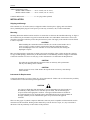
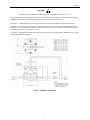
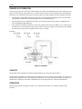
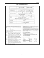
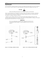
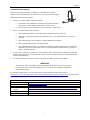
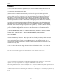
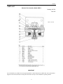
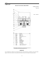
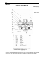
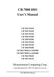
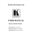
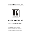
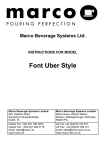
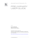
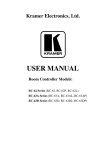
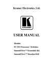
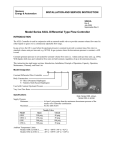
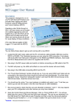
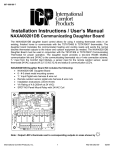
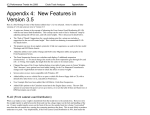
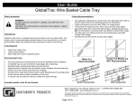
Siemens
Energy & Automation
INSTALLATION AND SERVICE INSTRUCTION
SD63DL
Rev 9
December 2007
Supersedes Rev 8
Model Series 63DL Differential Type Flow Controller
INTRODUCTION
The 63DL Controller is used in conjunction with an external needle valve to provide constant volume flow rates for
either liquids or gases over a continuously adjustable flow range.
In gas service, the 63D is used when the downstream pressure is constant to provide a constant mass flow rate (i.e.
standard volume units per time unit; e.g. SCFM). In gas systems where the upstream pressure is constant, a 63U is
used.
Constant downstream pressure is not needed for constant volume flow rates (i.e. volume units per time unit; e.g.
CFM). Since liquids are incompressible, if the volume is held constant, then the mass is constant.
This instruction has eight major sections: Introduction, Installation, Principle of Operation, Capacity, Operation,
Maintenance, Warranty, and Parts List.
Model Designation
63
B
D
L
Constant Differential Flow Controller
Body Construction
B – Brass (Neoprene Diaphragm)
S – Stainless Steel (Kynar Diaphragm)
Used with Constant Downstream Pressure
Options
L – Very Low Flow Rates
3A – With Rotameter Piped Assembly (Scale: 0.25 to 2.5 SCFH gas)
4A – With Rotameter Piped Assembly (Scale: 18-180 cc/min water)
Specifications
Supply Pressure
Minimum................................. At least 5 psig greater than the maximum downstream pressure of the
needle valve-controller combination
Maximum ................................ See the table below
Needle Valve
Model
63BD
63BD-L
63SD
63SD-L
63BD3A
63BD4A
Open
250 psig
250 psig
500 psig
500 psig
150 psig
150 psig
Closed
100 psig
100 psig
100 psig
100 psig
100 psig
100 psig
SD63DL
Ambient Temperature Limits
Models 63BD & 63BD-L ........ -40° to +180°F (-40° to +82°C)
Models 63SD & 63SD-L......... -40° to +250°F (-40° to +120°C)
Controller Differential ........................... 3.1 ±0.5 psig (others optional)
INSTALLATION
Shipping and Storage
If the controller is to be stocked, stored, or shipped to another location prior to piping, make sure that the
factory installed plastic plugs are in the ports to prevent entry of moisture, dirt, or other contaminants.
Mounting
Mounting dimensions and the locations and sizes of connections are shown on the installation drawing; see Figure 1.
The controller may be mounted in any position. Install the needle valve and feedback connections as close to the
controller as possible to minimize pressure drop between these points. The supply to the controller must be filtered
to remove any solids.
CAUTION
When installing the constant downstream controller, be sure the external needle valve is
open; see Figure 1. Failure to do this could result in applying a differential pressure
across the diaphragm of the flow controller in excess of its rate limit, thus causing the
diaphragm to rupture.
Blow out all piping before connections are made to prevent the possibility of dirt or chips entering the controller.
Use pipe sealant sparingly, and then only on the male threads. A non-hardening sealant is strongly recommended.
Connect the controller to a source of clean, dry, oil-free instrument air. See Instrument Air Requirements.
CAUTION
Exceeding the specified ambient temperature limits can adversely affect performance
and may cause damage to the controller.
CAUTION
Supply pressure in excess of that stated in the Specifications section may cause damage
to the controller.
Instrument Air Requirements
Connect the instrument to a source of clean, dry, oil-free instrument air. Failure to do so will increase the possibility
of a malfunction or a deviation from specified performance.
CAUTION
Use of process fluids other than instrument air is not recommended. No claim is made as to
the suitability of this product for use with other process fluids, such as hazardous gases,
except as listed on the appropriate certificate. Non-approved instruments are suitable for
use with instrument air only. Optional features and modifications such as tapped exhaust do
not imply suitability for use with hazardous gases except as listed on the approval
certificate.
There are many types of synthetic compressor lubricants. Some may not be compatible with the materials used in
construction of the instrument. Wetting of these materials by such an oil mist or vapor, etc., may cause them to
deteriorate. This may ultimately result in failure of the positioner.
2
SD63DL
CAUTION
Synthetic compressor lubricants in the air stream at the instrument may cause it to fail.
The requirements for a quality instrument air supply can be found in the Instrument Society of America's "Quality
Standard for Instrument Air" (ISA-S7.3). Basically, this standard calls for the following:
Particle Size — Maximum particle size in the air stream at the instrument should be no larger than 3 microns.
Dew Point — The dew point, at line pressure, should be at least 10°C (18°F) below the minimum temperature to
which any part of the instrument air system is exposed at any season of the year. Under no circumstances should the
dew point, at line pressure, exceed 2°C (35.6°F).
Oil Content — Maximum total oil or hydrocarbon content, exclusive of non-condensable, should not exceed 1 ppm
under normal operating conditions.
Figure 1 Installation Dimensions
3
SD63DL
PRINCIPLE OF OPERATION
If the pressure drop across a restriction is held constant, the volume flow through the restriction is constant; refer to
Figure 2 on the next page. The needle valve (a variable restriction) can be set to an opening which will produce the
desired flow rate. The pressure drop (∆P) across the needle valve is held constant by the flow controller as follows:
1.
The differential spring and downstream pressure (P2) force the diaphragm and plunger down. The differential
spring produces a downforce equal to that produced by a constant pressure (K).
2.
The output pressure (P1) is applied to the needle valve and to the bottom of the controller’s diaphragm and
forces the diaphragm and plunger up.
3.
The controller is in balance when the force due to P1 equals the forces due to P2 and K (i.e. P1= P2+K; P2=P1K; and K=P1-P2). Since the pressure drop (∆P) across the needle valve equals P1-P2 and since P1-P2 equals K,
then the pressure drop (∆P) must equal K; therefore flow is constant.
Examples:
P1 = P2+K
= 15+3
= 18 psig
P2 = P1-K
= 18-3
= 15 psig
K = P1-P2
= 18-15
= 3 psig
Figure 2 Schematic
CAPACITY
The formulas for the calculation of maximum and minimum flow rated can be found in Table 1.
The minimum controllable flow will depend on the leakage past the valve plunger in the controller. It is, therefore, a
function of the cleanliness of the valve and pressure drop across it as well as any inherent leakage. In general, for a
standard flow controller, the maximum controllable flow will be approximately 1/100 of the maximum flow.
OPERATION
With the supply turned on, adjust the needle valve to obtain the desired flow rate, within the capacity of the
controller.
4
SD63DL
Table 1 Flow Capacity Formulas
5
SD63DL
MAINTENANCE
The only maintenance normally required is to keep the valve plunger and external needle valve clean. Any change in
the rate of flow for a given needle valve setting will probably be caused by partial clogging of the needle valve.
CAUTION
Before disassembling the instrument, turn off supply air pressure to the instrument.
Failure to obtain minimum flows will probable be caused by solids on the controller valve plunger. In the Model
Series 63D, this may be removed for cleaning by unscrewing the retaining nut in the base of the controller and
removing the valve plunger and spring (see Figure 3).
A 63DL has a valve assembly which can be removed by first unscrewing the retaining nut in the base of the
controller and then unscrewing the valve assembly. This assembly can be disassembled for cleaning by removing the
snap ring fastened in the bottom of the valve port (see Figure 4).
IMPORTANT
The valve port and plunger are paired through a lapping process and must not be
interchanged with other assemblies. Clean by washing in solvent. Do not use any
abrasives.
Figure 3 Valve Plunger, Model Series 63D
Figure 4 Valve Assembly, Model Series 63DL
6
SD63DL
Customer/Product Support
This section provides the Internet site addresses, e-mail addresses, telephone
numbers, and related information for customers to access Siemens product support.
When contacting Siemens for support:
•
•
Please have complete product information at hand:
•
For hardware, this information is provided on the product nameplate
(part number or model number, serial number, and/or version).
•
For most software, this information is given in the Help > About screen.
If there is a problem with product operation:
•
Is the problem intermittent or repeatable? What symptoms have been observed?
•
What steps, configuration changes, loop modifications, etc. were performed before the problem
occurred?
•
What status messages, error messages, or LED indications are displayed?
•
What troubleshooting steps have been performed?
•
Is the installation environment (e.g. temperature, humidity) within the product’s specified operating
parameters? For software, does the PC meet or exceed the minimum requirements (e.g. processor,
memory, operating system)?
•
A copy of the product Service Instruction, User’s Manual or other technical literature should be at hand. The
Siemens public Internet site (see the table) has current revisions of technical literature, in Portable Document
Format, for downloading.
•
To send an instrument to Siemens for repair, request a Return Material Authorization (RMA).
IMPORTANT
An instrument must be thoroughly cleaned (decontaminated) to remove any process materials,
hazardous materials, or blood born pathogens prior to return for repair. Read and complete the
Siemens RMA form(s).
For customer/product support, visit the Siemens Process Instrumentation product support page at
http://www2.sea.siemens.com/Products/Process-Instrumentation/Support/Customer-Support.htm. Select the desired
type of support (e.g. application, product selection, sales, technical – see below).
Technical Support
Telephone
E-mail
Hours of Operation
Technical Publications
in PDF
Public Internet Site
Repair Service
1 800 333 7421
[email protected]
8 a.m. to 4:45 p.m. eastern time, Monday through Friday (except holidays)
http://www2.sea.siemens.com/Products/Process-Instrumentation/Support/PI-UserManuals.htm then click the product line (e.g. Control Solutions)
http://www2.sea.siemens.com/Products/Process-Instrumentation
1 215 646 7400 extension 3187
7
SD63DL
WARRANTY
(a) Seller warrants that on the date of shipment the goods are of the kind and quality described herein and
are free of non-conformities in workmanship and material. This warranty does not apply to goods
delivered by Seller but manufactured by others.
(b) Buyer's exclusive remedy for a nonconformity in any item of the goods shall be the repair or the
replacement (at Seller's option) of the item and any affected part of the goods. Seller’s obligation to repair
or replace shall be in effect for a period of one (1) year from initial operation of the goods but not more
than eighteen (18) months from Seller’s shipment of the goods, provided Buyer has sent written notice
within that period of time to Seller that the goods do not conform to the above warranty. Repaired and
replacement parts shall be warranted for the remainder of the original period of notification set forth above,
but in no event less than 12 months from repair or replacement. At its expense, Buyer shall remove and
ship to Seller any such nonconforming items and shall reinstall the repaired or replaced parts. Buyer shall
grant Seller access to the goods at all reasonable times in order for Seller to determine any nonconformity
in the goods. Seller shall have the right of disposal of items replaced by it. If Seller is unable or unwilling
to repair or replace, or if repair or replacement does not remedy the nonconformity, Seller and Buyer shall
negotiate an equitable adjustment in the contract price, which may include a full refund of the contract
price for the nonconforming goods.
(c) SELLER HEREBY DISCLAIMS ALL OTHER WARRANTIES, EXPRESS OR IMPLIED, EXCEPT
THAT OF TITLE. SPECIFICALLY, IT DISCLAIMS THE IMPLIED WARRANTIES OF
MERCHANTABILITY, FITNESS FOR A PARTICULAR PURPOSE, COURSE OF DEALING AND
USAGE OF TRADE.
(d) Buyer and successors of Buyer are limited to the remedies specified in this article and shall have no
others for a nonconformity in the goods. Buyer agrees that these remedies provide Buyer and its successors
with a minimum adequate remedy and are their exclusive remedies, whether Buyer's or its successors’
remedies are based on contract, warranty, tort (including negligence), strict liability, indemnity, or any
other legal theory, and whether arising out of warranties, representations, instructions, installations, or nonconformities from any cause.
(e) Note: The above does not apply to any software which may be furnished by Seller. In such cases, the
attached Software License Addendum applies.
Refer to the Customer/Product Support section of this manual for warranty and non-warranty service.
All product designations may be trademarks or product names of Siemens Energy & Automation, Inc. or other supplier
companies whose use by third parties for their own purposes could violate the rights of the owners.
Siemens Energy & Automation, Inc. assumes no liability for errors or omissions in this document or for the application and use
of information in this document. The information herein is subject to change without notice.
Procedures in this document have been reviewed for compliance with applicable approval agency requirements and are
considered sound practice. Neither Siemens Energy & Automation, Inc. nor these agencies are responsible for repairs made by
the user.
8
SD63DL
PARTS LIST
Siemens Flow Controller, Model 63BD-L
Drawing 10671PL
Rev 5/87
B/M - 10671S8
IMPORTANT
Service Parts Kits are available for servicing the instrument. Contact Siemens for available kits; refer to the Product
Support section of this instruction. Some parts in this Parts List may not be available for separate purchase.
9
SD63DL
PARTS LIST
Siemens Flow Controller, Model 63SD-L
Drawing 12047PL
Rev 5/87
B/M – 12047S12
IMPORTANT
Service Parts Kits are available for servicing the instrument. Contact Siemens for available kits; refer to the Product
Support section of this instruction. Some parts in this Parts List may not be available for separate purchase.
10
SD63DL
PARTS LIST
Siemens Flow Controller, Model 63BD
Drawing 2881PL
Rev 5/87
B/M – 2881S15
IMPORTANT
Service Parts Kits are available for servicing the instrument. Contact Siemens for available kits; refer to the Product
Support section of this instruction. Some parts in this Parts List may not be available for separate purchase.
11
SD63DL
PARTS LIST
Siemens Flow Controller, Model 63SD
Drawing 12042PL
Rev 5/87
B/M – 12042S11
IMPORTANT
Service Parts Kits are available for servicing the instrument. Contact Siemens for available kits; refer to the Product
Support section of this instruction. Some parts in this Parts List may not be available for separate purchase.
12