1
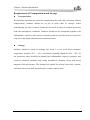
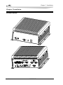
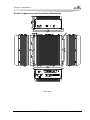
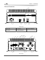
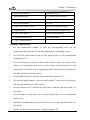
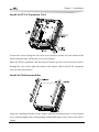
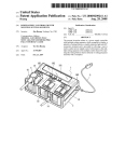
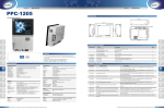
MEC-5007 微型低功耗无风扇嵌入式整机 Mini-type Low Power Fanless Embedded Box PC Version: C00 Copyright Notice Information offered in this manual is believed to be correct at the time of printing, and is subject to change without prior notice in order to improve reliability, design and function and does not represent a commitment on the part of the manufacturer. In no event will the manufacturer be liable for direct, indirect, special, incidental, or consequential damages arising out of improper installation and/or use, or inability to use the product or documentation. This user manual is protected by copyright. No part of this manual may be reproduced, stored in any retrieval system, or transmitted, in any form or by any means, mechanical, electronic, photocopied, recorded or otherwise, without the prior written permission from the manufacturer. Trademarks EVOC is a registered trademark of EVOC Intelligent Technology Co., Ltd. Other product names mentioned herein are used for identification purposes only and may be trademark and/or registered trademarks of their respective companies. Please visit our website: http://www.evoc.com for more information, Or send to the Technical [email protected] for consultation. Support Mailbox [email protected] or Safety Instructions 1. Please read this manual carefully before using the product; 2. Before inserting, removing or re-configuring motherboards or expansion cards, first disconnect the computer and peripherals from their power sources to prevent electric shock to human bodies or damage to the product; 3. Before moving the product, please unplug the AC cable from the power socket; 4. When inserting or removing boards, please firstly unplug the AC power cable; 5. Before connecting or disconnecting any signal cable, make sure all power cables are unplugged in advance; 6. After turning off the computer, wait at least 30 seconds before turning it back on; 7. All the operations such as upgrade, remove or installation shall be implemented on the ESD worktable, because some exactitude components are sensitive to electrostatic discharge (ESD). 8. If there's no ESD worktable, please take the following measures to prevent damage from electrostatic discharge (ESD): a) Wear a antistatic wrist strap and connect it with the metal part of the corresponding product; b) Always touch the metal enclosure or frame before touching any components; c) Keep part of your body in contact with the metal enclosure to discharge the static while handling components; d) Avoid unnecessary movement; e) Hold the components (especially the boards) by the edges; f) Place the components on a grounded, static-free operating platform. Use a conductive foam pad if available (not the component wrapper). g) 9. Do not let the components slide on the operating platform. Use cross-head screwdriver to operate. A magnetic screwdriver is recommended (Magnet helps to prevent screws from remaining in the enclosure). Do not leave any tools or accessories inside the enclosure; 10. Ensure abundant cooling and ventilation. 11. Non-professional personnel are not allowed to open the enclosure. C o n t e n t s Chapter 1 Product Introduction.....................................................................................1 Overview ......................................................................................................................1 Main Function...............................................................................................................1 Main Performance ........................................................................................................3 Mounting Mode ............................................................................................................4 Requirements of Transportation and Storage ................................................................5 Chapter 2 Installation....................................................................................................6 Product Outline.............................................................................................................6 Product Appearance and Installation Dimensions.........................................................7 External Connectors......................................................................................................8 Overall Assembly Drawing...........................................................................................9 Install the Hard Disk ................................................................................................... 11 Install the PCI-E Expansion Card ...............................................................................12 Install the Wall-mounted Bar ......................................................................................12 Chapter 3 Install the Drivers.......................................................................................13 Chapter 1 Product Introduction Chapter 1 Product Introduction Overview MEC-5007 is a high performance low power fanless embedded box PC. The product features al-alloy chassis, small form factor, compact and rugged structure, as well as fanless design. The PC dissipates heat from the shell, and provides excellent dust-proof, heat dissipation and anti-vibration performance. The product can be used in harsh environments with heavy contamination, dust and serious EMI, etc. MEC-5007 contains the latest Intel® QM57 high performance processor solution, supporting Intel® AMT6.0 technology. The prominent feature of the AMT technology is to support the maintenance personnel to maintain and control the remote console. The PC provides small size, complete function and strong environment adaptability, and targets high-end customers. It is mainly applied in the media video fields such as multi-media advertising players, flight information display at airport and video surveillance for intelligent transportation, etc. Main Function Microprocessor Supports the Mobile processor of the Intel® rPGA988 package: Intel® CoreTM i7 600 series, Intel® CoreTM i5 500 and 400 series, Intel® CoreTM i3 300 series and Intel® Celeron® Processor P4500(AMT6.0 is not supported by this type of the CPU); the PC supports Intel® CoreTM i7 620M or i5 520M in standard configuration. Chipset Mobile Intel® QM57 Express Chipset Memory Provides two 204Pin DDR3 SODIMM memory slots, supporting Un-buffered Non-ECC memory. The maximum memory capacity for a single slot is up to 4GB while that supported by the board is up to 8GB with the supported memory frequency: MEC-5007 -1- Chapter 1 Product Introduction 800/1066MHz. The PC provides a single 2G memory bank as standard configuration. Network Function Provides two 10/100/1000Mbps LAN ports; LAN1 supports Wake-on-LAN, LAN PXE booting and AMT6.0 functions. Display Function Adopts Intel® Arrandale CPU built-in integrated graphic controller display chip; Supports independent dual-display CRT+HDMI and hot swap function, both of which are synchronous output; The maximum resolution and fresh frequency supported by VGA is up to 2048x1536@75Hz while that supported by HDMI is up to 1920x1200@60Hz. Audio Function Adopts ALC888 HDA sound effect chip, supporting MIC-in/Line-in/Line-out functions. On-board IO Four RS-232 serial ports, COM1 supports RS-232/RS-422/RS-485 mode and Modem wake-up function; Four USB2.0 ports (two are front-accessible while the other two are at the rear); One VGA connector; One HDMI connector; Two 10/100/1000Mbps LAN ports; A set of audio connectors (MIC-in/Line-in/Line-out); One DC-in connector. -2- MEC-5007 Chapter 1 Product Introduction Storage Device Provides one 2.5″ 250G hard disk as standard configuration; Power Feature The PC provides one built-in DC-DC wide-voltage input power module as well as AC-DC adapter in standard configuration. ① PC DC wide voltage input feature. Input Voltage/Frequency: 9 ~ 36V DC. ② AC-DC adapter feature: Power Type: appropriate adapter; Input Voltage/Frequency: 100 ~ 240V AC 50Hz/60Hz; Total Power: 90W(Max); Output Voltage/Current: [email protected] (Max), +5%/-5%. Expansion Bus Expand one PCIe card with 106.7mm in height and 167.7mm in length, complying with PCIE2.0 standard. Power Consumption of the PC Power Consumption: 21.1W (Standby) Power Consumption: 43.4W (100% operate 3D) Main Performance Mechanical Dimensions, Weight and Environment Dimensions: 290mm (L) x 242mm (W) x 112.5mm (H); Net Weight: 7.2Kg; Operating Environment: Temperature: 0°C ~ 45°C; Humidity: 5% ~ 90% (non-condensing); MEC-5007 -3- Chapter 1 Product Introduction Storage Environment: Temperature: -30°C ~ 65°C; Humidity: 5% ~ 90% (non-condensing); EMC GB9254-1998 Radiation susceptibility class A, Conducted disturbance class A; GB/T 17626.2.2006 Electrostatic discharge, level 2; GB/T 17626.3-2006 Burst immunity, level 2; GB/T 17626.5-2008 Surge (Impact) immunity, level 2; GB/T 17626.6-2008 Conducted susceptibility, level 2. Reliability MTBF≥50000h; MTTR≤0.5h. Safety Meets the basic requirements of GB4943. Mechanical and Environment Adaptability Anti-vibration: 5-19Hz/1.0mm amplitude; 19-200Hz/1.0g acceleration; Anti-shock: 15g acceleration, 11ms duration. Mounting Mode □19″ Rack Mount ■Wall Mount □Desktop □Embedded Panel □VESA Standard Supporting Arm □Others___________ -4- MEC-5007 □Portable Chapter 1 Product Introduction Requirements of Transportation and Storage Transportation Well-packaged products are suited for transportation by truck, ship, and plane. During transportation, products should not be put in open cabin or carriage. When transshipping en route, products should not be stored in open air without protection from the atmospheric conditions. Products should not be transported together with inflammable, explosive and corrosive substances and are not allowed to be exposed to rain, snow and liquid substances and mechanical force. Storage Products should be stored in package box when it is not used. And warehouse temperature should be 0°C ~ 40°C, and relative humidity should be 20% ~ 85%. In the warehouse, there should be no harmful gas, inflammable, explosive products, and corrosive chemical products, and strong mechanical vibration, shock and strong magnetic field interference. The package box should be at least 10cm above ground, and 50cm away from wall, thermal source, window and air inlet. MEC-5007 -5- Chapter 2 Installation Chapter 2 Installation Product Outline -6- MEC-5007 Chapter 2 Installation Product Appearance and Installation Dimensions Unit: mm MEC-5007 -7- Chapter 2 Installation External Connectors 5 1 2 3 4 Front Panel 1. DC-IN 2. USB 1/2 3. Power Indicator 4. Switch 5. HDD Indicator 5 6 7 1 2 3 4 8 13 14 Rear Panel -8- MEC-5007 10 9 11 12 Chapter 2 Installation 1. HDMI 2. LAN2 3. LAN1 4. VGA 5. Line-in 6. Mic-in 7. Line-out 8. COM1 9. COM2 10. USB 3/4 11. COM3 12. COM4 13. PCI-E Expansion Card 14. Grounding Screw Overall Assembly Drawing 8 6 7 9 12 13 5 14 15 4 10 17 11 16 2 1 MEC-5007 3 -9- Chapter 2 Installation 1. Front Panel Module 2. Bottom Cover 3. Mounting Bracket 4. Left Panel of the Chassis 5. Fixing Bar of the Upper Cover 6. I/O Bracket 7. Rear Panel Module 8. Cover 9. Right Panel of the Chassis 10. Power Supporting Board 11. Power Board 12. Motherboard Fixing Bracket 13. FPC Patch Board 14. PCI-E Patch Board 15. Motherboard Module 16. HDD Module 17. CPU Thermal Block Assembly Instructions 1. Fix the motherboard module 15 with the corresponding rivets on the motherboard fixing bracket 12 and then tighten the corresponding screws; 2. Fix the PCI-E patch board 14 and the FPC patch board 13 on the motherboard fixing bracket 12; 3. Fix the foresaid parts on the left side board 4 and the right side board 9 of the chassis via countersunk head screws (Note: before operation please fix the power board 11 with the power supporting board 10 and then fix the module on the right side board 9 of the chassis); 4. Fix the HDD module 16 with the motherboard fixing bracket 12; 5. Fix the front panel module 1 and rear panel module 7 with the left side board 4 and the right side board 9 of the chassis; 6. Fix the bottom cover 2 with the left side board 4 and the right side board 9 of the chassis; 7. Fix the fixing bar of the upper cover on both sides of the cover via countersunk head screws; 8. Install the foresaid module on the left side board 4 and the right side board 9 of the chassis; 9. Finally, fix the mounting bracket 3 to form a complete PC. - 10 MEC-5007 Chapter 2 Installation Install the Hard Disk Loosen the screws on the HDD module tray 2 and the HDD module tray 1 via crosshead screwdriver and take off the HDD module. Install the 2.5″ hard disk (Users may install the HDD according to their requirement) into the HDD fixing bracket; make sure the screw holes on both sides of the hard disk are in alignment with the mounting holes on the HDD fixing bracket; fix via pan head screws and connect the cables. Finally, fix the removed module back on the HDD module tray 2 and tighten the corresponding screws. MEC-5007 - 11 - Chapter 2 Installation Install the PCI-E Expansion Card Loosen the screws fixing the slot cover screw bracket and the left side board of the chassis and then take off the slot cover screw bracket. Insert the PCI-E expansion card into the I/O bracket; get the cross head screw driver through the vias on the right side board of the chassis and fix the PCI-E expansion card via truss head screws. Install the Wall-mounted Bar Align the mounting bracket of the chassis with the mounting holes on the bottom cover and then tighten the corresponding countersunk head screws (refer to the above figure). - 12 - MEC-5007 Chapter 3 Install the Drivers Chapter 3 Install the Drivers Regarding the installation of the driver program, please refer to the CD that accompanies the PC. MEC-5007 - 13 -