1
To our customers,
Old Company Name in Catalogs and Other Documents
On April 1st, 2010, NEC Electronics Corporation merged with Renesas Technology
Corporation, and Renesas Electronics Corporation took over all the business of both
companies. Therefore, although the old company name remains in this document, it is a valid
Renesas Electronics document. We appreciate your understanding.
Renesas Electronics website: http://www.renesas.com
April 1st, 2010
Renesas Electronics Corporation
Issued by: Renesas Electronics Corporation (http://www.renesas.com)
Send any inquiries to http://www.renesas.com/inquiry.
Note that the following URLs in this document are not available:
http://www.necel.com/
http://www2.renesas.com/
Please refer to the following instead:
Development Tools | http://www.renesas.com/tools
Download | http://www.renesas.com/tool_download
For any inquiries or feedback, please contact your region.
http://www.renesas.com/inquiry
Notice
1.
2.
3.
4.
5.
6.
7.
All information included in this document is current as of the date this document is issued. Such information, however, is
subject to change without any prior notice. Before purchasing or using any Renesas Electronics products listed herein, please
confirm the latest product information with a Renesas Electronics sales office. Also, please pay regular and careful attention to
additional and different information to be disclosed by Renesas Electronics such as that disclosed through our website.
Renesas Electronics does not assume any liability for infringement of patents, copyrights, or other intellectual property rights
of third parties by or arising from the use of Renesas Electronics products or technical information described in this document.
No license, express, implied or otherwise, is granted hereby under any patents, copyrights or other intellectual property rights
of Renesas Electronics or others.
You should not alter, modify, copy, or otherwise misappropriate any Renesas Electronics product, whether in whole or in part.
Descriptions of circuits, software and other related information in this document are provided only to illustrate the operation of
semiconductor products and application examples. You are fully responsible for the incorporation of these circuits, software,
and information in the design of your equipment. Renesas Electronics assumes no responsibility for any losses incurred by
you or third parties arising from the use of these circuits, software, or information.
When exporting the products or technology described in this document, you should comply with the applicable export control
laws and regulations and follow the procedures required by such laws and regulations. You should not use Renesas
Electronics products or the technology described in this document for any purpose relating to military applications or use by
the military, including but not limited to the development of weapons of mass destruction. Renesas Electronics products and
technology may not be used for or incorporated into any products or systems whose manufacture, use, or sale is prohibited
under any applicable domestic or foreign laws or regulations.
Renesas Electronics has used reasonable care in preparing the information included in this document, but Renesas Electronics
does not warrant that such information is error free. Renesas Electronics assumes no liability whatsoever for any damages
incurred by you resulting from errors in or omissions from the information included herein.
Renesas Electronics products are classified according to the following three quality grades: “Standard”, “High Quality”, and
“Specific”. The recommended applications for each Renesas Electronics product depends on the product’s quality grade, as
indicated below. You must check the quality grade of each Renesas Electronics product before using it in a particular
application. You may not use any Renesas Electronics product for any application categorized as “Specific” without the prior
written consent of Renesas Electronics. Further, you may not use any Renesas Electronics product for any application for
which it is not intended without the prior written consent of Renesas Electronics. Renesas Electronics shall not be in any way
liable for any damages or losses incurred by you or third parties arising from the use of any Renesas Electronics product for an
application categorized as “Specific” or for which the product is not intended where you have failed to obtain the prior written
consent of Renesas Electronics. The quality grade of each Renesas Electronics product is “Standard” unless otherwise
expressly specified in a Renesas Electronics data sheets or data books, etc.
“Standard”:
8.
9.
10.
11.
12.
Computers; office equipment; communications equipment; test and measurement equipment; audio and visual
equipment; home electronic appliances; machine tools; personal electronic equipment; and industrial robots.
“High Quality”: Transportation equipment (automobiles, trains, ships, etc.); traffic control systems; anti-disaster systems; anticrime systems; safety equipment; and medical equipment not specifically designed for life support.
“Specific”:
Aircraft; aerospace equipment; submersible repeaters; nuclear reactor control systems; medical equipment or
systems for life support (e.g. artificial life support devices or systems), surgical implantations, or healthcare
intervention (e.g. excision, etc.), and any other applications or purposes that pose a direct threat to human life.
You should use the Renesas Electronics products described in this document within the range specified by Renesas Electronics,
especially with respect to the maximum rating, operating supply voltage range, movement power voltage range, heat radiation
characteristics, installation and other product characteristics. Renesas Electronics shall have no liability for malfunctions or
damages arising out of the use of Renesas Electronics products beyond such specified ranges.
Although Renesas Electronics endeavors to improve the quality and reliability of its products, semiconductor products have
specific characteristics such as the occurrence of failure at a certain rate and malfunctions under certain use conditions. Further,
Renesas Electronics products are not subject to radiation resistance design. Please be sure to implement safety measures to
guard them against the possibility of physical injury, and injury or damage caused by fire in the event of the failure of a
Renesas Electronics product, such as safety design for hardware and software including but not limited to redundancy, fire
control and malfunction prevention, appropriate treatment for aging degradation or any other appropriate measures. Because
the evaluation of microcomputer software alone is very difficult, please evaluate the safety of the final products or system
manufactured by you.
Please contact a Renesas Electronics sales office for details as to environmental matters such as the environmental
compatibility of each Renesas Electronics product. Please use Renesas Electronics products in compliance with all applicable
laws and regulations that regulate the inclusion or use of controlled substances, including without limitation, the EU RoHS
Directive. Renesas Electronics assumes no liability for damages or losses occurring as a result of your noncompliance with
applicable laws and regulations.
This document may not be reproduced or duplicated, in any form, in whole or in part, without prior written consent of Renesas
Electronics.
Please contact a Renesas Electronics sales office if you have any questions regarding the information contained in this
document or Renesas Electronics products, or if you have any other inquiries.
(Note 1) “Renesas Electronics” as used in this document means Renesas Electronics Corporation and also includes its majorityowned subsidiaries.
(Note 2) “Renesas Electronics product(s)” means any product developed or manufactured by or for Renesas Electronics.
User’s Manual
CA850 Ver. 3.20
C Compiler Package
Operation
Target Device
V850 Series
Document No. U18512EJ1V0UM00 (1st edition)
Date Published May 2007 CP(K)
© NEC Electronics Corporation 2007
Printed in Japan
[MEMO]
2
User’s Manual U18512EJ1V0UM
Windows is either a registered trademark or a trademark of Microsoft Corporation in the United States
and/or other countries.
User’s Manual U18512EJ1V0UM
3
• The information in this document is current as of May, 2007. The information is subject to change
without notice. For actual design-in, refer to the latest publications of NEC Electronics data sheets or
data books, etc., for the most up-to-date specifications of NEC Electronics products. Not all
products and/or types are available in every country. Please check with an NEC Electronics sales
representative for availability and additional information.
• No part of this document may be copied or reproduced in any form or by any means without the prior
written consent of NEC Electronics. NEC Electronics assumes no responsibility for any errors that may
appear in this document.
• NEC Electronics does not assume any liability for infringement of patents, copyrights or other intellectual
property rights of third parties by or arising from the use of NEC Electronics products listed in this document
or any other liability arising from the use of such products. No license, express, implied or otherwise, is
granted under any patents, copyrights or other intellectual property rights of NEC Electronics or others.
• Descriptions of circuits, software and other related information in this document are provided for illustrative
purposes in semiconductor product operation and application examples. The incorporation of these
circuits, software and information in the design of a customer's equipment shall be done under the full
responsibility of the customer. NEC Electronics assumes no responsibility for any losses incurred by
customers or third parties arising from the use of these circuits, software and information.
• While NEC Electronics endeavors to enhance the quality, reliability and safety of NEC Electronics products,
customers agree and acknowledge that the possibility of defects thereof cannot be eliminated entirely. To
minimize risks of damage to property or injury (including death) to persons arising from defects in NEC
Electronics products, customers must incorporate sufficient safety measures in their design, such as
redundancy, fire-containment and anti-failure features.
• NEC Electronics products are classified into the following three quality grades: "Standard", "Special" and
"Specific".
The "Specific" quality grade applies only to NEC Electronics products developed based on a customerdesignated "quality assurance program" for a specific application. The recommended applications of an NEC
Electronics product depend on its quality grade, as indicated below. Customers must check the quality grade of
each NEC Electronics product before using it in a particular application.
"Standard": Computers, office equipment, communications equipment, test and measurement equipment, audio
and visual equipment, home electronic appliances, machine tools, personal electronic equipment
and industrial robots.
"Special": Transportation equipment (automobiles, trains, ships, etc.), traffic control systems, anti-disaster
systems, anti-crime systems, safety equipment and medical equipment (not specifically designed
for life support).
"Specific": Aircraft, aerospace equipment, submersible repeaters, nuclear reactor control systems, life
support systems and medical equipment for life support, etc.
The quality grade of NEC Electronics products is "Standard" unless otherwise expressly specified in NEC
Electronics data sheets or data books, etc. If customers wish to use NEC Electronics products in applications
not intended by NEC Electronics, they must contact an NEC Electronics sales representative in advance to
determine NEC Electronics' willingness to support a given application.
(Note)
(1) "NEC Electronics" as used in this statement means NEC Electronics Corporation and also includes its
majority-owned subsidiaries.
(2) "NEC Electronics products" means any product developed or manufactured by or for NEC Electronics (as
defined above).
M8E 02. 11-1
4
User’s Manual U18512EJ1V0UM
[MEMO]
User’s Manual U18512EJ1V0UM
5
INTRODUCTION
Target Devices
The CA850 is a C compiler package used to create object codes for NEC
Electronics’s V850 Series of RISC microcontrollers.
This manual explains the features and functions of the CA850 C Compiler Package.
Readers
This manual is intended for user engineers who wish to develop application systems
using the V850 Series C Compiler Package.
Purpose
This manual explains how to operate each command, such as the C compiler and
assembler included in each package on WindowsTM.
PM+ (Windows version only) is provided with this C compiler package. However, for
how to operate PM+ as an integrated development environment, refer to the PM+
user’s manual.
For the Windows operations, refer to the function guides provided with the Windows
OS.
Organization
This manual is organized into the following sections.
• Overview of the CA850
• Using the CA850 from the command line
• Using the CA850 from Project Manager
• Command functions, options, and output messages
Commands Included in This Package
C compiler (ca850)
Assembler (as850)
Linker (ld850)
ROMization processor (romp850)
Hexadecimal converter (hx850)
Archiver (ar850)
Section file generator (sf850)
Dump command (dump850)
Disassembler (dis850)
Cross reference tool (cxref)
Memory layout visualization tool (rammap)
Stack estimation tool (stk850)
How to Read This Manual • The name of each program in the C compiler package is referred to as follows in
this manual.
C compiler package → CA850
Assembler → as850
C compiler → ca850
6
User’s Manual U18512EJ1V0UM
Related Documents
Read this manual together with the following documents.
The related documents indicated in this publication may include preliminary
versions. However, preliminary versions are not marked as such.
Documents related to development tools (user’s manuals)
Document Name
CA850 Ver. 3.20 C Compiler Package
Document No.
Operation
This manual
C Language
U18513E
Assembly Language
U18514E
Link Directives
U18515E
U18416E
PM+ Ver. 6.30 Project Manager
ID850 Ver. 3.00 Integrated Debugger
Operation
U17358E
ID850NW Ver. 3.10 Integrated Debugger
Operation
U17369E
ID850QB Ver. 3.20 Integrated Debugger
Operation
U17964E
SM+ System Simulator
Operation
U17246E
User Open Interface
U18212E
SM850 Ver. 2.50 System Simulator
Operation
U16218E
SM850 Ver. 2.00 or Later System Simulator
External Part User Open Interface Specifications
U14873E
RX850 Ver. 3.20 or Later Real-Time OS
Basics
U13430E
Installation
U17419E
Technical
U13431E
RX850 Pro Ver. 3.21 Real-Time OS
RX850V4 Ver. 4.22 Real-Time OS
Task Debugger
U17420E
Basics
U18165E
Internal Structure
U18164E
Task Debugger
U17422E
Functionalities
U16643E
Internal Structure
U16644E
Task Debugger
U16811E
AZ850 Ver. 3.30 System Performance Analyzer
U17423E
AZ850V4 Ver. 4.10 System Performance Analyzer
U17093E
TW850 Ver. 2.00 Performance Analysis Tuning Tool
U17241E
User’s Manual U18512EJ1V0UM
7
[MEMO]
8
User’s Manual U18512EJ1V0UM
CONTENTS
CHAPTER 1 OVERVIEW ... 20
1.1 Features of Compiler Package ... 20
1.2 Operating Environments ... 22
CHAPTER 2 INSTALLATION ... 23
2.1 Installation ... 23
2.2 Folder Organization ... 24
2.2.1 Folder organization of stack usage tracer ... 25
2.3 Uninstallation ... 26
CHAPTER 3 C COMPILER ... 27
3.1 Flow of Operation ... 27
3.2 Input/Output Files ... 29
3.3 Executable Object ... 30
3.4 Operation Method ... 32
3.4.1 Command input method ... 32
3.4.2 Method using PM+ ... 32
3.5 Types and Features of Options ... 33
3.5.1 Version/help display/operation status ... 34
3.5.2 Output file specification ... 35
3.5.3 Controlling source debugger ... 37
3.5.4 Control of compile driver ... 38
3.5.5 Optimization ... 44
3.5.6 Generation code control ... 49
3.5.7 Library specification ... 59
3.5.8 Warning message control ... 60
3.5.9 Other ... 62
3.5.10 Option to each module ... 64
3.6 Settings Made via PM+ ... 68
3.6.1 [Compiler Common Options] dialog box ... 69
[File] ... 70
[Startup] ... 72
[Link Directive] ... 73
[ROM] ... 74
[Flash] ... 75
[Device] ... 76
[ROM] (library) ... 78
[Flash] (library) ... 79
3.6.2 [Compiler Options] dialog box ... 80
[General] ... 81
[Input File] ... 84
[Preprocessor] ... 86
[C Language] ... 88
[Optimization and Debug Information] ... 90
[Detail of Optimization] ... 92
[External Register] ... 96
[Output File] ... 98
[Output Code] ... 100
[Message] ... 105
[Assembler] ... 107
[Others] ... 109
[Difference] ... 111
User’s Manual U18512EJ1V0UM
9
3.6.3 [Edit Option] dialog box ... 113
3.7 Cautions ... 115
3.7.1 Specifying multiple options ... 115
3.7.2 Command file ... 116
3.7.3 Efficient use of optimization ... 117
3.7.4 Effects of optimization on debugging ... 122
CHAPTER 4 ASSEMBLER ... 124
4.1 Flow of Operation ... 124
4.2 Input/Output Files ... 125
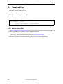
4.3 Operation Method ... 126
4.3.1 Command input method ... 126
4.3.2 Method using PM+ ... 126
4.4 Types and Features of Options ... 127
4.4.1 File ... 128
4.4.2 Option ... 129
4.4.3 Device ... 131
4.4.4 Other ... 133
4.5 Settings Made via PM+ ... 135
4.5.1 [Assembler Options] dialog box ... 136
[Option] ... 137
[Difference] ... 141
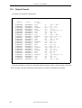
4.6 Assemble List ... 143
4.6.1 Output method ... 143
4.6.2 Output example ... 144
4.7 Cautions ... 146
4.7.1 Magic number ... 146
4.7.2 Options for avoiding CPU faults ... 148
CHAPTER 5 LINKER ... 153
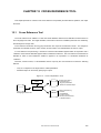
5.1 Flow of Operation ... 153
5.1.1 Link procedure ... 155
5.2 Operation Method ... 157
5.2.1 Command input method ... 157
5.2.2 Method using PM+ ... 157
5.3 Types and Features of Options ... 158
5.3.1 Input file ... 159
5.3.2 Output file ... 160
5.3.3 Library ... 161
5.3.4 Flash ROM ... 162
5.3.5 Device ... 164
5.3.6 Option ... 165
5.3.7 Other ... 168
5.4 Settings Made via PM+ ... 170
5.4.1 [Linker Options] dialog box ... 170
[File] ... 171
[Library] ... 172
[Option] ... 174
[Others] ... 177
5.5 Link Map ... 178
5.5.1 When starting the ld850 from the command line ... 178
5.5.2 When starting from PM+ ... 178
5.5.3 Link map output example ... 178
5.6 Flash Memory/External ROM Relink Function ... 181
5.6.1 Relink function ... 181
5.6.2 Image of relink function ... 182
10
User’s Manual U18512EJ1V0UM
5.6.3 Realizing relink function ... 185
5.7 Supplementary Information ... 194
5.7.1 Using -A option ... 194
5.7.2 Archive files ... 197
5.7.3 Reserved symbols ... 198
5.7.4 May not be allocated to the expected sections ... 199
5.7.5 V850 core and V850Ex core ... 199
5.7.6 V850 core and V850E2 core ... 199
5.7.7 Mathematics library ... 199
5.7.8 main function ... 199
5.7.9 Prologue/epilogue runtime library ... 200
5.7.10 Linking for ROMization ... 201
5.7.11 Programmable peripheral I/O register ... 202
5.7.12 Option byte ... 203
CHAPTER 6 ROMIZATION PROCESSOR ... 204
6.1 Flow of Operation ... 204
6.2 Input/Output Files ... 207
6.3 rompsec Section ... 208
6.3.1 Types of sections to be packed ... 208
6.3.2 Size of rompsec section ... 209
6.3.3 rompsec section and link directive ... 210
6.4 Creating Object for ROMization ... 212
6.4.1 Creating procedure (default) ... 212
6.4.2 Creating procedure (customize) ... 215
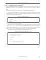
6.5 Copy Functions ... 218
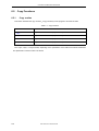
6.5.1 Copy routine ... 218
_rcopy ... 219
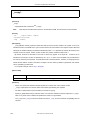
_rcopy1 ... 220
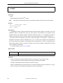
_rcopy2 ... 221
_rcopy4 ... 222
6.5.2 Example ... 223
6.6 Operation Method ... 225
6.6.1 Command input method ... 225
6.6.2 Method using PM+ ... 225
6.7 Types and Features of Options ... 226
6.7.1 File ... 227
6.7.2 Options ... 228
6.7.3 Other ... 230
6.8 Settings Made via PM+ ... 231
6.8.1 [ROM Processor Options] dialog box ... 231
[File] ... 232
[Section] ... 233
[Option] ... 235
[Others] ... 237
CHAPTER 7 HEXADECIMAL CONVERTER ... 238
7.1 Flow of Operation ... 238
7.2 Input/Output Files ... 239
7.3 Operation Method ... 240
7.3.1 Command input method ... 240
7.3.2 Method using PM+ ... 240
7.4 Types and Features of Options ... 241
7.4.1 File ... 242
7.4.2 Format ... 243
7.4.3 Other ... 246
User’s Manual U18512EJ1V0UM
11
7.5 Settings Made via PM+ ... 247
7.5.1 [Hexa Converter Options] dialog box ... 247
[File] ... 248
[Option] ... 249
[Others] ... 252
7.6 Output File Formats ... 253
7.6.1 Intel expanded ... 253
7.6.2 Motorola S type ... 257
7.6.3 Expanded Tek ... 259
CHAPTER 8 ARCHIVER ... 263
8.1 Archiver ... 263
8.2 Operation Method ... 264
8.2.1 Command input method ... 264
8.2.2 Method using PM+ ... 264
8.3 Types and Features of Keys and Options ... 265
8.3.1 Types and features of keys ... 266
8.3.2 Types and features of options ... 268
8.4 Settings Made via PM+ ... 269
8.4.1 [Archiver Options] dialog box ... 269
[Option] ... 270
CHAPTER 9 SECTION FILE GENERATOR ... 272
9.1 Section Files ... 272
9.2 Section File Format ... 275
9.3 Operation Method ... 280
9.3.1 Command input method ... 280
9.3.2 Method using PM+ ... 280
9.3.3 Use from command line ... 281
9.3.4 Use via PM+ ... 282
9.4 Types and Features of Options ... 283
9.4.1 Options ... 284
9.5 Settings Made via PM+ ... 287
9.5.1 [Section File Generator Options] dialog box ... 287
[File] ... 288
[Option] ... 289
[Others] ... 292
CHAPTER 10 DUMP COMMAND ... 293
10.1 Dump Command ... 293
10.2 Operation Method ... 294
10.2.1 Command input method ... 294
10.2.2 Method using PM+ ... 294
10.3 Types and Features of Options ... 295
10.4 Settings Made via PM+ ... 297
10.4.1 [Object Analysis Tool] dialog box ... 297
[Dump] ... 298
10.4.2 [Output Index] dialog box ... 302
10.4.3 [Archive File Options] dialog box ... 303
10.5 Dump List ... 304
10.5.1 Dump list display contents ... 304
10.5.2 Element values and meanings ... 310
CHAPTER 11 DISASSEMBLER ... 313
11.1 Disassembler ... 313
12
User’s Manual U18512EJ1V0UM
11.2 Operation Method ... 314
11.2.1 Command input method ... 314
11.2.2 Method using PM+ ... 314
11.3 Types and Features of Options ... 315
11.4 Settings Made via PM+ ... 317
11.4.1 [Object Analysis Tool] dialog box ... 317
[Disassembler] ... 318
11.5 Cautions ... 321
11.6 Output Format ... 322
CHAPTER 12 CROSS REFERENCE TOOL ... 323
12.1 Cross Reference Tool ... 323
12.2 Input/Output ... 324
12.2.1 Input file ... 324
12.2.2 Output information ... 325
12.3 Operation Method ... 326
12.3.1 Command input method ... 326
12.3.2 Method using PM+ ... 326
12.4 Types and Features of Options ... 327
12.4.1 Common options ... 328
12.4.2 Cross reference ... 331
12.4.3 Tag information ... 332
12.4.4 Call tree ... 333
12.4.5 Function metrics ... 334
12.4.6 Call database ... 335
12.5 Settings Made via PM+ ... 336
12.5.1 [Static performance analyzer] dialog box ... 336
[Cross reference] ... 337
12.5.2 [Cross reference Option] dialog box ... 340
[Common option] ... 341
[Cross reference list] ... 344
[Tag information] ... 345
[Call graph] ... 346
[Function measure] ... 349
[Call database] ... 351
12.6 Output Files ... 353
12.6.1 Cross reference ... 353
12.6.2 Tag information ... 355
12.6.3 Call tree ... 357
12.6.4 Function metrics ... 360
12.6.5 Call database ... 363
CHAPTER 13 MEMORY LAYOUT VISUALIZATION TOOL ... 366
13.1 Memory Layout Visualization Tool ... 366
13.2 Input/Output ... 367
13.2.1 Input file ... 367
13.2.2 Output information ... 367
13.3 Operation Method ... 368
13.3.1 Command input method ... 368
13.3.2 Method using PM+ ... 368
13.4 Types and Features of Options ... 369
13.5 Settings Made via PM+ ... 372
13.5.1 [Static performance analyzer] dialog box ... 372
[RAM map] ... 373
13.5.2 [RAM map option] dialog box ... 375
[Common option] ... 376
User’s Manual U18512EJ1V0UM
13
13.5.3 [Object Analysis Tool] dialog box ... 378
[RAM map] ... 379
13.6 Output Files ... 381
13.6.1 Memory map table ... 381
CHAPTER 14 STACK USAGE TRACER ... 383
14.1 Flow of Operation ... 383
14.2 Input/Output Files ... 384
14.2.1 Input files ... 384
14.2.2 Output file ... 384
14.3 Operation Method ... 385
14.4 Window Reference ... 386
Main window ... 388
[Adjust Stack Size] dialog box ... 392
[Stack Size Unknown / Adjusted Function Lists] dialog box ... 394
[About stk850] dialog box ... 396
14.5 Cautions ... 397
14.5.1 Quantitative limit of the stk850 ... 397
14.6 Output File Formats ... 399
14.6.1 Output result files ... 399
14.6.2 Stack size specification file ... 402
14.6.3 stk system file ... 405
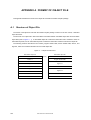
APPENDIX A FORMAT OF OBJECT FILE ... 406
A.1 Structure of Object File ... 406
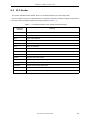
A.2 ELF Header ... 407
A.3 Program Header Table ... 408
A.4 Section Header Table ... 409
A.4.1 Section types ... 410
A.4.2 Constituent elements (link/info) dependent on section type ... 410
A.5 Sections ... 411
A.5.1 Symbol table ... 411
A.5.2 String table ... 412
A.5.3 Reserved sections ... 413
APPENDIX B MESSAGE ... 415
B.1 Output Message ... 415
B.1.1 Message format ... 415
B.1.2 Compiler ... 416
B.1.3 Assembler ... 442
B.1.4 Linker ... 450
B.1.5 ROMization process ... 468
B.1.6 Hexadecimal converter ... 471
B.1.7 Archiver ... 477
B.1.8 Section file generator ... 479
B.1.9 Dump command ... 480
B.1.10 Disassembler ... 481
B.1.11 Cross reference tool ... 482
B.1.12 Memory layout visualization tool ... 484
B.2 Messages from PM+ ... 486
B.2.1 Format of message ... 486
B.2.2 Messages common to compiler ... 486
B.2.3 Compiler ... 487
B.2.4 Assembler ... 488
B.2.5 Linker ... 488
B.2.6 ROMization processor ... 489
14
User’s Manual U18512EJ1V0UM
B.2.7 Hexadecimal converter ... 489
B.2.8 Archiver ... 490
B.2.9 Section file generator ... 490
B.2.10 Cross reference tool and memory layout visualization tool ... 491
B.3 Messages from stk850 ... 493
B.3.1 Message formats ... 493
B.3.2 Messages ... 493
APPENDIX C INDEX ... 498
User’s Manual U18512EJ1V0UM
15
LIST OF FIGURES
Figure No. Title Page
1-1
2-1
2-2
3-1
3-2
3-3
3-4
3-5
3-6
3-7
3-8
3-9
3 - 10
3 - 11
3 - 12
3 - 13
3 - 14
3 - 15
3 - 16
3 - 17
3 - 18
3 - 19
3 - 20
3 - 21
3 - 22
3 - 23
3 - 24
3 - 25
3 - 26
3 - 27
4-1
4-2
4-3
4-4
4-5
4-6
5-1
5-2
5-3
5-4
5-5
5-6
5-7
5-8
5-9
5 - 10
5 - 11
5 - 12
5 - 13
5 - 14
5 - 15
5 - 16
5 - 17
5 - 18
5 - 19
5 - 20
16
Package Configuration ... 21
Folder Organization ... 24
Folder Organization of Stack Usage Tracer ... 25
Operation Flow of ca850 ... 28
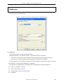
[Compiler Common Options] Dialog Box ([File] Tab) ... 70
Checking Creation of Folder ... 71
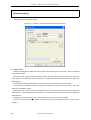
[Compiler Common Options] Dialog Box ([Startup] Tab) ... 72
[Compiler Common Options] Dialog Box ([Link Directive] Tab) ... 73
[Compiler Common Options] Dialog Box ([ROM] Tab) ... 74
[Compiler Common Options] Dialog Box ([Flash] Tab) ... 75
[Compiler Common Options] Dialog Box ([Device] Tab) ... 76
[Compiler Common Options] Dialog Box ([ROM] Tab (library)) ... 78
[Compiler Common Options] Dialog Box ([Flash] Tab (library)) ... 79
[Compiler Options] Dialog Box ([General] Tab) ... 81
[Compiler Options] Dialog Box ([Input File] Tab) ... 84
[Compiler Options] Dialog Box ([Preprocessor] Tab) ... 86
[Compiler Options] Dialog Box ([C Language] Tab) ... 88
[Compiler Options] Dialog Box ([Optimization and Debug Information] Tab) ... 90
[Compiler Options] Dialog Box ([Detail of Optimization] Tab) ... 92
Output Example (Function Name func) ... 93
[Compiler Options] Dialog Box ([External Register] Tab) ... 96
[Compiler Options] Dialog Box ([Output File] Tab) ... 98
[Compiler Options] Dialog Box ([Output Code] Tab) ... 100
[Compiler Options] Dialog Box ([Message] Tab) ... 105
[Compiler Options] Dialog Box ([Assembler] Tab) ... 107
[Compiler Options] Dialog Box ([Others] Tab) ... 109
[Compiler Options] Dialog Box ([Difference] Tab) ... 111
[Edit Option] Dialog Box ... 113
[Add Option] Dialog Box ... 113
Optimization Processing and Parameters ... 117
Operation Flow of as850 ... 124
[Assembler Options] Dialog Box ([Option] Tab) ... 137
[Assembler Options] Dialog Box ([Difference] Tab) ... 141
Example of Output Assemble List ... 144
Image of Creating Common Object with as850 ... 146
Example of as850 CPU Core Compatibility (V850Ex Core and V850 Core) ... 147
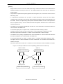
Operation Flow of ld850 ... 153
ld850 Operation Image (Example) ... 154
Batch Processing ... 154
Modular Processing ... 154
Creation of Output Section ... 155
Allocation to Memory Space ... 155
[Linker Options] Dialog Box ... 170
[Linker Options] Dialog Box ([File] Tab) ... 171
[Linker Options] Dialog Box ([Library] Tab) ... 172
[Library List] Dialog Box ... 173
[Linker Options] Dialog Box ([Option] Tab) ... 174
[Linker Options] Dialog Box ([Others] Tab) ... 177
Link Map Output Example ... 179
In Fixed ROM ... 182
In Flash Memory ... 182
From Fixed ROM to Flash Memory ... 183
From Flash Memory to Fixed ROM ... 184
Compiler Common Options for Flash Memory ... 191
Compiler Common Options for Fixed ROM ... 191
Memory Allocation Image of gp Offset Reference Section ... 194
User’s Manual U18512EJ1V0UM
5 - 21
5 - 22
6-1
6-2
6-3
6-4
6-5
6-6
6-7
6-8
6-9
6 - 10
6 - 11
6 - 12
6 - 13
6 - 14
7-1
7-2
7-3
7-4
7-5
7-6
7-7
8-1
8-2
9-1
9-2
9-3
9-4
9-5
9-6
10 - 1
10 - 2
10 - 3
10 - 4
11 - 1
11 - 2
12 - 1
12 - 2
12 - 3
12 - 4
12 - 5
12 - 6
12 - 7
12 - 8
12 - 9
12 - 10
12 - 11
12 - 12
12 - 13
12 - 14
12 - 15
12 - 16
13 - 1
13 - 2
13 - 3
13 - 4
13 - 5
13 - 6
14 - 1
14 - 2
14 - 3
14 - 4
Example of Output Information on Executable Object File ... 195
Example of Output Information on Relocatable Object File ... 196
Creation of Object for ROMization ... 204
Image of Processing Immediately After _rcopy Function Call ... 205
Link Directive Taking ROMization Processing into Consideration ... 210
Link Directive Taking ROMization Processing into Consideration (Size Considered) ... 211
Example of Using Copy Function _rcopy 1 ... 212
ROMization Image 1 ... 214
Example of rompack.s ... 215
Example of Using Copy Function _rcopy 2 ... 215
Link Directive Specification Example ... 216
ROMization Image 2 ... 217
[ROM Processor Options] Dialog Box ([File] Tab) ... 232
[ROM Processor Options] Dialog Box ([Section] Tab) ... 233
[ROM Processor Options] Dialog Box ([Option] Tab) ... 235
[ROM Processor Options] Dialog Box ([Others] Tab) ... 237
Operation Flow in hx850 ... 238
[Hexa Converter Options] Dialog Box ([File] Tab) ... 248
[Hexa Converter Options] Dialog Box ([Option] Tab) ... 249
[Hexa Converter Options] Dialog Box ([Others] Tab) ... 252
File Configuration in Intel Expanded Hex Format ... 253
File Configuration of Motorola S Type Hex Format ... 257
File Configuration of Expanded Tek Hex Format ... 259
The ar850’s Operation Flow ... 263
[Archiver Options] Dialog Box ([Option] Tab) ... 270
Image of Compilation Using Section File Specifications ... 273
Example of Section File Output by sf850 ... 275
Example of Section File Output by sf850 Using -O Option ... 276
[Section File Generator Options] Dialog Box ([File] Tab) ... 288
[Section File Generator Options] Dialog Box ([Option] Tab) ... 289
[Section File Generator Options] Dialog Box ([Others] Tab) ... 292
Operation Flow of dump850 ... 293
[Object Analysis Tool] Dialog Box ([Dump] Tab) ... 298
[Output Index] Dialog Box ... 302
[Archive File Options] Dialog Box ... 303
Operation Flow of dis850 Command ... 313
[Object Analysis Tool] Dialog Box ([Disassembler] Tab) ... 318
Flow of Operation in cxref ... 323
[Static performance analyzer] Dialog Box (Cross reference) ... 337
[Cross reference option] Dialog Box ([Common option] Tab) ... 341
[Cross reference option] Dialog Box ([Cross reference list] Tab) ... 344
[Cross reference option] Dialog Box ([Tag information] Tab) ... 345
[Cross reference option] Dialog Box ([Call graph] Tab) ... 346
[Cross reference option] Dialog Box ([Function measure] Tab) ... 349
[Cross reference option] Dialog Box ([Call database] Tab) ... 351
Cross Reference Output Example (cxref) ... 353
Tag Information Output Example (cxref) ... 355
Call Tree Text-Format Output Example (cxref) ... 357
Call Tree CSV-Format Output Example (cxref) ... 358
Function Metrics Text-Format Output Example (cxref) ... 360
Function Metrics CSV-Format Output Example (cxref) ... 361
Call Database Text-Format Output Example (cxref) ... 363
Call Database CSV-Format Output Example (cxref) ... 364
Flow of Operation in rammap ... 366
[Static performance analyzer] Dialog Box ([RAM map] Tab) ... 373
[RAM map option] Dialog Box ([Common option] Tab) ... 376
[Object Analysis Tool] Dialog Box ([RAM map] Tab) ... 379
Memory Map Table Text-Format Output Example (rammap) ... 381
Memory Map Table CSV-Format Output Example (rammap) ... 382
Estimation Flow in stk850 ... 383
Main Window of st850 ... 388
[Adjust Stack Size] Dialog Box ... 392
[Stack Size Unknown / Adjusted Function Lists] Dialog Box ... 394
User’s Manual U18512EJ1V0UM
17
14 - 5
A-1
B-1
18
[About stk850] Dialog Box ... 396
Object File Structures ... 406
Example of Message Dialog Box ... 486
User’s Manual U18512EJ1V0UM
LIST OF TABLES
Table No. Title Page
3-1
3-2
3-3
3-4
3-5
3-6
3-7
3-8
4-1
4-2
4-3
4-4
4-5
5-1
5-2
6-1
6-2
6-3
7-1
7-2
7-3
8-1
9-1
9-2
9-3
9-4
10 - 1
11 - 1
12 - 1
12 - 2
13 - 1
13 - 2
13 - 3
14 - 1
14 - 2
14 - 3
14 - 4
14 - 5
14 - 6
14 - 7
14 - 8
14 - 9
14 - 10
14 - 11
A-1
A-2
A-3
A-4
A-5
A-6
A-7
A-8
B-1
B-2
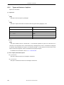
Register Mode ... 49
Correspondence Between CPU Core and -Xv850patch Option for This Bug ... 63
[Compiler Common Options] Dialog Box ... 69
[Compiler Common Options] Dialog Box (library) ... 69
[Compiler Options] Dialog Box ... 80
[Compiler Options] Dialog Box (Individual Source) ... 80
Message Numbers of Messages That Can Be Specified ... 106
Optimization Processing and Items ... 117
[Assembler Options] Dialog Box ... 136
[Assembler Options] Dialog Box (Individual Source) ... 136
Section Attributes and Their Meanings ... 145
Correspondence Between CPU Core and -p Option ... 149
Correspondence Between Created Objects and -p Options ... 152
Reserved Section ... 198
Special Symbols in Ordinary Object File ... 198
Reserved Sections Packed by romp850 ... 208
Copy Routines ... 218
[ROM Processor Options] Dialog Box ... 231
HEX Format Block/Record ... 243
[Hexa Converter Options] Dialog Box ... 247
HEX Format Block/Record ... 251
[Archiver Options] Dialog Box ... 269
Variable Types and Displays ... 275
Variable Displays and Their Meanings ... 276
Types of Sections Specifiable by ca850 ... 277
[Section File Generator Options] Dialog Box ... 287
[Object Analysis Tool] Dialog Box (dump850) ... 297
[Object Analysis Tool] Dialog Box (dis850) ... 317
[Static performance analyzer] Dialog Box (cxref) ... 336
[Cross reference Option] Dialog Box ... 340
[Static performance analyzer] Dialog Box (rammap) ... 372
[RAM map option] Dialog Box ... 375
[Object Analysis Tool] Dialog Box (rammap) ... 378
Windows and Dialog Boxes of stk850 ... 386
Function Icons for stk850 ... 390
Project File Related Upper Limit Values ... 397
Intermediate Assembly Language File Related Upper Limit Values ... 397
Stack Size Specification File Related Upper Limit Values ... 397
Output File Related Upper Limit Values ... 398
Stack Size Related Limit ... 398
Upper Limit Values in Message Display Area ... 398
Description for Each Parameter ... 399
Output Format and Content of Adjustment Information ... 400
Description for Each Parameter ... 402
Constituent Elements of ELF Header and Their Meanings ... 407
Constituent Elements of Program Header Table Entries and Their Meanings ... 408
Constituent Elements of Section Header Table Entries and Their Meanings ... 409
Section Types and Their Meanings ... 410
Meanings of Link and Info ... 410
Constituent Elements of Symbol Table Entries and Their Meanings ... 411
Relationship Between Indexes and Character Strings in String Table ... 412
Reserved Sections ... 413
Formats of Messages Output by stk850 ... 493
[Do you want to stop reading?] Dialog Box ... 494
User’s Manual U18512EJ1V0UM
19
CHAPTER 1 OVERVIEW
CHAPTER 1 OVERVIEW
1.1
Features of Compiler Package
The C compiler package for the V850 microcontrollers contains the following programs.
1.
C COMPILER (ca850)
2.
ASSEMBLER (as850)
3.
LINKER (ld850)
4.
ROMIZATION PROCESSOR (romp850)
5.
HEXADECIMAL CONVERTER (hx850)
6.
ARCHIVER (ar850)
7.
SECTION FILE GENERATOR (sf850)
8.
DUMP COMMAND (dump850)
9.
DISASSEMBLER (dis850)
10.
CROSS REFERENCE TOOL (cxref)
11.
MEMORY LAYOUT VISUALIZATION TOOL (rammap)
12.
STACK USAGE TRACER (stk850)
13.
LINK DIRECTIVE GENERATOR (LDG)
These programs can be activated in either of the following ways.
(1)
Activating from integrated development environment "PM+"
"PM+" is included in the C compiler package.
For details of PM+, refer to PM+ User’s Manual.
(2)
Activating from command line
Activate the C compiler package by inputting a command in response to the command prompt.
To generate a load module file by using a batch file or make file, describe the module in the command
input format. Utilities 8 to 11 above can also be activated by inputting a command.
For details on command input methods, refer to the section "Operation Method" for the respective tool.
20
User’s Manual U18512EJ1V0UM
CHAPTER 1 OVERVIEW
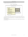
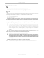
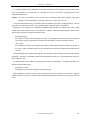
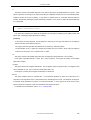
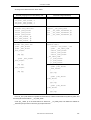
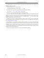
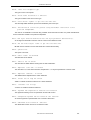
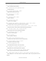
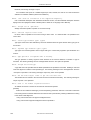
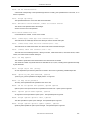
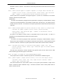
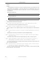
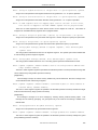
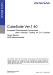
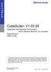
The package configuration is as shown below when PM+ is used.
Figure 1 - 1 Package Configuration
CA850 package command
C compiler
Assembler
Linker
ROMization processor
Hexadecimal converter
Archiver
Section file generator
Cross-reference tool
Memory layout visualization tool
Dump command
Dissassembler
Command prompt
Stack usage tracer
Link directive generator
PM+
Specify the options of the C compiler, assembler, linker, and so on that are included in the "CA850 package
commands" above on the relevant windows from PM+. PM+ automatically activates these commands and
creates a load module file.
To use the CA850, a device file that has device information is necessary. Obtain the device file corresponding
to the device to be used.
User’s Manual U18512EJ1V0UM
21
CHAPTER 1 OVERVIEW
1.2
Operating Environments
The Windows version C compiler package operates under the following environments.
(1)
Host machine
- CPU:
Pentium IITM 400MHz or higher
- Memory:
128 M bytes or more
- OS:
Windows® 2000, Windows XP Professional, Windows XP Home Edition
Caution
(2)
Regardless of which OS is used, higher and the latest Service Pack must be installed.
Related development tools
- Integrated debugger
ID850 (Ver.3.10 or later), ID850NW (Ver.3.10 or later), or ID850QB (Ver.3.10 or later)
- System simulator
SM850 (Ver.3.00 or later), or SM+ for V850 (Ver.2.00 or later)
- Performance analysis tuning tool
TW850 (Ver.2.10 or later)
- Real-time OS
RX850 (Ver.3.20 or later), RX850 Pro (Ver.3.20 or later)
- Task debugger
RD850 (Ver.3.20 or later), RD850 Pro (Ver.3.20 or later)
- System performance analyzer
AZ850 (Ver.3.30 or later)
- Device file installer
DFINST (Ver.3.10 or later)
Caution
To use the CA850, a device file which includes the device information is required.
Download the device file of target device to be used from the following web site:
http://www.necel.com/micro/ods/eng/index.html
22
User’s Manual U18512EJ1V0UM
CHAPTER 2 INSTALLATION
CHAPTER 2 INSTALLATION
This chapter describes the installation and uninstallation of the CA850.
2.1
Installation
To use the CA850, both the CA850 itself and the related device files must be installed.
To use PM+, PM+ must also be installed.
Install the CA850 as follows.
The supply medium is one CD-ROM.
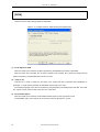
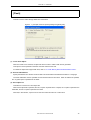
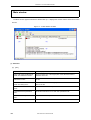
(1)
Start Windows.
(2)
Insert the CD-ROM into the CD-ROM drive.
The setup program starts up automatically. If the setup program does not start, start Windows Explorer,
and double-click "Install.exe" in the CD-ROM drive.
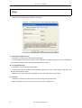
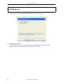
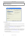
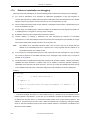
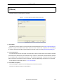
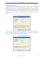
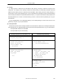
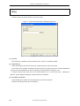
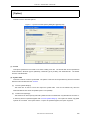
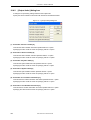
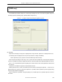
(3)
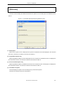
Select the tool to be installed (CA850, PM+, STK850, LDG, etc.), and specify the folder in which the tool
is to be installed. Then, click the [Install] button
(4)
Note
Execute installation in compliance with the messages displayed on the screen.
Install the device file in compliance with the device file installer (DFINST) that has been installed.
User’s Manual U18512EJ1V0UM
23
CHAPTER 2 INSTALLATION
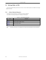
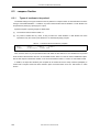
2.2
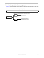
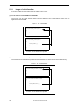
Folder Organization
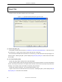
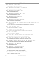
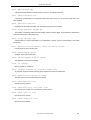
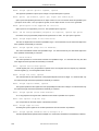
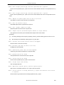
Figure 2 - 1 shows the organization of the file folder that is read from the supply medium when the CA850 is
installed.
Below is the CA850’s standard folder (default).
C:\Program Files\NEC Electronics Tools\CA850\Vx.xx
In the CA850 package, the lib850 folder shown in Figure 2 - 1 is called the standard folder for the library, and
the inc850 folder is called the standard folder for include files.
Below is the standard folder for the device files (default).
C:\Program Files\NEC Electronics Tools\DEV
Figure 2 - 1 Folder Organization
bin
Command group
inc850
Include file group
lib
lib850
Install Folder
smp850
24
Module group internally called by C compiler
r22
Library (for 22-register mode)
startup module
r26
Library (for 26-register mode)
startup module
r32
Library (for 32-register mode)
startup module
r32msk
Library (for 32-register mode
with mask register support)
startup module
ca850
Link directive sample
hlp
Online help
doc
Online manual
User’s Manual U18512EJ1V0UM
CHAPTER 2 INSTALLATION
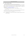
2.2.1
Folder organization of stack usage tracer
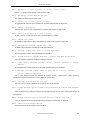
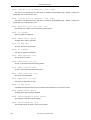
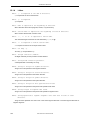
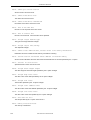
Figure 2 - 2 shows the organization of the file folder that is read from the supply medium when the stack usage
tracer is installed.
Below is the standard folder for the stack usage tracer (default).
C:\Program Files\NEC Electronics Tools\STK850\Vx.xx
Figure 2 - 2 Folder Organization of Stack Usage Tracer
bin
Command group
Install Folder
dat850
Stack size specification file
for standard library functions
User’s Manual U18512EJ1V0UM
25
CHAPTER 2 INSTALLATION
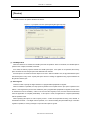
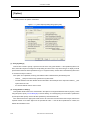
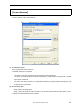
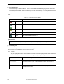
2.3
Uninstallation
This section describes the method for uninstallation of the CA850.
(1)
Start Windows.
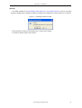
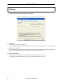
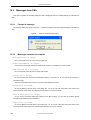
(2)
Start "Add or Remove Programs" ("Add/Remove Programs" in Windows other than Windows XP) on the
Control Panel of Windows
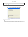
(3)
Select the following items.
- NEC EL CA850 Vx.xx
- NEC EL CA850 Vx.xx Documents
Remark Other tools (PM+, STK850, LDG, etc.) and documents can be uninstalled in a similar way.
26
User’s Manual U18512EJ1V0UM
CHAPTER 3 C COMPILER
CHAPTER 3 C COMPILER
This chapter provides an overview and explains the operation and output messages of the C compiler (ca850).
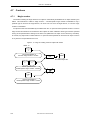
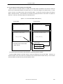
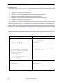
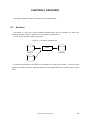
3.1
Flow of Operation
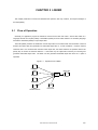
The ca850 creates relocatable object files and object files executable on the target system from C language
source programs described in C language source files.
The ca850 acts as the driver of the modules included in the package and performs operations such as macro
expansion, comment processing, merging of intermediate-language files, optimization, creation/conversion from
assembly-language source programs to machine language instructions, and linking of object files.
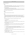
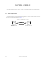
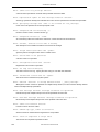
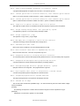
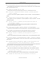
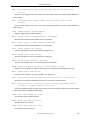
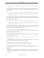
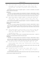
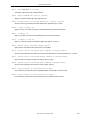
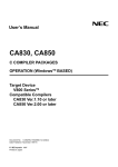
The ca850 performs processing in the following sequenceNote (refer to Figure 3 - 1 ).
Note
As is shown in Figure 3 - 1, the processing flow varies slightly depending on the specified optimization
level.
(1)
The front end (cafe) performs macro expansion and comment processing of a C language source program
and then converts the program into an intermediate-language OPTIC program.
(2)
The pre-optimizer (popt) rearranges the functions in the intermediate-language OPTIC program.
If this command is activated from the command line, and if "File merging option (-Om)" is specified, two or
more intermediate-language OPTIC programs are merged into one. If "Level 2 Advanced option (Exec.
Speed)" is specified, inline expansion is performed for the functions in the intermediate-language OPTIC
program.
(3)
The global optimization module (opt) optimizes the intermediate-language OPTIC program.
(4)
The code generation module (cgen) converts the intermediate-language OPTIC program into an assemblylanguage source program.
(5)
The machine-dependent optimization module (impr) optimizes the assembly-language source program.
(6)
The assembler (as850) converts the assembly-language source program into machine language
instructions and creates a relocatable object file.
(7)
The linker (ld850) links the relocatable object file, and creates an executable object file.
The machine-dependent optimization module are called only when the optimization option is specified
(refer to Figure 3 - 1). It is assumed that the modules of (1) front end (cafe) through (5) machinedependent optimization module (impr) are started from the ca850.
Consequently, operation is not
guaranteed if any of these modules is started alone.
User’s Manual U18512EJ1V0UM
27
CHAPTER 3 C COMPILER
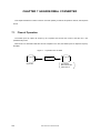
Figure 3 - 1 Operation Flow of ca850
.c
Code generation module
Front end
.s
.ic
-Od/-Og/Default(-Ob)
specified
-O/-Os/-Ot specified
-Om not specified
-Om specified
NO
Machine-dependent
optimization module
Input file
processing
completed
YES
.s
Pre-optimizer
Assembler
.ic
.o
-Om specified
-Om not specified
Global optimization module
NO
.ic
Input file
processing
completed
YES
.a
Linker
.out
28
User’s Manual U18512EJ1V0UM
CHAPTER 3 C COMPILER
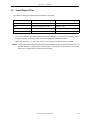
3.2
Input/Output Files
The ca850 can specify the following files as input files or output files.
-
file.c
C language source file
called the .c file
file.ic
OPTIC file
called the .ic file
file.s
assembly language source file
called the .s file
file.o
object file
called the .o file
file.a
archive file
called the .a file
The .s file is passed to the as850 (assembler) without modification (a source program directly coded in
assembly language does not go through the machine-dependent optimization module).
-
All the files other than .c, .ic, and .s files, such as .a and .o files, are all passed as is to the ld850
Caution The input file names supported by Windows can be specified, but "@" cannot be used at the head of a
file name because it is regarded as a command option. If the Kanji code of the file is EUC, a file name,
folder name, or folder name in Japanese cannot be used.
User’s Manual U18512EJ1V0UM
29
CHAPTER 3 C COMPILER
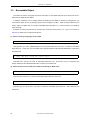
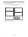
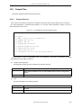
3.3
Executable Object
The ca850 can read a C language source file and create an executable object file at the same time since it
starts both the as850 and the ld850.
In addition, processing can be stopped before the as850 and the ld850 are started by specifying the (-S)
command line option and or by specifying single source compilation via PM+. Either of these methods can be
used to output a compiler code or to create a relocatable object file (refer to "3.4 Operation Method" for details of
these methods).
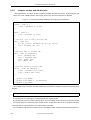
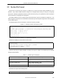
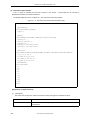
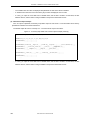
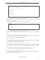
Examples of starting commands from command line are shown below (refer to "3.5 Types and Features of
Options" for details of the command line options).
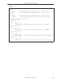
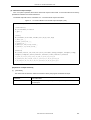
(1) When executing everything from the ca850
> ca850 -cpu 3201 file.c obj.o
This specifies "-cpu 3201" (V850ES/SA2) as the device and reads file.c and obj.o to create an executable
object file a.out. At this time, crtE.o is linked as the startup module and the standard libraries libc.a and libm.a
are referenced.
> ca850 -cpu 3201 -R org_crt.o file.c obj.o
This reads file.c and obj.o to create an executable object file a.out. At this time, org_crt.o is linked as the
startup module and the standard libraries libc.a and libm.a are referenced.
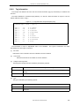
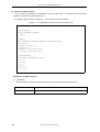
(2) When starting from the ca850 to the as850, and starting the ld850 alone
> ca850 -cpu 3201 -c file.c asm.s
This reads file.c and asm.s to create the relocatable object files file.o and asm.o.
> ld850 -cpu 3201 org_crt.o file.o asm.o obj.o -lc
This links org_crt.o, file.o, asm.o, and obj.o to create the executable object file a.out. At this time, libc.a is
referenced.
30
User’s Manual U18512EJ1V0UM
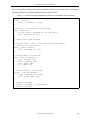
CHAPTER 3 C COMPILER
(3) When starting the ca850, the as850, and the ld850 by themselves
> ca850 -cpu 3201 -c file.c
This reads file.c to create the relocatable object file file.o.
> as850 -cpu 3201 asm.s
This reads asm.s to create the relocatable object file asm.o.
> ld850 org_crt.o file.o asm.o -lc
This links org_crt.o, file.o, and asm.o to create the executable object file a.out.
At this time, libc.a is
referenced.
User’s Manual U18512EJ1V0UM
31
CHAPTER 3 C COMPILER
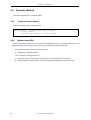
3.4
Operation Method
This section explains how to operate the ca850.
3.4.1
Command input method
Enter the following from the command prompt.
ca850 [option] ... file name [file name or option] ...
[ ] : Can be omitted
... : Pattern in proceeding [ ] can be repeated.
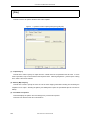
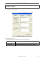
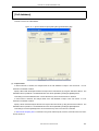
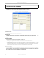
3.4.2
Method using PM+
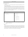
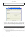
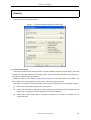
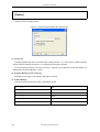
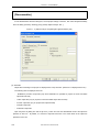
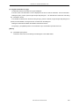
The [Compiler Options] dialog box that is used to set compiler options for the C language source files can be
displayed via either of the following methods once a project has been established under PM+.
-
Set for all C language source files of the target project
(1)
-
32
Select [Tool] - [Compiler Options...].
Set for a specific C language source file
(1)
Select the name of the source file to be set a option in the [Project] window on the PM+.
(2)
Select [Individual Compiler Options...] item that is displayed by clicking the right mouse button.
User’s Manual U18512EJ1V0UM
CHAPTER 3 C COMPILER
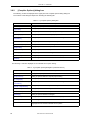
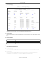
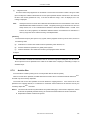
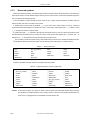
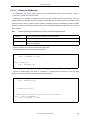
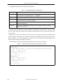
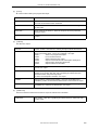
3.5
Types and Features of Options
The following table lists the ca850 options.
When starting from the command line, if an option that is not listed in the following table is given, that option is
regarded as an ld850 option and is passed to the ld850 without modification.
Some options listed below are not included in the PM+'s option dialog box. When one of these options must
be specified, activate the ca850 from the command line.
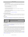
[Symbols used in option list]
[V850E2]
Option dedicated to V850E2 core
[V850E]
Option dedicated to V850Ex core
[PM+]
Option exists as specification item under the PM+.
[78K-compatible]
Option compatible with 78K microcontrollers C compiler CC78Kx
User’s Manual U18512EJ1V0UM
33
CHAPTER 3 C COMPILER
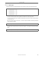
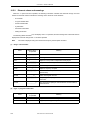
3.5.1
Version/help display/operation status
Version/help display/operation status options are shown below.
-V
This option outputs ca850’s version information to standard error output. It does not execute compilation.
-help
This option outputs an option description to standard error output.
-v
[PM+]
This option outputs the execution status of the ca850 to the standard error output in detail.
34
User’s Manual U18512EJ1V0UM
CHAPTER 3 C COMPILER
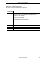
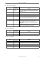
3.5.2
Output file specification
This section describes the options that specify an output file.
-Fic[=outfile]
This option specifies where an OPTIC file generated during compilation is to be saved.
(a)
If the file name is specified as outfile
Saves the outfile to the current folder under the specified file name.
The extension of outfile is restricted to ".ic"
(b)
If the folder is specified as outfile
Saves the outfile under a file name with extension .c replaced by .ic to the specified folder.
(c)
If =outfile is omitted
Saves the outfile under a file name with extension .c replaced by .ic to the current folder.
(d)
If two or more files are output
Creates a folder specified for outfile, and saves the OPTIC file under a file name with extension .c
replaced by .ic.
-Fo[=outfile]
This option specifies where an object file generated in the middle of compiling is to be saved.
(a)
If the file name is specified as outfile
Saves the outfile to the current folder under the specified file name.
(b)
If the folder is specified as outfile
Saves the outfile under a file name with extension .c or .s replaced by .o to the specified folder.
(c)
If =outfile is omitted
Saves the outfile under a file name with extension .c or .s replaced by .o to the current folder.
(d)
If two or more files are output
Creates a folder specified as outfile, and saves the object file under a file name with extension .c or .s
replaced by .o.
-Fs[=outfile]
[PM+]
This option specifies where an assembly language file generated in the middle of compiling is to be saved.
(a)
If the file name is specified as outfile
Saves the outfile to the current folder under the specified file name.
(b)
If the folder is specified as outfile
Saves the outfile under a file name with extension .c replaced by .s to the specified folder.
(c)
If =outfile is omitted
Saves the outfile under a file name with extension .c replaced by .s to the current folder.
(d)
If two or more files are output (this cannot be specified with PM+)
Creates a folder specified as outfile, and saves the object file under a file name with extension .c
replaced by .s.
User’s Manual U18512EJ1V0UM
35
CHAPTER 3 C COMPILER
-Fv[=outfile]
[PM+]
This option specifies whether an assemble list generated in the middle of compiling is to be saved.
(a)
If the file name is specified as outfile
Saves the outfile to the current folder under the specified file name.
(b)
If the folder is specified as outfile
Saves the outfile under a file name with extension .c or .s replaced by .v to the specified folder.
(c)
If =outfile is omitted
Saves the object file under a file name with extension .c or .s replaced by .v to the current folder.
(d)
If two or more files are output (this cannot be specified with PM+)
Creates a folder specified as outfile, and saves the outfile under a file name with extension .c or .s
replaced by .v.
If this option and the -a option are not specified, an assemble list will not be generated.
-o outfile
This option specifies an output file as outfile. It is valid even if compiling is stopped midway by specifying
the compiler control option -S, -c, or -m.
(a)
If this option is specified with the -S option
An assembler file (.s) is specified.
(b)
If this option is specified with the -c option
A relocatable object file (.o) is specified.
(c)
If this option is specified with the -m option
A front-end output file (.ic) is specified.
(d)
Other than above
An executable object file (.out) is specified.
(e)
The default assumption is a.out.
An error occurs.
-temp=dir
[PM+]
This option specifies the work folder for creating temporary files that are used internally. If this option is
omitted, temporary files are generated in a folder specified by environmental variable TEMP or a root folder in
the current drive.
If the capacity of the hard disk runs short and a temporary file cannot be generated, an error occurs. This
error can be avoided by using this option.
36
User’s Manual U18512EJ1V0UM
CHAPTER 3 C COMPILER
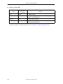
3.5.3
Controlling source debugger
The following options are used to control the source debugger.
-Xno_word_bitop
[PM+]
This option prohibits replacing the ld.w/ld.h and st.w/st.h instructions with 1-bit manipulation instructions
(set1, clr1, tst1, and not1). If a read/write event of a variable is set during debugging, an event may not be
generated if these instructions are replaced by 1-bit manipulation instructions. If this option is specified in such
a case, the ld.w/ld.h and st.w/st.h instructions are not replaced by 1-bit manipulation instructions, making
debugging easy.
-g
[PM+]
This option outputs symbol information for the source debugger. When the as850 is started via the ca850,
specification of this option is regarded as the same as specifying the as850's "-g" option. As a result,
assembly language source debugging is performed by the debugger.
User’s Manual U18512EJ1V0UM
37
CHAPTER 3 C COMPILER
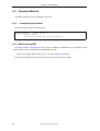
3.5.4
Control of compile driver
Control of compile driver options are shown below.
(1) Options related to device specification
-X256M
[V850E] [PM+]
This option treats the memory space as 256 M bytes. If this option is not specified, address resolution is
performed, assuming that the memory space is 64 M bytes. Set this option in accordance with the chipset to
be used.
The physical address space of the V850Ex core has 256 M bytes in many cases. When creating an
application that uses a space between 64 M bytes and 256 M bytes, specify this option.
-Xbpc=num
[PM+]
This option sets the higher address of the programmable peripheral I/O register. In num, specify only the
part of address from which the highest bit of the BPC register is removed.
If the target device has programmable peripheral I/O register functions (such as V850E/IA1), the value must
be determined when compiling (assembling) the application to set the variable address portion (= value set in
BPC register). Thus, specifying this option compiles (assembles) using the specified value.
When specifying this option, be sure to specify a value. A binary, octal, decimal, or hexadecimal number
can be used for the value. If an invalid value is specified, or if a value outside the range that can be set in the
BPC register is specified, a warning message is output and this option is ignored.
Example
-Xbpc=0x1234
In the above case, if the target device is the V850E/IA1, the start address of the programmable peripheral I/
O register area is treated as this value shifted 14 bits to the left, or 0x48d0000.
One value is set for an entire application. If you specify "-Xbpc" or "-bpc" when setting options by file, make
the values the same between files. However, this option need not be specified for files that do not use the
programmable peripheral I/O register.
If this option is specified for a target device that does not have programmable peripheral I/O register
functions or when assembling as a common for V850 core/V850Ex core/V850E2 core, a warning message is
output and this option is ignored.
This option is for determining the address of the programmable peripheral I/O register when compiling
(assembling) and does not actually cause a value to be reflected in the BPC register. For operation, it is
necessary to set a value in the BPC register separately using a startup module or the like. A sample appears
(commented out) in the startup module included in the package.
38
User’s Manual U18512EJ1V0UM
CHAPTER 3 C COMPILER
Example
For the V850E/IA1, specify the following descriptions in the startup module to make the variable portion of
the start address of the programmable peripheral I/O register "0x1234" and set the flag 0x8000 that enables
the use of this function.
mov0x9234, r10 - - 0x1234 | 0x8000 = 0x9234
st.hr10, BPC
The as850 outputs a .bpc section in the special reserved sections when the programmable peripheral I/O
register is referenced, regardless of whether this option is specified or omitted. This section is used for
checking when linking. The .bpc section is a special reserved section for information and is never loaded into
memory. Therefore, it need not be specified in a link directive like a normal section.
-cn
This option embeds the magic number of common to V850 core into the object to be generated.
For further description of magic numbers, refer to "4.7.1 Magic number".
-cnv850e
[V850E]
This option embeds the magic number of common to V850Ex core into the object to be generated.
-cnv850e2
[V850E2]
This option embeds the magic number of common to V850E2 core into the object to be generated.
-cpu devicename
This option specifies the target deviceNote. When using PM+, this is equivalent to specifying the device on
the [Project Information] of the [Project Settings] wizard. If this option is omitted and nothing has been
specified by the -cn option, -cnv850e option, -cnv850e2 option or #pragma directive, compilation is stopped.
Note
This has the same function as "#pragma cpu devicename". There are two methods: specification by
the -cpu option or specification by the #pragma directive. If both are specified but have different
contents, the specification by the -cpu option has priority.
-devpath=dir
This option searches a device file from the folder dir. Only the standard folders are searched if this option is
omitted. When using PM+, the device file's installation folder is automatically set, so there is no need to be
aware of this option.
User’s Manual U18512EJ1V0UM
39
CHAPTER 3 C COMPILER
(2) Compiler control specification options
-S
This option outputs the generated assembly language source program without executing any modules
under the as850. The output file uses .s as the extension instead of .c. If this option is omitted, modules
following the as850 are also executed. However, modules under the as850 are also executed if this option
has been specified via PM+. To avoid executing those modules, compile source files one at a time.
-a
This option outputs an assemble list to a file whose extension .c is changed to .v (refer to "4.6 Assemble
List"). When the -Og, -O, -Os, or -Ot option is specified, a part of the assemble list may be incorrectly output
due to instruction rearrangement for optimization by the as850.
By using this option (-Fv option) with PM+, a file name on the assemble list can be specified.
-c
This option outputs the object file without starting the ld850. The file name extension is .o instead of .c or .s.
The ld850 is started if this option is omitted. When PM+ is used, this option is automatically specified for all
compilation.
-m
This option simply executes the front end, generates an .ic file, then terminates processing. If this option is
omitted, modules after the front end are also executed.
(3) ROMization control option
-Xr
[PM+]
This option is necessary when creating an object for ROMization, and starts up the ROMization processor
after link processing.
The created object file (default name: romp.out) is the file with the ROMization
information.
The compiler processing is as follows.
(a)
The label of the first argument for _rcopy specifies the first address (aligned according to the four-byte
alignment condition) that exceeds the end of the .text section in the object.
(b)
Consequently, this specifies the area securing code for the rompsec section (default name: rompcrt.o)
and the libr.a file to be linked by the linker (ld850).
Refer to "6.4 Creating Object for ROMization" for details of ROMization object creation methods.
40
User’s Manual U18512EJ1V0UM
CHAPTER 3 C COMPILER
(4) Preprocessor processing setting options
-C
[PM+]
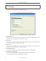
The -C option includes source program comments in a C language source program’s preprocessing output.
This option is valid only when either the -E option or the -P option has been specified.
-Dname[=def]
[PM+]
When this option is specified, it is assumed that #define name def is entered before the C language source
program. If the =def specification is omitted, the def value is regarded as 1. Up to 256 of this options can be
specified.
-E
This option executes preprocessing only for a C language source program and outputs the results to
standard output. The results include the line numbers and file name of the source program.
-Idir
[PM+]
This option searches the folder dir and the standard folder, in that order, for the header file of a C language
source program. Up to 100 of this option can be specified. If this option is omitted, only the standard folder is
searched.
The standard folder is the install folder \inc850 folder. If #include "header file name" is described, the folder
where the source file is stored is searched first.
-P
This option executes preprocessing only for a C language source program and outputs the results to a file
whose name is the C language source file name plus .i as the extension instead of .c.
The source program’s line numbers and file name are not output.
-Uname
[PM+]
When this option is specified, it is assumed that #undef name is coded before the C language source
program. Up to 256 of this options can be specified.
-Wa,-Dname[=num]
[PM+]
When this option is specified, it is assumed that .set name, num is entered before the assemble source.
If the =num specification is omitted, the num value is regarded as 1.
-Wa,-I,dir
[PM+]
This option searches the folder dir and the standard folder, in that order, for the header file of an assembly
language file. If this option is omitted, only the standard folder is searched.
User’s Manual U18512EJ1V0UM
41
CHAPTER 3 C COMPILER
-Xcxxcom
[PM+]
In addition to ordinary comments, this interprets all characters that appear after "//" and before the end of the
line as comments (C++ comment style).
-Xd
This option outputs a warning message in response to initialization of a pointer type external variable which
uses a variable address that is not an automatic variable or which uses a function address.
-Xmnum
[PM+]
This option specifies an upper limit for the number of macro identifiers. A decimal value up to 32767 can be
specified as num. A default value of 2047 is used if this option is omitted.
This option increases the size of the buffer used by the preprocessor. However, this option cannot be used
to set a specific value for buffer size in terms of the number of characters the buffer can contain.
-t
[PM+]
This option replaces a trigraph sequence.
This option specifies a three-character (trigraph) string to be replaced by a single character defined by the
ANSI standard. For details, refer to the documents related to the ANSI standard.
(5) Options to save memory during compilation
-Wp,-D
[PM+]
This option reduces memory in pre-optimizer phase during compiling.
Specify this option if compiling is not completed correctly because the memory of the machine runs short.
The compilation speed drops when this option is specified.
-Wi,-D
[PM+]
This option reduces the memory capacity used in the machine dependent optimization phase during
compiling. Specify this option if compiling is not completed correctly.
The compilation speed drops when this option is specified.
42
User’s Manual U18512EJ1V0UM
CHAPTER 3 C COMPILER
(6) Error output specification options
+err_file=file
This option adds and saves error messages to the file file. With PM+, specifying a file name as "Error File"
on the [File] in the [Compiler Common Options] dialog box is equivalent to specifying this option.
-err_file=file
This option overwrites and saves error messages to the file file.
-err_limit=num
[PM+]
This option specifies the maximum number of error message to be output, num.
Specify 15 to 50 in decimal numbers as num. If this option is omitted, 15 is assumed.
(7) Expansion function specification option
-cc78k
[78K-compatible] [PM+]
This option enables the expansion functions compatible with the 78K microcontrollers C compiler CC78Kx.
User’s Manual U18512EJ1V0UM
43
CHAPTER 3 C COMPILER
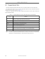
3.5.5
Optimization
"Optimization" is processing used to increase the execution speed of an application or to decrease the ROM
capacity to be used. How optimization is performed differs depending on the level of optimization. If a high level
of optimization is selected, the compilation speed may slow down and the probability of allocating C language
source lines to be deleted or changed and variables to registers increases. In the latter case, phenomena such
as being unable to set breakpoints with the debugger may occur, and the debugging efficiency may be affected.
For details of optimization, refer to "3.7.3 Efficient use of optimization".
(1) Optimization options
-Od
[PM+]
Optimize for Debugging option
This option generates codes emphasizing logic debugging, without putting stress on the ROM capacity and
execution speed. Its function is equivalent to the default optimization of CA850 Ver. 2.41 or earlier.
-Ob
[PM+]
Default Optimization option
This option generates codes emphasizing logic debugging. It executes optimization within a range where
logic debugging is not affected
-Og
[PM+]
Standard Optimization option
This option executes appropriate optimization. It executes optimization that allows debugging of the C language source in most cases. Because external variables are assigned to registers, both the execution speed
and code size are improved from those of the default option.
-O
[PM+]
Level 1 Advanced Optimization option
This option executes optimization emphasizing the ROM capacity.
-Os
[PM+]
Level 2 Advanced (Object Size) option
This option executes the maximum optimization placing the utmost emphasis on the ROM capacity.
-Ot
[PM+]
Level 2 Advanced (Exec. Speed) option
This option executes the maximum optimization placing the utmost emphasis on the execution speed rather
than on the ROM capacity.
44
User’s Manual U18512EJ1V0UM
CHAPTER 3 C COMPILER
(2) Target code optimization options
-Wi,-O4
[PM+]
This option strictly analyzes the data flow and executes the most advanced optimization. Specify this
option, in addition to the optimization option -O, -Os, or -Ot, to execute more advanced optimization.
Specifically, this option executes optimization as follows.
-
Optimization of registers extending over a branch instruction
-
Optimization of absolute value operations
-
Optimization of a cmp instruction extending over a branch instruction
-
Optimization of a return instruction extending over a branch instruction
Depending on the source, the result may be the same as that of -Os or -Ot. The compiling time is longer
than that of -Os or -Ot.
-Wi,-P
[PM+]
This option prevents optimization that allows branch destination labels to be aligned. This option can
reduce the size of the execution code. It is useful when the Level 2 Advanced option (Exec. Speed) -Ot is
specified.
(3) File merging option
-Om
When two or more files are specified at the same time, this option merges the files. The compiling speed
will drop, but the optimization application range of such as optimization between functions can be expanded by
specifying this option together with the optimization option -O, -Os or -Ot.
However, source debugging will become difficult.
(4) Inline expansion optimization control options
-Wp,-Gnum
[PM+]
This option limits the stack size of a function in an intermediate language subject to inline expansion to size
num, and does not execute inline expansion of a function larger than num. For num, refer to the description of
the -Wp,-l[=file] option below. If this option is not specified, it is assumed that -Wp,-G32 is specified.
-Wp,-Nnum
[PM+]
Restricts the intermediate language size for a function subject to inline expansion by the num value
specification so that inline expansion is not performed for any value larger than the num value.
Refer to the -Wp,-l[=file] option’s description below with regard to the range of num values.
-Wp,-N128 is assumed as the specification if this option is omitted and Level 2 Advanced option (Exec.
Speed) is specified, otherwise -Wp,-N24 is assumed as the specification.
User’s Manual U18512EJ1V0UM
45
CHAPTER 3 C COMPILER
-Wp,-S
[PM+]
This option unconditionally executes inline expansion of a static function that is referenced only once.
-Wp,-l[=file]
[PM+]
This option outputs function information to standard output or additional output to the file. It serves as a
guide to the value to be specified by the -Wp,-Gnum and -Wp,-Nnum options above.
For example, a function called is expanded inline if the function requires stack size equal to or less than the
value specified by -Wp,-Nnum. If the function has code size equal to or less than the value specified
by -Wp,-Nnum, it is expanded inline.
Note that the stack size output by this option is the size in intermediate language output by the pre-optimizer
and is different from the stack size actually used by the function.
-Wp,-inline
[PM+]
This option executes inline expansion of only a function for which #pragma inline is specified. When -Ot is
specified, the compiler automatically identifies the function and executes inline expansion. Specify this option
to expand only the function specified by the user.
-Wp,-no_inline
[PM+]
This option suppresses inline expansion of all functions, including the function for which #pragma inline is
specified. It is useful for suppressing all inline expansion functions when -Ot is specified.
-Wp,-r[funcname]
This option deletes unnecessary functions from the functions called from an entry function, funcname, after
expansion. Specify funcname by prefixing ’_’ to a function described in C. If funcname is not specified, it is
assumed that "_main" is specified.
The function that is called only by an assembler statement is deleted as an unnecessary function because
the calling is not recognized. Interrupt functions and real-time OS tasks are not included as functions subject
to deletion.
For the relationship between inline expansion and option, refer to CA850 for C Language User’s Manual.
46
User’s Manual U18512EJ1V0UM
CHAPTER 3 C COMPILER
(5) Loop expansion optimization control options
-Wo,-Ol[num]
[PM+]
This option expands a loop num times using for and while. This option can be specified only for "Level 2
Advanced option (Exec. Speed)".
The loop is converted into execution of a loop that is executed N times (N is a constant) and execution of a
loop that includes a code expanded num times. If the code size after expansion is too great or if the number of
times of execution of the loop is too few, the number of times of expansion may decrease, or the loop may not
be expanded at all. In addition, a loop having a complicated structure, such as having inner loops, may not be
expanded. If 0 or 1 is specified as num, expansion is suppressedNote. If num is not specified, it is assumed
that 4 is specified. Specify num in decimal numbers.
Example
To expand a loop that is executed 10 times four times
i = 0;
while(i < 10) {
/* Processing */
++i;
}
Note
i = 0;
/* Processing */
i =1;
/* Processing */
i = 2;
while(i < 10) {
/* Processing
++i;
/* Processing
++i;
/* Processing
++i;
/* Processing
++i;
}
*/
*/
*/
*/
This option is useful when loop expansion does not need to be performed with "Level 2 Advanced
option (Exec. Speed)" specified.
-Wo,-Xlo
[PM+]
This option expands a loop by fixing the number of times of expanding the loop to the value specified
by -Wo,-Olnum.
User’s Manual U18512EJ1V0UM
47
CHAPTER 3 C COMPILER
(6) strcpy, strcmp expansion option
-Xi
[PM+]
This option sets a four-byte alignment condition for arrays (including character strings) and structures and
expands strcpy() or strcmp() function calls to inline. This speeds up the object's execution but it also increases
the code size. This option executes conversion only when the second argument of strcpy() or strcmp() is a
character string. In addition, the program requires four-byte alignment of the first argument (the ca850 aligns
the second argument since it is a character string).
This option must not be specified together with the -Xpack option.
(7) External variable sort options
-Wo,-Op[=file]
[PM+]
This option rearranges external variables allocated to a section other than const/sconst sequentially, starting
from the largest alignment size. If the intermediate file file is specified, the definition and temporary definition
of variables in the source file allocated to a section other than const/sconst having external linkage are moved
to file. After being moved, the definition and temporary definition of the source file are treated in the same
manner as declaration. An error does not occur even if file does not exist at the beginning.
(8) Branch instruction control option
-Wo,-XFo
[PM+]
This option arranges and outputs branch instructions, giving priority to the code size. However, it makes
source debugging difficult. This option is valid when the -Og, -O, -Os, or -Ot option is specified. If this option
is omitted, a code giving priority to debug information is output for a branch instruction.
48
User’s Manual U18512EJ1V0UM
CHAPTER 3 C COMPILER
3.5.6
Generation code control
Generation code control options are shown below.
(1) Register use control options
-rnum=sym
[PM+]
By using the -rnum option, an external variable can be allocated to a register. Specify a register other than
the mask register that is vacated by specifying the -reg option. Specify an external variable using a symbol
name, excluding "_".
The following external variables must not be specified.
-
volatile variable
-
Variable using address operator "&"
-
Structure
-
Array
-
Internally coupled variable (static)
-
Peripheral I/O register
The definition (temporary definition) and declaration of the specified external variable are deleted.
To use the default value of an external variable (if initialization is not executed at the beginning of program
execution), assign a default value to a register using the startup file.
-regn
[PM+]
This option limits the number of registers used by the ca850 as n registers (n = register mode).
The specifiable range of values for n are:
Table 3 - 1 Register Mode
Register Mode (n)
Working Registers
Registers for Register Variables
22
r10 - r14
r25 - r29
26
r10 - r16
r23 - r29
32
r10 - r19
r20 - r29
This option cannot be set independently for each source file, and is always used for all files. Since the
settings by this option are also recognized by the linker, a library of the appropriate mode is referenced.
32 (32-register mode) is specified if this option is omitted.
By specifying this option, the register mode of the software register bank function can be changed.
User’s Manual U18512EJ1V0UM
49
CHAPTER 3 C COMPILER
-Xmask_reg
[PM+]
This option specifies use of the mask register function.
When this function is used, the ca850 outputs codes, assuming that an 8-bit mask value, 0xff, is set to r20
and a 16-bit mask value, 0xffff, is set to r21. Mask values must be set to the mask registers (r20 and r21) by a
user program such as the startup routine.
With the V850 microcontrollers, byte data and halfword data are sign-extended to word length, depending
on the value of the most significant bit, when they are loaded from memory to registers. Consequently, the
mask code of the higher bits may be generated when an operation on unsigned char or unsigned short type
data is performed. When the result of an operation is stored in a register variable, a mask code is generated
for unsigned byte data and unsigned halfword data to clear the higher bits. In both the cases, generation of the
mask code can be avoided if word data is used. If word data cannot be used and a mask code is generated,
the code size can be reduced by using the mask register function.
To decide whether the mask register function is to be used or not, the following points must be thoroughly
considered.
-
Is it a program that outputs many mask codes?
-
Two register variable registers are used as mask registers: Does this have any effect?
If an object that uses a mask register and an object that does not use a mask register exist together when
this option is specified, the ld850 outputs an error.
In the 32 register mode, -mask_reg is passed to the ld850. As a result, the standard library is searched by
the linker first in the mask register folder (lib850/r32mak) and then the standard folder.
For the mask register function, refer to CA850 for C Language User’s Manual.
(2) Prologue/epilogue runtime option
-Xpro_epi_runtime[=on|=off]
[PM+]
This option specifies whether or not to perform prologue/epilogue processing based on runtime library
function calls. If this option is on, prologue/epilogue processing of the function is performed based on run-time
library function calls. If neither [=on] or [=off] is specified, specification of [=on] is assumed. This option is set to
on if an optimization option other than the "Level 2 Advanced option (Exec. Speed) [-Ot]" is specified as the
optimization type of the "Optimization and Debug Information" option, or by default, and is set to off if [=off] is
specified or the -Ot option is specified.
50
User’s Manual U18512EJ1V0UM
CHAPTER 3 C COMPILER
(3) Variable placement control options
-Gnum
[PM+]
Data that is less than num bytes is allocated to the .sdata section or the .sbss section.
If this option is omitted, all data is allocated to the .sdata section or the .sbss section.
However, any data that is specified for an .sdata or .sbss section in a #pragma section directive or a section
file (refer to "9.1 Section Files") is allocated to the .sdata or .sbss section regardless of the data size. Specify
a decimal number as the num value. The range of values that can be specified as num is output by the ld850’s
"-A" option. For details of the #pragma section directive, refer to CA850 for C Language User’s Manual .
-Xsconst[=num]
[PM+]
This option allocates const attribute data and character string literal to the .sconst section.
If num has been specified, data whose size is num bytes or less is allocated to the .sconst section and if
num has been omitted, allocation is performed regardless of the data size. Specify a decimal number as the
num value. If a different option is specified for each file, a code of a different method of placing and referencing
variables may be generated and an error or warning may be output during linking (a different option cannot be
specified for each file with PM+).
-Xcre_sec_data[=outfile]
[PM+]
This option outputs a variable frequency data file used by the section file generator.
(a)
If the file name is specified as outfile
Saves the outfile to the current folder under the specified file name.
(b)
If the folder is specified as outfile
Saves outfile to a specified folder, with extension .c replaced by .sec.
(c)
If =outfile is omitted
Saves the file to the current folder, with extension .c replaced by .sec.
(d)
If two or more files are output
Creates a folder specified as outfile, and saves the files with extension .c replaced by .sec.
When several C language source files exist, and a frequency data file is to be created with a file name
specified for each file, PM+ opens the option dialog box for each C language source file from the source file list
and then specifies a file name when the frequency data file is created. When using command line input, it
specifies this option with =outfile for each C language source file. The C language source files are specified
one at a time (with -c specified). The variable frequency data file outputs information how often the ld850 or st
instruction accesses variables in the C language source file. Nothing is performed on the assembly language
source file. When this option and the -Xcre_sec_data_only option are simultaneously specified, the Xcre_sec_data_only option takes priority.
User’s Manual U18512EJ1V0UM
51
CHAPTER 3 C COMPILER
-Xcre_sec_data_only[=outfile]
This option outputs the variable frequency data file used by the section file generator. However, unlike the
-Xcre_sec_data, this option outputs only the variable frequency data file and does not perform object
generation. This is used when outputting only the frequency data file.
(a)
If the file name is specified as outfile
Saves the outfile to the current folder under the specified file name.
(b)
If the folder is specified as outfile
Saves the outfile under a file name with extension .c replaced by .sec to the specified folder.
(c)
If =outfile is omitted
Saves the outfile under a file name with extension .c replaced by .sec to the current folder.
(d)
If two or more files are output
Creates a folder specified as outfile, and saves the object file under a file name with extension .c
replaced by .sec.
When several C language source files exist, and a frequency data file is to be created with a file name
specified for each file, PM+ opens the option dialog box for each C language source file from the source file list
and then specifies a file name when the frequency data file is created. When using command line input, it
specifies this option with =outfile for each C language source file. The C language source files are specified
one at a time (with -c specified). The variable frequency data file outputs information how often the ld850 or st
instruction accesses variables in the C language source file. Nothing is performed on the assembly language
source file.
-Xsec_file=file
[PM+]
This option specifies the name of the section file (refer to "9.1 Section Files") that is used to specify section
allocation of data when the C language compiler is activated.Be sure to specify this file name.
This option can be specified several times and several section files can be input.
52
User’s Manual U18512EJ1V0UM
CHAPTER 3 C COMPILER
(4) Signed/unsigned control option
-Xbitfield=string
[PM+]
This option specifies whether specifications in int type bit fields that do not indicate the type specifier (signed
or unsigned) are regarded as signed or unsigned specifications.
The following can be specified as string.
s
Handled as signed
signed
Handled as signed
u
Handled as unsigned
unsigned
Handled as unsigned
A warning message is output when the specification is handled as unsigned. The specification is handled as
signed if this option is omitted.
-Xchar=string
[PM+]
This option specifies whether char type specifications that do not indicate the type specifier (signed or
unsigned) are regarded as signed or unsigned specifications.
The following can be specified as string.
s
Handled as signed
signed
Handled as signed
u
Handled as unsigned
unsigned
Handled as unsigned
The specification is handled as signed if this option is omitted.
-Xenum_type=string
[PM+]
This option specifies which integer type the enumeration type matches.
The following can be specified as string.
char
Treated as char
uchar
Treated as unsigned char
short
Treated as short
ushort
Treated as unsigned short
If this option is omitted, the enumeration type is treated as signed int.
User’s Manual U18512EJ1V0UM
53
CHAPTER 3 C COMPILER
(5) Switch-case statement output code control options
-Xcase=string
[PM+]
This option specifies a mode in which the code of a switch statement is to be output. As string, the following
can be specified.
ifelse
Outputs the code in the same format as the if-else statement along a string of case
statements. If the case statements are written in the order of frequency or if only a
few labels are used, select this option. Because the case statements are compared
starting from the top, unnecessary comparison can be reduced and the execution
speed can be increased if the case statement that most often matches is written first.
binary
Outputs the code in the binary search format. Searches for a matching case
statement by using a binary search algorithm. If this option is selected when many
labels are used, any case statement can be found at almost the same speed.
table
Outputs the code in a table jump format. A table indexed based on the value of a
case statement is referenced and a case label is selected depending on the value of
the switch statement. Execution branches to any case statement at almost the same
speed. If case values are not used in succession, an unnecessary area is created.
If this option is omitted, the compiler automatically selects the optimum format.
-Xword_switch
[PM+]
This option creates one four-byte branch table per case label in a switch statement. Specify this option to
prevent compile errors that would otherwise occur when the switch statement is long.
Two-byte branch tables are generated if this option is omitted.
54
User’s Manual U18512EJ1V0UM
CHAPTER 3 C COMPILER
(6) Structure packing control options
-Xbyte
[PM+]
This option specifies indirect address access to a structure in byte units.
Use this option if a limit is exceeded when the structure packing function is used.
-Xpack=num
[PM+]
By using this option, the specified alignment can be used without aligning structure members in accordance
with the type of each member. The data size can be reduced but the code size increases.
1, 2, 4, or 8 can be specified as num.
The default value is 8Note.
If this option is specified if structure packing is specified by the #pragma directive in the C language source,
the value specified by this option is applied to all structures until the first #pragma directive appears. After that,
the value of the #pragma directive is applied. Even after the #pragma directive has appeared, however, the
value specified by the option is applied if the default value is specified. This option must not be specified with Xi option. Note the following when using this option.
(a)
If -Xpack option is specified when structure packing is specified by the #pragma directive in the C language source, the value specified by the option is applied to all structures until the first #pragma pack
directive appears. After that, the value of the #pragma directive is applied. Even after the #pragma
directive has appeared, however, the value specified by the option is applied if the default value is
specified.
This option has following restrictions, when using the V850 core/V850Ex core/V850E2 core that is set to
disable misalign access. These restrictions are the same as for #pragma pack.
(a)
The address of a structure member cannot be obtained correctly.
(b)
Accessing a bit field also accesses a data field because the type of the member is read. If the width of
the bit field is less than the type of the member, the outside of the object is accessed because the type
of the member is read. Usually, no problem with execution occurs, but an illegal access may be made
if I/O is mapped.
For details of structure packing, refer to CA850 for C Language User’s Manual.
Note
With this version, the operation when the value of num is "4" is the same as that when it is "8".
User’s Manual U18512EJ1V0UM
55
CHAPTER 3 C COMPILER
(7) Far jump output control options
-Xfar_jump=file
-Xfar_jump file
[PM+]
The jmp directive is used to branch (jump) to the function specified in file.
The ld850 outputs an error if the function is in a range that cannot be branched to by the jarl or jr directive, in
which case this option is used to recompile. The file name space cannot be left blank. A extension is
necessary for a file name. The extension ".fjp" is recommended.
This option must not be specified to call a function at the flash side from the boot side by using the Flash/
external ROM re-link function. For details, refer to "5.6 Flash Memory/External ROM Relink Function".
-Xj
[PM+]
This option uses the jmp instruction to perform a branch for an ordinary interrupt function defined in C
language. If the number of functions is in the range that cannot be branched by the jr directive and the ld850
outputs an error, this option can be used to recompile. The jr instruction is used if this option is omitted.
This option must not be specified to call a function at the flash side from the boot side by using the Flash/
external ROM re-link function. For details, refer to "5.6 Flash Memory/External ROM Relink Function" .
(8) Comment output option
-Xc
[PM+]
This option outputs C language source programs as comments to the assembly language source file to be
output. However, the output comments are for reference only and may not correspond exactly to the code. For
instance, comments concerning global variables, local variables, function declarations, etc., may be output to
incorrect positions. If the code is deleted on the optimization, only the extracted comment may remain.
To use this option, -S, -a, -Fs, or -Fv must be specified.
56
User’s Manual U18512EJ1V0UM
CHAPTER 3 C COMPILER
(9) ANSI standard options
-Xe
[PM+]
This option specifies that runtime library _ __mul/_ __mulu or __ _div/__ _divu will be used instead of the
mulh and divh directives for integers corresponding to data that is 16 bits or less.
This option slows the processing speed but strictly complies with the multiplication and division processing
under the ANSI standard.
The mulh and divh directives are used if this option is omitted.
The runtime library of the CA850 is prepared as the standard library of CA850 so that the instructions not
provided to the architecture of the V850 microcontrollers satisfy the ANSI standard. For the runtime library,
refer to CA850 for C Language User’s Manual .
-Xdefvar
[PM+]
This option handles tentative definition as definition.
-ansi
[PM+]
This option makes ca850 processing comply with the ANSI standard and outputs an error or warning for a
specification that violates the standard. Extended description other than in _asm format is recognized.
Specifying this option defines the macro name _ _STDC__ . If this option is omitted, compatibility with the
conventional C language specifications is conferred and processing continues after warning message is
output.
Processing when compiling in strict adherence to the language specification is as follows.
(1)
Trigraph sequences
Replaces trigraphs. They are not replaced if this option is not specified.
(2)
Bit fields
It is an error if a type other than an int type is specified in a bit field. If this option is not specified, a warning
may be output and the specification is permitted.
(3)
Scope of variables
If an automatic variable of the same name as a function argument is declared, it is a duplicate definition
error. If this option is not specified, a warning may be output and the automatic variable is made valid.
(4)
Pointer assignment
(a)
It is an error if a pointer type numeric value is assigned to a general integer type variable. If this option
is not specified, a warning may be output and the pointer is assigned by casting.
(b)
It is an error to assign pointers that point to different types. If this option is not specified, a warning may
be output and the assignment is permitted.
(5)
Type conversion
It is an error to convert a non-left side value array to a pointer. If this option is not specified, a warning may
be output and the conversion is permitted.
(6)
Comparison operators
Comparison of a pointer to an arithmetic type variable is an error. If this option is not specified, a warning
may be output and the comparison is permitted.
User’s Manual U18512EJ1V0UM
57
CHAPTER 3 C COMPILER
(7)
Conditional operators
It is an error if the second and third expressions are not both general integer types, the same structure,
the same common, or pointer types to the same type of target. If this option is not specified, a warning may
be output and the operator is assigned by casting.
(8)
#line-number
This is an error. If this option is not specified, #line-number is treated the same way as "#line line-
number".
(9)
"#" character within a line
This is an error. If this option is not specified, a warning may be output and the "#" character is permitted.
(10) _asm
A warning may be output and -asm is treated as a function call. However, __asm is valid. If this option is
not specified, -asm is treated as an assembler insert.
(11) __STDC_ _
A macro with a value of 1 is defined. If this option is not specified, the macro name is not defined as a
macro.
(12) B ina r y c on stan t
Unusable. If this option is not specified, a string that consists of "0b" or "0B" followed by one or more "0" or
"1" is handled as a binary constant.
58
User’s Manual U18512EJ1V0UM
CHAPTER 3 C COMPILER
3.5.7
Library specification
Library specification options are shown below.
-Ldir
This option searches libraries starting in the folder dir, then in the standard folder.
Only the standard folder is searched if this option is omitted.
The standard folder is the install folder \lib850 folder and install folder \lib850\r32 folder. If the register mode
is specified, however, r22 or r26 folder is searched instead of r32 folder.
Refer to the description of the -L option of the ld850.
-R file
When startup goes as far as the ld850, the startup module to be used is indicated to the ld850 as file.
For details of the startup module, refer to CA850 for C Language User’s Manual .
If this option is omitted, crtN.o in the standard folder is used as the startup module. The standard folder is
the install folder \lib850\r32 (r26 or r22).
-lstring
This option specifies the archive file that is referenced by the ld850.
Nothing is referenced if this option is omitted. When activating the ld850 from the ca850, however, the
ca850 automatically passes the link specification of the standard library (-lc) and mathematical library (-lm) to
the ld850.
For how to specify an archive file, refer to the description of the ld850 library specification option (-l).
User’s Manual U18512EJ1V0UM
59
CHAPTER 3 C COMPILER
3.5.8
Warning message control
Warning message control options are shown below.
-wnum
[PM+]
This option specifies the level of warning messages.
The following numbers can be specified as num.
0
Suppresses message
1
Outputs ordinary warning message
2
Outputs detailed warning message
The -w0 specification is assumed if num is omitted. The -w1 specification is assumed if this option is
omitted.
-wstring+
-wstringThis option specifies outputting or suppressing a warning message for each parameter regardless of the
level. A warning message is output when "+" has been specified or is suppressed when "-" has been
specified.
The following character strings can be specified as string.
bitfield_align
When bit field members have exceeded the boundary set by the alignment condition
and have been allocated starting from the next boundary
bitfield_type
When a type that cannot be specified in the ANSI specification is specified for the bit
field
callnodecl
When calling an undeclared function
nopic
When using a variable address that is not an automatic variable or a function
address to initialize a pointer type external variable
pragma
When a non-executable #pragma description appears
sharp
When a sharp symbol (#) appears in a source line
An error occurs if neither "+" nor "-" has been specified. The specification is according to the -wnum level if
this option is omitted.
-won=num[,num]...
-won=num1-num2[,num3-num4]...
[PM+]
This option outputs a warning message of the number specified by num. A warning message in the 2000s
can be specified as num. If num1-num2 is specified, the warning messages from num1 to num2 are specified.
The num must not be omitted. If a warning number not provided in the CA850 is specified, a warning message
is output.
60
User’s Manual U18512EJ1V0UM
CHAPTER 3 C COMPILER
-woff=num[,num]...
-woff=num1-num2[,num3-num4]...
[PM+]
This option suppresses a warning message of the number specified by num. A warning message in the
2000s can be specified as num. If num1-num2 is specified, the warning messages from num1 to num2 are
specified. The num must not be omitted. If a warning number not provided in the CA850 is specified, a
warning message is output.
User’s Manual U18512EJ1V0UM
61
CHAPTER 3 C COMPILER
3.5.9
Other
Other options are shown below.
(1) Command file specification option
@cfile
This option handles cfile as a command file (refer to "3.7.2 Command file"). Consequently, there is no need
to be cognizant of restrictions concerning the option character string length.
For command files, arguments to be specified can be described divided into several lines, but do not divide
options, file names, and the like across two lines.
If this option is omitted, it is assumed that no command file has been specified.
(2) CPU bug patch option
-Xv850patch[=num]
This option specifies the -p[num] option for as850 according to the num specification for an assembly
language source file output by the ca850 to output a code corresponding to a CPU fault (refer to "4.7.2
Options for avoiding CPU faults").
The specifiable values for num are 1, 2, 3, 4, 4a, 5, 6, 7, 8, 9, 10, and 11.
If =num has been omitted, "1, 2, 3, 5, 6, 7, 8, 9, 10" is assumed as the num specification.
This option is to avoid faults of the CPU. Whether a fault that has occurred is of the CPU used, refer to the
documents supplied with the CPU.
Note that only the -Xv850patch=11 option is processed by the ca850. If the -Xv850patch=11 option is
specified, the following instructions are not output.
-
set1, clr1, and not1
-
Misalign access of V850Ex core/V850E2 core (during structure packing)
If these instructions are used in an asm statement and an assembly language source file, they are output as
is because asm statements and assembly language source files are not checked.
Also, when having specified the -Xv850patch=11 option and describing bit access to the peripheral I/O
register in the program, access to the peripheral I/O register is in word (4-byte) units. Change descriptions to
byte/half-word unit operation, not bit access.
CPU core and patch option related to this bug are as follows (for the newest version µPD70(F)3xxx, not
including maintenance or obsolete products).
To check whether or not the failure affects the CPU used, refer to the CPU’s documentation.
62
User’s Manual U18512EJ1V0UM
CHAPTER 3 C COMPILER
Table 3 - 2 Correspondence Between CPU Core and -Xv850patch Option for This Bug
CPU Core
-Xv850patch=11
V850 core
---
V850E/MS1
A
V850E1 core
A
V850ES core
A
Remark A :
OK :
Affected
Corrected (for the newest version µPD70(F)3xxx, not including maintenance or obsolete
products)
--- :
Not affected
User’s Manual U18512EJ1V0UM
63
CHAPTER 3 C COMPILER
3.5.10
Option to each module
The ca850 can pass options to each module.
-Wx,option
This option passes option as an option for module x. If option includes a comma, the option is assigned as
multiple options, each delimited by a comma. The following modules can be specified as module x.
64
p
Pre-optimizer (popt)
o
Global optimization (opt)
i
Machine-dependent optimization (impr)
a
Assembler (as850)
l
Linker (ld850)
User’s Manual U18512EJ1V0UM
CHAPTER 3 C COMPILER
(1) Pre-optimizer (popt)
-Wp,-D
Enables reduction of memory usage at compile time.
-Wp,-Gnum
Restricts the stack size for a function subject to inline expansion by num size specification in intermediate
language so that inline expansion is not performed for any value larger than the num value.
Refer to the -Wp,-l[=file] option’s description below with regard to the range of num values. -Wp,-G32 is
assumed as the specification if this option is omitted.
-Wp,-Nnum
Restricts the intermediate language size for a function subject to inline expansion by the num value
specification so that inline expansion is not performed for any value larger than the num value.
Refer to the -Wp,-l[=file] option’s description below with regard to the range of num values.
-Wp,-N128 is assumed as the specification if this option is omitted and Level 2 Advanced option (Exec.
Speed) is specified, otherwise -Wp,-N24 is assumed as the specification.
-Wp,-S
Unconditionally performs inline expansion for static functions that have been referenced only once.
-Wp,-l[=file]
Outputs function information to standard output or additional output to the file. The displayed information
includes a range of values to be specified for the -Wp,-Gnum and -Wp,-Nnum options described above. For
example, in the case of stack size, inline expansion is performed if the called function’s value is not greater
than the value specified for -Wp,-Nnum. Note that the stack size output using this option is different from the
stack size actually used by functions because it is the size in the intermediate language output by the preoptimizer.
-Wp,-r[_funcname]
Given the "funcname" function as the entry function, this deletes the functions called by this function that are
no longer needed after expansion. Enter a "_" at the start of the function name specified in funcname.
If funcname is omitted, "_main" is assumed as the specification. Functions that are called only by assemblylanguage programs are not recognized as called functions and are instead deleted as unnecessary functions.
However, interrupt functions and real-time OS tasks are not included as functions subject to deletion.
-Wp,-inline
Executes inline expansion of only the function for which #pragma inline is specified.
-Wp,-no_inline
Suppresses inline expansion of all functions including the function for which #pragma inline is specified.
User’s Manual U18512EJ1V0UM
65
CHAPTER 3 C COMPILER
(2) Global optimization (opt)
-Wo,-Ol[num]
This option expands a loop num times using for and while. This option can be specified only for "Level 2
Advanced option (Exec. Speed)".
The loop is converted into execution of a loop that is executed N times (N is a constant) and execution of a
loop that includes a code expanded num times. If the code size after expansion is too great or if the number of
times of execution of the loop is too few, the number of times of expansion may decrease, or the loop may not
be expanded at all. In addition, a loop having a complicated structure, such as having inner loops, may not be
expanded. If 0 or 1 is specified as num, expansion is suppressedNote. If num is not specified, it is assumed
that 4 is specified. Specify num in decimal numbers.
Example
To expand a loop that is executed 10 times four times
i = 0;
while(i < 10) {
/* Processing */
++i;
i = 0;
/* Processing */
i =1;
/* Processing */
}
i = 2;
while(i < 10) {
/* Processing
++i;
/* Processing
++i;
/* Processing
++i;
/* Processing
++i;
}
Note
*/
*/
*/
*/
This option is useful when loop expansion does not need to be performed with "Level 2 Advanced
option (Exec. Speed)" specified.
-Wo,-Op[=file]
[PM+]
This option rearranges external variables allocated to a section other than const/sconst sequentially, starting
from the largest alignment size. If the intermediate file file is specified, the definition and temporary definition
of variables in the source file allocated to a section other than const/sconst having external linkage are moved
to file. After being moved, the definition and temporary definition of the source file is treated in the same
manner as declaration. An error does not occur even if file does not exist at the beginning.
66
User’s Manual U18512EJ1V0UM
CHAPTER 3 C COMPILER
-Wo,-XFo
[PM+]
Outputs code giving priority to the code size when a branch occurs. However, the debug information will be
affected. This option is valid when -Og, -O, -Os, or -Ot is specified. If this option is omitted, a code giving
priority to debug information is output when a branch occurs.
-Wo,-Xlo
Expands a loop under the condition of the version CA850 Ver. 2.02 or earlier.
(3) Machine-dependent optimization (impr)
-Wi,-D
The amount of memory used at compile time can be reduced.
Note that this may slow down the compilation speed. This is specified if too much memory is used so that
the compiler is unable to operate normally.
-Wi,-O4
[PM+]
Strictly analyzes the data flow and executes the following optimization.
(a)
Optimization of register straddling over branch instruction
(b)
Optimization of absolute value operation
(c)
Optimization of cmp instruction straddling over branch instruction
(d)
Optimization of restore instruction straddling over branch instruction
Note that this may slow down the compilation speed. Specify this option if you want data flow analysis
anyhow when -O, -Os or -Ot has also been specified.
-Wi,-P
[PM+]
Suppresses optimization that aligns labels. As a result, a smaller code size is enabled.
(4) Assembler (as850)
Refer to "4.4 Types and Features of Options".
(5) Linker (ld850)
Refer to "5.3 Types and Features of Options".
User’s Manual U18512EJ1V0UM
67
CHAPTER 3 C COMPILER
3.6
Settings Made via PM+
This section describes the dialog boxes that are used to set the command options of the ca850 for the target
project's C language source files.
The [Compiler Common Options] dialog box is used to set the command options commonly used by
compilers. It is opened by the following method.
(1)
Select [Tool] - [Compiler Common Options]
The [Compiler Options] dialog box is used to set the ca850 command options for the target project's C source
files. After setting the project via the [Project] menu, use either of the following methods to open this dialog box.
-
Set for all C language source files of the target project
(1)
-
Select [Tool] - [Compiler Options].
Set for a specific C language source file
(1)
Select the name of the source file to be set a option in the [Project] window on the PM+.
(2)
Select [Individual Compiler Options...] item that is displayed by clicking the right mouse button.
When a specific setting has been performed, the general option settings become invalid for that file. For a file
for which specific options have been set, the icon at the head of the file name of the source file in the [Project]
window changes to green.
To make specific option settings invalid and have general option settings take effect, click the [Individual
Compiler Option Release] item that is displayed by clicking the right mouse button, or click the [Delete Source
Option] button added to the "[General]", "[Others]" and "[Difference]" tabs in the [Compiler Options] dialog box.
The option name displayed in "[ ]" in each option in the option settings dialog box is the option name for
starting from the command prompt. There also are options that can be specified only when starting from the
command prompt, such as when an output object name is specified.
To set a mode in which debug information is output, select the "Generate Debug Information[-g]" check box on
the [Optimization and Debug Information] tab in the [Compiler Options] dialog box.
When the path of an include file is set or changed, select [Build] - [Update Dependencies], and then select
[Project] - [Export Makefile].
68
User’s Manual U18512EJ1V0UM
CHAPTER 3 C COMPILER
3.6.1
[Compiler Common Options] dialog box
At the upper part of this dialog box, the following six tabs are displayed.
The contents of this dialog box depend on selecting the following tab.
Table 3 - 3 [Compiler Common Options] Dialog Box
Tab
Description
[File]
Settings related to output files
[Startup]
Settings related to startup file
[Link Directive]
Settings related to link directives
[ROM]
Settings related to ROMization
[Flash]
Settings related to flash memory
[Device]
Setting of options related to device
The following four tabs are displayed for a library creation project.
Table 3 - 4 [Compiler Common Options] Dialog Box (library)
Tab
Description
[File]
Settings related to output files
[ROM] (library)
Settings related to ROMization when library is created
[Flash] (library)
Settings related to flash memory when library is created
[Device]
Setting of options related to device
User’s Manual U18512EJ1V0UM
69
CHAPTER 3 C COMPILER
[File]
This tab is used to make settings related to output files.
Figure 3 - 2 [Compiler Common Options] Dialog Box ([File] Tab)
(1) Intermediate Output Directory
This edit box is used to set an intermediate output folder.
The intermediate output folder is a folder to which object files, assembly language source files, assemble list
files, frequency information files, and external variable files are output.
(2) Final Output Directory
This edit box is used to set a final output folder.
The final output folder is a folder to which executable object files, hex files, archive files, link map files, error
files, and section files are output.
However, if a file name with a path is specified for each option, these files are output there.
(3) Error File
This edit box is used to set a file to which error and warning messages are output.
When this edit box is set, the "+err_file" option is set for all the compiler tools.
70
User’s Manual U18512EJ1V0UM
CHAPTER 3 C COMPILER
[Remark]
If the folder specified as the "Intermediate Output Directory" or "Final Output Directory" does not exist when
the [OK] or [Apply] button is clicked, the following message box is displayed to check if a folder is to be created.
Figure 3 - 3 Checking Creation of Folder
If the [Yes] button is clicked in this message box, a folder can be created.
If no folder is created, options cannot be set.
User’s Manual U18512EJ1V0UM
71
CHAPTER 3 C COMPILER
[Startup]
This tab is used to make settings related to the startup file.
Figure 3 - 4 [Compiler Common Options] Dialog Box ([Startup] Tab)
(1) Startup File
This edit box is used to set a startup file.
Set an assembly language source file or object file in this edit box. If a startup file is not set, the default startup
file (crtN.o or crtE.o) is used.
An assembly language source file can be edited by using the [Edit by Text Editor] button Note that a space can
be used in a folder name in this dialog box but a space cannot be used in a file name.
(2) Use Individual Option
If this check box is checked, the individual assembler options of a startup file are used.
The assembler options of the startup file can be set by using the [Set Options...] button
72
User’s Manual U18512EJ1V0UM
CHAPTER 3 C COMPILER
[Link Directive]
This tab is used to make settings related to link directives.
Figure 3 - 5 [Compiler Common Options] Dialog Box ([Link Directive] Tab)
(1) Link Directive File
This edit box is used to set a link directive file.
When a link directive file is set, the -D option is passed to the linker.
The link directive file can be edited by using the [Edit by Text Editor] button
In this edit box, a space can be used in a folder name but not in a file name. If an extension ('.dir' is
recommended) is not used in a file name, a warning message indicating that build processing may not be
performed correctly is displayed.
(2) Compatibility of Link Directive
This edit box is used to specify compatibility of the link directive with that of a version earlier than CA850 Ver.
2.70.
The following four items can be specified in this edit box.
-
Default
-
V2.40 or earlier
-
V2.50
-
V2.60
If a previous version is specified, the "-Xolddir" option is passed to the linker.
Caution "V2.40 or earlier" includes Ver. 2.4x.
User’s Manual U18512EJ1V0UM
73
CHAPTER 3 C COMPILER
[ROM]
This tab is used to make settings related to ROMization.
Figure 3 - 6 [Compiler Common Options] Dialog Box ([ROM] Tab)
(1) Create Object for ROM
When this check box is checked, an object supported by the ROMization processor is generated.
When this check box is checked, the -Xr option is passed to the compiler, the -lr option and rompcrt file are
passed to the linker, and the ROMization processor is used.
(2) ’rompcrt’ File
This edit box is used to specify the file name of the rompcrt file that is specified when ROMization is
performed. If no file name is specified, the default file name (rompcrt.o) is used.
An assembly language source file can be edited by using the [Edit by Text Editor] button Note that, in this edit
box, a space can be used in a folder name but not in a file name.
(3) Use Individual Option
When this check box is checked, an individual assembler option for the rompcrt file is used.
The assembler option of the rompcrt file can be set by using the [Set Option...] button
74
User’s Manual U18512EJ1V0UM
CHAPTER 3 C COMPILER
[Flash]
This tab is used to make settings related to the flash area.
Figure 3 - 7 [Compiler Common Options] Dialog Box ([Flash] Tab)
(1) Create Flash Object
When this check box is checked, an object file with a function to relink a flash area is generated.
This option must be specified on the flash area side and boot area side.
For details of objects that support flash area, refer to "5.6 Flash Memory/External ROM Relink Function".
(2) Branch Table Address
Specify the address from which the branch table is to be allocated in hexadecimal numbers in C language.
The same addresses must be specified for both the flash area and boot area. When an address is specified,
the -ext_table option is specified for the linker.
(3) Boot Object File
This edit box is used to set a boot object file.
When a boot object file is specified, the -Wa,-zf option is passed to the compiler, the -zf option is passed to the
assembler, and the -zf option is passed to the linker.
Note that, in this edit box, a space can be used in a folder name but not in a file name.
User’s Manual U18512EJ1V0UM
75
CHAPTER 3 C COMPILER
[Device]
This tab is used to set options related to the device.
Figure 3 - 8 [Compiler Common Options] Dialog Box ([Device] Tab)
(1) 256M Byte Mode
When this check box is checked, the 256 M bytes mode is specified. When it is checked, the -X256M option is
passed to the compiler, assembler, and linker.
As a result, the memory space is treated as a 256 M bytes space. If this option is not specified, the memory
space is treated as a 64 M bytes space and addresses are resolved.
Set this option in accordance with the chipset to be used. With the V850Ex core, the physical address space
has 256 M bytes in many cases. Specify this option when an creating an application using a space between 64
M bytes and 256 M bytes.
(2) BPC Register
This box is used to specify the higher address of a programmable peripheral I/O register.
When an address is specified, the -Xbpc option is passed to the compiler and the -bpc option is passed to the
as850. If the target device (such as the V850E/IA1) has a programmable peripheral I/O register function and if
an address that can be modified (= value to be set to the BPC register) is set, the value must be determined
when the application is compiled (assembled). If this option is used, the application is compiled (assembled)
with the specified value.
When specifying this option, be sure to specify a value. A value can be specified in binary, octal, decimal, or
hexadecimal numbers. If an illegal value is specified, or if a value exceeding the permissible range of the BPC
register is specified, a warning message is output and this option is ignored.
76
User’s Manual U18512EJ1V0UM
CHAPTER 3 C COMPILER
[Example]
-Xbpc=0x1234
In the above case, if the target device is the V850E/IA1, the start address of the programmable peripheral I/
O register area is treated as 0x48d0000, which results from shifting this value 14 bits to the left.
Only one value can be set for the overall application. If "-Xbpc" and "-bpc" are specified as options of each file,
the value of the address must be the same among the files. However, this option does not have to be set for a
file that does not use a programmable peripheral I/O register.If a target device without a programmable
peripheral I/O register function is used or if the application is assembled in common for the V850 core/V850Ex
core/V850E2 core, a warning message is output when this option is specified, and this option is ignored.
This option is used to determine the address of a programmable peripheral I/O register when an application is
compiled (assembled), and does not reflect the actual value on the BPC register. To execute an operation, a
value must be set to the BPC register separately by using the startup module.
Refer to CA850 for C Language User’s Manual for a sample of the startup routine. The startup module
included in the package also has a (commented) sample.
[Example]
If the part of the start address of the programmable peripheral I/O register that can be modified is
"0x1234" when the V850E/IA1 is used, and if the flag "0x8000" that enables use of this function is set, make
the following description in the startup module.
mov 0x9234,r10- - 0x1234 | 0x8000 = 0x9234
st.hr10, BPC
The as850 outputs the reserved section .bpc if this option is specified or if a programmable peripheral I/O
register is actually referenced even if this option is omitted. This section is used for checking while the linker is
being executed. The .bpc section is a special section reserved for information, and is not loaded to memory.
Therefore, it does not have to be described in the link directive as is the case with a normal section.
(3) Security ID
This edit box is used to set the "security ID" of a flash memory device.
This box cannot be used if a device not supporting the security ID function is used.
Specify the ID in hexadecimal numbers of 10 bytes or less (including 0x at the start). If the specified value
runs short of 10 bytes, the higher bits are filled with 0. If 10 bytes are exceeded, an error is output. If an object
for a device not supporting the security ID function is specified when the linker is executed, a warning message
is output and the specified ID is ignored.
For example, to set the security code "0x112233445566778899aa", enter this value as is in the edit box.
User’s Manual U18512EJ1V0UM
77
CHAPTER 3 C COMPILER
[ROM] (library)
This tab is used to make settings related to ROMization when a library is created.
Figure 3 - 9 [Compiler Common Options] Dialog Box ([ROM] Tab (library))
(1) Create Object for ROM
When this check box is checked, an object supported by the ROMization processor is generated.
When this check box is checked, the -Xr option is passed to the compiler.
78
User’s Manual U18512EJ1V0UM
CHAPTER 3 C COMPILER
[Flash] (library)
This tab is used to make settings related to the flash memory when a library is created.
Figure 3 - 10 [Compiler Common Options] Dialog Box ([Flash] Tab (library))
(1) Create Flash Side Archive File
When this check box is checked, an object file is generated on the flash area side of the flash area relink
function.
This check box does not have to be checked when an object is to be generated on the boot area side and
when a normal object is used.
For details of flash-supporting objects, refer to "5.6 Flash Memory/External ROM Relink Function".
User’s Manual U18512EJ1V0UM
79
CHAPTER 3 C COMPILER
3.6.2
[Compiler Options] dialog box
The following 12 tabs are displayed in the upper part of the compiler options setting dialog box.
The contents of this dialog box depend on selecting the following tab.
Table 3 - 5 [Compiler Options] Dialog Box
Tab
Description
[General]
Setting of compiler options often used
[Input File]
Setting of options related to input to compiler
[Preprocessor]
Setting of options related to compiler preprocessing
[C Language]
Setting of options related to C language specifications
[Optimization and Debug
Information]
Setting of optimization level in source units and debug information
[Detail of Optimization]
Setting of options related to optimization in phase units
[External Register]
Settings related to external variable registers
[Output File]
Setting of options related to output files
[Output Code]
Setting of options related to output codes
[Message]
Setting of options related to messages
[Assembler]
Setting of options of assembler used when C language source is assembled
[Others]
Other settings
The following 11 tabs are displayed for an individual source option setting.
Table 3 - 6 [Compiler Options] Dialog Box (Individual Source)
Tab
80
Description
[General]
Setting of compiler options often used
[Preprocessor]
Setting of options related to compiler preprocessing
[C Language]
Setting of options related to C language specifications
[Optimization and Debug
Information]
Setting of optimization level in source units and debug information
[Detail of Optimization]
Setting of options related to optimization in phase units
[Output File]
Setting of options related to output files
[Output Code]
Setting of options related to output codes
[Message]
Setting of options related to messages
[Assembler]
Setting of options of assembler used when C language source is assembled
[Others]
Other settings
[Difference]
Indication of differences between the compiler options for the overall C
language sources and the individual source options.
User’s Manual U18512EJ1V0UM
CHAPTER 3 C COMPILER
[General]
This tab is used to set options that are often used for the compiler.
Figure 3 - 11 [Compiler Options] Dialog Box ([General] Tab)
(1) Use Common Optimization Option
This check box is valid when "Individual source option" is set. It specifies whether optimization specified in
"Optimization Level" below this check box is used or not as optimization that is performed on individual sources.
If this check box is checked, optimization of the level specified by a global option is applied to the target
source. When "Set global option" is specified, this check box is dimmed and cannot be specified.
(2) Optimization Level
Select the optimization level to be used from the drop-down list.
This option is the same as the item set for "Optimization" on the [Optimization and Debug Information] tab.
The following types of optimization can be specified.
-
Optimize for Debugging[-Od]
This option generates codes emphasizing logic debugging, without putting stress on the ROM capacity
and execution speed. Its function is equivalent to the default optimization of CA850 Ver. 2.41 or earlier.
-
Default Optimization
This option generates codes emphasizing logic debugging. It executes optimization within a range where
logic debugging is not affected
User’s Manual U18512EJ1V0UM
81
CHAPTER 3 C COMPILER
-
Standard Optimization[-Og]
This option executes appropriate optimization. It executes optimization that allows debugging of the C
language source in most cases. Because external variables are assigned to registers, both the execution
speed and code size are improved from those of the default option.
-
Level 1 Advanced Optimization[-O]
This option executes optimization emphasizing the ROM capacity.
-
Level 2 Advanced Opt. (Object Size)[-Os]
This option executes the maximum optimization placing the utmost emphasis on the ROM capacity.
-
Level 2 Advanced Opt. (Exec. Speed)[-Ot]
This option executes the maximum optimization placing the utmost emphasis on the execution speed
rather than on the ROM capacity.
For details of optimization, refer to "3.7.3 Efficient use of optimization".
(3) Generate Debug Information[-g]
This check box is used to generate debug information. Check this box to debug a program, for example, when
a C language source is debugged with the debugger. When this box is checked, the -g option is passed to the
compiler.
(4) Warning Level
Select the level of the warning messages to be output from the drop-down list. This option is the same as the
item set for "Warning Level" on the [Message] tab. The following levels of warning messages can be selected.
Not output[-w]
Warning messages suppressed
Level 1
Ordinary warning messages output (default).
Level 2[-w2]
Detailed warning messages output.
(5) Verbose Mode[-v]
This check box is used to display the detailed execution status of the ca850 on the Output window. When this
box is checked, execution status in each internal phase of the compiler is displayed. This option is the same as
the item set for "Verbose Mode[-v]" on the [Message] tab.
(6) Assembler Source[-Fs]
This check box is used to specify whether an assembly language source resulting from compiling a C language
source is output or not. When it is checked, the edit box below this check box can be used to specify a folder name
or file name. If a folder name is specified in this edit box as "Setting of global options" and if the specified folder
does not exist, a message box asking you if a folder is to be created is displayed. If nothing is specified in the edit
box, an assembly language source is output to the project folder with the extension of the C language source file
name changed to .s. To specify another output destination, specify a folder name in the edit box.
If a file name is specified for "Setting of global options", an assembly language source for the source compiled
last is output because the same file name is overwritten. A file name can be specified when a file name is
specified for the individual source options setting. This option is the same as the item set for "Assembler
Source[-Fs]" on the [Output File] tab.
82
User’s Manual U18512EJ1V0UM
CHAPTER 3 C COMPILER
(7) Assemble List[-Fv]
This check box is used to specify whether an assemble list resulting from compiling a C language source is
output. When it is checked, the edit box below can be used to specify a folder name or file name.
If a folder name is specified in this edit box as "Setting of global options" and if the specified folder does not
exist, a message box asking you if a folder is to be created is displayed.
If nothing is specified in the edit box, an assemble list is output to the project folder with the extension of the C
language source file name changed to .v. To specify another output destination, specify a folder name in the edit
box.
If a file name is specified for "Setting of global options", an assembly language source for the source compiled
last is output because the same file name is overwritten. A file name can be specified when a file name is
specified for "individual source options".
This option is the same as the item set for "Assemble List[-Fv]" on the [Output File] tab.
(8) Output Source Comment[-Xc]
This check box is used to output a C language source program as a comment to the assembly language
source file and assemble list that are output. This option is the same as the item set for "Output Source
Comment[-Xc]" of the [Output Code] tab.
(9) Define Macro[-D]
This edit box is used to specify a macro name to be defined, in the form of "macro name = defined value def".
If = defined value def is omitted, def is assumed to be 1.
Example
test = 2
/* macro "test" is defined as "2" */
It is assumed that #define name def is described before a C language source program. To define two or more
macros, delimit each with ";" (semicolon). By selecting the [Edit...] button, the [Edit Option] dialog box can be
displayed and the defined macro can be edited in this dialog box. Blanks must not be used in a macro name.
This option is the same as the item set for "Define Macro[-D]" on the [Preprocessor] tab.
(10) Command Line Option
This area displays the options set in this dialog box by command line options.
This area is for reference and cannot be written to.
[Button]
(a)
[Delete Source Option] button
This button can be selected when option settings for individual source files have been made, and is not
displayed (is dimmed) and cannot be selected when options for the overall project have been specified.
When selected, this button deletes any option specified for a particular source file and applies only global
options.
User’s Manual U18512EJ1V0UM
83
CHAPTER 3 C COMPILER
[Input File]
This tab is used to set options related to input to the compiler.
Figure 3 - 12 [Compiler Options] Dialog Box ([Input File] Tab)
(1) Section File[-Xsec_file]
This specifies a section file name (refer to "CHAPTER 9 SECTION FILE GENERATOR"). A file name can be
set in the text box. A space can be used in a folder name but not in a file name.
Since a section file is divided into several files, use a semicolon (;) to delimit file names when specifying two or
more file names. Selecting the [Edit...] button displays the [Edit Option] dialog box, where the file name items
can be edited.
(2) Far Jump File[-Xfar_jump]
Use the -Xfar_jump option to specify the Far Jump file settings.
The Far Jump file outputs codes using the jmp instruction for the branch instruction of a function described in
the file. If the body of the function is in a range to which execution cannot branch by the jarl and jr instructions
resulting in an error being output by the ld850, recompile by using this option.
The file name needs an extension. The recommended extension is ".fjp".
A space can be used in a folder name but not in a file name. Selecting the [Edit...] button displays the [Edit
Option] dialog box where files can be selected.
84
User’s Manual U18512EJ1V0UM
CHAPTER 3 C COMPILER
(3) Command Line Option
This area displays the options set in this dialog box by command line options.
This area is for reference and cannot be written to.
User’s Manual U18512EJ1V0UM
85
CHAPTER 3 C COMPILER
[Preprocessor]
This tab is used to set options related to the preprocessor.
Figure 3 - 13 [Compiler Options] Dialog Box ([Preprocessor] Tab)
(1) Include Search Path[-l]
This specifies the folders to be searched when searching for header files. The specified folders will be
searched before the standard folder is searched. When specifying several paths, use a semicolon ";" to delimit
the path specifications. Selecting the [Edit...] button displays the [Edit Option] dialog box, where path items can
be edited.
Example
.\include;C:\include
When this option is omitted, only the standard folderNote 1 will be searchedNote 2. This option cannot be
set independently for each source file, and is always used for all files.
Notes 1 The standard folder is "install folder\inc850".
2 When using the coding format that encloses a file name with ("), the folder where the source file
exists is searched first.
86
User’s Manual U18512EJ1V0UM
CHAPTER 3 C COMPILER
(2) Define Macro[-D]
This uses the "macro name name = definition value def" format to define macro names. If the "=definition
value def" specification is omitted, a value of 1 is assumed as def.
Example
test = 2
/* Macro "test" is defined as "2" */
It is assumed that "#define name def" is entered before a C language source program. When specifying
several macros, use semicolons ";" to delimit them.
Selecting the [Edit...] button displays the [Edit Option] dialog box, where define macro names can be edited.
Spaces cannot be used in the macro name.
(3) Undefine Macro[-U]
Use this to specify macro names to be rendered invalid. It is assumed that "#undef name" is entered before a
C language source program. When specifying several macros, use semicolons ";" to delimit them.
Selecting the [Edit...] button displays the [Edit Option] dialog box, where undefine macro names can be edited.
Example
_ _ 3201_ _
/* Macro "__3201_ _" is rendered invalid. */
Spaces cannot be used in the macro name.
(4) Limit of Number of Macro[-Xm]
This specifies a decimal number of up to 32767 as the upper limit of the number of macro identifiers. The
default value is 2047. This option is used to expand the size of the buffer used by the preprocessor. However, a
concrete value such as the number of characters secured for the buffer cannot be obtained.
(5) Preserve Preprocessor Comment[-C]
This check box is used to include the comments of the source program in the preprocessing output of a C
language source program. This box is valid only when the "Preprocessed Source" on [Output File] tab is
specified.
(6) Use Trigraph[-t]
This replaces the trigraph seriesNote.
Note
The trigraph series replaced with a single character, as prescribed in the ANSI standard. Refer to
documents related to the ANSI standard.
(7) Use C++ Style Comment[-Xcxxcom]
In addition to ordinary comments, this allows any text from "//" to the end of the line to be handled as
comments (C++ comment style).
(8) Command Line Option
This area displays the options set in this dialog box by command line options.
This area is for reference and cannot be written to.
User’s Manual U18512EJ1V0UM
87
CHAPTER 3 C COMPILER
[C Language]
This tab is used to set options related to C language specifications.
Figure 3 - 14 [Compiler Options] Dialog Box ([C Language] Tab)
(1) Sign of Bit field ’int’
This area is used to specify the signed or unsigned status of an integer type bit field for which the signed/
unsigned status has not been specified. The default setting is "signed".
(2) Sign of ’char’
This area is used to specify the signed or unsigned status of simple char type for which the signed/ unsigned
status has not been specified. The default setting is "signed".
(3) Type of ’enum’
This edit box is used to specify which integer type an enumeration type matches. char, unsigned char, short,
unsigned short, and int can be selected. int is assumed by default.
(4) Strict ANSI C Rule[-ansi]
Check this box to compile strictly according to the language specification in the ANSI standards.
(5) Use Extention of CC78K[-cc78k]
This check box specifies whether the expanded language specification of the CC78Kx is valid.
If it is checked, the effect is the same as specifying the -cc78k option.
88
User’s Manual U18512EJ1V0UM
CHAPTER 3 C COMPILER
(6) Strict Integer Extension[ -Xe]
When this box is checked, ___mul/___mulu and ___div/___divu from the runtime libraryNote are used
instead of mulh and divh directives for integers having data lengths of 16 bits or less.
Multiplication and division are performed strictly according to the ANSI standards, although this slows down
the processing speed. If this check box is not selected, the mulh and divh instructions are used.
Note
The runtime library in the CA850 is provided as the ca850’s standard library in order to fulfill the ANSI
standards with regard to instructions that are not included in the V850 microcontrollers architecture.
For details of the runtime library, refer to CA850 for C Language User’s Manual.
(7) Treat Tentative Definition as Definition[-Xdefvar]
When this box is checked, tentative definitions are treated as definitions.
(8) Command Line Option
This area displays the options set in this dialog box by command line options.
This area is for reference and cannot be written to.
User’s Manual U18512EJ1V0UM
89
CHAPTER 3 C COMPILER
[Optimization and Debug Information]
This tab is used to set optimization level in source units and debug information.
Figure 3 - 15 [Compiler Options] Dialog Box ([Optimization and Debug Information] Tab)
(1) Source Files
This is a list of source files registered for the current project.
When a source file is selected from this list, the optimization options and debug information setting for that
specific C language source file are displayed. If you select [Common Option] from this list, the settings that apply
to all options are displayed. At that point, the "Use Common Optimization Option" check box becomes invalid.
In the optimization options that are displayed when a source file is selected from this list, the "Use Common
Optimization Option" check box is checked if the specified settings are the same as the default settings (which
apply to all options). If any of the specified settings differ from the default settings, the currently specified
optimization level is checked. The "Generate Debug Information[-g]" check box is checked if generation of
debug information has been specified.
90
User’s Manual U18512EJ1V0UM
CHAPTER 3 C COMPILER
(2) Optimization
(a)
Use Common Optimization Option
This option is checked when using settings that apply to all options without using the optimization levels
below this box. When this option is checked, the optimization level becomes invalid.
-
Optimize for Debugging[-Od]
This option generates codes emphasizing logic debugging, without putting stress on the ROM capacity
and execution speed. Its function is equivalent to the default optimization of CA850 Ver. 2.41 or earlier.
-
Default Optimization
This option generates codes emphasizing logic debugging. It executes optimization within a range where
logic debugging is not affected.
-
Standard Optimization[-Og]
This option executes appropriate optimization. It executes optimization that allows debugging of the C
language source in most cases. Because external variables are assigned to registers, both the execution
speed and code size are improved from those of the default option.
-
Level 1 Advanced Optimization[-O]
This option executes optimization emphasizing the ROM capacity.
-
Level 2 Advanced Opt. (Object Size)[-Os]
This option executes the maximum optimization placing the utmost emphasis on the ROM capacity.
-
Level 2 Advanced Opt. (Exec. Speed)[-Ot]
This option executes the maximum optimization placing the utmost emphasis on the execution speed
rather than on the ROM capacity.
(3) Generate Debug Information[-g]
This check box is used to generate debug information. Check it to debug a program, such as when a C
language source is debugged with the debugger. It is also possible to specify whether or not debug information
will be output for each source.
(4) Command Line Option
This area displays the options set in this dialog box by command line options.
This area is for reference and cannot be written to.
User’s Manual U18512EJ1V0UM
91
CHAPTER 3 C COMPILER
[Detail of Optimization]
This tab is used to set options related to optimization in phase units.
Figure 3 - 16 [Compiler Options] Dialog Box ([Detail of Optimization] Tab)
(1) Inline Expansion
(a)
Control of Inline Expansion
This controls the overall inline expansion specified by the -inline and -no_inline option of the pre-optimizer.
(b)
Code Threshold[-Wp,-N]
This limits the intermediate language size of a function subject to inline expansion to the specified number
of bytes and does not execute inline expansion of a function exceeding this number of bytes. For a code
size guideline, refer to "Output Function Report[-Wp,-l]" below. The default size is 128.
(c)
Stack Threshold[-Wp,-G]
This limits the stack size in the intermediate language of a function subject to inline expansion to the
specified number of bytes and does not execute inline expansion of a function exceeding this number of
bytes. For a stack size guideline, refer to "Output Function Report[-Wp,-l]" below. The default size is 32.
(d)
Expand Static Function[-Wp,-S]
This performs inline expansion of static functions that are referenced only once.
92
User’s Manual U18512EJ1V0UM
CHAPTER 3 C COMPILER
(e)
Output Function Report[-Wp,-l]
This displays information on functions. The displayed information serves as a guideline for specifying the
upper limits of "Code Threshold[-Wp,-N]" and "Stack Threshold[-Wp,-G]".
When nothing is specified to the edit box, output is to standard output.
When specifying a file name to the edit box, output is to the specified file.
Figure 3 - 17 Output Example (Function Name func)
-------------------------------- ------ ----function name
code stack
-------------------------------- ------ ----_func
7
8
-------------------------------- ------ ----Note that the stack size output by this option is the size in the intermediate language that the pre-optimizer
outputs. It therefore differs from the stack size the function actually uses.
(2) Loop Unrolling
(a)
Number of Loop Unrolling[-Wo,-Ol]
This option unrolls a for, while, or other loop num times. It can be specified only when "Level 2 Advanced
option (Exec. Speed)". Execution of a loop to be executed N times (N is a constant) is transformed into
execution of a loop containing code unrolled num times. A loop may not be unrolled or the number of
unrolling may be small if the size of the unrolled code is great or the number of times to execute the loop is
small. Moreover, a loop that has a complicated structure, such as one containing an interior loop, may not
be unrolled.
If 0 or 1 is specified in num, unrolling is suppressed. Moreover, if num is not specified, 4 is taken to have
been specified. Specify num using a decimal number.
This is useful when "Level 2 Advanced option (Exec. Speed)" is specified and loop unrolling is not to be
performed.
(b)
Constant Unrolling Number[-Wo,-Xlo]
Use this check box to specify whether or not loop unrolling specified by the global optimization option -Xlo
is performed in the same way as for previous versions (CA850 Ver. 2.02 or earlier).
This option can be specified only when "Level 2 Advanced option (Exec. Speed)" has been specified.
When this check box is checked, the result is the same as when the -Wo,-Xlo options have been
specified.
(3) Sort External Variable[-Wo,-Op]
This check box is used to specify whether the external variables specified by the -Op option of the wide-range
optimization block are sorted.When this box is checked, the external variables specified by the option are sorted.
If nothing is specified in the edit box below this check box, the variables are sorted in a file.If a file name is
specified in the edit box, an external variable file is used for sorting. All specified files are compiled and linked
after all sources have been compiled. In the edit box, a file name having the same base name as a source file
(file name excluding the extension) or a file name not having extension .ic must not be specified.
The -Wo,-Op option is not displayed as a command line option.
User’s Manual U18512EJ1V0UM
93
CHAPTER 3 C COMPILER
(4) Optimize Size of Branch Code[-Wo,XFo]
This check box is used to specify whether the branch instruction specified by the -XFo option of the widerange optimization block is output, giving a priority to the code size. This check box can be used only when -Og,
-O, -Os, or -Ot is specified.
(5) Save Memory of Preoptimizer[-Wp,-D]
This check box is used to decrease the memory capacity used by the pre-optimizer during compiling.
Specify this option if the memory of the machine runs short and compiling is not correctly completed. When
this option is specified, the compiling speed drops.
(6) Save Memory of Improver[-Wi,-D]
This option is used to decrease the memory capacity used by the machine-dependent optimization block
during compiling. Specify this option if the memory of the machine runs short and compiling is not correctly
completed.
(7) Pack Alignment[-Wi,-P]
This option suppresses optimization that aligns branch destination labels.
As a result, the size of the
execution code can be decreased. This option is valid when Level 1 Advanced Optimization or the Level 2
Advanced Optimization (Execution Speed) -Ot option is specified. When Level 2 Advanced Optimization (Object
Size) is specified, this option function is included and this option is dimmed and cannot be selected.
(8) Advanced Optimization[-Wi,-O4]
This option strictly analyzes the data flow and executes the most advanced optimization. Specify this option,
in addition to the optimization option -O, -Os, or -Ot, to execute more advanced optimization.
-
Optimization of registers extending over a branch instruction
-
Optimization of absolute value operations
-
Optimization of a cmp instruction extending over a branch instruction
-
Optimization of a return instruction extending over a branch instruction
Depending on the source, the result of optimization specified by this option may be the same as that of
optimization specified by the -Os or -Ot option. The compiling time when this option is specified is longer than
that when -Os or -Ot is specified.
(9) Command Line Option
This area displays the options set in this dialog box by command line options.
This area is for reference and cannot be written to.
94
User’s Manual U18512EJ1V0UM
CHAPTER 3 C COMPILER
[Remark]
(a)
Sort external variables
External variables can be rearranged, starting from the largest alignment size, by using the -Wo,-Op option.
However, the variables allocated to the const/sconst section are not rearranged. A file name can be specified
with this option, as -Wo,-Op=file.
If a file name is specified, the operation is as follows.
(i)
The specified intermediate file file is read and a list of external variables is created. If the specified file
does not exist, a vacant list is created and the next processing is started.
(ii)
If the definition or temporary definition of an external variable exists in the source file, processing moves
to the list created in (i). At this time, a temporary definition is changed to a definition. This means that a
definition (temporary definition) in a source file is replaced by a declaration. If a variable definition of the
same name already exists on the list, it is replaced by a definition of a source file. If any of the section,
size, alignment, or default values is changed during replacement, a warning message is output.
(iii)
The list of external variables is output to the intermediate language file file. All the files compiled last and
a file resulting from compiling file are linked. If the above file name is specified, the following points must
be noted.
- If all specific variables are temporarily defined in the file compiled by specifying an option and if a
definition exists in a file for which no option is specified, the files can be correctly linked if an option is
not specified. If an option is specified, however, a link error occurs because of duplicated definitions.
- If variables are defined in duplicate in a file compiled by specifying an option, a link error does not
occur but the definition of a file compiled later is valid.
- To delete a variable in the intermediate language file, delete the intermediate language file itself and
rebuild.
User’s Manual U18512EJ1V0UM
95
CHAPTER 3 C COMPILER
[External Register]
This tab is used to make settings related to the external variable registers.
Figure 3 - 18 [Compiler Options] Dialog Box ([External Register] Tab)
(1) rnum Register[-rnum]
These text boxes are used to specify an external variable to be allocated to the register specified by the rnum
option. num may be 15 to 24. Therefore, there are 10 text boxes. If an external variable is specified, the effect
is the same as specifying the -rnum option.
(2) Command Line Option
This area displays the options set in this dialog box by command line options.
This area is for reference and cannot be written to.
96
User’s Manual U18512EJ1V0UM
CHAPTER 3 C COMPILER
[Remark]
(a)
External variable register
By using the -rnum option, an external variable can be allocated to a register. Specify a register other than
the mask register that is vacated by specifying the -reg option. Specify an external variable using a symbol
name, excluding "_".
The following external variables must not be specified.
-
volatile variable
-
Variable using address operator "&"
-
Structure
-
Array
-
Internally coupled variable (static)
-
Peripheral I/O register
The definition (temporary definition) and declaration of the specified external variable are deleted.
To use the default value of an external variable (if initialization is not executed at the beginning of program
execution), assign a default value to a register using the startup file.
Example
int i = 1;
If "-reg26 -r19=i" is specified in a source file defined above, a default value is assigned to the register as
follows.
mov 1, r19
-- set i
Caution Optimization debugging cannot be executed (Register window is used) because the debug
information of the specified external variable is also deleted.
User’s Manual U18512EJ1V0UM
97
CHAPTER 3 C COMPILER
[Output File]
This tab is used to set options related to the output file.
Figure 3 - 19 [Compiler Options] Dialog Box ([Output File] Tab)
(1) Assembler Source[-Fs]
This check box specifies whether the assembly language source resulting from compiling a C language source
is to be output. When it is checked, a folder name or file name can be specified in the edit box below this button.
If a folder name is specified in this edit box as "Setting of global options" and if the specified folder does not exist,
a message asking you if a folder is to be created is displayed. If nothing is specified in the edit box, an assembly
language source is output to the project folder with the extension of the C language source file name changed to
.s. To specify another output destination, specify a folder name in the edit box.
If a file name is specified for "Setting of global options", an assembly language source for the source compiled
last is output because the same file name is overwritten. A file name can be specified when a file name is
specified for "Individual Source Options Setting".
98
User’s Manual U18512EJ1V0UM
CHAPTER 3 C COMPILER
(2) Assemble List[-Fv]
This check box specifies whether the assemble list resulting from compiling a C language source is to be
output. When it is checked, a folder name or file name can be specified in the edit box below this button. If a
folder name is specified in this edit box as "Setting of a global options" and if the specified folder does not exist,
a message asking you if a folder is to be created is displayed. If nothing is specified in the edit box, an assemble
list is output to the project folder with the extension of the C language source file name changed to .v. To specify
another output destination, specify a folder name in the edit box.
If a file name is specified for "Setting of global options", an assembler list for the source compiled last is output
because the same file name is overwritten. A file name can be specified when a file name is specified for
"Individual Source Options Setting".
(3) Frequency Information File[-Xcre_sec_data]
This check box specifies whether an information file of how often the variables are used by the section file
generator is to be output. When this box is checked, a folder name or a file name can be specified in the edit box
below this button.
If a folder name is specified in this edit box as "Setting of a global option" and if the specified folder does not
exist, a message asking you if a folder is to be created is displayed. If nothing is specified in the edit box, a
frequency information file is output to the project folder with the extension of the C language source file name
changed to .sec. To specify another output destination, specify a folder name in the edit box.
If a file name is specified for "Setting of global options", an assembly language source for the source compiled
last is output because the same file name is overwritten. To specify a frequency information file name for
multiple C language source files, therefore, specify a file name using "Individual Source Options Setting". Note
that this option outputs a frequency information file of variables in a C language source file, but does not output a
frequency information file of an assembly language source file.
(4) Preprocessed Source
This check box is used to execute only preprocessing on a C language source program and to output the
result to a file whose file is the name of the C language source file with extension .c replaced by .i. The line
number and file name of the source program are not output.
(5) Command Line Option
This area displays the options set in this dialog box by command line options.
This area is for reference and cannot be written to.
User’s Manual U18512EJ1V0UM
99
CHAPTER 3 C COMPILER
[Output Code]
This tab is used to set options related to the output code.
Figure 3 - 20 [Compiler Options] Dialog Box ([Output Code] Tab)
(1) Size Threshold of sdata/sbss Section Allocation[-G]
Use this area to specify the upper limit of data allocated to the .sdata/sbss section. Data of the specified size
(bytes) or less is allocated to the .sdata or .sbss section. However, data for which the .sdata/.sbss section is
specified by the #pragma section directive or a section file is allocated to the .sdata/.sbss section regardless of
its size.
An integer of decimal values 0 to 32767 can be specified. The yardstick for the value to be specified in this
area is output for reference when "Output GP Information[-A]" on the [Option] tab that sets linker options is
specified.
Note that this option cannot be specified when an individual source is specified. Always specify this option as
a global option.
100
User’s Manual U18512EJ1V0UM
CHAPTER 3 C COMPILER
(2) sconst Section Allocation
This area is used to specify allocation of const-attribute data or a character string literal, i.e., data or a
character string literal with a const type modifier, to the sconst section.
(a)
Allocate Data[-Xsconst]
When this check box is checked, data or a character string literal with the const attribute is allocated to the
sconst section.
(b)
Size Threshold
If the upper limit of a data length is input to this area, data of the specified size (bytes) or less is allocated to
the .sconst section. However, data for which the .sconst section is specified by the #pragam section directive
or a section file is allocated to the .sconst section regardless of its size. If nothing is input, data or a character
string literal with the const attribute is allocated to the .sconst section. An integer of decimals values in the
range of 0 to 32767 can be specified.
For details of the .sconst section and .const section, refer to CA850 for C Language User’s Manual.
Caution
If a section is not specified by the #pragma section directive or a section file, and if
"Allocate Data[-Xsconst]" of "sconst Section Allocation" is not checked (default assumption),
all data and character string literals for which the const type modifier is specified are allocated
to the .const section.
(3) Register Mode
This area is used to specify a register mode. The following register modes can be specified. The default
register mode is the 32-register mode.
-
22-register mode
-
26-register mode
-
32-register mode
The setting of the register mode is also recognized by the linker. Therefore, a library in the appropriate register
mode is referenced when a library is linked.
For details of the register mode, refer to CA850 for C Language User’s Manual.
(4) Prologue Epilogue Runtime
This specifies whether or not a runtime library call will be used for prologue/epilogue processing of functions.
If ’"Use" is specified, the prologue/epilogue processing of functions uses run-time library calls. If "Default" is
selected and if "Level 2 Advanced option (Exec. Speed)" is specified as the optimization type by an option of the
[Optimization and Debug Information] tab, "No use" is assumed. If another type is specified, "Use" is assumed.
This setting can be made for each source file. If "Default" has been specified, the same setting is used globally.
For details of prologue/epilogue processing of functions, refer to CA850 for C Language User’s Manual.
User’s Manual U18512EJ1V0UM
101
CHAPTER 3 C COMPILER
(5) Output Code of switch statement
This edit area is used to specify the method of outputting the code of a switch statement.
-
Default
The compiler automatically judges the format it considers the most appropriate.
-
if-else
The code of the switch statement is output in the same format as an if-else statement following the
arrangement of a case statement. Select this option when case statements are written in the order of
frequency or when the number of labels is few.
Because the case statements are sequentially compared starting from the top, the execution speed can
be improved if case statements that often match are described first because unnecessary comparison does
not have to be executed.
-
Binary Search
Outputs the code of the switch statement in the binary search format. If this option is selected when many
labels are used, any case statement can be found at almost the same speed.
-
Table Branch
Outputs the code of the switch statement in the table jump mode. A table indexed based on the value of a
case statement is referenced, a case label is selected by the value of the switch statement, and processing
is performed. Any case statement can be found at almost the same speed. However, unnecessary areas
may be created if the case values are not contiguous.
(6) Packing Of Structs
This area is used to set structure packing specified by the -Xpack=num option. By using this option, specified
alignment can be used, without structure members aligned in accordance with the types of the members. The
data size can be decreased but the code size increases.
The value that can be specified is "1 byte", "2 bytes", "4 bytes", or "8 bytes". The default value is "8 bytes"Note.
If this option is specified when structure packing is specified by the #pragma directive in a C language source
file, the value specified by the option is applied to all structures until the first #pragma directive emerges. After
that, the value of the #pragma directive is applied. Even after emergence of the #pragma directive, however, the
value specified by the option is applied if the default assumption is specified. This option must not be specified
together with the -Xi option. When using this option, the following points should be noted.
-
If this option is specified when structure packing is specified by the #pragma directive in a C language
source file, the value specified by the option is applied to all structures until the first #pragma pack directive
emerges. After that, the value of the #pragma directive is applied. Even after emergence of the #pragma
directive, however, the value specified by the option is applied if the default assumption is specified.
In addition, the following restrictions apply to this option. The same also applies to #pragma pack.
-
The address of a structure member cannot be obtained correctly.
-
When a bit field is accessed, a data area is also accessed because the type of the member is read.
If the width of the bit field is less than the type of the member, outside of the object is accessed because the
type of the member is read. This poses no problem in execution. If an I/O is mapped, however, an illegal access
may occur. For details of structure packing, refer to CA850 for C Language User’s Manual.
Note
102
The operation of this version is the same regardless of whether 4 bytes or 8 bytes are specified.
User’s Manual U18512EJ1V0UM
CHAPTER 3 C COMPILER
(7) Use Pointer Byte Access[-Xbyte]
This check box is used to access the indirect address of a structure in byte units. Use this box if a restriction is
applied to the structure packing function.
(8) Output Source Comment[-Xc]
This option outputs a C language source program to the assembly language source file to be output as
comments. However, the comments that are output are only for reference and may not strictly correspond to the
codes. For example, the output position of the global variables, local variables, and function declaration may be
shifted. In addition, due to optimization, the codes may be deleted and only comments may remain.
(9) Inline Expansion of strcpy[-Xi]
This check box is used to convert calling the function strcpy()/strcmp() into block transfer, setting the alignment
condition of arrays (including character strings) and structures to 4 bytes. The execution speed of objects will
increase but the code size will also increase.
This option executes conversion only if the second argument of strcpy()/strcmp() is a character string. The
first argument must be aligned to 4 bytes by the program (the ca850 aligns the second argument because it is a
character string). This option must not be specified together with the -Xpack option.
(10) Change Jump Code of Interruption[-Xj]
This check box is used to execute the jmp instruction only for a normal interrupt defined in C language.
If the body of a function is in a range to which the jr instruction cannot branch and if the ld850 outputs an error,
recompile by using this option. If this option is omitted, use the jr instruction. This option must not be specified
when a function on the flash side is called from the boot side by using the flash/external ROM relink function. For
details, refer to "5.6 Flash Memory/External ROM Relink Function".
(11) Use Mask Register[-Xmask_reg]
This option enables use of the mask register function. When this function is used, the ca850 outputs codes,
assuming that an 8-bit mask value, 0xff, is set to r20 and a 16-bit mask value, 0xffff, is set to r21. Mask values
must be set to the mask registers (r20 and r21) by a user program such as the startup routine. With the V850
microcontrollers, byte data and halfword data are sign-extended to a word length, depending on the value of the
most significant bit, when they are loaded from memory to registers. Consequently, the mask code of the higher
bits may be generated when an operation on unsigned char or unsigned short type data is performed. When the
result of an operation is stored in a register variable, a mask code is generated for unsigned byte data and
unsigned halfword data to clear the higher bits. In both the cases, generation of the mask code can be avoided
if word data is used. If word data cannot be used and a mask code is generated, the code size can be reduced
by using the mask register function. To decide whether the mask register function is to be used or not, the
following points must be thoroughly considered.
-
Is it a program that outputs many mask codes?
-
Two register variable registers are used as mask registers: Does this have any effect?
If an object that uses a mask register and an object that does not use a mask register exist together when this
option is specified, the ld850 outputs an error. In the 32-register mode, -mask_reg is passed to the ld850. As a
result, the linker searches the mask register folder for the standard library, instead of the standard folder.
User’s Manual U18512EJ1V0UM
103
CHAPTER 3 C COMPILER
For details of the mask register, refer to CA850 for C Language User’s Manual. Note that this option cannot be
selected when an individual source is specified. It is always set as a global option.
Caution "Use Mask Register[-Xmask_reg]" must be specified for both compiler options and assembler options
in an application that uses both a C language source file and an assembly language source file, and in
an application that uses only an assembly language source file.
(12) No Word Access bit1 Opt.[-Xno_word_bitop]
This check box prohibits an operation that replaces the ld.w/ld.h and st.w/st.h instructions with 1-bit memory
manipulation instructions (set1, clr1, tst1, and not1). If a read/write event of a variable is set for debugging, an
event may not occur if the above instructions are replaced by 1-bit manipulation instructions. In this case,
specify this option. The ld.w/ld.h and st.w/st.h instructions remain not replaced, making debugging easy.
(13) Use Word Switch Table[-Xword_switch]
This option creates a branch table for the case label in a switch statement using 4 bytes per label. Specify this
option if compile errors occur due to long switch statements. If this option is not specified, the branch table is
generated using 2 bytes.
(14) Command Line Option
This area displays the options set in this dialog box by command line options.
This area is for reference and cannot be written to.
104
User’s Manual U18512EJ1V0UM
CHAPTER 3 C COMPILER
[Message]
This tab is used to set options related to messages.
Figure 3 - 21 [Compiler Options] Dialog Box ([Message] Tab)
(1) Warning Level
Use this area to set the level of warning messages to be output.
No Output[-w]
Suppresses warning messages
Level 1
Outputs ordinary warning messages (default)
Level 2[-w2]
Outputs detailed warning messages
(2) Verbose Mode[-v]
This option displays the execution status of the ca850 on the Output window during build. If it is checked, the
execution status of each internal phase of the compiler is displayed.
(3) Limit of Number of Error[-err_limit]
This option specifies the maximum number of error messages to be output. Specify a decimal number from 15
to 50. If this option is omitted, 15 is assumed.
User’s Manual U18512EJ1V0UM
105
CHAPTER 3 C COMPILER
(4) Individual Warnings
This list view controls display of individual warning messages. If the icon on the left of each warning message
is "ON", the warning message is displayed (-won); if it is "OFF", the message is not displayed (-woff). The icon
changes from "ON" − "OFF" − " " when it is double-clicked or the space key is pressed. This option cannot be
set by setting a source option (it is always specified as a global option).
The following options are converted to the options of these messages when the project is read.
-wbitfield_align
W2306
-wbitfield_type
W2302
-wcallnodecl
W2215
-Xd
W2231
-wnopic
W2231
-wpragma
W2162
-wsharp
W2161
The messages that can be specified are listed below.
Table 3 - 7 Message Numbers of Messages That Can Be Specified
W2042, W2017, W2127, W2132, W2150, W2161, W2162, W2163, W2166, W2172, W2176, W2180,
W2212, W2215, W2216, W2222, W2231, W2244, W2254, W2267, W2287, W2289, W2291, W2293,
W2302, W2306, W2373, W2380, W2416, W2520, W2521, W2525, W2527, W2554, W2555, W2606,
W2607, W2621, W2634, W2635, W2637, W2643, W2656, W2671, W2683, W2684, W2690, W2691,
W2699, W2700, W2703, W2704, W2710, W2711, W2730, W2731, W2740, W2741, W2742, W2743,
W2744, W2748, W2761, W2782
The [Help of Individual Warning] button can be used to display the online help of warning messages.
(5) Command Line Option
This area displays the options set in this dialog box by command line options.
This area is for reference and cannot be written to.
106
User’s Manual U18512EJ1V0UM
CHAPTER 3 C COMPILER
[Assembler]
This tab box is used to set assembler options that are used when a C language source file is assembled.
Figure 3 - 22 [Compiler Options] Dialog Box ([Assembler] Tab)
(1) Use of ’Assembler Options’
This check box specifies whether the options of [Assembler Options] dialog box, instead of the assembler
options on this page, are used when assembling a C language source file. When it is checked, the options of
[Assembler Options] dialog box are used.
(2) Include Search Path[-Wa,-l]
This edit box is used to specify the path of an include file. To specify two or more paths, delimit each with ";"
(semicolon). This option cannot be set for an individual source (it is always set as a global option).
Note that, in addition to the path set by this option, an option set for the system may be set as a command line
option. By selecting the [Edit...] button, the [Edit Option] dialog box can be displayed and the path can be edited
in this dialog box.
(3) Define Macro[-Wa,-D]
This edit box is used to set a defined macro. To specify two or more macros, delimit each with ";" (semicolon).
By selecting the [Edit...] button, the [Edit Option] dialog box can be displayed and the macro can be edited in this
dialog box.
User’s Manual U18512EJ1V0UM
107
CHAPTER 3 C COMPILER
(4) Generate Debug Information[-Wa,-g]
This check box specifies whether debug information is to be generated. If it is checked, the effect is the same
as specifying the -Wa,-g option.
(5) Do Optimization[-Wa,-O]
This check box specifies whether optimization is to be executed. If it is checked, the effect is the same as
specifying the -Wa,-O option.
(6) Verbose Mode[-Wa,-v]
This check box sets whether the execution status is displayed. If it is checked, the effect is the same as
specifying the -Wa,-v option.
(7) Suppress Warning[-Wa,-w]
This check box specifies whether warning messages are displayed or not. If it is checked, the effect is the
same as specifying the -Wa,-w option.
(8) Warn Zero Register(r0)[-Wa,-wr0]
This check box specifies whether a warning message is displayed or not when register r0 is used as a
destination register. When it is checked, the effect is the same as specifying the -Wa,-wr0+ option. When this
check box is dimmed, the effect is the same as specifying the -Wa,-wr0- option.
(9) Warn Reserved Register(r1)[-Wa,-wr1]
This check box specifies whether a warning message is displayed or not when register r1 is used. When it is
checked, the effect is the same as specifying the -Wa,-wr1+ option. When this check box is dimmed, the effect is
the same as specifying the -Wa,-wr1- option.
(10) Command Line Option
This area displays the options set in this dialog box by command line options.
This area is for reference and cannot be written to.
108
User’s Manual U18512EJ1V0UM
CHAPTER 3 C COMPILER
[Others]
This tab is used to set other options.
Figure 3 - 23 [Compiler Options] Dialog Box ([Others] Tab)
(1) Any Option
This edit box is used to specify options that cannot be set by setting in "Compiler Options" described above.
Describe an option in this edit box in the same manner as on the command line.
At present, only this option can be specified as "Any Option".
-
-Xv850patch
Other options can be specified but are not supported at present.
(2) Temporary Directory[-temp=]
This edit area is used to specify a work folder where a temporary file to be used internally is to be generated.
If this option is omitted, the temporary file is generated as the environmental variable TEMP or in the root folder
of current drive. An error that may occur because the capacity of the hard disk runs short and a temporary file
cannot be generated can be avoided by using this option. If the specified folder does not exist, a message
asking you if a folder is to be created is displayed.
User’s Manual U18512EJ1V0UM
109
CHAPTER 3 C COMPILER
(3) Use Command File
In the Windows environment, the length of character strings used to specify options for the ca850 is restricted.
If this check box is selected, the option character string is output to a command file, which enables the operation
to be completed without observing the restriction on the character string length. Check this check box if many
options are set and not all of them can be recognized. Under the default setting, the check box is not checked.
For the details of command file, refer to "3.7.2 Command file".
(4) Command Line Option
This area displays the options set in this dialog box by command line options.
This area is for reference and cannot be written to.
[Button]
(a)
[Delete Source Option] button
This button can be selected when option settings for individual source files have been made, and is not
displayed (is dimmed) and cannot be selected when options for the overall project have been specified.
When selected, this button deletes any option specified for a particular source file and applies only global
options.
110
User’s Manual U18512EJ1V0UM
CHAPTER 3 C COMPILER
[Difference]
This tab is used to display the differences between the options for the overall project and individual source
options.
Figure 3 - 24 [Compiler Options] Dialog Box ([Difference] Tab)
(1) Same Option
Options set as options for the overall project and options for individual sources are displayed in the command
line format. This area is for reference and cannot be written to.
(2) Project Whole Option Only
Options specified as options for the overall project and not as options for individual sources are displayed in
the command line format. This area is for reference and cannot be written to.
(3) Source Individual Option Only
Options specified as options for individual sources and not as options for the overall project are displayed in
the command line format. This area is for reference and cannot be written to.
(4) Command Line Option
This area displays the options set in this dialog box by command line options.
This area is for reference and cannot be written to.
User’s Manual U18512EJ1V0UM
111
CHAPTER 3 C COMPILER
[Button]
(a)
[Delete Source Option] button
This button can be selected when option settings for individual source files have been made, and is not
displayed (is dimmed) and cannot be selected when options for the overall project have been specified.
When selected, this button deletes any option specified for a particular source file and applies only global
options.
112
User’s Manual U18512EJ1V0UM
CHAPTER 3 C COMPILER
3.6.3
[Edit Option] dialog box
On the [Edit Option] dialog box, items can be selected from a list and edited.
Figure 3 - 25 [Edit Option] Dialog Box
(1) [Add...] button
This button adds items to the list. In the case of an item for which a file or folder is specified, a dialog box for
referencing files or folders is opened. In all other cases, a dialog box that is used to add options whose contents
are to be input is opened.
Figure 3 - 26 [Add Option] Dialog Box
(2) [Delete] button
This button deletes the selected items on the list.
(3) [Up] button
This button moves up the selected item on the list.
(4) [Down] button
This button moves down the selected item on the list.
(5) [Edit by Text Editor ] button
In the following cases, a subfolder can be added to the selected item on the list.
-
"Section File[-Xsec_file]" on [Input File] tab for setting [Compiler Options] dialog box
-
"Far Jump File[-Xfar_jump]" on [Input File] tab for setting [Compiler Options] dialog box
User’s Manual U18512EJ1V0UM
113
CHAPTER 3 C COMPILER
(6) [Add Sub Directory] button
In the following cases, a subfolder can be added to the selected item on the list.
114
-
"Include Search Path[-l]" on [Preprocessor] tab for setting [Compiler Options] dialog box
-
"Include Search Path[-Wa,-l]" on [Assembler] tab for setting [Compiler Options] dialog box
-
"Include Search Path[-l]" on [Option] tab for setting [Assembler Options] dialog box
-
"Library Search Path[-L]" on [Library] tab for setting [Linker Options] dialog box
User’s Manual U18512EJ1V0UM
CHAPTER 3 C COMPILER
3.7
3.7.1
Cautions
Specifying multiple options
Some options become invalid if they are specified at the same time as certain other options. Of the following
options, those on the right of the ">" symbol become invalid if they are specified with the options shown on the
left of the ">" symbol.
-
-E > -P
-
-U > -D
-
-E / P > -G / L / O / R / S / Wc / a / c / l / m / o
Since execution is terminated during preprocessing, the options related to the modules following the front
end are invalid.
-
-S > -L / R / W[a|l]/ a / c / l
Since execution is terminated at the code generation module or the machine-dependent optimization module, the options related to the modules following the as850 are invalid.
-
-V / -help
Any option that is specified after this is invalid. Moreover, once this option is specified, all the other options
become invalid.
-
-c > -L / R / Wl / l
Since execution is terminated at the as850, the options related to the modules following the ld850 are
invalid.
-
-m > -G / L / O / R / S / Wc / a / c / l
Since execution is terminated at the front end, the options related to the modules following the pre-optimizer are invalid.
-
-Og / -O / -Os / -Ot > -a
If -Og, -O, -Os, or -Ot has been specified, an incorrect display may result.
-
-Od / -Ob / -O / -Og / -Os / -Ot
Any option that is specified after this is valid.
-
-w / w[1|2]
Any option specified before this is invalid.
User’s Manual U18512EJ1V0UM
115
CHAPTER 3 C COMPILER
3.7.2
Command file
Instead of specifying options and file names for commands as command-line arguments, they can be specified
in a command file. The ca850 treats the contents of a command file as if they were command-line arguments. In
the command file, the arguments to be specified can be coded over several lines. However, options and file
names must not be coded over more than one line. Command files cannot be nested.
In the command file, the following characters are treated as special characters.
" (double quotation mark)
The character string until the next " (double quotation mark) is treated
as a contiguous character string.
# (sharp)
If specified at the beginning of a line, characters on that line until the
end of the line are treated as a comment.
^ (circumflex)
The character immediately following this is not treated as a special
character.
The special characters themselves are not included in the command line of the ca850 for which a command
file is specified, but deleted.
Remark With the as850, ar850, hx850, dump850, dis850, and romp850, only " (double quotation mark) can be
used.
Example of command file
-Dtest
-o object
a.c
... Describes #define test
... Specifies an object file name
... Specifies the file to be compiled
Example of command file specification
> type cfile
-cpu 3201 -c -Os file.c ... Contents of command file
> ca850 @cfile
... Same operation as ca850 -cpu 3201 -c -Os file.c
116
User’s Manual U18512EJ1V0UM
CHAPTER 3 C COMPILER
3.7.3
Efficient use of optimization
The main types of optimization that can be specified by the -O option are described below along with
instructions on the efficient use of optimization.
Figure 3 - 27 Optimization Processing and Parameters
Optimization
Strong
Level 2 Advanced option
(Exec. Speed) (-Ot)
Level 2 Advanced option
(Object Size) (-Os)
Level 1 Advanced
Optimization (-O)
Standard
Optimization (-Og)
Default
Optimization (-Ob)
Optimize
for Debugging (-Od)
Optimization
Weak
Table 3 - 8 Optimization Processing and Items
Option
Effect
Optimization Function
Debug
Code
Efficiency
Execution
Speed
Compilatio
n Time
-Od : Optimize for Debugging
Level 4
Level 1
Level 1
Level 3
-Ob : Default Optimization
Level 3
Level 2
Level 2
Level 3
-Og : Standard Optimization
Level 3
Level 3
Level 3
Level 3
-O : Level 1 Advanced Optimization
Level 2
Level 4
Level 4
Level 2
-Os : Level 2 Advanced option (Object Size)
Level 1
Level 5
Level 4
Level 2
-Ot : Level 2 Advanced option (Exec. Speed)
Level 1
Level 4
Level 5
Level 1
User’s Manual U18512EJ1V0UM
117
CHAPTER 3 C COMPILER
The meanings of the expressions in this table are as follows.
Debug
As the level of optimization increases, optimization that deletes C language source lines
and concentrates the same processing on one location occurs, and there is a tendency
that the places where breakpoints can be set decrease. In addition, the probability of
assigning a variable from memory to a register improves.
The level of optimization at which the tendency that many breakpoints can be set and the
probability of allocating variables to registers is small is called level 4, and the level at
which the tendency is the strongest is called level 1. Debugging can be executed even at
level 1.
Code
Efficiency
The ROM size efficiency is classified into levels 1 to 5.
The option that minimizes the ROM size is -Os. This option takes a long compilation time.
Use the -Og or -O option if the ROM capacity has a wide margin.
Execution
Speed
The execution speed is classified into levels 1 to 5.
To reduce the ROM capacity of the entire module and improve the effective speed of only
critical functions further, specify the -Ot option in file units.
Compilation
Time
The compilation time is classified into levels 1 to 3.
Options -O, -Os, and -Ot execute powerful optimization and therefore take a longer
compilation time than the other options.
(1) -Od : Optimize for Debugging
Optimization is executed within a basic blockNote. This is optimization using information that can be grasped in
a basic block, and includes calculation of constants, deformation of expressions, recognition of common parts in
a basic block, and propagation of copy in a basic block. This optimization is executed by default when compilation is executed.
For example, an operation expression of only constants is replaced by the constants of the operation result
during compilation.
The effect of this optimization is weakest with the CA850. This optimization is equivalent in level to the default
optimization of CA850 Ver. 2.4x.
Note
The longest array of instructions whose first instruction is always executed first. A branch occurs only
from the last instruction of this array.
(2) -Ob : Default Optimization
Optimization in a basic block and allocation of automatic variables to coloring registers are performed.
-
Automatic variables are allocated as registers.
This optimization does not affect debugging.
This is the default optimization of the CA850. It deletes more unnecessary codes than -Od because register
allocation is a high-level function.
118
User’s Manual U18512EJ1V0UM
CHAPTER 3 C COMPILER
(3) -Og : Standard Optimization
In addition to optimization in a basic block and allocation of coloring registers, the following optimization is
performed by using the information that can be grasped in a function (only the representative operations are
described).
-
An instruction string that finds common operations and processes them all at once is output.
Step execution and breakpoints may not be set as intended by the user.
-
An assignment statement whose value does not change in a loop is moved out of the loop.
Step execution and breakpoints may not be set as intended by the user.
-
Redundant assignment statements are deleted.
The breakpoint of a deleted line cannot be set.
(a)
External variables are allocated to registers.
The read/write break to memory may not be correctly executed during debugging.
(b)
Optimization that rearranges instructions by the as850 to avoid register/flag hazards is performed.
This optimization does not affect debugging.
This optimization is higher in compilation speed than the advanced optimization, and its code efficiency/
execution speed is intermediate in the optimization of the CA850. If the ROM capacity has a relatively wide
margin, setting this option is recommended.
(4) -O : Level 1 Advanced Optimization
In addition to the optimization performed by options up to -Og, the following optimization is performed (only the
representative operations are described).
-
It is judged that there is no reference to an argument of a function, and the assignment code of a value to
the argument is deleted.
This optimization does not affect debugging.
-
Only a loop that is executed only once is unrolled to avoid the overhead of end condition judgment.
This optimization does not affect debugging.
-
Label alignment and 4-byte alignment at the beginning of a function are suppressed.
This optimization does not affect debugging.
-
A label not referenced is deleted.
A breakpoint cannot be set to a label that is to be deleted.
-
Unnecessary instructions are deleted.
Breakpoints and step execution may not be set as intended by the user.
-
Peep hole optimization (rearrangement of five or less instructions to an efficient instruction string) is
performed.
Breakpoints and step execution may not be set as intended by the user.
This optimization is equivalent to the object size priority option -Os of the CA850 Ver. 2.4x. This option does
not perform inline expansion of a static function that is referenced only once, which is performed with the CA850
Ver. 2.4x.
User’s Manual U18512EJ1V0UM
119
CHAPTER 3 C COMPILER
(5) -Os : Level 2 Advanced option (Object Size)
An optimization module is executed until processing of -O can no longer be optimized.
This option executes optimization giving priority to object size and is the most powerful option for an
embedded system. It executes all optimization to not increase the code size of the optimization supported by the
CA850 and reduces the size as much as possible.
Depending on the contents of the application, optimization can be reinforced by using the following options
and functions, in addition to the above option.
-
Specifying -Wi,-O4
The data flow is analyzed and optimization is reinforced. However, the compilation time tends to increase
considerably.
-
Using mask register
In the case of an application that often uses mask codes for operations of unsigned char and unsigned
short types, the mask register function can be used to reduce the code size.
However, this function decreases the usable number of registers for register variables by two.
-
Using section file
If data is allocated to the internal memory or a section that is referenced by one instruction per gp/r0, the
code size can be reduced and the execution speed can be increased. If data is not allocated to a section
by program, it is allocated to [tidata.byte] [tidata.word] [sidata] [sedata] [sconst] [sdata] by a section file during compilation (refer to "9.1 Section Files").
Of the optimization of the CA850 giving emphasis to the code size, this optimization minimizes the size. It is
equivalent to the object size priority option -Os and optional optimization option -Ol of the CA850 Ver. 2.4x. This
option does not perform inline expansion of a static function that is only referenced once, which is performed by
the CA850 Ver. 2.4x.
(6) -Ot : Level 2 Advanced option (Exec. Speed)
This option executes optimization, giving priority to the execution speed.
It is used to shorten the execution time, even at the expense of the size, in applications such as data
processing.
In addition to the optimization performed by options up to -O, this option executes optimization of suppressing
"4-byte alignment of label" and "4-byte alignment at the beginning of a function". In addition, it also executes tail
recursion optimization, inline expansion, and loop expansion.
If a return statement at the end of a function calls the function itself, tail recursion optimization converts that
function into a loop and reduces the stack used for function calling.
Inline expansion expands the body of a function at the part calling the function, increasing the possibility of
optimization, and preventing the overhead for calling.
Loop expansion expands the loop body two or more times to increase the possibility of optimization and
prevent the overhead for conditional judgment and branch.
Inline expansion and loop expansion increase the object size and improve the execution speed.
When -Ot is specified and a function including an asm statement defining a label is used, the same label is
defined at the part of function definition and inline expansion. In this case, a label multiple definition error occurs.
The function specified by #pragma block_interrupt, #pragma interrupt, #pragma rtos_task, or #pragma text is
not subject to inline expansion. In this case, no message is output.
120
User’s Manual U18512EJ1V0UM
CHAPTER 3 C COMPILER
If a function including an asm statement on which inline expansion is not expected to be executed is used,
such as manipulation of a stack frame, an execution error may occur because an illegal function frame
manipulation takes place.
Caution If the size is increased too much by the Level 2 Advanced option (Exec. Speed), adjust inline
expansion and loop expansion by using the options "-Wp, -Gnum" and "-Wo, -OI".
To execute inline expansion only on a specific function, regardless of the option, use #pragma inline. This can
give priority to the execution speed of only a specific function, while "size priority" is specified.
Depending on the contents of the application, optimization may be able to be reinforced by using a mask
register in the same manner as when -Os is specified. In addition, optimization giving priority to the execution
speed can be reinforced by using the following function.
-
Expanding strcpy()
If the option -Xi, which executes "expansion of strcpy" for an application that often uses the character string
copy function strcpy(), is specified, the execution time is shortened. The size increases, however.
-
-Wp,-r option
An unnecessary function may be generated as a result of inline expansion that has merged source files. If
the "-Wp,-r" option is specified in this case, the unnecessary functions may be deleted, and the size may be
reduced.
Of the optimization of the CA850 giving emphasis to the execution speed, the execution speed of this option is
the highest. This option is equivalent to the execution speed priority option -Ot + optional optimization option -OI
of the CA850 Ver. 2.4x.
As explained above, the CA850 has several levels and items of optimization. To specify optimization, the
following criteria must be noted.
-
Giving priority to size
-
Giving priority to the execution speed at the expense of size
Most optimization functions reduce the size and improve the execution speed at the same time. Whether
emphasis is given to the size or execution speed is determined depending on whether some functions are used
or not.
User’s Manual U18512EJ1V0UM
121
CHAPTER 3 C COMPILER
3.7.4
Effects of optimization on debugging
Note with caution that optimization can have the following kinds of effects when using the source debugger.
(1)
As a result of deformation of an expression by optimization (propagation of copy and recognition of
common part expression), "variable reference" does not take place where the read/write event of a variable
appears in the source program, and the event may not occur as expected by the user.
(2)
When a statement has been made common, deleted, or rearranged, step execution or breakpoints may not
be set as intended by the user.
(3)
The live range of a variable (range in which the variable can be referenced in the program) and position of
a variable (position on a register or memory) may be changed.
(4)
Breakpoints cannot be set for statements that have been deleted.
(5)
Transfer, splitting, or merging of statements may have rearranged the sequence of executable
instructionsNote, so that lines between the lines which have been rearranged may be handled as a single
line for which break points and step execution can no longer be set.
Note
The address of an executable instruction within a line of source code may be smaller than the
address of an executable instruction in a previous line or may be greater than the address of an
executable instruction in a subsequent line.
(6)
If the sequence of executable instructions for if-else statements has been rearranged or if loop unrolling
has caused a sequence of executable instructions to be rearranged, step execution may no longer be
possible, as in (2) above.
(7)
The entire function is regarded as the valid range (scope) for all automatic variables. However, if automatic
variables have been allocated to registers, they can be deleted or otherwise rendered invisible by
optimization even when they are within the scope. This can occur when the variables are being used as
"local variables" within the scope or have been assigned as local variables as a result of optimization.
Example
void f(void)
{
int a;
/* Valid within function */
/* address 1 */
:
/* The a is used only within the range from address 1 to address 2. */
:
/* address 2 */
}
In the above example, the scope of "a" is the entire function f(). However, use of "a" is limited to section
between address 1 and address 2. In this case, if "a" is allocated to a register and optimization causes it to
be deleted from the stack frame, "a" will become invisible outside of the section between address 1 and
address 2. This phenomenon occurs in order to make more efficient use of registers by making the register
where "a" has been allocated (except for the section between address 1 and address 2) available for the
allocation of other variables.
122
User’s Manual U18512EJ1V0UM
CHAPTER 3 C COMPILER
(8)
At compile time, the processing of debugging information uses a large amount of memory and therefore
can cause an "out of memory" condition to occur.
(9)
Step execution cannot be performed when using sections that have been merged into one line during inline
expansion.
(10) Step execution cannot be performed when using sections that have been merged into one main loop
section during loop unrolling. Also, the stop point for merging of loops into one main loop section is the
number of loops after expansion, not the number of loops before expansion.
(11) If a register is allocated to an external variable, optimization debugging cannot be executed because the
debug information of the specified external variable is deleted.
User’s Manual U18512EJ1V0UM
123
CHAPTER 4 ASSEMBLER
CHAPTER 4 ASSEMBLER
This chapter describes the outline, operation, assemble list, and output messages of the assembler (as850).
4.1
Flow of Operation
The as850 assembles an assembly language source program in a specified assembly language source file
and creates a relocatable object file (refer to Figure 4 - 1).
Figure 4 - 1 Operation Flow of as850
as850
Assembly language
source file
124
Relocatable object file
User’s Manual U18512EJ1V0UM
CHAPTER 4 ASSEMBLER
4.2
Input/Output Files
With the as850, the following file can be specified as an input file.
•
file.s ... assembly language source file (called the ".s file")
The file name of the relocatable object file generated by the as850 has extension .o instead of.s. Any kind of
characters that can be recognized in Windows can be specified as a file name; however, "@" cannot be used for
the beginning of a file name because "@" is regarded as a command option. The name of a file, folder, or folder
that includes a space cannot be used. If the Kanji code of the file is EUC, a file name, folder name, or folder
name in Japanese cannot be used.
If the relocatable object file created by the as850 includes an unresolved external reference, its relocation
remains unresolved.
An executable object file resolving all relocations (called the "execution format") is created by linking the
relocatable object file via the linker (ld850).
User’s Manual U18512EJ1V0UM
125
CHAPTER 4 ASSEMBLER
4.3
Operation Method
This section explains how to operate the as850.
4.3.1
Command input method
The as850 is started from the ca850 under the default settings, but it can also be started in the following
format.
Enter the following from the command prompt.
as850 [option] ... file name [option] ...
[ ]: Can be omitted
...: Pattern in preceding [ ] can be repeated
4.3.2
Method using PM+
The [Assembler Options] dialog box that is used to set assembler options for assembly language source files
can be displayed via either of the following methods once a project has been established under PM+.
-
Set for all assembly language source files of the target project
(1)
-
Select [Tool] - [Assembler Options...]
Set for a specific assembly language source files
(1)
Select the name of the assembly language source file to be set a option in the [Project] window on the
PM+.
(2)
126
Select [Individual Assembler Options...] item that is displayed by clicking the right mouse button.
User’s Manual U18512EJ1V0UM
CHAPTER 4 ASSEMBLER
4.4
Types and Features of Options
The following table lists the options of the as850.
To pass the following options from the ca850 to the as850 without modification, "-Wa" must be specified with
the ca850 (refer to "3.5.10 Option to each module").
Some options listed below are not included in the PM+’s option settings dialog box. When one of these
options must be specified, activate as850 from the command line
[Symbols used in option list]
[V850E2]
Option dedicated to V850E2 core
[V850E]
Option dedicated to V850Ex core
[PM+]
Option exists as specification item under the PM+.
User’s Manual U18512EJ1V0UM
127
CHAPTER 4 ASSEMBLER
4.4.1
File
This specifies options of preprocessing for the assembly language source file.
-a
[PM+]
This option generates an assemble list.
However, if the -O option (optimization option) has also been specified, the instructions are rearranged and
the assemble list output may be incorrect in some parts.
+err_file=file
This option adds and saves error messages to the file file.
-err_file=file
This option overwrites and saves error messages to the file file.
-l file
[PM+]
This option assigns file as the name of the file where the assemble list file is inserted after it is generated by
specification of the -a option.
This option is ignored if the -a option was not specified.
If the -a option was specified but this option was omitted, the generated assemble list is output via standard
output.
128
User’s Manual U18512EJ1V0UM
CHAPTER 4 ASSEMBLER
4.4.2
Option
This specifies options of the as850 for the assembly language source file.
-Dname[=def]
[PM+]
This option specifies the macro name to be defined. If the =def specification is omitted, the def value is
regarded as 1.
It is assumed that .set name, def is entered before the assembly language source program.
-Gnum
[PM+]
This option generates a machine language instruction on the assumption that all data of the specified size
(num bytes) or smaller is allocated to sections with the "sdata" or "sbss" attribute in response to external label
access. An integer in the range of decimal values 0 to 32767 can be specified as the num value.
If this option is omitted, it is assumed that num = ∞.
However, machine language is generated on the assumption that data is allocated to sections with the
"sdata" or "sbss" attribute based on the .option quasi directive.
-I dir
[PM+]
This option specifies the folder where the file specified by the file input quasi directive (.include/.binclude) is
searched prior to the folder where the source files are placed.
If the file was not found in the specified folder or if this option is omitted, the folder where the source file is
placed, the folder where the C language source file is placed, and the current folder are searched in that order.
-m
[PM+]
This option generates an object file that includes information noting use of the mask register function. When
this function is used, the as850 outputs codes on the assumption that an 8-bit mask value 0xff is set to r20 and
a 16-bit mask value 0xffff is set to r21. Mask values must be set to the mask registers (r20 and r21) by a user
program such as the startup routine. To decide whether the mask register function is to be used or not, the
following points must be thoroughly considered.
-
Is it a program that outputs many mask codes?
-
Two register variable registers are used as mask registers. Does this have any effect?
User’s Manual U18512EJ1V0UM
129
CHAPTER 4 ASSEMBLER
-O
[PM+]
This option executes optimization, which rearranges instructions to avoid register and flag hazards (refer to
the -g option).
If this option is specified with the -g option, this option is ignored and the -g option is valid.
If this option is specified with the -p option when the target device of the V850 core is specified or when a
V850 core common object is created, this option is ignored and the -p option is valid.
If this option is specified with the -p option when the target device of the V850Ex core/V850E2 core is
specified or when a V850Ex core/V850E2 core common object is created, both this option and the -p option
are valid.
-v
[PM+]
This option displays the as850’s execution status to standard error output.
-w
[PM+]
This option does not output a warning message in the following cases.
(1)
If r1 has been specified as the source register or the destination register
(2)
If r0 has been specified as the destination register
(3)
If r20 or r21 has been specified as the destination register when using the mask register function
-wstring+
-wstring[PM+]
This option specifies output or suppression of a warning message for each message, regardless of whether
the -w option is specified. If "+" is specified, the message is output. If "-" is specified, message output is
suppressed.
The following character string can be specified as string.
r0
If r0 is specified as the destination register
r1
If r1 is specified as the source or destination
An error occurs if neither "+" nor "-" is specified.
-Xfar_jump
[V850E2] [PM+]
When a V850E2 core is specified as the device type in the assembler, far jump is specified for branch
instructions (jarl, jr) that do not include 22/32. To change the setting in instruction units, explicitly describe
jarl22/jarl32 or jr22/jr32.
Also, the jmp instruction is not affected by this option.
130
User’s Manual U18512EJ1V0UM
CHAPTER 4 ASSEMBLER
4.4.3
Device
This specifies options related to the device of the as850 for the assembly language source file.
-X256M
[PM+]
This option handles the memory space as a 256 M bytes space. If this option is not specified, the memory
space is handled as a 64 M bytes space and addresses are resolved. Set this option in accordance with the
chipset to be used. The physical address space of the V850Ex core has 256 M bytes in many cases. When
creating an application that uses a space between 64 M bytes and 256 M bytes, specify this option.
-bpc=num
[PM+]
This option sets the higher address of the programmable peripheral I/O register. In num, specify only the
part of address from which the highest bit of the BPC register is removed.
If the target device has programmable peripheral I/O register functions (such as V850E/IA1), the value must
be determined when compiling (assembling) the application to set the variable address portion (= value set in
BPC register). Thus, specifying this option compiles (assembles) using the specified value.
When specifying this option, be sure to specify a value. A binary, octal, decimal, or hexadecimal number
can be used for the value. If an invalid value is specified, or if a value outside the range that can be set in the
BPC register is specified, a warning message is output and this option is ignored.
Example
-Xbpc=0x1234
In the above case, if the target device is the V850E/IA1, the start address of the programmable peripheral I/
O register area is treated as this value shifted 14 bits to the left, or 0x48d0000.
One value is set for an entire application. If you specify "-Xbpc" or "-bpc" when setting options by file, make
the values the same between files. However, this option need not be specified for files that do not use the
programmable peripheral I/O register.
If this option is specified for a target device that does not have programmable peripheral I/O register
functions or when assembling as a common to V850 core/V850Ex core/V850E2 core, a warning message is
output and this option is ignored.
This option is for determining the address of the programmable peripheral I/O register when compiling
(assembling) and does not actually cause a value to be reflected in the BPC register. For operation, it is
necessary to set a value in the BPC register separately using a startup module or the like. A sample appears
(commented out) in the startup module included in the package.
Example
For the V850E/IA1, specify the following descriptions in the startup module to make the variable portion of
the start address of the programmable peripheral I/O register "0x1234" and set the flag 0x8000 that enables
the use of this function.
mov 0x9234, r10 - - 0x1234 | 0x8000 = 0x9234
st.hr10, BPC
User’s Manual U18512EJ1V0UM
131
CHAPTER 4 ASSEMBLER
The assembler outputs a .bpc section in the special reserved sections when the programmable peripheral I/
O register is referenced, regardless of whether this option is specified or omitted. This section is used for
checking when linking. The .bpc section is a special reserved section for information and is never loaded into
memory. Therefore, it need not be specified in a link directive like a normal section.
132
User’s Manual U18512EJ1V0UM
CHAPTER 4 ASSEMBLER
4.4.4
Other
This sets the other options of the as850 for the assembly language source file.
-cn
The "common magic number" value common to V850 core is embedded in the generated object as the
magic number, which enables the object to be used as a common object within the V850 core. If this option is
omitted, a magic number defined by the specified target device is embedded. For further description of magic
numbers, refer to "4.7.1 Magic number".
-cnv850e
[V850E]
This option sets the "common magic number" common to the V850Ex core as the magic number of the
object to be generated. This will enable the object to be used within the V850Ex core.
If this option is omitted, a magic number defined for the specified target device is set.
-cnv850e2
[V850E2]
This option sets the "common magic number" common to the V850E2 core as the magic number of the
object to be generated. This will enable the object to be used within the V850Ex core.
If this option is omitted, a magic number defined for the specified target device is set.
-cpu devicename
This option specifies the target device. This option takes precedence over the .option cpu quasi directive. If
a target device is specified by this option or the .option quasi directive and the -cn/-cnv850e/-cnv850e2 option
are specified, a core common object including information peculiar to the target device can be created.
If neither the .option cpu quasi directive nor -cn/-cnv850e/-cnv850e2 option is specified, and if this option is
omitted, assemble is stopped.
-F devpath
This option specifies the folder where the device files are stored. If this option is omitted, the standard folder
is specified.
The as850 handles folders from the as850’s installation folder to the folder at the ..\dev position as the
standard folders for device files.
-f
This option creates an object file having information "a new format of function calling". It is useful for using
the assembly language source file created with the ca850 of the previous version (Ver.1.xx).
The present version executes assemble, assuming that this option is specified by default.
-g
[PM+]
This option outputs symbol information for the source debugger. This means that, when this option is
specified, debugging can be executed at assembly language source level. When the optimization (-O) option
is specified simultaneously, this option is ignored if there are sections for debug information in the source file.
If sections for debug information do not exist, the optimization option is ignored and this option is valid. In
other words, this option takes precedence if there is no debug information.
User’s Manual U18512EJ1V0UM
133
CHAPTER 4 ASSEMBLER
-o ofile
This option specifies ofile as the name of the created object file.
If this option is omitted, the object file name extension .s is replaced by .o.
-p[num]
This option outputs code that avoids CPU faults. Specify the type of code to output (1 to 10 or 4a) in num.
Types 1 to 4 and 4a are valid for the V850 core, and types 5 to 10 are valid only for the V850Ex core/V850E2
core. If num is omitted, the following types of code are output as determined from the device file.
(1)
If the target device is a V850E2 core or if "Common to V850E2 core [-cnv850e2]" is specified in "Magic
Number" in the assembler options, output codes of types 5 to 10.
(2)
If the target device is a V850Ex core or if "Common to V850Ex core [-cnv850e]" is specified in "Magic
Number" in the assembler options, output codes of types 5 to 10.
(3)
If the target device is a V850 core, output codes of types 1 to 3.
(4)
If "Common to V850 core [-cn]" is specified in "Magic Number" in the assembler options, output codes of
types 1 to 3 and 5 to 10.
For details of the code output due to this option, refer to "4.7.2 Options for avoiding CPU faults".
-V
This option outputs the as850’s version number to standard error output and then terminates processing.
-zf
This options performs assembly processing on the Flash/External ROM side when the Flash/External ROM
relink function has been used for the assembly language source file.
If this option is omitted, assembly processing is performed on the Boot/internal ROM side when the Flash/
External ROM relink function has been used for the assembly language source file.
There is no need to specify this option for assembly language source files that cannot use the Flash/
External ROM relink function.
Warning messages are not output concerning this option.
For details of the flash memory/external ROM relink function, refer to "5.6 Flash Memory/External ROM
Relink Function".
@cfile
This option handles cfile as a command file. A command file specifies an option and a file name for a
command not as arguments on the command line but by describing them in a file. On Windows, the length of
a character string specified as an option of a command is limited. If many options are set and some of the
options cannot be recognized, create a command file and specify this option.
For details of the command file, refer to "3.7.2 Command file".
134
User’s Manual U18512EJ1V0UM
CHAPTER 4 ASSEMBLER
4.5
Settings Made via PM+
This section describes dialog boxe that is used to set the command options of the as850 for the target project’s
source file.
After setting the project via the [Project] menu, use either of the following methods to open the [Assembler
Options] dialog box.
-
Set for all assembly language source files of the target project
(1)
-
Select [Tool] - [Assembler Options...]
Set for a specific assembly language source file
(1)
Select the name of the assembly language source file to be set a option in the [Project] window on the
PM+.
(2)
Select [Individual Assembler Options...] item that is displayed by clicking the right mouse button.
When a specific setting has been performed, the general option settings become invalid for that file. For a file
for which specific options have been set, the icon at the head of the file name of the source file that is displayed
in the Project window changes to green.
To make specific option setup invalid and have general option setup take effect, click the [Individual Assembler
Option Release] item that is displayed by clicking with the right mouse button, or click the [Delete Source Option]
button that has been added to [Option] and [Difference] tabs in the [Assembler Options] dialog box.
The option name displayed in "[ ]" in each option of the option settings dialog box is the option name for
starting from the command prompt. On the other hand, to specify output object names, etc., there are options
that can be specified only at startup from the command line.
To use the flash area relink function, the "-zf" option of the as850 is necessary for generating an object in the
flash area. To set this option, use "Create Flash Object" or "Create Flash Side Archive File" check box on the
[Flash] tab in the [Compiler Common Options] dialog box.
User’s Manual U18512EJ1V0UM
135
CHAPTER 4 ASSEMBLER
4.5.1
[Assembler Options] dialog box
At the upper part of this dialog box, the following one tab is displayed.
The contents of this dialog box depend on selecting the following tab.
Table 4 - 1 [Assembler Options] Dialog Box
Tab
Description
Setting of assembler options
[Option]
The following two tabs are displayed for a individual assembly language source file setting.
Table 4 - 2 [Assembler Options] Dialog Box (Individual Source)
Tab
[Option]
Setting of assembler options
[Difference]
Indication of differences between the assembler options for the overall assembly language sources and the individual source options.
Note
136
Description
The option shown with "[ ]" in this dialog box is the option that is activated from the command line.
User’s Manual U18512EJ1V0UM
CHAPTER 4 ASSEMBLER
[Option]
This tab is used to set assembler options.
Figure 4 - 2 [Assembler Options] Dialog Box ([Option] Tab)
(1) Include Search Path[-l]
This option specifies the folder that is searched for the file specified by the file input quasi directive (.binclude/
.include) prior to the folder where the source file is placed. When specifying several paths, use a semicolon ";"
(semicolon) to delimit the path specifications.
Selecting the [Edit...] button displays the [Edit Option] dialog box, where path names can be edited. This
option cannot be set independently for each source file, and is always used for all files.
If this option is omitted and if the specified folder is not found, the following folders are sequentially searched.
(1)
Folder where the assembly language source file is placed
(2)
Folder where the original C language source file is placed if the assembly language source file has been
created from a C language source file (detected by the .file quasi directive)
(3)
Project folder (current folder when a command is activated if the command is activated from the
command prompt)
User’s Manual U18512EJ1V0UM
137
CHAPTER 4 ASSEMBLER
(2) Define Macro[-D]
This option specifies a macro name to be defined in the "Macro name = define value" format. If "= define
value" is omitted, the define value is regarded as 1. ".set macro name, define value" is assumed to be described
before the assembly language program. When defining several macros, use a semicolon ";" to delimit the macro
definitions. This edit box is used to set a defined macro.
To specify two or more macros, delimit each with ";" (semicolon). By selecting the [Edit...] button, the [Edit
Option] dialog box can be displayed and the macro can be edited in this dialog box.
(3) Assemble List[-a -l]
This check box specifies whether the assemble list resulting from assembling a assembly language source is
to be output. When it is checked, a directory name or file name can be specified in the edit box below this button.
If a folder name is specified in this edit box as "Setting of a global options" and if the specified folder does not
exist, a message asking you if a folder is to be created is displayed. If nothing is specified in the edit box, an
assemble list is output to the project folder with the extension of the assembly language source file name
changed to .v. To specify another output destination, specify a folder name in the edit box.
If a file name is specified for "Setting of global options", an assembler list for the source compiled last is output
because the same file name is overwritten. A file name can be specified when a file name is specified for
"Individual Source Options Setting".
(4) Size Threshold of sdata/sbss Section Allocation[-G]
Use this area to specify the upper limit of data allocated to the .sdata/sbss section. Data of the specified size
(bytes) or less is allocated to the .sdata or .sbss section. However, data for which the .sdata/.sbss section is
specified by the #pragma section directive or a section file is allocated to the .sdata/.sbss section regardless of
its size. An integer of decimal values 0 to 32767 can be specified. The yardstick for the value to be specified in
this area is output for reference when "Output GP Information[-A]" on the "[Option]" tab that sets linker options is
specified. Note that this option cannot be specified when an individual source is specified. Always specify this
option as a global option.
The value specified in the assembler is set in "Size Threshold of sdata/sbss Section Allocation[-G]" of the
[Output Code] tab. This option cannot be set independently for each source file, and is always used for all files.
For the details of sdata/sbss section, refer to CA850 for C Language User’s Manual.
(5) Any Option
This edit box is used to specify an option other than those described above in the [Assembler Options] dialog
box. Describe an option in this edit box in the same manner as on the command line.
At present, only the following option can be specified as Any Option
-
-p
Other options than this can be specified but are not supported at present.
(6) Generate Debug Information[-g]
This option outputs debug information. Check this box to debug a program, for example, when an assembly
language source is debugged with the debugger. If the optimization option (-O) is specified at the same time and
if a section for debug information is in the source file, this option is ignored. If there is no section for debug
information, the optimization option (-O) is ignored, and this option is valid. In other words, this option takes
precedence if there is no debug information.
138
User’s Manual U18512EJ1V0UM
CHAPTER 4 ASSEMBLER
(7) Use Mask Register[-m]
This option specifies use of the mask register function.
When this function is used, the ca850 outputs codes, assuming that an 8-bit mask value, 0xff, is set to r20
and a 16-bit mask value, 0xffff, is set to r21. Mask values must be set to the mask registers (r20 and r21) by a
user program such as the startup routine.
To decide whether the mask register function is to be used or not, the following points must be thoroughly
considered.
-
Is it a program that outputs many mask codes?
-
Two register variable registers are used as mask registers: Does this have any effect?
If an object that uses a mask register and an object that does not use a mask register exist together when
this option is specified, the ld850 outputs an error.
(8) Do Optimization[-O]
This option executes optimization to rearrange instructions to avoid register and flag hazards. If this option is
specified together with the -g option (which outputs information for the debugger), this option is ignored, and the
-g option is valid.
This option is also ignored when it is specified together with the -p option (to avoid CPU bugs) when a V850
core target device is specified or when a V850 core common object is created, and the p option is valid. If this
option is specified together with the -p option when a V850Ex core/V850E2 core target device is specified or
when a V850Ex core/V850E2 core common object is created, both this option and the -p option are valid.
(9) Verbose Mode[-v]
This option displays the detailed execution status of the as850 on the Output window.
(10) Suppress Warning[-w]
This option specifies whether the warning message specified by the -w option is suppressed or not. If this
check box is checked, the effect is the same as specifying the -w option.
(11) Warn Zero Register(r0)[-wr0]
This option specifies whether a warning message is suppressed or not when the r0 register specified by the wr0 option is used as a destination register. If this check box is checked, the effect is the same as specifying the
-wr0+ option. When it is dimmed, the effect is the same as specifying the -wr0- option.
(12) Warn Reserved Register(r1)[-wr1]
-This option specifies whether a warning message is suppressed when the r1 register specified by the -wr1
option is used. If this check box is checked, the effect is the same as specifying the -wr1+ option. When it is
dimmed, the effect is the same as specifying the -wr1- option.
(13) Use 32bit Jump Inst[-Xfar_jump] [V850E2]
When a V850E2 core is specified as the device type in the assembler, far jump is specified for branch
instructions (jarl, jr) that do not include 22/32. To change the setting in instruction units, explicitly describe jarl22/
jarl32 or jr22/jr32.
Also, the jmp instruction is not affected by this option.
User’s Manual U18512EJ1V0UM
139
CHAPTER 4 ASSEMBLER
(14) Use Command File
In the Windows environment, the length of character strings used to specify options for the ca850 is restricted.
If this check box is selected, the option character string is output to a command file, which enables the operation
to be completed without observing the restriction on the character string length. Check this check box if many
options are set and not all of them can be recognized. Under the default setting, the check box is not checked.
For the details of command file, refer to "3.7.2 Command file".
(15) Command Line Options
This area displays the options set in this dialog box by command line options.
This area is for reference and cannot be written to.
[Button]
(a)
[Delete Source Option] button
This button can be selected when option settings for individual source files have been made, and is not
displayed (is dimmed) and cannot be selected when options for the overall project have been specified.
When selected, this button deletes any option specified for a particular source file and applies only global
options.
140
User’s Manual U18512EJ1V0UM
CHAPTER 4 ASSEMBLER
[Difference]
This tab is used to display the differences between the options for the overall project and individual source
options.
Figure 4 - 3 [Assembler Options] Dialog Box ([Difference] Tab)
(1) Same Option
Options set as options for the overall project and options for individual sources are displayed in the command
line format. This area is for reference and cannot be written to.
(2) Project Whole Option Only
Options specified as options for the overall project and not as options for individual sources are displayed in
the command line format. This area is for reference and cannot be written to.
(3) Source Individual Option Only
Options specified as options for individual sources and not as options for the overall project are displayed in
the command line format. This area is for reference and cannot be written to.
(4) Command Line Option
This area displays the options set in this dialog box by command line options.
This area is for reference and cannot be written to.
User’s Manual U18512EJ1V0UM
141
CHAPTER 4 ASSEMBLER
[Remark]
(a)
[Delete Source Option] button
This button can be selected when option settings for individual source files have been made, and is not
displayed (is dimmed) and cannot be selected when options for the overall project have been specified.
When selected, this button deletes any option specified for a particular source file and applies only global
options.
142
User’s Manual U18512EJ1V0UM
CHAPTER 4 ASSEMBLER
4.6
Assemble List
This section describes the assemble list.
An assemble list is a list-formatted version of the code that is produced when the source has been compiled
and assembled. It can be used to check the code resulting from compilation and assembly.
4.6.1
Output method
The assemble list can be output as follows.
(1) Command input
When the -a option has been specified, the assemble list is output via standard output. If the -a option is
specified along with the -I option which specifies an output file name, the assemble list is output to the specified
file.
When using the CA850 to compile the C language source, if the "output assemble list" has been specified
along with "output source comment" (via the -Xc option), the C language source line that corresponds to the
code appears as comments in the assemble list. However, the code line and source line may not correspond if
optimization has been forced.
(2) PM+
Specify "Assemble List[-a -l]" via the [Assembler Options] dialog box. The list is output to a file, and the file
name extension is changed to ".v".
When compiling the C language source, if "Assemble List[-Fv]" has been specified via the [Compiler Options]
dialog box and "Output Source Comment[-Xc]" has also been specified, the C language source line that
corresponds to the code appears as comments in the assemble list. However, the code line and source line may
not correspond if optimization has been forced.
User’s Manual U18512EJ1V0UM
143
CHAPTER 4 ASSEMBLER
4.6.2
Output example
An assemble list output example is shown below. In addition, Figure 4 - 4 shows an example of the assemble
list that is output by compiling the C language source program in the example and then assembling the output
assembly language source program.
[Source]
void main(void)
{
int a;
}
[Output assemble list example]
Figure 4 - 4 Example of Output Assemble List
...
A-XA-XA-XA-XA-XA-XA-XA-XA-XA-XA-XA-XA-XA-XA-XA-XA-XA-XA-XA-XA-XA-XA-XA-XA-XA-XA-XA-XA-XA-XA-XA-XA-X-
00000000
00000000
00000000
00000000
00000000
00000000
00000000
00000000
00000002
00000002
00000002
00000002
00000002
00000002
00000002
00000002
00000006
00000008
0000000A
0000000A
0000000A
0000000C
00000010
00000010
00000012
00000012
00000012
00000012
00000012
00000012
00000012
00000012
00000012
41
42
43
44
45
46
47
48
49
50
51
52
53
54
55
D505
23FF0100
441A
7F00
5C1A
63FF0100
57
58
59
60
61
"c:\work\src\a.c"
4
_main, .S2
_main
_main:
#@B_PROLOGUE
jbr
.L15
.L16:
.G17:
.G18:
.G9:
.G11:
.G19:
56
#@B_EPILOGUE
ld.w
-4+.F2[sp], lp
add
.S2, sp
jmp
[lp]
--0
#@E_EPILOGUE
.L15:
add
62
63
64
65
66
67
68
69
70
71
72
73
95F0
.file
.align
#@BF
.frame
.globl
-.S2, sp
st.w
lp, -4+.F2[sp]
#@E_PROLOGUE
jbr
.L16
#@FUNC_ARG
.G5:
.set
.set
.set
.set
.set
.set
.set
.S2,
.F2,
.A2,
.T2,
.P2,
.R2,
.X2,
...
(1)
144
(2)
(3)
(4)
User’s Manual U18512EJ1V0UM
(5)
0x4
0x4
0x0
0x0
0x0
0x0
0x0
CHAPTER 4 ASSEMBLER
The parts of the assemble list lines are described below.
(1)
Section attribute
These are section attributes for sections stored in the corresponding line. Section attributes and their
meanings are described in the following table.
Table 4 - 3 Section Attributes and Their Meanings
Section Attribute
(2)
Meaning
A
Section occupying memory
W
Section that can be written
X
Executable section
G
Section allocated to memory area that can be referenced by using global pointer
(gp) and 16-bit displacement
Value of location counter
This is the location counter value for the beginning of the line of code.
(3)
Code
This is the code, expressed as a two-digit hexadecimal number.
(4)
Line number
This is the given line’s line number, expressed as a decimal number.
(5)
Source program
This is the assembly language source program on a given line. If instruction expansion is executed for the
instruction on that line, the instruction string resulting from the instruction expansion is indicated following --.
The C language source program corresponding to that line’s assembly source program is also displayed in
this area.
User’s Manual U18512EJ1V0UM
145
CHAPTER 4 ASSEMBLER
4.7
4.7.1
Cautions
Magic number
Information indicating the target device for an object is automatically embedded into an object created by the
as850. This information is called a "magic number". A model-specific magic number is embedded if only a
particular type of device is the target device; if an entire core can serve as target devices, a "common magic
number" is embedded.
An object that has been assembled by the as850 when the -cn option has been specified contains a common
magic number and therefore can be linked to other objects for which a different device type has been specified
as long as the specified device belongs to the same core (ld850 does not output an error when they are linked).
As a result, any object that is created after the -cn option has been specified can be used as an object common
to any device in the specified device’s core.
Figure 4 - 5 Image of Creating Common Object with as850
as850 -cn
.o
Device specification A
Common magic number : 0x70FF
Link
Executable object file
.o
.o
Device specification B
Model-specific magic number : 0x70D0
Link
.o
Device specification C
Model-specific magic number : 0x70D1
146
User’s Manual U18512EJ1V0UM
CHAPTER 4 ASSEMBLER
[Caution]
-
Magic numbers common to cores and model-specific magic numbers are defined for various device files to
establish associations among the device core. The as850 references the device files and embeds the
magic numbers.
-
Object files that operate device-specific peripheral function registers, etc., should not be used as common
files among cores.
-
If a target device is specified by the -cpu option or .option quasi directive and then the -cn/-cnv850e/cnv850e2 option is specified, a core common object including information peculiar to the target device can
be created. However, an object having device-specific information different from that of the target device
does not operate correctly. Check in advance that the device-specific information can be used with the
intended target device.
-
The V850Ex core is upwardly compatible with the V850 core. Source files that are used with the V850 core
can be used with the V850Ex core.
In such cases, specify the "-cn" option or the "-cnv850e" option before creating an object.
The object common to V850 core that is created with "-cn" can be linked with a V850Ex core object.
Note that an object that is created with "-cnv850e" cannot be linked with a V850 core object.
-
The V850E2 core is upwardly compatible with the V850 core/V850Ex core. Source files that are used with
the V850 core/V850Ex core can be used with the V850E2 core.
In such cases, specify the "-cn" option, "-cnv850e" option or "-cnv850e2" option before creating an object.
The object common to V850 core/V850Ex core that is created with "-cn"/"-cnv850e can be linked with a
V850E2 core object.
Note that an object that is created with "-cnv850e2" cannot be linked with a V850 core/V850Ex core object.
Figure 4 - 6 Example of as850 CPU Core Compatibility (V850Ex Core and V850 Core)
as850 -cn
as850 -cnv850e
V850Ex core common
V850core common
.o
.o
.o
.o
as850 -cpu 3101
as850 -cpu 3002
V850Ex device specification
V852 device specification
User’s Manual U18512EJ1V0UM
147
CHAPTER 4 ASSEMBLER
4.7.2
Options for avoiding CPU faults
The CA850 provides the -Xv850patch option for the ca850 and the -p option for the as850 to avoid faults from
the V850 core/V850Ex core/V850E2 core CPU. When starting the as850 from the ca850, if the -Xv850patch
option is specified in the ca850, the -p option having the same num value is automatically set by the as850 to the
assembly language source file output by the ca850.
Specify the type of the code to be output (1 to 10 and 4a) as num. 1 to 4 and 4a are valid for the V850 core,
and 5 to 10 are valid for the V850Ex core/V850E2 core only. If num is omitted, the following codes are identified
from the device file and output.
(1)
If the target device is the V850E2 core or if V850E2 core common;[-cnv850e2] is specified as the magic
number by an assembler option, code 5 to 10 is output.
(2)
If the target device is the V850Ex core or if V850E core common;[-cnv850e] is specified as the magic
number by an assembler option, code 5 to 10 is output.
(3)
Code 1 to 4 is output if the target device is the V850 core.
(4)
If "V850 core common[-cn]" is specified as the magic number by an assembler option, code 1 to 10 is
output.
[Note]
-
To determine whether or not a fault that has occurred is from the CPU being used, refer to the CPU’s
documentation.
-
If -p option and as850 optimization option (-O) are specified at the same time when the target device of the
V850 core is specified or if a V850 core common object is created, -p takes precedence and -O is ignored.
-
If -p option and as850 optimization option (-O) are specified at the same time when a target device of the
V850Ex core/V850E2 core is specified or if a V850Ex core/V850E2 core common object is created, both -p
and -O are valid.
-
If a code pattern that generates a fault covers different sections, this option’s function becomes invalid.
-
Only the -Xv850patch=11 option is handled by the ca850.
-
The correspondence between CPU core and -p option is as follows (for the newest version µPD70(F)3xxx,
not including maintenance or obsolete products):
To check whether or not the failure affects the CPU used, refer to the CPU’s documentation.
148
User’s Manual U18512EJ1V0UM
CHAPTER 4 ASSEMBLER
Table 4 - 4 Correspondence Between CPU Core and -p Option
CPU Core
-p1
-p2
-p3
-p4
-p4a
-p5
-p6
-p7
-p8
-p9
-p10
V850 core
OK
OK
OK
OK
OK
---
---
---
---
---
---
V850E/MS1
---
---
---
---
---
OK
---
---
A
---
A
V850E1 core
---
---
---
---
---
---
OK
OK
---
OK
---
V850ES core
---
---
---
---
---
---
---
---
---
---
---
Remark
A:
Affected
OK : Corrected (for the newest version µPD70(F)3xxx, not including maintenance or obsolete
products)
--- :
Not affected
The types and meanings of num are as follows.
For the instructions and registers, refer to the relevant device’s architecture manual.
(1) 1 (-Xv850patch=1 [-p1])
Insert a nop instruction immediately after the first ld.w in relation to the combination of "ld.w instruction +
(st.[b|h|w]/sst.[b|h|w]/ld.[b|w]/sld.[b|w] instruction) + branch instruction".
Example
ld.w
sst.w
jarl
ld.w
nop
sst.w
jarl
(2) 2 (-Xv850patch=2 [-p2])
Insert a nop instruction between the load/store instruction and branch instruction in relation to the combination
of "ld.w/sld.w/st.w/sst.w instruction + branch instruction".
Example
ld.w
jarl
ld.w
nop
jarl
If the pattern of num=1 is processed at the same time, the pattern of num=2 is searched and processed first.
An unnecessary nop instruction does not need to be inserted.
(3) 3 (-Xv850patch=3 [-p3])
This inserts the clr1 instruction in relation to the corresponding interrupt control register immediately before the
reti instruction.
Example
reti
clr1
reti
User’s Manual U18512EJ1V0UM
5, P0IC0
149
CHAPTER 4 ASSEMBLER
(4) 4 (-Xv850patch=4 [-p4])
This inserts a nop instruction immediately after the first load instruction in relation to the combination of "load
instruction (ld.[b|h|w]/sld.[b|h|w]) + load store instruction (ld.[b|h|w]/sld.[b|h|w]/sst.[b|h|w]/st.[b|h|w])" (inserted
when the peripheral I/O register has been accessed in the input file).
Example
ld.w
ld.w
ld.w
nop
ld.w
(5) 4a (-Xv850patch=4a [-p4a])
This inserts a nop instruction immediately after the first load instruction in relation to the combination of "load
instruction (ld.[b|h|w]/sld.[b|h|w]) + load store instruction (ld.[b|h|w]/sld.[b|h|w]/sst.[b|h|w]/st.[b|h|w])" (inserted
regardless of whether the peripheral I/O register is accessed or not).
Example
ld.w
ld.w
ld.w
nop
ld.w
-p4 sets patch 4 in cases where peripheral I/O access occurs in an input file. -p4a sets patch 4 regardless of
whether or not peripheral I/O access occurs.
(6) 5 (-Xv850patch=5 [-p5])
This inserts a nop instruction in relation to the multiplication instruction immediately after it without any
conditions.
Example
mulh
jarl
mulh
nop
jarl
(7) 6 (-Xv850patch=6 [-p6])
This inserts a nop instruction immediately after the load instruction in relation to the combination of "load
instruction (ld.[b|h|w]/sld.[b|h|w]) + jr/jarl/jcond (bcond)"
Example
sld.bu
jarl
sld.bu
nop
jarl
(8) 7 (-Xv850patch=7 [-p7])
This inserts a nop instruction immediately after the callt instruction. It also inserts the "mov r31, r0" instruction
immediately before the switch instruction and reti instruction.
Example
switch
150
mov
switch
User’s Manual U18512EJ1V0UM
r31, r0
CHAPTER 4 ASSEMBLER
(9) 8 (-Xv850patch=8 [-p8])
This inserts a nop instruction between the consecutive sld instructions.
Example
sld.b
sld.b
sld.b
nop
sld.b
(10) 9 (-Xv850patch=9 [-p9])
If instructions (a), (b), and (c) below exist in a row, a nop instruction is inserted immediately after the sld
instruction (b).
Example
add
sld
and
(a)
add
sld.b
nop
and
... (a)
... (b)
... (c)
Of 2-byte instructions mov, not, satsubr, satsub, satadd, zxb, zxh, sxh, or, xor, and, subr, sub, add, shr, sar,
and shl, instructions that write back to a register other than r0 and r30.
Example
add
0x1, r10
Including the instructions that describe a .set symbol with LABEL, expression, or definition after reference,
and that are expanded to the above instructions.
Example
addi
.set
SYM, r10, r10
SYM, 0x123
This example is not a chip bug pattern but is subject to patching.
(b)
The sld instruction that writes back to a register different from those to which the instructions in (a) write
back
Example
sld.b
(c)
%LABEL, r11
An instruction that loads a value to the register to which the instructions (a) write back
Example
add
r11, r10
Including the instructions that describe a .set symbol with LABEL, expression, or definition after reference,
and that load a value to the register to which the instructions (a) write back
User’s Manual U18512EJ1V0UM
151
CHAPTER 4 ASSEMBLER
Example
addi
LABEL2-LABEL1, r10, r12
LABEL1:
-- (omitted)
LABEL2:
In this example, if the relative values of LABEL2 and LABEL1 exceed the range that can be expressed by 16
bits, the instructions are expanded as follows:
mov
and
LABEL2-LABEL1, r12
r10, r12
Instruction (b) is immediately followed by the move instruction, and the value of r10 is not loaded.
In other words, this example is not of a chip bug pattern but is subject to patching.
(11) 10 (-Xv850patch=10 [-p10])
This inserts a nop instruction immediately after the store instruction in relation to the combination of "store
instruction (sst.[b|h|w]/st.[b|h|w]) + jcond(bcond)".
Example
sst.b
br
sst.b
nop
br
(12) No num specification (-Xv850patch [-p])
This outputs each code in the combination of 1 to 3 and 5 to 10, judged by the device file (refer to descriptions
above). If this option is specified when creating an object that does not require a corresponding patch, no patch
is set. The correspondence between created objects and options is shown below.
Table 4 - 5 Correspondence Between Created Objects and -p Options
Created Objects
-p1
-p2
-p3
-p4
-p4a
-p5
-p6
-p7
-p8
-p9
-p10
Specific to V850 directive
P
P
P
P
P
N
N
N
N
N
N
Specific to V850Ex directive
N
N
N
N
N
P
P
P
P
P
P
Specific to V850E2 directive
N
N
N
N
N
P
P
P
P
P
P
V850 core (common)
P
P
P
P
P
P
P
P
P
P
P
V850Ex core (common)
N
N
N
N
N
P
P
P
P
P
P
V850E2 core (common)
N
N
N
N
N
P
P
P
P
P
P
Remark P : Patched
N : Not patched
152
User’s Manual U18512EJ1V0UM
CHAPTER 5 LINKER
CHAPTER 5 LINKER
This chapter presents an overview and describes the operation, link map, cautions, and output messages of
the linker (ld850).
5.1
Flow of Operation
Generally, an application program is divided into several source files and coded. Source files written in C
language activate the compiler (ca850) or assembler (as850) and source files written in an assembly language
activate the assembler (as850) to output object files.
The linker (ld850) resolves the addresses of these object files in accordance with the information of the link
directive and device files and generates one executable object file, i.e., a load module file. If there is external
reference that is not resolved when the linker links object files, the linker searches the specified archive file
(library file) to resolve the external reference. It then links only the object files necessary for resolving and
generates executable object files. The linker can also generate relocatable object files when the -r option is
specified.
Figure 5 - 1 Operation Flow of ld850
Object file
Object file
ld850
Object file
Archive file
Link directive file
Device file
User’s Manual U18512EJ1V0UM
153
CHAPTER 5 LINKER
Figure 5 - 2 ld850 Operation Image (Example)
>ld850 a.o b.o c.o lib.a
a.out
Segment 1
a.o
Section 1
Section 2
Higher
Section 1 of lib.a
Section 1 of c.o
Section 1 of b.o
Section 1 of a.o
b.o
Section 1
Section 2
Lower
Segment 2
ld850
c.o
Section 1
Section 3
lib.a
Section 1
Section 2
Higher
Section 2 of lib.a
Section 2 of b.o
Section 2 of a.o
Establishes relations between
sections and segments and
references addresses
Link directive file
Lower
Segment 3
Section 3 of c.o
Device file
The ca850 internally activates the as850 and ld850 as drivers. When the ca850 is activated, a load module
can be generated. Therefore, there is no need to be aware of activating the as850 and ld850.
Figure 5 - 3 Batch Processing
.s
.o
.c
ca850
as850
ld850
a.out
.s
.o
Figure 5 - 4 Modular Processing
.c
.s
.o
154
ca850
as850
.o
ld850
User’s Manual U18512EJ1V0UM
a.out
CHAPTER 5 LINKER
5.1.1
Link procedure
The ld850’s link procedure is described below.
(1)
The ld850 links a section (input section) that is included in a specified object file according to a link directive
and device file to create an output section consisting of output object files.
Figure 5 - 5 Creation of Output Section
Input object files
Output object file
a.out
file.o
.text section
.sdata section
.sbss section
.sdata section
.text section
Output section
Input section
.text section
.sbss section
func.o
in lib.a
(2)
The ld850 links the output section created in the above-mentioned step according to the link directive and
creates a segmentNote.
Note
A segment is the minimum unit for loading a program to memory, and it is indicated in the program
header of the created object file.
(3)
The ld850 allocates the segment created in the above-mentioned step to the target machine’s memory
space according to the link directive and device file.
Figure 5 - 6 Allocation to Memory Space
Output section
Output object files
a.out
a.out
.text section
.text section
TEXT segment
0xFF0000
.sbss section
.sdata section
.sbss section
.sdata section
DATA segment
0x100000
(4)
The ld850 resolves unresolved external references in the output section.
(5)
The ld850 creates the following three types of symbols according to the symbol directive in the link
directiveNote.
User’s Manual U18512EJ1V0UM
155
CHAPTER 5 LINKER
-
Text pointer symbol having the value set to the text pointer (tp)
-
Global pointer symbol having the value set to the global pointer (gp)
-
Element pointer symbol having the value set to the element pointer (ep)
Note
These symbols are used to set appropriate values to the text pointer (tp), global pointer (gp), and
element pointer (ep) before executing the codes created by the CA850 (such as in the start-up
module). The element pointer symbol is set by the ld850 after it reads target device-specific values
from a specified device file.
(6)
The ld850 creates reserved symbols. These reserved symbols include the following.
-
Start address of each output section
-
Start address (with 4-byte alignment) of segment exceeding each output section
-
Start address (with 4-byte alignment) of segment exceeding the created executable object file
For details of reserved symbols, refer to "5.7.3 Reserved symbols" .
156
User’s Manual U18512EJ1V0UM
CHAPTER 5 LINKER
5.2
Operation Method
This section explains how to operate the ld850.
5.2.1
Command input method
Enter the following from the command prompt.
ld850 [option] ... file name [file name or option] ...
[ ]: Can be omitted
... : Pattern in preceding [ ] can be repeated
5.2.2
Method using PM+
The [Linker Options] dialog box that is used to set the linker options can be displayed via the following
methods once a project has been established under PM+.
-
Select [Tool] - [Linker Options...]
Since the linker is activated once per project, there are no file-specific settings.
The name of the executable object file that is output by the linker is a.out.
The default file name is a.out. To modify the name of the object file, specify a file name in "Output File[-o]"
field on the [File] tab.
User’s Manual U18512EJ1V0UM
157
CHAPTER 5 LINKER
5.3
Types and Features of Options
The following tables list the ld850’s options.
Some options which are listed on the following options are not in the PM+’s option dialog box. When one of
these options must be specified, activate the ld850 from the command line.
[Symbols used in option list]
158
[V850E2]
Option dedicated to V850E2 core
[V850E]
Option dedicated to V850Ex core
[PM+]
Option exists as specification item under the PM+.
User’s Manual U18512EJ1V0UM
CHAPTER 5 LINKER
5.3.1
Input file
This sets an option related to the input file of the linker.
-D dfile
[PM+]
When this option is specified, links are made according to the link directive in the directive file dfile.
The length of dfile must be no more than 127 characters including the path specification or no more than 14
characters when not including the path specification. The extension is necessary, and .dir is recommended. If
this option is omitted, the default link directive is used.
For description of the link directive’s functions and organization, refer to CA850 for Link Directive User’s
Manual.
-Xolddir[=version]
[PM+]
This option selects the compatibility of the format of the link directive file with old versions.
"V240", "V250", or "V260" can be specified as version. If version is omitted, "V240" is assumed.
If this option is omitted, the latest link directive file format is supported.
-
When V240 is specified
Section priority layout function OFF, segment sort OFF (equivalent to CA850 Ver. 2.40)
-
When V250 is specified
Section priority layout function ON, segment sort OFF (equivalent to CA850 Ver. 2.50)
-
When V260 is specified
Section priority layout function ON, segment sort ON (equivalent to CA850 Ver. 2.60 or later)
User’s Manual U18512EJ1V0UM
159
CHAPTER 5 LINKER
5.3.2
Output file
This specifies the files referenced and linked by the linker and an output file name.
+err_file=file
This option adds and saves error messages to the file file.
-err_file=file
This option overwrites and saves error messages to the file file.
-o ofile
[PM+]
This option specifies ofile as the name of the object file to be created. If this option is omitted, the default file
name a.out is used.
-m[=mapfile]
[PM+]
This option outputs as a mapfile the link map that indicates the state of allocation to the memory space of
the input and output sections. If mapfile is omitted, the link map is output to the standard output. For details of
the link map, refer to "5.5 Link Map".
-mo[=mapfile]
[PM+]
This option outputs a link map that indicates allocation of the input and output sections to the memory space
to mapfile in the format of products older than CA850 Ver. 2.60. If mapfile is omitted, the link map is output to
the standard output.
160
User’s Manual U18512EJ1V0UM
CHAPTER 5 LINKER
5.3.3
Library
This specifies options related to libraries that are referenced by the ld850.
-Ldir
[PM+]
If the -l option is specified with this option (or after this option in the case of the command line), the archive
file (also called library file) specified by the -l option is searched, starting in the folder dir and then in the
standard folders. The archive file specified by the -I option specified after this option is searched. If this option
is omitted, only the standard folders are searched.
The ld850 handles the folder where the ld850 is installed, the folder at the position of ..\lib850, and the folder
at the position of ..\lib850\rXY (XY=[32|26|22]) as the standard folders of libraries.
-lc
[PM+]
This option specifies whether or not to link the compiler’s standard library(libc.a).
-lm
[PM+]
This option specifies whether or not to link the compiler’s mathematical library(libm.a).
The mathematical library is valid when the -lc option is set because it also references the functions in the
standard library.
-lstring
[PM+]
When resolving an unresolved external symbol reference, this option references the archive file libstring.a.
If several archive files are specified by this option, the files are searched in the order of their specification.
(1)
Use no more than 64 characters to specify string.
(2)
When this option has been specified, the ld850 references only the archive files that are specified as
having unresolved external references at the time they are specified. Therefore, when activating from
the command line, specify this option after specifying the object file that will reference the specified
archive files.
(3)
The mathematical library supplied by the CA850 references the libc.a file of the standard library.
Therefore, specify standard library reference specification "-lc" after mathematical library reference
specification "-lm" when the ld850 is activated from the command line.
User’s Manual U18512EJ1V0UM
161
CHAPTER 5 LINKER
5.3.4
Flash ROM
This specifies options related to the flash ROM of the ld850.
-ext_table address
[PM+]
This option creates an object file for the flash/external ROM relink function using the specified 8-digit
hexadecimal address value as the start address value of the analysis table (Refer to "5.6 Flash Memory/
External ROM Relink Function").
-
When specifying the boot area, the branch to the flash area side is processed as a branch using the branch
table specified for the address that is specified by this option.
-
During the flash area specification, a branch table having the branch instruction to the previous branch
destination is created at the address specified by this option.
-
The address value specified by this option must be the same as the value that is used when creating an
object file in the boot area/flash area. If a different value is specified, operation faults will occur. There is
no error checking.
-
The address value specified by this option must be within the ROM area used as the flash area. No error
checking is done because it is not possible to determine which area contains the specified address.
-
When creating an object file in the flash area, this option automatically creates an -ext_table section
having a size of "(the maximum ID valueNote + 1) x (Entry size of branch table)" and starting with the
specified address value. Although there is no need to follow the directive file’s allocation specification for
this section, an empty area must be available for the section.
-
This option cannot be specified with the -r option. Operation faults will occur if a relocatable object file that
has been created using the -r option is input.
If this option is omitted, an object file for the flash/external ROM relink function will not be created.
Note
162
This is the value specified by the .ext_func quasi directive in the assembly language source file.
User’s Manual U18512EJ1V0UM
CHAPTER 5 LINKER
-zf bootfile
[PM+]
This option creates a flash-side object file from the specified object file as the boot area’s object file when
using the flash/external ROM relink function.
Specify the boot area’s object file as the object file that was specified and created via flash/external ROM
relink function.
If this option is omitted, a boot area object file is created.
The -ext_table option must be specified in order to use this option.
Example
ld850 -ext_table 0x200 -D dfile2 -zf boot.out -o flash.out flash1.o flash2.o
(1)
The object files flash1.o and flash2.o, which are generated from the assembly language source file
that are processed for the flash/external ROM relink function are linked as objects in the flash area.
(2)
A branch table is created at address 0x200.
(3)
When linking, the information in the boot area’s executable object file boot.out is referenced. boot.out
is not linked at this time.
(4)
Linking is performed according to the flash area’s executable directive file.
(5)
The generated object file name is "flash.out".
User’s Manual U18512EJ1V0UM
163
CHAPTER 5 LINKER
5.3.5
Device
This specifies options related to the device of the ld850.
-X256M
[V850E] [PM+]
This option handles the memory space as a 256 M bytes space. If this option is not specified, the memory
space is handled as a 64 M bytes space and addresses are resolved. Set this option in accordance with the
chipset to be used. The physical address space of the V850Ex core has 256 M bytes in many cases. When
creating an application that uses a space between 64 M bytes and 256 M bytes, specify this option.
-Xsid=id
[PM+]
This option sets the security ID of an on-chip flash memory device. It cannot be used if a device not
supporting the security ID function is used.
Specify the ID in a hexadecimal number of 10 bytes or less (including the first 0x). If the specified value runs
short of 10 bytes, the higher bits are filled with 0. If 10 bytes are exceeded, an error is output.
If the specification of a security ID is omitted for a device supporting the security ID function, it is assumed
that "0xffffffffffffffffffff" is specified.
If the security ID is set using a method other than the above, the compiler judges that the security ID is
duplicated with the security ID that is generated by the linker, and outputs the following error.
F4264: start address(0x00000070) of section "SECURITY_ID" overlaps previous
section "section name" ended before address (0xXXXXXXXX).
In such a case, specify the +Xsid option to suppress security ID generation by the linker. If an object for a
device not supporting the security ID function is specified when the linker is executed, a warning message is
output and the specification is ignored.
For example, to set security code "0x112233445566778899aa" (setting 0x11 to address 0x70, 0x22 to
address 0x71, 0x33 to address 0x72, 0x44 to address 0x73, 0x55 to address 0x74, 0x77 to address 0x76,
0x88 to address 0x77, 0x99 to address 0x78, and 0xaa to address 0x79), describe as follows.
-Xsid=0x112233445566778899aa
-Xob=none
This option suppresses the option byte that is generated by default.
Only the default generation by the initial value registered in the device file is suppressed. When specified by
using .section "OPTION_BYTES" in the assembler source file, the .section "OPTION_BYTES" specification
will be given priority, regardless of this option's specification.
Also, when this option is specified for devices that do not include option byte functionality, this option is
ignored without outputting a message.
164
User’s Manual U18512EJ1V0UM
CHAPTER 5 LINKER
5.3.6
Option
This sets the ld850 options.
-A
[PM+]
This option outputs as a standard output the information that can be used as a guide for the [sdata/sbss
Allocation] option (num setting of -Gnum option), which is specified for the ca850 and as850 when compiling or
assembling source file. When using the value indicated by *OK*, data with a size less than that value is
allocated to the sdata/sbss area.
When activating from the ca850, the -A option used in the ca850 activation is passed.
For details, refer to "5.7.1 Using -A option".
-B
[PM+]
This option executes linkage in two-pass mode.
If this option is omitted, linkage is executed in one-pass mode.
Although two-pass mode is slower than one-pass mode, it is able to process larger files.
-E
[PM+]
This option outputs a warning message, not an error message, and continues linking if any of the following
illegalities is found during relocation processing.
-
The result of address calculation of an unresolved external reference is illegal
-
The relationship with the section to be allocated is illegal
The value of address calculation judged as illegal is not assigned to the unresolved external reference
judged as an error; the original value remains.
-M
[PM+]
This option outputs a message for all external symbols that are defined more than once, and stops link
processing.
If this option is omitted, a message is output only for the first external symbol that is defined more than once,
and link processing is stopped.
-T
[PM+]
This option suppresses checking of the size and alignment condition when linking an external symbol.
If this option is omitted, the size is checked, and if a size difference is detected, a warning message is output
and link processing is continued. At this time, the symbol size of the file in which the symbol is defined is valid.
-Ximem_overflow=warning
[PM+]
This option controls checking when the internal ROM/RAM overflows. In case of an overflow, a warning
message is output and linking continues.
If this option is omitted, an error message is output and linking is stopped if an overflow occurs.
User’s Manual U18512EJ1V0UM
165
CHAPTER 5 LINKER
-e symbol
[PM+]
This is the entry point address value for the object file from which the symbol value symbol is created. If the
specified symbol cannot be found, the linker outputs a message and link processing is stopped. When this
option is not specified, the entry point address value is determined according to the following rules.
(1)
If the symbol __start exists, it is used.
(2)
If the symbol _ _start does not exist, the start address of the text attribute section that is allocated to the
lowest address area in the created object file is used.
(3)
If the text attribute section does not exist, "0" is used.
The symbol name space cannot be left blank.
-f num
[PM+]
This option specifies the fill value for align holes between sections of the created object, with four-digit
hexadecimal numbers (2 bytes). When using this option, specify -B option to execute linking in the 2-pass
mode. 0x at the beginning can be omitted. Specification by this option takes precedence over the fill value
specification in the link directive.
-
If the value does not occupy all four digits, it is assumed that zeros are used to fill the empty digit(s).
-
If a hole does not cover two bytes, only the required number of digits are fetched and initialized from the
specified fill value (starting from the lowest value).
If this option is omitted, the default specification 0x0000 is used.
-mc
[PM+]
This option checks whether or not the files that use the mask register function are mixed with files that do
not use this function when linking the object files created from the C language source files. Link processing is
stopped if they are found to be mixed.
-rc
[PM+]
This option outputs detailed information when use of register mode is mixed for all input object files.
If this option is specified with the -w option, this option is ignored. If this option is omitted, detailed
information does not output.
-rescan
[PM+]
This option re-references the library file specified by the -l option. When this option is specified, symbols left
unresolved because of the link sequence of the library can be prevented.
166
User’s Manual U18512EJ1V0UM
CHAPTER 5 LINKER
-rom_less
[PM+]
This option suppresses checking of the internal ROM area. When the application allocation overlaps the
addresses of the internal ROM area, a warning message is not output.
This option should be specified when the application has been created in ROM-less mode.
Caution Checking of the overflow of the internal ROM is not supported when the single-chip mode is
selected. Invalidate checking of the overflow of the internal ROM and check the overflow on the link
map.
-s
[PM+]
This option creates an object file in which the debug information, line number information, and global pointer
table have been removed.
-t
[PM+]
This option suppresses checking of the symbol size and alignment condition when linking undefined
external symbols. If this option is omitted, the symbol size and alignment condition are checked, and if a
difference is detected, a warning message is output and link processing is continued.
-
The linker supports multiple definitions of undefined external symbols. Multiple-defined undefined external
symbols are allocated to the .sbss or .bss section after linking. If symbol sizes and alignment conditions to
be linked vary, the maximum size and the least common multiple of the alignment condition are used.
-v
[PM+]
This option outputs the detailed execution status of the ld850. It displays lists of objects to be linked.
-w
[PM+]
This option suppresses output of warning messages. Only messages for fatal errors are output.
User’s Manual U18512EJ1V0UM
167
CHAPTER 5 LINKER
5.3.7
Other
This sets other options.
-F devpath
When the ld850 is started by itself, this option sets the device file search to begin in the devpath folder. If this
option is omitted, the search goes directly to the standard folders. When activating from the ca850, use the
ca850's -devpath option to specify the path of the device file. The ld850 handles the folder where the -V
This option outputs the ld850 version information as standard error output, then terminates.
-cpu devicename
This option specifies that the device file for the target device specified by devicename will be read. If using
PM+, this corresponds to the device specification that is done when setting up a project.
If this option is omitted, the device file for the target device specified when the .o file was created will be
read.
-fc
This option checks all input object files to see if the old function calling and the calling specification of the
current version are used together.
The old function calling specification is not supported by the current version.
If this option is omitted, only the object files created from the C language source file are checked.
-help
This option outputs a help description of options as standard error output.
-mask_reg
This option references the mask register function’s library. Use the -Xmask_reg option when activating from
the ca850.
The mask register function’s library is a 32 register mode library. When 22 register mode or 26 register
mode has been specified, the following warning is output and any subsequent specification is ignored.
W4857: reg22" option is illegal when "-mask_reg" option is specified, ignored
"-reg22" option.
168
User’s Manual U18512EJ1V0UM
CHAPTER 5 LINKER
-r
This option creates a relocatable object file. This option is ignored if it is specified with the -ro option. If this
option is specified, a message is not output and linking is completed normally even if an unresolved external
reference remains at the end of linking. If this option is omitted and if an unresolved external reference
remains, the following message is output and linking is stopped. In this case, an object file (load module file)
is not generated.
F4452: undefined symbol.
symbol referenced in "file"
If an object file created by the ld850 will be specified as the target for relinking by the ld850, specify this
option when creating the target object file for relinking.
[Cautions]
-
If this option has been specified, the link directive is valid only for the type and attribute in the mapping
directive section and is otherwise ignored.
-
If this option has been specified, the ld850 does not create any reserved symbols.
-
The specification of the -r option has changed from CA850 Ver.2.30 or earlier. When using the mapping
method of an old version, use -r instead of the -ro option.
-ro
This option creates a relocatable object file in the old mapping mode (CA850 Ver. 2.30 or earlier).
If this option is specified with the -r option, the -r option is ignored. If this option is omitted, an executable
object file is created.
-regnum
This option references a register mode library. The 22 register mode, 26 register mode, or 32 register mode
can be specified for num. Do not enter any blank spaces after -reg.
If this option is omitted, the 32 register mode library is referenced.
@cfile
This option handles cfile as a command file. A command file specifies an option and a file name for a
command not as arguments on the command line but by describing them in a file. On Windows, the length of
a character string specified as an option of a command is limited. If many options are set and some of the
options cannot be recognized, create a command file and specify this option.
For details of the command file, refer to "3.7.2 Command file".
User’s Manual U18512EJ1V0UM
169
CHAPTER 5 LINKER
5.4
Settings Made via PM+
This section describes dialog boxes that are used to set the command options of the ld850 for the target
project’s source file.
5.4.1
[Linker Options] dialog box
At the upper part of this dialog box, the following four tabs are displayed.
The contents of this dialog box depend on selecting the following tab.
Figure 5 - 7 [Linker Options] Dialog Box
Tab
[File]
Setting of options related to files
[Library]
Setting of options related to library
[Option]
Setting of linker options
[Others]
Other settings
Note
170
Description
The option shown with "[ ]" in this dialog box is the option that is activated from the command line.
User’s Manual U18512EJ1V0UM
CHAPTER 5 LINKER
[File]
This tab is used to set options related to files of the linker.
Figure 5 - 8 [Linker Options] Dialog Box ([File] Tab)
(1) Output File[-o]
This field is used to specify the name of the object file (with extension ".out") to be output. If this option is
omitted, it is assumed that a.out is specified.
A file can also be selected by using the dialog box that is displayed by selecting the [Browse...] button.
(2) Link Map File[-m=]
This option specifies the name of the output file when a link map is output. A file can be selected by using the
dialog box that is displayed by selecting the [Browse...] button.
By selecting the [Edit by Text Editor] button, the text editor can be displayed and the link map file can be
edited.
Note that this setting takes precedence over "Output Link Map[-m]" check box on the [Option] tab.
(3) Old Style Link Map[-mo]
This check box specifies whether the link map of an old version is to be output. If this box is checked, the link
map file specified by "Link Map File[-m=]" is output in the old format.
(4) Command Line Options
This area displays the options set in this dialog box by command line options.
This area is for reference and cannot be written to.
User’s Manual U18512EJ1V0UM
171
CHAPTER 5 LINKER
[Library]
This tab is used to set options related to library of the linker.
Figure 5 - 9 [Linker Options] Dialog Box ([Library] Tab)
(1) Library[-l]
This option specifies the string portion of the archive file (library file) libstring.a to be accessed. When
specifying several files, delimit each name with a semicolon ";". Selecting the [Edit...] button displays the [Edit
Option] dialog box, where the library items can be edited. The archive file is searched in the folder specified by
"Library Search Path[-L]" and the standard.
(2) Library Search Path[-L]
This specifies the folder where the archive file (library file) to be accessed is stored. When specifying several
folders, delimit each name with a semicolon ";". Selecting the [Edit...] button displays the [Edit Option] dialog
box, where the path items can be edited. If a folder is specified by this option, the library is searched from the
specified folder before the standard folders of the library. If two or more folders are specified, the library is
searched in the sequence in which the folders were specified in the text box.
(3) Link Standard Library[-lc]
This check box is used to reference the standard library "libc.a" provided in the package. This check box is
selected as the default setting.
172
User’s Manual U18512EJ1V0UM
CHAPTER 5 LINKER
(4) Link Mathematics Library[-lm]
Because the mathematics library references the standard library, also check the standard library as a
reference library. The library reference is automatically specified after the input object file, and the standard
library is linked after the other libraries. The path of a library is automatically specified before the library
reference. rompcrt.o, which is necessary for ROMization, is automatically linked after a library. This is to place
the rompcrt section for ROMization after the .text section of the other input files.
(5) Library List
When this button is clicked, a list of libraries to be linked specified by the options currently set on this page is
displayed.
Figure 5 - 10 [Library List] Dialog Box
(6) Command Line Options
This area displays the options set in this dialog box by command line options.
This area is for reference and cannot be written to.
User’s Manual U18512EJ1V0UM
173
CHAPTER 5 LINKER
[Option]
This tab is used to set options of the linker.
Figure 5 - 11 [Linker Options] Dialog Box ([Option] Tab)
(1) Entry Symbol[-e]
This text box is used to specify a symbol to be set as the entry point address. If the specified symbol is not
found, the linker outputs a message and stops linking.This area uses a drop-down list type of display to list all
symbol names that have been specified once (up to 10 symbol names). Either click on the desired symbol name
or use the arrow keys to select it.
If this option is not specified, the entry point address value is determined by the following rules.
-
Value of __ start (two underscores) symbol if that symbol exists.
-
The start address of the text-attribute section allocated to the lowest part in the object file created if _ _start
symbol does not exist.
-
0 if the text-attribute section does not exist.
(2) Filling Number of Hole[-f]
This specifies the fill value for the created hole in the object as a 4-digit hexadecimal number (2 bytes). When
using this option, specify "2 Pass Mode[-B]" to execute linking. 0x at the beginning can be omitted. Specification
by this option takes priority over the fill value specified by the link directive file.
If the value is less than 4 digits, prefix it with zeros to fill. If the size of the hole is less than 2 bytes, take out the
required number of low-order digits from the specified fill value. If the fill value specification is omitted, the
default value 0x0000 is used.
174
User’s Manual U18512EJ1V0UM
CHAPTER 5 LINKER
(3) Output GP Information[-A]
This option outputs information to the standard output that can be used as criteria in setting numeric values in
the "Size Threshold of sdata/sbss Section Allocation[-G]" option set in the [Output Code] tab of the [Compiler
Options] dialog box or [Option] tab of the [Assembler Options] dialog box when compiling or assembling a source
file. If data displayed as "*OK*" is used, data for which the size is that numeric value or less is allocated to the
sdata/sbss data area.The displayed results are included in the log file (project name + .plg) that is generated
automatically in the project folder.
(4) 2 Pass Mode[-B]
This check box is used to specify whether linking is to be executed in the 2-pass mode specified by the -B
option.
(5) Output Link Map[-m]
This option outputs a link map to the standard output that shows the allocation of memory space in the input
and output sections. The link map that is output is included in the log file (project name + .plg) that is generated
automatically in the project folder.
Remark If an output file name was specified in "Link Map File[-m=]" on the [File] tab, output to the file takes
precedence and this option is void.
(6) Output Old Style Link Map[-mo]
This option specifies whether the link map of an old version is to be output. Its effect is the same as "Old Style
Link Map[-mo]" on the [File] tab.
(7) Strip Debug Information[-s]
This option creates an object file from which the debug information, line number information, and global
pointer table have been stripped.
(8) Verbose Mode[-v]
This option displays the detailed execution status of the as850 on the Output window.
It displays lists of objects to be linked.
(9) Suppress Warning[-w]
This option suppresses output of warning messages. Only messages concerning fatal errors will be output.
(10) Ignore Relocation Error[-E]
This option outputs a warning message and allows linking to continue if any of the following illegalities is found
during relocation processing.
-
The result of address calculation of an unresolved external reference is illegal
-
The relationship with section to be allocated is illegal
The value of address calculation judged as illegal is not assigned to the unresolved external reference judged
as an error; the original value remains.
User’s Manual U18512EJ1V0UM
175
CHAPTER 5 LINKER
(11) Check All Multi-Defined Symbol[-M]
This option outputs a message for all external symbol duplicate definitions and stops linkage. If this option is
omitted, a message is output only for the first duplicate encountered and linkage is stopped.
(12) Ignore Undefined External Symbol Error[-t]
This option ignores checking of size and alignment conditions during linkage of undefined external symbols. If
this option is omitted, symbol size and alignment conditions are checked. If a difference is found, a warning
message is output and linking continues.
Remark The linker supports multiple definitions of undefined external symbols.
The multiple, undefined
external symbols are allocated to the .sbss or .bss section after they have been linked. If the symbol
size or alignment condition of the symbols to be linked differ, the maximum size of the symbols to be
linked is used as the size and the least common multiple of the alignment condition is used as the
alignment condition.
(13) Ignore External Symbol Error[-T]
This option suppresses size checking when linking external symbols. If this option is omitted, the size is
checked, and if a difference in size is detected, a warning message is output and linking continues. At that point,
the symbol size of a file for which a symbol is actually defined is valid.
(14) Check Mask Register[-mc]
This option checks whether or not files that use the mask register function are mixed with files that do not use
this function when linking object files created from the C language source files. If mixed, linking is stopped.
(15) Check Register Mode[-rc]
This option checks whether or not different register modes are mixed among all of the input object files, and
outputs detailed information if mixed. If the "Suppress Warning" check box is checked, this option cannot be
selected.
(16) Rescan Library File[-rescan]
This option specifies whether the library file specified by "Library[-l]" on the [Library] tab is to be rescanned.
When this option is specified, symbols left unresolved because of the link sequence of the library can be
prevented.
(17) Ignore Internal ROM Check[-rom_less]
This option does not check the location for the internal ROM area. This option does not output a warning
message to the address of the internal ROM area even if the application allocations are overlapped.
Specify this option in the ROMless mode. Unnecessary warning messages will not be output.
(18) Warn Internal Memory Overflow[-Ximem_overflow=warning]
This option controls checking when the internal ROM/RAM overflows. In case of an overflow, a warning
message is output and linking is continued. If this option is omitted, an error message is output and linking is
stopped if an overflow occurs.
(19) Command Line Options
This area displays the options set in this dialog box by command line options.
This area is for reference and cannot be written to.
176
User’s Manual U18512EJ1V0UM
CHAPTER 5 LINKER
[Others]
This tab is used to set other options of the linker.
Figure 5 - 12 [Linker Options] Dialog Box ([Others] Tab)
(1) Any Option
This edit box is used to specify an option other than those described above in the [Linker Options] dialog box.
Describe an option in this edit box in the same manner as on the command line. At present, it is not necessary
to use other options because all the options related to the linker can be set on the [Linker Options] dialog box.
(2) Use Command File
In the Windows environment, the length of character strings used to specify options for the ca850 is restricted.
If this check box is selected, the option character string is output to a command file, which enables the operation
to be completed without observing the restriction on the character string length. Check this check box if many
options are set and not all of them can be recognized. Under the default setting, the check box is not checked.
For the details of command file, refer to "3.7.2 Command file".
(3) Command Line Options
This area displays the options set in this dialog box by command line options.
This area is for reference and cannot be written to.
User’s Manual U18512EJ1V0UM
177
CHAPTER 5 LINKER
5.5
Link Map
This section describes the link map output by the ld850.
A link map is where link result-related information is written. It can be referenced for information such as a
section’s allocation addresses.
Link map output methods are described below.
5.5.1
When starting the ld850 from the command line
If the link map’s display option (-m) has been specified, link map is output when linking is completed. Since
output is via standard output, use the console’s redirect function to set file output.
If the -mo option is specified, display in the old format of CA850 Ver. 2.60 or earlier.
A file name is specified as the -m=file option or the -mo=file option to output to a file.
5.5.2
When starting from PM+
Go to the [Tool] - [Linker Options...] menu and select the [Option] tab, then check the "Output Link Map[-m]"
option to set link map output. The output destination is the specified file if file output has been specified, or if not,
the PM+’s output window.
5.5.3
Link map output example
Link map output examples are shown below. Figure 5 - 13 shows an example of the link map that is output
when object files have been linked.
[Objects]
crtN.o
main.o
func.o
libc.a (standard library)
178
User’s Manual U18512EJ1V0UM
CHAPTER 5 LINKER
[Link Map Output]
Figure 5 - 13 Link Map Output Example
********** MEMORY ALLOCATION MAP **********
OUTPUT
SEGMENT
SEGMENT
ATTRIBUTE
VIRTUAL
ADDRESS
SIZE(16)
TEXT
DATA
RX
RW
0x00000000
0x00000088
0x00000082
0x00000018
(1)
(2)
(3)
SIZE(10)
(4)
130
24
(5)
******** LINK EDITOR ALLOCATION MAP ********
OUTPUT
SECTION
INPUT
SECTION
VIRTUAL
ADDRESS
SIZE
.text
.text
.text
.text
0x00000000
0x00000000
0x0000001c
0x00000048
0x00000060
0x00000082
0x0000001a
0x0000002c
0x00000018
0x00000022
crtN.o
main.o
func.o
strcmp.o(../lib850/r
.sdata
0x00000088
0x00000088
0x0000000e
0x0000000e
main.o
.sbss
.sbss
0x00000098
0x00000098
0x0000009c
0x00000008
0x00000004
0x00000004
func.o
*(GpCommon)*
.text
.sdata
.sbss
(6)
(7)
(8)
(9)
INPUT
FILE
(10)
"MEMORY ALLOCATION MAP" in the link map displays the following information.
(1) Output segment
Names of output segments configuring the object file to be generated (names of the output segments are not
stored)
(2) Segment attribute
R
Read
W
Write
X
Executable
(3) Address
Start address of the output segment
(4) Size (hexadecimal)
Size of the memory including the alignment conditions between sections and the align hole (hexadecimal)
(5) Size (decimal)
Size of the memory including the alignment conditions between sections and the align hole (decimal)
"LINK EDITOR ALLOCATION MAP" of the link map displays the following information.
User’s Manual U18512EJ1V0UM
179
CHAPTER 5 LINKER
(6) Output section
Section name output to the load module (displayed up to 12 characters)
(7) Input section
Name of input section configuring output section (displayed up to 12 characters)
(8) Address
The start address of output section or input section
(9) Size
Size of output section or input section
(10) Input file
Object file names belonging to an input section
If an area is allocated by using the .comm quasi directive of the as850, the area is common to all the files, and
its section is displayed as "*(Common)*" or "*(GpCommon)*". If the object file to which the input section belongs
is an object file in an archive file (library), the archive file is displayed as the full path name in the following
format.
-
Object file name (archive file name)
If display in the old format of CA850 Ver. 2.60 or earlier is specified by using the -mo option, *(nil)* is displayed
for the section created with the ld850, and sections created with the as850 such as .symtab, .strtab,
and.shstrtab.
Remark *(nil)*
*(nil)* may appear in the data areas of the .sbss and .sdata sections. This indicates that a globally declared
variable without an initial value has been allocated. Even if a variable with the same name is used for a
different file, it is still inevitably part of the load module, so the file name containing the variable becomes
undefined and therefore appears as *(nil)* in the link map. However, if data without an initial value was
declared using the #pragma section "data" instruction, the file name appears instead of *(nil)* since the file's
allocation is identified.
180
User’s Manual U18512EJ1V0UM
CHAPTER 5 LINKER
5.6
5.6.1
Flash Memory/External ROM Relink Function
Relink function
Some systems are equipped with flash memory or detachable ROM. To upgrade the version of the program,
the contents of the flash memory may be rewritten or the detachable ROM may be replaced with a new ROM.
When changing the program even partially, basically the project itself is reorganized or "rebuilt". However, it
would be convenient if the allocation to be upgraded was limited to the flash memory or external ROM and if it
was not necessary to reorganize the project.
The boot area is fixed to the internal ROM. If a function is called between the flash memory to be rewritten and
the boot area, and if the start address of the function is changed as a result of modifying the function in the flash
memory, the function cannot be called correctly.
The "flash memory/external ROM relink function" (hereafter referred to as the "relink function") is used to
prevent this and enable functions to be called correctly.
This function is realized as follows.
(1)
A "branch table" where instructions to branch to the functions in the flash memory area are written is
prepared in the flash memory area.
(2)
When a function in the flash memory area is called from the boot area, execution jumps to the branch table
in the flash memory area, and then the instruction used to branch to the intended function is executed and
jump occurs.
This mechanism can be realized by the user. If the "relink function" is used, this can be done relatively easily.
To use this function, however, the functions to be called in the flash memory area must be determined when the
fixed ROM area is created. This mechanism is used to call a function from the fixed ROM area even if the
function is modified in the flash memory area.
User’s Manual U18512EJ1V0UM
181
CHAPTER 5 LINKER
5.6.2
Image of relink function
A function is called as shown below when the relink function is used.
(1) To call function in fixed ROM from fixed ROM
The function can be called without problem because addresses have been resolved before they are
programmed to the fixed ROM.
Figure 5 - 14 In Fixed ROM
void func_rom1(void)
{
:
}
void func_rom2(void)
{
:
func_rom1();
:
}
Function can be called without problem.
(2) To call function in flash memory from flash memory
The function can be called without problem because addresses have been resolved in the flash memory.
Figure 5 - 15 In Flash Memory
void func_flash1(void)
{
:
}
void func_flash2(void)
{
:
func_flash1();
:
}
Function can be called without problem.
182
User’s Manual U18512EJ1V0UM
CHAPTER 5 LINKER
(3) To call function in flash memory from fixed ROM
When a function in the flash memory is called from the fixed ROM, the address of the function cannot be
known from the fixed ROM because the function size, etc., have been changed in the flash memory. In other
words, a function in the flash memory cannot be directly called. To solve this, execution jumps to the branch
table in the flash memory. From this table, an instruction that jumps execution to the function in question is
executed. In this way, execution jumps to the intended function.
Figure 5 - 16 From Fixed ROM to Flash Memory
In fixed ROM
In flash memory
void func_rom1(void)
{
:
}
void func_flash1(void)
{
:
}
void func_rom2(void)
{
:
func_flash1();
:
}
void func_flash2(void)
{
:
func_flash();
:
}
Execution jumps to branch table
of flash memory.
Branch table
jr _func_flash1
jr _func_flash2
In the same manner as functions, this is relevant to referencing external variables.
A global variable defined in the flash memory cannot be referenced from the fixed ROM. Therefore, an
external variable of the same name can be defined in both the fixed ROM and flash memory. Each of these
external variables is referenced only from the respective areas.
User’s Manual U18512EJ1V0UM
183
CHAPTER 5 LINKER
(4) To call function in fixed ROM from flash memory
When a function in the fixed ROM is called from the flash memory, the contents of the fixed ROM are not
changed. Therefore, a function in the fixed ROM can be directly called from the flash memory.
Figure 5 - 17 From Flash Memory to Fixed ROM
In fixed ROM
In flash memory
void func_rom1(void)
{
:
}
void func_flash1(void)
{
:
func_rom2();
:
}
void func_rom2(void)
{
:
}
void func_flash2(void)
{
:
}
A function in fixed ROM can be
directly called from flash memory.
Branch table
jr _func_flash1
jr _func_flash2
In the same manner as functions, this is relevant to referencing external variables. A global variable defined in
the fixed ROM can be referenced from the flash memory.
184
User’s Manual U18512EJ1V0UM
CHAPTER 5 LINKER
5.6.3
Realizing relink function
This section describes specifically how to realize the relink function.
(1) Project of PM+
To realize the relink function, a fixed ROM area and flash memory area must be separately created. This
means that only the flash memory area is modified after the fixed ROM area has been created (after a program
has been stored in ROM). When creating a project with PM+, therefore, divide the project as follows.
(a)
Project to be allocated to the fixed ROM area
(b)
Project to be allocated to the flash memory area (project that may be modified in the future)
In addition, separately prepare a startup routine and link directive file for each project.
(2) .ext_func quasi directive
When calling a function in the flash memory area from the fixed ROM area, the name of the function to be
called (label name) and ID number are assigned to the fixed ROM area by using the .ext_func quasi directive.
The format of the .ext_func quasi directive is as follows.
.ext_func function-name, ID-number
Specify a positive number as the ID number. A different ID number must not be specified for the same function
name or the same ID number must not be specified for different function names.
When a function name in the flash memory area is specified in the fixed ROM area by using the .ext_func
quasi directive, a branch table (ext_table) is created. The address of this ext_table is specified by the user.
Specify the address as follows, by using linker option "-ext_table", when a load module of the internal ROM
area and a load module of the flash memory area are created.
-ext_table address /* address to be specified */
When execution branches to the body of a function, the actual function address is obtained by referencing the
offset of the ID number from the beginning of the created branch table, and then execution branches.
User’s Manual U18512EJ1V0UM
185
CHAPTER 5 LINKER
Example
func_flash0()
func_flash1()
func_flash2()
If the above three C functions are allocated to the flash memory and they are called from the fixed ROM,
describe as follows in the fixed ROM using the as850.
.ext_func _func_flash0, 0
.ext_func _func_flash1, 1
.ext_func _func_flash2, 2
To make this description in a C language source file, use the #pragma asm - #pragma endasm directives or
__asm(). When the #pragma asm - #pragma endasm directives are used, the description looks as follows.
#pragma asm
.ext_func _func_flash0, 0
.ext_func _func_flash1, 1
.ext_func _func_flash2, 2
#pragma endasm
It is recommended to describe these .ext_func quasi directives in one file and include this file in all source
files by using the .include quasi directive (or #include directive when describing in C language), in order to
prevent missing descriptions or the occurrence of contradictions, i.e., to prevent the error of specifying
different ID numbers for the same function names or specifying the same ID number for different function
names. If a file using the #pragma asm - #pragma endasm directives is included as above, the compiler
outputs the following message but this may be ignored (or set by "Individual Warnings" not to output this
message).
W2244: '#pragma asm' used out of function is not supported completely.
186
User’s Manual U18512EJ1V0UM
CHAPTER 5 LINKER
An image of the relink function is shown below.
Assembly language source described by user
Assembler image after linking
[ext_table.inc]
.ext_func _func_flash0, 0
.ext_func _func_flash1, 1
.ext_func _func_flash2, 2
[rom.s]
.include "ext_table.inc"
.extern _func_flash0
.extern _func_flash1
.extern _func_flash2
jarl _func_flash0, lp
jarl _func_flash1, lp
jarl _func_flash2, lp
[rom.out]
.extern __ext_table_head
jarl __ext_table_head+0x4*0,lp
jarl __ext_table_head+0x4*1,lp
jarl __ext_table_head+0x4*2,lp
[flash.s]
include "ext_table.inc"
.globl _func_flash0
.globl _func_flash2
_func_flash0:
:
jmp [lp]
[flash.o]
#(branch table)
.section ".ext_table", text
.globl __ext_table_head
.extern _func_flash0
.extern _func_flash1
.extern _func_flash2
__ext_table_head:
jr _func_flash0
jr _func_flash1
jr _func_flash2
.globl _func_flash1
_func_flash1:
:
jmp [lp]
#(function body)
.globl _func_flash0
_func_flash0:
:
jmp [lp]
_func_flash2:
:
jmp [lp]
.globl _func_flash1
_func_flash1:
:
jmp [lp]
.globl _func_flash2
_func_flash2:
:
jmp [lp]
If the .ext_func quasi directive is specified as shown above, a table is created with the symbol ext_table, and
the first symbol of this table is "_ _ext_table_head".
Code "jarl_ _flash0, lp" in the fixed ROM is an offset from _ _ext_table_head, and obtains the address of
__flash0 and jumps to the function body by the jarl instruction.
User’s Manual U18512EJ1V0UM
187
CHAPTER 5 LINKER
(3) Startup routine
Separately prepare a startup routine for the fixed ROM and a startup routine for the flash memory. Each
startup routine must perform the following processing.
(a)
Setting tp, gp, and ep values in the fixed ROM
(b)
Calling the _rcopy function to initialize the RAM area to be used for the fixed ROM
(c)
Branching from the fixed ROM to the startup routine of the flash memory
(d)
Calling the _rcopy function to initialize the RAM area to be used for the flash memory
(e)
Moving to the processing of the flash memory
If tp, gp, and ep are not used in the fixed ROM, the values may be set in the flash memory. When the initial
value data is copied by using the _rcopy function, the load module must be "ROMized" by the ROMization processor. Prepare rompcrt.o having the first symbol of the rompsec section and execute linking by specifying the
linker option "-lr". By using the packing section created as a result, copy data with an initial value by using the
_rcopy function (refer to "CHAPTER 6 ROMIZATION PROCESSOR").
It is recommended to use the same address values in the fixed ROM and flash memory for the tp, gp, and ep
values. These values may be different, but in this case the values must be set each time control has been transferred between an instruction code in the fixed ROM and one in the flash memory.
Fixed ROM
Flash memory
_ _ start:
.ext_func _flash_start 3
jr __flash_start
mov #_ _ tp_TEXT, tp
mov #_ _ gp_DATA, gp
mov #_ _ ep_DATA, ep
__flash_start:
:
:
# To main function in fixed ROM
# It is not necessary to stick to
# the name "main function".
jarl _main, lp
# To main function in flash memory
jarl _main, lp
.ext_func _flash_start 3
jr __ flash_start
188
extern unsigned long _S_romp;
extern unsigned long _S_romp;
void main(void)
{
_rcopy(&_S_romp, -1);
:
}
void main(void)
{
_rcopy(&_S_romp, -1);
:
}
User’s Manual U18512EJ1V0UM
CHAPTER 5 LINKER
(4) Describing link directive file
Each of the fixed ROM and flash memory projects has a link directive file. The following points should be
noted when describing a link directive file.
(a)
Even if the address of a section placed in the RAM area overlaps in the fixed ROM and flash memory, the
linker does not output an error because the projects are different. In other words, the addresses can
overlap. For the RAM area that must be referenced simultaneously in the fixed ROM and flash memory,
addresses must be specified so that they do not overlap.
(b)
It is recommended to use the same address values for the tp, gp, and ep values in the fixed ROM and flash
memory. These values may be different, but in this case the values must be set each time control has
been transferred between an instruction code in the fixed ROM and one in the flash memory.
(c)
A link directive file related to the branch table (ext_table) does not have to be described. It is automatically
allocated to an address specified by the linker option "-ext_table". However, the following points must be
noted.
-
If a vacant area of the size of the branch table is at the address specified by -ext_table, the link directive file
is allocated as is. The other segments are not affected. This is the most ideal case.
-
If a vacant area of the size of the branch table is not at the address specified by -ext_table, an error occurs.
This applies, for example, if a code has been already allocated to the address specified by -ext_table in a
TEXT segment for which an address is specified. Here is an example.
Address specification of branch table
-ext_table 0x500
Link directive file (part)
TEXT : !LOAD ?RX V0x400 {
.text = $PROGBITS ?AX .text;
};
(Size of TEXT segment is 0x100 bytes or more.)
An error occurs as a result of linking because the branch table cannot be allocated to
address 0x500. Change the value specified by -ext_table.
User’s Manual U18512EJ1V0UM
189
CHAPTER 5 LINKER
-
If another segment is allocated to the address specified by -ext_table before the relink function is used but
the address of that segment is not specified in the link directive file, the branch table is allocated to the
address specified by -ext_table and the original segment is moved behind the branch table. If the segment
overlaps a segment for which an address is specified as a result of moving, however, an error occurs.
Address specification of branch table
-ext_table 0x500
Link directive file (part)
TEXT : !LOAD ?RX {
.text = $PROGBITS ?AX .text;
};
(It is assumed that the TEXT segment is allocated from address 0x500 as
a continuation from the segment ahead of the TEXT segment.)
At this time, the branch table is allocated to address 0x500 because no address is
specified for the TEXT segment, and the TEXT segment is allocated behind the branch
table.
190
User’s Manual U18512EJ1V0UM
CHAPTER 5 LINKER
(5) Assembler and linker options
To assemble an object in the flash memory, specify the assembler option "-zf". When the as850 alone is
activated, this option is specified. When it is activated from PM+, the assembler option "-zf" is automatically
appended if "Create Flash Object" of the Compiler Common Options is checked and an object file of the fixed
RAM is specified by "Boot Object File". Specify an object output by the ld850. An error occurs if an object output
by the romp850 is specified. Specify "Branch Table Address (ext_table) (-ext_table option)" as a linker option.
Specify an address of the flash memory. An example where the address of the branch table is 0x200000 is
shown below.
Figure 5 - 18 Compiler Common Options for Flash Memory
Check "Create Flash Object" also for a project of the fixed ROM, but do not specify "Boot Object File (-zf
option)". Specify the same address as the flash memory for "Branch Table Address (ext_table) (-ext_table
option)". An example of option setting for the fixed ROM is shown below.
Figure 5 - 19 Compiler Common Options for Fixed ROM
User’s Manual U18512EJ1V0UM
191
CHAPTER 5 LINKER
(6) .ext_ent_size quasi directive
When an actual function is called from the branch table in the flash memory, jr branch instructions are output
as follows by default.
_ _ ext_table_head:
jr _func_flash0
jr _func_flash1
jr _func_flash2
However, the jr instruction can branch only within a 22-bit range because of a restriction of the architecture. To
branch in the entire 32-bit space, additionally specify the .ext_ent_size quasi directive. The format of this
directive is as follows.
.ext_ent_size size
-- Entry size of table
The value that can be specified as the entry size is "4", "8", or "10". "Entry size of table" above means
"instruction size necessary for one branch processing". The default entry size is "4". In this case, a 4-byte
instruction is allocated as follows.
jr _flash_func0
-- 4-byte instruction
If "8" is specified, a total of 8 bytes of instructions are allocated, as follows.
mov #_flash_func0, r1
jmp [r1]
-- 6-byte instruction
-- 2-byte instruction
If "10" is specified, a total of 10 bytes of instructions are allocated, as follows.
movhi hi1(#_flash_func0), r0, r1
movea lo(#_flash_func0), r1, r1
jmp [r1]
-- 4-byte instruction
-- 4-byte instruction
-- 2-byte instruction
Note that an 8-byte instruction can be used only when the V850Ex core/V850E2 core is used (because only
the V850Ex supports this instruction set).
When creating an object common to the V850 core/V850Ex core/V850E2 core (when using the -cn option),
always specify "10".
192
User’s Manual U18512EJ1V0UM
CHAPTER 5 LINKER
(7) Library
If a library function is called from the fixed ROM or flash memory, the library is linked to the object on the
calling side. For example, even if a library is linked to the flash memory, the same library is linked to the fixed
ROM if the same library function is called from the fixed ROM. When a library function is called, therefore, a
function does not have to be specified by the .ext_func quasi directive for the library function because branching
does not take place between the fixed ROM and flash memory. In a special case where the library linked to the
fixed ROM branches to a function in the flash memory, however, a function must be specified by the .ext_func
quasi directive.
For the "standard library" and "mathematical library" of the CA850 package, a function does not have to be
specified by using the .ext_func quasi directive.
(8) Interrupt handler
Describe the part that calls an interrupt handler in the area where the address of the interrupt handler exists.
In the following case, an interrupt handler function name must also be specified by the .ext_func quasi directive.
-
Interrupt handler address is in fixed ROM.
-
Interrupt handler body is in flash memory.
Assembly language source described by user
Assembler image after linking
[ext_table.inc]
.ext_func _int_flash0, 0
[rom.s]
.include "ext_table.inc"
.extern _int_flash0
.section "INT00", text
jr _int_flash0
[rom.out]
.section "INT00", text
jr __ext_table_head+0x4*0,lp
[flash.s]
.include "ext_table.inc"
.globl _int_flash0
_int_flash0:
:
reti
[flash.o]
# (branch table)
.section ".ext_table", text
.globl __ext_table_head
.extern _int_flash0
__ext_table_head:
jr _int_flash0
# (handler body)
.globl _int_flash0
_int_flash0:
:
reti
User’s Manual U18512EJ1V0UM
193
CHAPTER 5 LINKER
5.7
Supplementary Information
This section describes the supplementary points related to the ld850.
5.7.1
Using -A option
This section describes how to use the -A option.
With PM+, specify "Output GP Information[-A]" on the [Option] tab of the [Linker Options] dialog box for the -A
option.
-A
[Function]
This option displays the following information that serves as a yardstick for the value to be set to num of the
-Gnum option that can be specified for the ca850 and as850 when a source file is compiled or assembled.
-
Standard output if ca850 or as850 has been activated with the -A option specified on the command line
-
Output window if "Output GP Information[-A]" is specified with PM+
The -Gnum option allocates data of less than num bytes to the .sdata or .sbss section.The ca850 and as850
output codes in compliance with the following rule for the data allocated to the sdata, sbss, data, and bss
areas.
The ca850 or as850 first tries to allocate the data to the sdata section or sbss section, which are areas that
can be accessed with a single instruction from the gp register (data with an initial value is allocated to the
sdata section and data without an initial value is allocated to the sbss section).
Because these areas are accessed by a code that uses gp and a 16-bit displacement for access, data can
be allocated only in a range of +32 KB from gp. If the data does not fit in these areas, the ca850 or as850 tries
to allocate the data to the data section or bss section, which are areas that can be accessed with two
instructions from the gp register (data with an initial value is allocated to the data section and data without an
initial value is allocated to the bss section). In these areas, the address of the access area is first generated,
and a code using gp and a 32-bit displacement for access is generated. Consequently, the entire 4 GB space
can be accessed.
Figure 5 - 20 Memory Allocation Image of gp Offset Reference Section
Upper address
bss attribute section
Data without initial value
sbss attribute section
gp
gp indicates the
position of the first
of the sdata
attribute section
+ 32 KB.
194
sdata attribute section
Data with initial value
data attribute section
Lower address
User’s Manual U18512EJ1V0UM
CHAPTER 5 LINKER
Therefore, the execution efficiency and object efficiency are enhanced if more data is allocated to the sdata
or sbss section, which can be accessed with a single instruction.
To allocate data, the user can intentionally specify the allocation location by using the #pragma section
directive in the case of a C language source or by using the .section quasi directive in the case of an assembly
language source. If a threshold value of the size of the data to be allocated to the sdata or sbss section is
prepared and if data of a size less than the threshold value can be allocated to the sdata or sbss section, more
data can be allocated without having to modify the source program. This specification is made by the -Gnum
option of the ca850 or as850.
The value specified as num of this option is the data size, so it would be convenient to have information that
can be used as a yardstick. The -A option outputs this information. If the -A option is specified for the ld850, it
outputs information that can serve as a yardstick for determining the value of num of the -Gnum option.
[Explanation of output information]
An example of the information output when this option is specified when an executable object file is
generated without the -r option specified and an example of the information output when this option is
specified when a relocatable object file is generated with the -r option specified are shown below.
Figure 5 - 21 Example of Output Information on Executable Object File
******** LINK EDITOR GP INFORMATION ********
GP SYMBOL
SECTION
SECTION
SECTION
GP
NAME
NAME
SIZE(REAL)
SIZE(ASSUMED) NUMBER
_gp_DATA
.sdata
.sbss
(a)
(b)
0x000af10
0x00002000
0x00003450
0x00004430
0x000050a8
0x00007b40
0x0000a010
0x0000af10
4
8
12
16
20
24
32
*OK*
*OK*
*OK*
*OK*
*OK*
0x00000050
0x00002050
0x00007050
0x00010050
4
16
512
1024
*OK*
*OK*
*OK*
(e)
(f)
0x00012050
(c)
(d)
User’s Manual U18512EJ1V0UM
195
CHAPTER 5 LINKER
Figure 5 - 22 Example of Output Information on Relocatable Object File
******** LINK EDITOR GP INFORMATION ********
GP SYMBOL
SECTION
SECTION
SECTION
GP
NAME
NAME
SIZE(REAL)
SIZE(ASSUMED) NUMBER
*(NOT AVAILABLE)*
.sdata
.sbss
*GpCommon*
(a)
(b)
0x000af10
0x00002000
0x00003450
0x00004430
0x000050a8
0x00007b40
0x0000a010
0x0000af10
4
8
12
16
20
24
32
*OK*
*OK*
*OK*
*OK*
*OK*
0x00000050
0x00002050
4
16
*OK*
*OK*
0x00005000
0x00010000
512
1024
*OK*
(e)
(f)
0x00012050
0x00010000
(c)
(d)
The meaning of each item of the output information is as follows:
(a)
Name of global pointer symbol
This is the name of the global pointer symbol used for linking. If the created object file is a relocatable file,
"*(NOT AVAILABLE)*" is displayed.
(b)
Section name
This is the name of the sdata attribute section or sbss attribute section to which data are allocated.
Because a relocatable object file cannot determine allocation of an undefined external symbol to a section,
the ld850 internally creates a virtual section "*GpCommon*" and temporarily allocates the data to this
section .
(c)
Actual size of section
This is the actual size of the section that is considered for use as the area for the hole generated by data
alignment.
(d)
Assumed size of section
This is the size of the section that is assumed if the ca850 is started with the -Gnum option specified (with
the value shown in the column at the right to this column specified as num). Because the calculation of this
size assumes an alignment condition of more than 4 bytes without taking the actual alignment condition into
consideration, the value shown in this column does not necessarily agree with the actual size of the created
section.
(e)
Value of num of -Gnum option assumed
This is the value of the -Gnum option num upon starting the ca850 and the as850 that is assumed as a
result of calculating the "assumed size of section" shown on the column to the left of this column.
196
User’s Manual U18512EJ1V0UM
CHAPTER 5 LINKER
(f)
Judgement result
This is the result of the judgmentNote as to whether or not the size of the section is within a range of 15 bits
(0x0 to 0x7fff) if the ca850 is started with the -Gnum option specified with the value shown in the column at
the left to this column (specified as num). If the size is within this range, "*OK*" is displayed; if it is not,
nothing is displayed.
Note
Usually the sections to which data is allocated are allocated from the lower address in the order of
data/sdata/sbss/bss attribute sections in CA850. The global pointer (gp) is assumed to be set in the
startup module, etc. so as to indicate the first address of the sdata attribute section + 32 KB. If the
result is OK in this judgement, the sdata/sbss attribute sections are assumed to be allocated to a
memory range that can be referenced using 16-bit displacement.
[Cautions]
-
The information output by this option is only a guide, and the judgment result may not be correct, such as in
the following cases:
(a)
If allocation of a section that creates a hole is specified by a link directive, etc.
(b)
If a direct address is specified for a global pointer symbol.
(c)
If data is allocated to the .sdata/.sbss section by the #pragma section directive.
Example
> ld850 -A file1.o file2.o
file1.o and file2.o are linked and information that can be used as a guide for setting the num value of the
-Gnum option that can be specified for the ca850 or the as850 when compiling or assembling is output via
standard output.
5.7.2
Archive files
An archive file is created by linking two or more object files with the archiver (ar850).
When an archive file is specified, the ld850 searches the archive file for unresolved external referencesNote 1
and links only the necessary object files.
The archive file can be also specified via the link directive’s mapping directive. If the archive file is also
specified in the mapping directive, it is searched for unresolved external references at that time and only the
necessary object filesNote 2 are linked.
Notes 1 The archive file includes a symbol table of the symbols belonging to the archiver’s object files, and the
archive file is repeatedly searched as long as unresolved external references remain unresolved.
2 Object file that defines a referenced symbol.
User’s Manual U18512EJ1V0UM
197
CHAPTER 5 LINKER
5.7.3
Reserved symbols
During link-related processing, the ld850 creates reserved symbols whose values include the start address of
each output section, the start address beyond the end of each output section, and the start address beyond the
end of a created executable object file.
If the user defines a symbol having the same name as any of these reserved symbols, the ld850 uses the
defined symbol, and does not create its own symbol.
A symbol having a name made by prefixing "_ _s " to the name of the output section is used as a reserved
symbol that has the start address of a section as a value. If this section name begins with ".", "." is taken out and
"__ s " is prefixed to make it a symbol name.
A symbol name with "__ e " prefixed to the name of that output section is used as a reserved symbol that has
the start address beyond the end of a section as a value. If the section name begins with ".", however, the "." is
stripped and "__ e " is prefixed so that the name becomes a symbol name.
__end is used as a reserved symbol having a start address beyond the end of a created executable object file.
The default link directive used by the ld850 uses the following reserved sections as output sections.
Table 5 - 1 Reserved Section
.text,
.pro_epi_runtime,
.data,
.sdata,
.sbss,
.bss,
.sconst,
.const,
.sedata,
.sebss,
.sidata,
.sibss,
.tidata,
.tibss,
.tidata.byte,
.tibss.byte,
.tidata.word,
.tibss.word
Therefore, the ld850 normally creates the following reserved symbols.
Table 5 - 2 Special Symbols in Ordinary Object File
__end,
__ebss,
__ econst,
__ edata,
__epro_epi_runtime,
__esbss,
__ esconst,
__ esdata,
__esebss,
__esedata,
__ esibss,
__ esidata,
__etext,
__etibss,
__ etibss.byte,
__ etibss.word,
__etidata,
__etidata.byte,
__ etidata.word,
__ sbss,
__sconst,
__sdata,
__ spro_epi_runtime,
__ ssbss,
__ssconst,
__ssdata,
__ ssebss,
__ ssedata,
__ssibss,
__ssidata,
__ stibss,
__ stibss.byte,
__stibss.word,
__stidata,
__ stidata.byte,
__ stidata.word
Caution Of the above symbols, only those for which a section exists in the executable file after link processing
are generated. The ld850 behaves as if no section exists if a section that is actually allocated does not
exist even if a mapping directive is described in the link directive file.
198
User’s Manual U18512EJ1V0UM
CHAPTER 5 LINKER
5.7.4
May not be allocated to the expected sections
Even if a directive file specifies an object file or archive file to be allocated to a section, the object file or archive
file may or may not be allocated to the expected sections, depending on how the file name is described.
In such cases, refer to the link map [-m] and specify the directive file with the file name displayed on the link
map and with the identical name including the path name, then relink.
5.7.5
V850 core and V850Ex core
The V850Ex is upward-compatible with the other V850 core microprocessors. Source programs used for the
V850 core can be used for the V850Ex. In this case, create the V850 core object file as an object file common to
the core with the as850 option.
An object file created as "common to V850E" cannot link with a non-V850Ex object file (refer to "4.7.1 Magic
number").
5.7.6
V850 core and V850E2 core
The V850E2 is upward-compatible with the other V850 core microprocessors. Source programs used for the
V850 core can be used for the V850E2. In this case, create the V850 core object file as an object file common to
the core with the as850 option.
An object file created as "common to V850E2" cannot link with a non-V850E2 object file (refer to "4.7.1 Magic
number").
5.7.7
Mathematics library
An error such as an undefined symbol error may be output even when a mathematics library function is used
in a program and a mathematics library (libm.a) is subsequently linked. This relates to the linking sequence with
the standard libraries. Since this sequence must comply with the ANSI standard, the standard libraries should
be linked last. Note this with caution, especially when starting the linker from the command line. Describe the
options in the order of the -lm and the -lc.
5.7.8
main function
If linking is performed without first creating a main function, an error message may be output to indicate that
the _main symbol is an undefined symbol.
This may occur when the user links the default startup routine (crtN.o or crtE.o[V850Ex]) rather than a userspecified startup routine, or when the crtN.s or crtE.s source files that are provided with the package are used as
they are for assembly and linkage.
The error is due to the "jarl _main, lp" code that is written following crtN.s or crtE.s. If the main function is not
needed, the user should overwrite this code then use the reassembled object as the startup routine.
User’s Manual U18512EJ1V0UM
199
CHAPTER 5 LINKER
5.7.9
Prologue/epilogue runtime library
The prologue/epilogue runtime library must be allocated to the special-purpose .pro_epi_runtime section. If it
is not allocated there, the linker outputs the following message and stops linking.
F4286: section ".pro_epi_runtime" must be specified in link directive.
If a link directive file has been specified, enter the mapping directive before the .text section.
.pro_epi_runtime = $PROGBITS ?AX .pro_epi_runtime;
.text = $PROGBITS ?AX;
If the .pro_epi_runtime section is placed after the .text section, it will overlap during ROMization under the
ROMization processor’s default operation for packed sections. Placing the .pro_epi_runtime section before the
.text section is recommended. If a link directive file has not been specified, link before the .text section.
[Cautions]
-
The prologue and epilogue runtime libraries are included in standard library libc.a.
-
Unlike ordinary sections, the .pro_epi_runtime section has a fixed input section name and only the specialpurpose section is allocated.
-
If the .pro_epi_runtime section is allocated after the .text section, it overlaps the allocation position of the
default operation of the section that is packed during ROMization. Allocate the .pro_epi_runtime section
before the .text section.
-
The prologue and epilogue runtime libraries use the callt instruction when a device of the V850Ex core is
used. Set CTBP in the startup routine.
200
User’s Manual U18512EJ1V0UM
CHAPTER 5 LINKER
5.7.10
Linking for ROMization
For ROMization, the packing section area must be considered when coding the link directive. Refer to
"CHAPTER 6 ROMIZATION PROCESSOR" .
ROMization is not possible if the default link directive and the CONST segment are both used. Since the
default link directive allocates the CONST segment immediately after the TEXT segment, the packed section
(rompsec section) and the CONST segment become overlapped during the ROMization processor’s default
operation. Perform one of the following responses while considering the additional sample directiveNote attached
to the package.
Note
"v850def.dir/v850def2.dir//v850def3.dir" stored in "install folder\smp850\ca850".
v850def.dir
Sample using internal ROM/RAM and external RAM
v850def2.dir
Sample using only internal ROM/RAM
v850def3.dir
Sample using internal ROM/RAM, external RAM, and internal instruction RAM
(such as V850E/ME2)
Memory allocation must suit the microprocessor being used.
Place the CONST segment before the TEXT segment.
CONST : !LOAD ?R {
.const = $PROGBITS ?A .const;
};
TEXT : !LOAD ?RX {
.text = $PROGBITS ?AX;
};
Reserve a packed section area (refer to "CHAPTER 6
ROMIZATION PROCESSOR" ) after the TEXT
segment and place the CONST segment after that reserved section.
TEXT : !LOAD ?RX {
.text = $PROGBITS ?AX;
};
#
# [ Packed section area ]
#
# Address specification takes packed section into account.
CONST : !LOAD ?R V0x200000 {
.const = $PROGBITS ?A .const;
};
User’s Manual U18512EJ1V0UM
201
CHAPTER 5 LINKER
5.7.11
Programmable peripheral I/O register
For an application program that uses programmable peripheral I/O register functions, a .bpc section (which is
a reserved section) is output when assembling. If there is a .bpc section in a link input object file, the linker
checks values specified as BPC values. If values do not match between input object files, the linker outputs an
error message like the following and suspends link processing.
F4457: input files have different BPC value.
0x00001234file1.o
0x00001234file2.o
0x00001235file3.o
*(none)*file4.o
In the above case, there is an error because the value set in file3.o is different.
Object that does not reference the programmable peripheral I/O register is not checked. As in file4.o above,
"*(none)*" is displayed.
If there are no errors in checking BPC values, a .bpc section is generated with section type SHT_PROGBITS,
section attribute none, and section size 0x4. The start address of the programmable peripheral I/O register area,
which is the BPC value shifted a preset number of bits, is stored in the .bpc section.
Example
If the BPC value is specified as "0x1234" when using the V850E/IA1, the start address of the programmable
peripheral I/O register area is the value shifted 14 bits to the left, or "0x48d0000". In this case, the information
in the .bpc section is as follows.
.bpc
00
01
02
03
0x00000000 : 00
Address
00
8d
04
-
04
05
06
07
-
08
09
-
0A
0B
0C
0D
0E
0F
...
The processing above is performed without question when creating a relocatable object file and when
creating an executable object file.
-
The .bpc section is a special reserved section for information and is never loaded into memory. Therefore,
it need not be specified in a link directive like a normal section.
202
User’s Manual U18512EJ1V0UM
CHAPTER 5 LINKER
5.7.12
Option byte
Describe 6-byte data in the assembly language source as follows in order to use the option byte function.
.section "OPTION_BYTES"
.byte0b00000001-- 0x7a
.byte0b00000000-- 0x7b
.byte0b00000000-- 0x7c
.byte0b00000000-- 0x7d
.byte0b00000000-- 0x7e
.byte0b00000000-- 0x7f
-
If a device not having the option byte is specified, it is handled as an ordinary input section.
-
If a device having the option byte is specified and if description of this section is omitted, the initial value set
in the device file is set.
-
Be sure to describe 6 bytes for this section. If less than 6 bytes is described, the following message is
output and linking is stopped.
F4112: illegal "section" section size.
-
The initial value of a bit that cannot be set must not be changed. If it is changed, the following message is
output.
W4613: illegal flash mask option access (file:"file" address:num1 bit:num2)
User’s Manual U18512EJ1V0UM
203
CHAPTER 6 ROMIZATION PROCESSOR
CHAPTER 6 ROMIZATION PROCESSOR
This chapter describes an outline of the ROMization processor (romp850), as well as the ROMization
procedure, operation method, etc.
6.1
Flow of Operation
When a variable is declared globally within a program, the variable is allocated to the data-attribute section in
RAM if the variable has a default value, or to the bss-attribute section if it does not have a default value. When
the variable has a default value, that default value is also stored in RAM. In addition, program code may be
stored in the internal RAM area to speed up applications.
In the case of an embedded system, if a debug tool such as an in-circuit emulator is used, executable modules
can be downloaded and executed just as they are in the allocation image. However, if the program is actually
written to the target system’s ROM area before being executed, the default value information that has been
allocated to the data-attribute section and the program code that has been allocated to a RAM area must be
deployed in RAM prior to execution. In other words, data that is residing in RAM must be deployed in ROM, and
this means that data must be copied from ROM to RAM before the corresponding application is executed.
The romp850 (ROMization processor) is a tool that takes default value information for variables in dataattribute sections as well as programs allocated to RAM and packs them into a single section. This section is
allocated in ROM and the default value information or program code it contains can be easily deployed in RAM
by calling the copy function that is provided by the CA850.
The following figure shows an outline of the operation flow in creating objects for ROMization.
Figure 6 - 1 Creation of Object for ROMization
ROMization area reservation code
(default: rompcrt.o)
Source program
Link
Compile with option (-Xr)
specifying ROMization
Additional code
Copy function _rcopy
204
ROMization library (libr.a)
(_rcopy function)
User’s Manual U18512EJ1V0UM
romp850
Executable object
ROMization object
CHAPTER 6 ROMIZATION PROCESSOR
When ROMization objects are created as shown in the figure, execution of the _rcopy function copies the data
to be allocated to RAM from the packed ROM section. An image of this operation is shown below.
Figure 6 - 2 Image of Processing Immediately After _rcopy Function Call
RAM area for data with
default value
RAM area for data with
default value
RAM area for data without
default value
RAM area for data without
default value
RAM allocation program area
RAM allocation program area
Copy data to RAM
Text area
Text area
Copy text to RAM
Constant data area
Constant data area
Data with default value
Text for RAM allocation
Data with default value
Text for RAM allocation
Image after data is copied by _rcopy function
Image of object for ROMization
User’s Manual U18512EJ1V0UM
205
CHAPTER 6 ROMIZATION PROCESSOR
The default values for the section name and the section’s start address (label name) required for the
ROMization object are as follows.
-
Name of packed section −− rompsec section
-
Start address (label name) of rompsec section −− _ _S_romp
The function used to copy from the rompsec section to the RAM area is as follows.
-
Copy function −− _rcopy, _rcopy1, _rcopy2, _rcopy4 function
This function is stored in the library "libr.a" which is in the lib850\r** folder.
__S_romp is a label that is defined by "rompcrt.o" in the lib850\r** folder (the corresponding source file is
rompcrt.s). The rompcrt.o object file is used as it is when the romp850 automatically creates a rompsec section
immediately after (at the 4-byte alignment position) the .text-attribute section. __S_romp becomes the label
indicating the start address of that rompsec section.
In addition to this method for automatically creating a rompsec section, it is also possible to independently
create and allocate a program corresponding to the rompcrt.s source file. For details of this method, refer to
"6.4.2 Creating procedure (customize)" .
During ROMization, once the object for ROMization has been created, it is converted into a hexadecimal file
and written to ROM. If the application does not include any data that requires packing, there is no need to create
a ROMization object. Instead, the object created by the linker can be converted directly into a hexadecimal file.
If the object files resolved for relocation include symbol information and debug information, romp850 creates a
ROMization object file without deleting them.
Therefore, the debugger can debug the source even with a ROMization object file.
206
User’s Manual U18512EJ1V0UM
CHAPTER 6 ROMIZATION PROCESSOR
6.2
Input/Output Files
The romp850 enables the following files to be handled as input files.
-
file1.out … Executable object output by linker
The file that is output is:
-
file2.out … Executable object for ROMization
The linker and the romp850 are both able to specify I/O file names. The default output file name is romp.out.
User’s Manual U18512EJ1V0UM
207
CHAPTER 6 ROMIZATION PROCESSOR
6.3
rompsec Section
6.3.1
Types of sections to be packed
The default setting for the types of data that can be packed in a rompsec section is "data allocated to sections
having a write-enabled attribute". In addition, any section that has either the text attribute or const attribute can
be specified for packing by specifying the -t option.
Specific examples of packing targets are listed below.
(1)
The reserved sections listed in Table 7-1
(2)
Any section created with any name, as long as either the sdata attribute or data attribute has been
specified for it by the .section quasi directive in an assembly language program
Table 6 - 1 Reserved Sections Packed by romp850
.data,
.sdata,
.tidata,
.tidata.byte, .tidata.word
.sedata,
.sidata,
Note, however, that if any user-specified sections with either the text attribute or const attribute are not packed
and if the above-listed sections are not in an executable module, there is no need to create a ROMization object.
See the link map file to determine whether or not the sections listed in Table 7-1 exist in an executable module.
In addition, the object file created by the romp850 can be referenced via the dump command (dump850) to
confirm that a rompsec section has been created in place of another section such as a .data section or .sdata
section.
208
User’s Manual U18512EJ1V0UM
CHAPTER 6 ROMIZATION PROCESSOR
6.3.2
Size of rompsec section
This section describes the memory area size to be reserved for the rompsec section.
When creating the ROMization module, note the size of the rompsec section as well as the internal ROM
capacity of the target CPU and the address range and size of the target system’s ROM area. Code the link
directive file carefully to prevent the rompsec section from overlapping other sections.
For specific code
examples, refer to "6.4 Creating Object for ROMization".
Formulas used to calculate the size of the rompsec section are shown below.
8 + 16 x (Number of sdata/data sections) + Size of sdata/data section
+ Padding sizeNote
For example, if .sdata and .data sections exist, the size of each is 1002 bytes and 1000 bytes, and the
alignment condition of each section is 4 bytes, the size of the rompsec section is as follows.
8 + 16 x 2 + 1002 + 1000 + 2 = 2044 bytes
Note
The padding size is 0 to 3 bytes per section, depending on the alignment condition of the section
subject to ROMization.
User’s Manual U18512EJ1V0UM
209
CHAPTER 6 ROMIZATION PROCESSOR
6.3.3
rompsec section and link directive
During ROMization, a rompsec section is added immediately after the .text section. By allocating the .text
section to the end of ROM, therefore, the rompsec section up to the end of ROM can be allocated.
Figure 6 - 3 Link Directive Taking ROMization Processing into Consideration
# Allocates SCONST, CONST, and TEXT to internal ROM
SCONST : !LOAD ?R {
.sconst = $PROGBITS ?A .sconst;
};
CONST : !LOAD ?R {
.const = $PROGBITS ?A .const;
};
# Allocates .text to end of internal ROM
TEXT : !LOAD ?RX {
.pro_epi_runtime = $PROGBITS ?AX .pro_epi_runtime;
.text = $PROGBITS ?AX .text;
};
# Allocates DATA to external RAM
DATA : !LOAD ?RX V0x100000 {
.data = $PROGBITS ?AW;
.sdata = $PROGBITS ?AWG;
.sbss = $NOBIT ?AWG;
.bss = $NOBIT ?AW;
};
# Allocates SIDATA to internal RAM
SIDATA : !LOAD ?RX V0xffe000 {
.sidata = $PROGBITS ?AW .sidata;
.sibss = $NOBIT ?AWG .sibss;
};
_ _ tp_TEXT @ %TP_SYMBOL;
_ _ gp_DATA @ %GP_SYMBOL &_ _ tp_TEXT{DATA};
_ _ ep_DATA @ %EP_SYMBOL;
If the rompsec section exceeds the internal ROM area, the following message is output and the processing is
stopped.
F8425 : rompsec section overflowed highest address of target machine.
By specifying the -rom_less option, the internal ROM area may be ignored.
By specifying the -Ximem_overflow=warning option, an error message can be changed to a warning message.
The above check is not performed if the rompsec section is allocated to the end of the external ROM area.
Check the memory map information to see if the sections fit in ROM.
If it is necessary to allocate the rompsec section in the middle of ROM, check the area where the rompsec sec-
210
User’s Manual U18512EJ1V0UM
CHAPTER 6 ROMIZATION PROCESSOR
tion is to be allocated as follows, from the size and allocation address of the rompsec section, and specify an
appropriate address for the segment immediately after the rompsec section.
Figure 6 - 4 Link Directive Taking ROMization Processing into Consideration (Size Considered)
# Allocates SCONST, CONST, and TEXT to internal ROM
SCONST : !LOAD ?R {
.sconst = $PROGBITS ?A .sconst;
};
# Allocates .text in middle of internal ROM
TEXT : !LOAD ?RX {
.pro_epi_runtime = $PROGBITS ?AX .pro_epi_runtime;
.text = $PROGBITS ?AX .text;
};
#
# rompsec between TEXT and CONST
#
# Allocates CONST to end of internal ROM by specifying address
# taking size into consideration
CONST : !LOAD ?R Vx3f800 {
.const = $PROGBITS ?A .const;
};
# Allocates DATA to external RAM
DATA : !LOAD ?RX V0x100000 {
.data = $PROGBITS ?AW;
.sdata = $PROGBITS ?AWG;
.sbss = $NOBIT ?AWG;
.bss = $NOBIT ?AW;
};
# Allocates SIDATA to internal RAM
SIDATA : !LOAD ?RX V0xffe000 {
.sidata = $PROGBITS ?AW .sidata;
.sibss = $NOBIT ?AWG .sibss;
};
_ _ tp_TEXT @ %TP_SYMBOL;
_ _ gp_DATA @ %GP_SYMBOL &_ _ tp_TEXT{DATA};
_ _ ep_DATA @ %EP_SYMBOL;
User’s Manual U18512EJ1V0UM
211
CHAPTER 6 ROMIZATION PROCESSOR
6.4
Creating Object for ROMization
6.4.1
Creating procedure (default)
This section describes a method that uses the ROMization area reservation code (rompcrt.o) that is provided
as the default object.
(1)
First, a copy function is called within the application.
The copy function should be activated early on, such as within the startup routine or at the start of the main
function. _rcopy, _rcopy1, _rcopy2, and _rcopy4 are available as copy functions, and each of these has a
different transfer size (the transfer size of _rcopy and _rcopy1 is the same). For details of the copy functions,
refer to "6.5 Copy Functions". An example of using a copy function is shown in the figure below.
In this example, the _rcopy function is activated at the start of the main function.
Figure 6 - 5 Example of Using Copy Function _rcopy 1
#define ALL_COPY(-1)
int _rcopy(unsigned long *, long);
extern unsigned long _S_romp;
void main(void)
{
intret;
ret = _rcopy(&_S_romp, ALL_COPY);
:
}
(2)
During ROMization, the rompsec section is added immediately after the .text section.
By allocating the .text section to the end of ROM, the rompsec section up to the end of ROM can be allo-
cated (refer to Figure 6 - 3).
(3)
-
Specify "Create Object for ROM" as a compiler option.
From command line:
Add compiler option "-Xr".
-
From PM+:
Check "Create Object for ROM" on the [ROM] tab of the [Compiler Common Options] dialog box.
As a result, a code that indicates that label __ S_romp indicates the first address that exceeds the end of the
.text section in the object is generated.
212
User’s Manual U18512EJ1V0UM
CHAPTER 6 ROMIZATION PROCESSOR
(4)
Compile and link.
By specifying "Create Object for ROM" for the ca850, the ROMization area reservation code "rompcrt.o"
(that is in lib850\r**) and "libr.a" that stores the _rcopy function are automatically linked. At this time, the linking sequence is relevant. Because "rompcrt.o" must be linked at the end of a group of TEXT attributes, link it
after the libraries specified by the -l option for linking if the linker has been activated from the command line. If
PM+ is used, there is no need to be aware of "rompcrt.o" because it is automatically linked at the end of the
TEXT attribute group.
(5)
Activate the ROMization processor (romp850).
Generate a ROMization module from the executable module completed in (4), by using the romp850. If
"Create Object for ROM" is specified with PM+, (4) and this is automatically performed, and a hex file is generated. If the compiler package has been activated from the command line, the romp850 is activated and a
ROMization object is created after the ca850 to ld850 have been activated and an executable module has
been generated. An image of the map is shown below.
User’s Manual U18512EJ1V0UM
213
CHAPTER 6 ROMIZATION PROCESSOR
Figure 6 - 6 ROMization Image 1
(Executable object output by the ld850)
(Executable object output by the romp850)
Peripheral I/O
Peripheral I/O
.sidata section
.tidata section
.sedata section
.sdata section
.data section
.sidata section
romp850
.tidata section
.sedata section
.sdata section
.data section
__S_romp
Copied information
__S_romp
0x0
.text section
.text section
.const section
.const section
.sconst section
.sconst section
Interrupt
0x0
Interrupt
hx850
Hex file
ROM writer
ROM
Target system
214
User’s Manual U18512EJ1V0UM
rompsec
section
CHAPTER 6 ROMIZATION PROCESSOR
6.4.2
Creating procedure (customize)
This section describes the method for independently creating the rompcrt.o program corresponding to the
ROMization area reservation code and determining the desired rompcrt section start address and allocation
position.
(1)
Enter code corresponding to the default "rompcrt.s" ROMization area reservation code.
Let us assume the specified file name is "rompack.s" and the name of the symbol specifying the start of the
ROMization area is "__ rompack". Also, the section containing this symbol is the "rompack section". In this
case, the code in rompack.s appears as follows.
Figure 6 - 7 Example of rompack.s
.file"rompack.s"
.section".rompack",text
.align4
.globl__ rompack, 4
_ _ rompack:
(2)
A copy function is called within the application.
The copy function should be activated early on, such as within the startup routine or at the start of the main
function. _rcopy, _rcopy1, _rcopy2, and _rcopy4 are available as copy functions, and each of these has a
different transfer size (the transfer size of _rcopy and _rcopy1 is the same). For details of the copy functions,
refer to "6.5 Copy Functions". An example of using a copy function is shown in the figure below.
In this example, the _rcopy function is activated at the start of the main function.
Figure 6 - 8 Example of Using Copy Function _rcopy 2
#define ALL_COPY (-1)
int _rcopy(unsigned long *, long);
extern unsigned long _rompack;
void main(void)
{
intret;
ret = _rcopy(&_rompack, ALL_COPY);
:
}
User’s Manual U18512EJ1V0UM
215
CHAPTER 6 ROMIZATION PROCESSOR
(3)
Define the created rompack section in a link directive.
At the same time, you can specify the rompack section’s allocation site as any address. For example, to
specify ROMPACK as the segment containing the rompack section and to allocate that segment to start at
address 0x3000, enter the following link directive.
Figure 6 - 9 Link Directive Specification Example
TEXT:!LOAD ?RX V0x1000 {
.text = $PROGBITS ?AX .text;
};
ROMPACK: !LOAD ?RX V0x3000 {
.rompack = $PROGBITS ?AX .rompack;
};
:
The rompack section’s size is estimated using the formula described in "6.3.2 Size of rompsec section" to
avoid the ROMPACK segment’s allocation address from overlapping with adjacent segments.
This
information is reflected in the link directive file.
(4)
-
Specify "Create Object for ROM" as a compiler option.
From command line:
Add compiler option "-Xr".
-
From PM+:
Check "Create Object for ROM" on the [ROM] tab of the [Compiler Common Options] dialog box.
This generates code that specifies the same address for label "rompack" as is specified for rompsec.
(5)
-
Specify the compiler common option and ROMization processor option.
From command line:
As a ROMization processor option, specify "__rompack" for the "-b" option to specify the entry symbol for
the ROMization area reservation code.
-
From PM+:
Add "rompack.s" or "rompack.o" to "rompcrt file" on [ROM] tab of the [Compiler Common Options] dialog
box.
Describe "_ _rompack" which is the first label of the rompack section into "Entry Label[-b]" on the [Option]
tab of the [ROM Processor Options] dialog box.
(6)
Compile and link.
When the compiler is instructed to create an object for ROMization, the library "libr.a", which contains the
_rcopy function, is automatically linked.
216
User’s Manual U18512EJ1V0UM
CHAPTER 6 ROMIZATION PROCESSOR
(7)
Activate the ROMization processor (romp850).
Use the romp850 to create a ROMization module from the executable module completed at step (6). If
"Create Object for ROM" has been specified via PM+, the processing from steps (6) to this step is performed
automatically up to the creation of the hexadecimal file. If activation was via the command line, after the ld850
has been activated from the ca850 and the executable module has been created, the romp850 is activated to
create the object for ROMization.
A corresponding mapping image is shown below.
Figure 6 - 10 ROMization Image 2
(Executable object output by the ld850)
(Executable object output by the romp850)
Peripheral I/O
Peripheral I/O
.sidata section
.tidata section
.sedata section
.sdata section
.data section
.sidata section
romp850
.tidata section
.sedata section
.sdata section
rompack
section
.data section
__rompack
Copied information
__rompack
0x0
.text section
.text section
.const section
.const section
.sconst section
.sconst section
Interrupt
0x0
Interrupt
hx850
Hex file
ROM writer
ROM
Target system
User’s Manual U18512EJ1V0UM
217
CHAPTER 6 ROMIZATION PROCESSOR
6.5
Copy Functions
6.5.1
Copy routine
This section describes the copy routines (_rcopy) necessary for the program to be stored in ROM.
Table 6 - 2 Copy Routines
Function Name
Feature
_rcopy
Copies ROMization section (1-byte transfer)
_rcopy1
Copies ROMization section (1-byte transfer)
_rcopy2
Copies ROMization section (2-byte transfer)
_rcopy4
Copies ROMization section (4-byte transfer)
Use 1-byte, 2-byte, or 4-byte transfer, depending on the specification of the RAM at the transfer destination.
The specification of each function is as follows.
218
User’s Manual U18512EJ1V0UM
CHAPTER 6 ROMIZATION PROCESSOR
_rcopy
[Overview]
_rcopy
Copies default data or RAM textNote (1 byte).
Note
Data section with initial value which is to be allocated to RAM, and text section for internal RAM.
[Format]
int
_rcopy(&label, number)
unsigned long label;
long
number;
[Description]
_rcopy(&label, number) copies the initial value data of section number number to be copied, or text to be
allocated to RAM, to the RAM area 1 byte at a time, based on the information in the rompsec section allocated
starting at the address following the address indicated by label. If -1 is specified as number, all sections in the
rompsec section are copied. Section number number is a positive number that starts from 1.
By default, sections are allocated in the order in which they appear in the input file. If sections to be
allocated to the rompsec section are specified by the "-p" or "-t" option of the romp850, they are allocated in
the order in which they are specified. If a ROM section file is created with PM+, however, a C language source
header file that makes "number" and "label" correspond to each other by #define is generated, and number
can be specified by a label name.
For a specific example, refer to "6.5.2 Example".
[Return value]
0
Normal completion (if copied correctly)
-1
Abnormal termination (if not copied correctly)
[Cautions]
-
Data is not copied if the address indicated by label is not at the start of the rompsec section.
-
_rcopy copies data in accordance with the information generated by the romp850.
-
No data is copied if data may be overwritten as a result of copying.
-
Specify a global label having an absolute value or an absolute address as the first argument of _rcopy,
label. If any other value or address is specified, the result is not guaranteed.
-
The _rcopy and _rcopy1 functions are identical in feature. _rcopy is used to maintain compatibility with old
versions.
User’s Manual U18512EJ1V0UM
219
CHAPTER 6 ROMIZATION PROCESSOR
_rcopy1
[Overview]
_rcopy1
Copies default data or RAM textNote (1 byte).
Note
Data section with initial value which is to be allocated to RAM, and text section for internal RAM.
[Format]
int
_rcopy1(&label, number)
unsigned long label;
long
number;
[Description]
_rcopy1(&label, number) copies the initial value data of section number number to be copied, or text to be
allocated to RAM, to the RAM area 1 byte at a time, based on the information in the rompsec section allocated
starting at the address following the address indicated by label. If -1 is specified as number, all sections in the
rompsec section are copied. Section number number is a positive number that starts from 1.
By default, sections are allocated in the order in which they appear in the input file. If sections to be
allocated to the rompsec section are specified by the "-p" or "-t" option of the romp850, they are allocated in
the order in which they are specified. If a ROM section file is created with PM+, however, a C language source
header file that makes "number" and "label" correspond to each other by #define is generated, and number
can be specified by a label name.
For a specific example, refer to "6.5.2 Example".
[Return value]
0
Normal completion (if copied correctly)
-1
Abnormal termination (if not copied correctly)
[Cautions]
-
Data is not copied if the address indicated by label is not at the start of the rompsec section.
-
_rcopy1 copies data in accordance with the information generated by the romp850.
-
No data is copied if data may be overwritten as a result of copying.
-
Specify a global label having an absolute value or an absolute address as the first argument of _rcopy1,
label. If any other value or address is specified, the result is not guaranteed.
-
The _rcopy1 and _rcopy functions are identical in feature. _rcopy is used to maintain compatibility with old
versions.
220
User’s Manual U18512EJ1V0UM
CHAPTER 6 ROMIZATION PROCESSOR
_rcopy2
[Overview]
_rcopy2
Copies default data or RAM textNote (2 byte).
Note
Data section with initial value which is to be allocated to RAM, and text section for internal RAM.
[Format]
int
_rcopy2(&label, number)
unsigned long label;
long
number;
[Description]
_rcopy2(&label, number) copies the initial value data of section number number to be copied, or text to be
allocated to RAM, to the RAM area 2 bytes at a time, based on the information in the rompsec section
allocated starting at the address following the address indicated by label. If -1 is specified as number, all
sections in the rompsec section are copied. Section number number is a positive number that starts from 1.
By default, sections are allocated in the order in which they appear in the input file. If sections to be
allocated to the rompsec section are specified by the "-p" or "-t" option of the romp850, they are allocated in
the order in which they are specified. If a ROM section file is created with PM+, however, a C language source
header file that makes "number" and "label" correspond to each other by #define is generated, and number
can be specified by a label name.
For a specific example, refer to "6.5.2 Example".
[Return value]
0
Normal completion (if copied correctly)
-1
Abnormal termination (if not copied correctly)
[Cautions]
-
Data is not copied if the address indicated by label is not at the start of the rompsec section.
-
_rcopy2 copies data in accordance with the information generated by the romp850.
-
No data is copied if data may be overwritten as a result of copying.
-
Specify a global label having an absolute value or an absolute address as the first argument of _rcopy2,
label. If any other value or address is specified, the result is not guaranteed.
User’s Manual U18512EJ1V0UM
221
CHAPTER 6 ROMIZATION PROCESSOR
_rcopy4
[Overview]
_rcopy4
Copies default data or RAM textNote (4 byte).
Note
Data section with initial value which is to be allocated to RAM, and text section for internal RAM.
[Format]
int
_rcopy4(&label, number)
unsigned long label;
long
number;
[Description]
_rcopy4(&label, number) copies the initial value data of section number number to be copied, or text to be
allocated to RAM, to the RAM area 4 bytes at a time, based on the information in the rompsec section
allocated starting at the address following the address indicated by label. If -1 is specified as number, all
sections in the rompsec section are copied. Section number number is a positive number that starts from 1.
By default, sections are allocated in the order in which they appear in the input file. If sections to be
allocated to the rompsec section are specified by the "-p" or "-t" option of the romp850, they are allocated in
the order in which they are specified. If a ROM section file is created with PM+, however, a C language source
header file that makes "number" and "label" correspond to each other by #define is generated, and number
can be specified by a label name.
For a specific example, refer to "6.5.2 Example".
[Return value]
0
Normal completion (if copied correctly)
-1
Abnormal termination (if not copied correctly)
[Cautions]
-
Data is not copied if the address indicated by label is not at the start of the rompsec section.
-
_rcopy4 copies data in accordance with the information generated by the romp850.
-
No data is copied if data may be overwritten as a result of copying.
-
Specify a global label having an absolute value or an absolute address as the first argument of _rcopy4,
label. If any other value or address is specified, the result is not guaranteed.
222
User’s Manual U18512EJ1V0UM
CHAPTER 6 ROMIZATION PROCESSOR
6.5.2
Example
(1) To transfer all sections in 1-byte units
extern unsigned long _S_romp;
main()
{
intret;
ret = _rcopy(&_S_romp, -1);
/* -Xr specifies a global label having an absolute value. */
}
The label references an absolute address when the ca850's ROMization option has been specified as shown
above. Therefore, describe as follows to call _copy() in an assembly language source program.
.extern _ _ S_romp, 4-- Declared as an external label
# Calls rcopy with absolute address of __S_romp as first argument
# and -1 as second argument
mov#_ _ S_romp, r6
mov-1, r7
jarl_ _ rcopy, lp
(2) To transfer sections 1 to 6 in 4-byte units and sections 7 to 11 in 1-byte units
extern unsigned long _S_romp;
main()
{
intret, num;
for(num=1; num<=6; num++) {
ret=_rcopy4(&_S_romp, num);
if(ret==-1) {
/* Error processing */
}
}
for(num=7; num<=11; num++) {
ret=_rcopy1(&_S_romp, num);
if(ret==-1) {
/* Error processing */
}
}
}
User’s Manual U18512EJ1V0UM
223
CHAPTER 6 ROMIZATION PROCESSOR
(3) Example of incorrect specification 1
extern unsigned long _S_romp;
char *cp;
void func(void)
{
intret;
/* First argument is gp relative value because copied to variable */
cp = &_S_romp;
ret = _rcopy(cp, -1);
}
(4) Example of incorrect specification 2
extern unsigned long _S_romp;
int i;
void func(void)
{
intret;
/* First argument is gp relative value because copied to variable */
i = 0x100;
ret = _rcopy(i, -1);
}
-
The section number to be specified as number should be a positive number that starts from 1. The
relationship between the section name and section number can be referenced from the memory map.
When PM+ is used, a C language header file in which correspondence between the section number and
label is established can be created by outputting a ROM section file. In other words, a label can be used as
number. For the method of outputting the ROM section file and for the label naming rules, refer to "6.8.1
[ROM Processor Options] dialog box".
-
If a section number or -1 is not specified as number, nothing is copied.
-
If two or more RAMs exist and two or more copy routines are used, and if -1 is specified as number, data
cannot be correctly copied due to problems such as alignment of all sections. In this case, do not specify 1 as number; specify a section number.
-
If -1 is specified as number, data is copied in the order of section numbers. If there is a section that is not
copied, -1 is returned as the return value. Sections following the section in which a problem has occurred
are not copied.
224
User’s Manual U18512EJ1V0UM
CHAPTER 6 ROMIZATION PROCESSOR
6.6
Operation Method
This section describes how to operate the romp850 (ROMization processor).
6.6.1
Command input method
Enter the following from the command prompt.
romp850 [option] ... file nam
[ ]: Can be omitted
...: Pattern in preceding [ ] can be repeated
6.6.2
Method using PM+
The [ROM Processor Options] dialog box that is used to set ROMization processor options can be displayed
via the following method once a project has been established under PM+.
-
Select [Tool] - [ROM Processor Options...]
Since the ROMization processor is activated once per project, there are no file-specific settings.
The name of the executable object file that is output by the ROMization processor is the name of the first file
shown in the "Source file name" list when the [Source file] tab is selected via the [Project Settings] dialog box in
the PM+. The extension ".out" is added to this file name, which makes it identical to the object file output by the
linker.
The default file name is romp.out. To modify the name of the object file, specify a file name in "Output File[-o]"
field on the [File] tab.
Note that the ROMization processor can be started from PM+ only when the "Create Object for ROM" has
been specified on the [ROM] tab in the [Compiler Common Options] dialog box.
User’s Manual U18512EJ1V0UM
225
CHAPTER 6 ROMIZATION PROCESSOR
6.7
Types and Features of Options
The romp850 options are shown below.
[Symbols used in option list]
[PM+]
226
Option exists as specification item under the PM+.
User’s Manual U18512EJ1V0UM
CHAPTER 6 ROMIZATION PROCESSOR
6.7.1
File
This specification sets the file’s output file options.
+err_file=file
This option adds and saves error messages to the file file.
-err_file=file
This option overwrites and saves error messages to the file file.
-o ofile
[PM+]
The ofile is the object file name to be created.
If this option is omitted, it is assumed that "romp.out" has been specified. "a.out" cannot be specified as the
file name. Spaces cannot be used in the file name.
User’s Manual U18512EJ1V0UM
227
CHAPTER 6 ROMIZATION PROCESSOR
6.7.2
Options
These specifications set the ROMization processor’s ordinary options.
-Ximem_overflow=warning
[PM+]
This option controls checking if the internal ROM/RAM has overflowed. A warning message is output and
processing is continued in case of an overflow.
If this option is omitted, an error message is output and processing is stopped if an overflow occurs.
-b label
[PM+]
The label label indicates the start address of the rompsec section to be created. If the specified label does
not exist in the object file or if the option has been specified more than once, a message is output and
processing is stopped.
If this option is omitted, it is assumed that __S_romp has been specified.
-d
[PM+]
This option creates an object file that includes only a rompsec section; no text-attribute section is inserted in
the file to be created.
If this option is omitted, a section with the text attribute is inserted.
-i
[PM+]
This option prevents checking of duplicate addresses in input files and output files.
-m[=mapfile]
[PM+]
This option outputs to mapfile a memory map of the object file to be created.
If mapfile is omitted, the link map is output to the standard output.
-p section
[PM+]
This option inserts the contents of the section name section and the corresponding address and size
information into the rompsec section. If the specified section does not exist in the object file, a message is
output and processing is stopped. This option is applicable for data-attribute and sdata-attribute sections. If
this option is specified more than once, insertion to the rompsec section occurs according to the order of
specification. If this option is omitted, it is assumed that all sections having the data attribute or sdata attribute
have been specified. Spaces cannot be used in the section name.
228
User’s Manual U18512EJ1V0UM
CHAPTER 6 ROMIZATION PROCESSOR
-rom_less
[PM+]
This option does not check the rompsec section for a peripheral location error of the internal ROM. It is
recommended to specify this option in the ROMless mode.
This option does not support checking of overflow of the internal ROM in the single-chip mode. Specify this
option to invalidate overflow check of the internal ROM and check for overflow with the dump850.
If this option is omitted, the rompsec section is checked for a peripheral location error of the internal ROM.
-t section
[PM+]
This option inserts the contents of the section name section and the corresponding address and size
information into the rompsec section. If the specified section does not exist in the object file, a message is
output and processing is stopped. This option is applicable for text-attribute and const-attribute sections. If
this option is specified more than once, insertion to the rompsec section occurs according to the order of
specification. Only sections having either a text attribute or the const attribute can be specified by this option.
If any other type of section is specified, a message is output and processing is stopped. Spaces cannot be
used in the section name.
User’s Manual U18512EJ1V0UM
229
CHAPTER 6 ROMIZATION PROCESSOR
6.7.3
Other
The specifications set other options.
-F devpath
This option sets the device file search to begin in the devpath folder. If this option is omitted, the search
goes directly to the standard folders.
-V
This option outputs the ROMization processor’s version information as standard error output, then
terminates.
-help
This option outputs a help description of ROMization processor options as standard error output.
@cfile
This option handles cfile as a command file. A command file specifies an option and a file name for a
command not as arguments on the command line but by describing them in a file. On Windows, the length of
a character string specified as an option of a command is limited. If many options are set and some of the
options cannot be recognized, create a command file and specify this option.
For details of the command file, refer to "3.7.2 Command file".
230
User’s Manual U18512EJ1V0UM
CHAPTER 6 ROMIZATION PROCESSOR
6.8
Settings Made via PM+
This section describes dialog boxe that is used to set the command options of the romp850 for the target
project’s source file.
6.8.1
[ROM Processor Options] dialog box
At the upper part of this dialog box, the following four tabs are displayed.
The contents of this dialog box depend on selecting the following tab.
Table 6 - 3 [ROM Processor Options] Dialog Box
Tab
Description
[File]
Setting of options related to files
[Section]
Setting of sections to be ROMized
[Option]
Setting of romp850 options
[Others]
Other settings
Note
The option shown with "[ ]" in this dialog box is the option that is activated from the command line.
User’s Manual U18512EJ1V0UM
231
CHAPTER 6 ROMIZATION PROCESSOR
[File]
This tab is used to set options related to files of the romp850.
Figure 6 - 11 [ROM Processor Options] Dialog Box ([File] Tab)
(1) Output File[-o]
This edit box is used to specify an output file name. Blanks must not be specified as the file name. If no file
name is specified, romp.out is assumed as the output file name. Selecting the [Browse...] button opens a dialog
box in which a file can be selected.
(2) Memory Map File[-m=]
This edit box is used to specify the name of a file to which mapping information resulting from activating the
romp850 is to be output. Selecting the [Edit by Text Editor] button opens the specified file (the file can then be
edited).
(3) Command Line Options
This area displays the options set in this dialog box by command line options.
This area is for reference and cannot be written to.
232
User’s Manual U18512EJ1V0UM
CHAPTER 6 ROMIZATION PROCESSOR
[Section]
This tab is used to set sections to be ROMized.
Figure 6 - 12 [ROM Processor Options] Dialog Box ([Section] Tab)
(1) Section List
This list box displays the sections to be ROMized and options in the order in which they were specified.
The sections and options displayed in this list box are stored in the .rompsec section in that order. In other
words, the order of the sections and options is equivalent to the number specified by the second argument of
_rcopy, _rcopy1, _rcopy2, or _rcopy4 (numbers are sequentially assigned to sections starting from 1).
If "ROM Section File" to be explained in (3) below is selected, a C language source header file in which
"number" and "label" are made to correspond by #define is created, and the number to be specified by the
second argument can be specified
(2) Section
To add a section to the list in this dialog box, describe a section name in this text box and then click the [Add[p]] or [Add[-t]] button
(a)
Add[-p]
This button adds a section to "Section List" as a -p option. It adds the section specified in "Section" to
"Section List" as a section to be specified by the -p option. In other words, if the section specified in "Section"
has a data or sdata attribute, it is added to the section list by using this button.
User’s Manual U18512EJ1V0UM
233
CHAPTER 6 ROMIZATION PROCESSOR
(b)
Add[-t]
This button adds a section to "Section List" as a -t option. It adds the section specified in "Section" to
"Section List" as a section to be specified by the -t option. In other words, if a section specified in "Section"
has a text or const attribute, it is added to the section list by using this button.
(c)
Delete
This button deletes the section currently selected in "Section List".
(d)
Up
This button moves the section currently selected in "Section List" up by one position.
(e)
Down
This button moves the section currently selected in "Section List" down by one position.
(3) ROM Section File
A ROM section file makes it easy to specify the number specified by the second argument of _rcopy,
_rcopy1, _rcopy2, or _rcopy4 in an application, and is a C language source header file in which "number" and
"label" are made to correspond by #define. Therefore the section to be copied from the rompsec section can
be specified by specifying a label as the second argument. For example, the following is output if .text, .data,
.const, and text1 are registered to the section list, and the ROM section file is output.
#define
#define
#define
#define
(a)
ROMPSCN_ _ text 1
ROMPSCN_ _ data 2
ROMPSCN_ _ const 3
ROMPSCN_text1 4
File Name
If a file name is specified in this text box, the file is output according to (b) or (c).
(b)
Output If Change
If this check box is checked, the file specified in the above text box is output when the section is changed
and the [OK] or [Apply] button is clicked.
(c)
Output
The file is output when the [Output] button is clicked. When the file has been output, a message box is
displayed regardless of whether outputting has been successful or has failed.
As many of the following #define directives as the number of sections are output in the ROM section file.
#define ROMPSCN_<section name> <section number>
All the characters that cannot be used as an identifier of the preprocessor are replaced by "_". If the same
identifier exists, a message box is displayed and the file cannot be output.
(4) Command Line Options
This area displays the options set in this dialog box by command line options.
This area is for reference and cannot be written to.
234
User’s Manual U18512EJ1V0UM
CHAPTER 6 ROMIZATION PROCESSOR
[Option]
This tab is used to set romp850 options.
Figure 6 - 13 [ROM Processor Options] Dialog Box ([Option] Tab)
(1) Entry Label[-b]
This option sets the specified label value as the start address of the rompsec section to be created. If the
specified label does not exist in the object file, a message is output and processing is stopped. If this option is
omitted, it is assumed that __S_romp has been specified.
(2) Delete 'text' Attribute Section[-d]
This option creates an object file that contains only the rompsec section and does not include any sections
with the text attribute.
(3) Ignore Address Duplication[-i]
This option prevents checking for duplicate addresses among input files and output files.
(4) Output Memory Map[-m]
This option outputs a memory map of the object file created by the romp850 to the PM+'s output window.
The memory map is included in the log files (project name + .plg) automatically generated in the project folder.
User’s Manual U18512EJ1V0UM
235
CHAPTER 6 ROMIZATION PROCESSOR
(5) Ignore Internal ROM Check[-rom_less]
When this option is selected, the rompsec section is not checked for allocation errors of the internal ROM area.
It is recommended to specify this option in the ROMless mode. This option does not support checking of
overflow of the internal ROM in the single-chip mode. Specify this option to invalidate overflow check of the
internal ROM and check the overflow with the dump850. If this option is not specified, the rompsec section is
checked for allocation errors of the internal ROM area.
(6) Warn Internal Memory Overflow[-Ximem_overflow=warning]
This option sets a message warning of the overflow of the internal memory. If it is selected, a warning
message is output. If it is not selected, an error message is output.
(7) Command Line Options
This area displays the options set in this dialog box by command line options.
This area is for reference and cannot be written to.
236
User’s Manual U18512EJ1V0UM
CHAPTER 6 ROMIZATION PROCESSOR
[Others]
This tab is used to set other options of the romp850.
Figure 6 - 14 [ROM Processor Options] Dialog Box ([Others] Tab)
(1) Any Option
This edit box is used to specify an option other than described above on the [ROM Processor Options] dialog
box. Describe an option in this edit box in the same format as on the command line.
At present, however, no option has to be specified in this edit box because all the options related to the
ROMization processor can be specified in the [ROM Processor Options] dialog box.
(2) Use Command File
In the Windows environment, the length of character strings used to specify options for the ca850 is restricted.
If this check box is selected, the option character string is output to a command file, which enables the operation
to be completed without observing the restriction on the character string length. Check this check box if many
options are set and not all of them can be recognized. Under the default setting, the check box is not checked.
For the details of command file, refer to "3.7.2 Command file".
(3) Command Line Options
This area displays the options set in this dialog box by command line options.
This area is for reference and cannot be written to.
User’s Manual U18512EJ1V0UM
237
CHAPTER 7 HEXADECIMAL CONVERTER
CHAPTER 7 HEXADECIMAL CONVERTER
This chapter describes an outline of the hex converter (hx850), as well as its operation method, and output file
format.
7.1
Flow of Operation
The hx850 inputs an object file output by the romp850 and converts the format of that file into a hex
(hexadecimal) format.
When there is no data with initial value and the romp850 is not used, the hx850 inputs an object file output by
the ld850.
Figure 7 - 1 Operation Flow in hx850
hx850
Intel hex file
Motorola hex file
Tektro hex fil
Object file
238
User’s Manual U18512EJ1V0UM
CHAPTER 7 HEXADECIMAL CONVERTER
7.2
Input/Output Files
The hx850 can handle the following file as an input file.
-
file1.out ... Executable object file output by the ld850 or romp850
The following formats can be specified as hex file formats.
(1)
(2)
(3)
Intel hex format
Intel expanded hex format
Tektro hex format
Expanded Tek hex format
Motorola hex format
-
S type format (standard address)
-
S type format (32-bit address)
Caution Addresses of lines in each hexadecimal format file are output in ascending order.
User’s Manual U18512EJ1V0UM
239
CHAPTER 7 HEXADECIMAL CONVERTER
7.3
Operation Method
This section describes how the hx850 operates.
7.3.1
Command input method
Enter the following from the command prompt.
hx850 [option] ... file name
[ ] : Can be omitted
... : Pattern in [ ] immediately before can be repeated.
7.3.2
Method using PM+
The [Hexa Converter Options] dialog box that is used to set the hex converter options can be displayed via the
following methods once a project has been established under PM+.
-
Select [Tool] - [Hex Converter Options...]
Since the hex converter is activated once per project, there are no file-specific settings.
The name of the output file that is output by the hex converter is identical with the output file name from the
ld850 or romp850 with the suffix changed to ".hex". To modify the name of the object file, specify a file name in
"Output File[-o]" field on the [File] tab.
240
User’s Manual U18512EJ1V0UM
CHAPTER 7 HEXADECIMAL CONVERTER
7.4
Types and Features of Options
The hx850 options are shown below.
[Symbols used in option list]
[PM+]
Option exists as specification item under the PM+.
User’s Manual U18512EJ1V0UM
241
CHAPTER 7 HEXADECIMAL CONVERTER
7.4.1
File
This specification specifies the name of the file to be output by the hx850.
+err_file=file
This option adds and saves error messages to the file file.
-err_file=file
This option overwrites and saves error messages to the file file.
-o ofile
[PM+]
This option outputs the hex-converted result to the file named ofile.
If this option is omitted, output is standard output.
242
User’s Manual U18512EJ1V0UM
CHAPTER 7 HEXADECIMAL CONVERTER
7.4.2
Format
These specifications specify an option of the hexadecimal converter.
-bnum
[PM+]
The decimal number specified as num is regarded as the maximum block length value (or, in the case of the
Intel expanded hex format or the Motorola S type hex format, the number of code bytes indicated in one data
record).
If this option is omitted, the default value for each hex format is used. Specify a decimal number or a
hexadecimal number that starts with 0x or 0X as num.
Table 7 - 1 HEX Format Block/Record
HEX Format
Range of Specifiable Values
Default Value
Intel expanded hex format
1 - 255 (0x01 - 0xff)
31 (0x1f)
Motorola type S hex format
1 - 251 (0x01 - 0xfb)
80 (0x50)
Motorola type S hex format
(32-bit address)
1 - 250 (0x01 - 0xfa)
80 (0x50)
Expanded Tek hex format
16 - 255 (0x10 - 0xff)
255 (0xff)
-dnum
[PM+]
This option offsets the address to be output from num.
For num, specify either a decimal number or a hexadecimal number that begins with either 0x or 0X.
Specifiable values are in the range of 0 to 0xfffffffe.
The address output is the value offset from the specified value. The default value is 0.
-fc
[PM+]
This option specifies use of the hex format specified by the letter "c".
The significance of the letter "c" is described below.
I
Intel expanded hex format
S
Motorola type S hex format
s
Motorola type S hex format (32-bit address)
T
Expanded Tek hex format
If this option is omitted, Intel expanded hex format is used. If the -fT option is specified together with the -U
option, the -U is ignored.
User’s Manual U18512EJ1V0UM
243
CHAPTER 7 HEXADECIMAL CONVERTER
-Iname
[PM+]
This option converts and outputs code in the section specified by the section name name. The hex
converter converts in section units, not in segment units.
If a section (section having the section type NOBITS and section attribute A) is specified for the data for
which no initial value has been specified, null characters (\0) are created corresponding to the section’s size.
If this option is omitted, code is converted in all sections which correspond to a section type other than
NOBITS and which have the section attribute ANote 3.
Spaces cannot be used in the section name. If this option is specified together with the -U option, this option
is ignored.
-S
[PM+]
This option converts and outputs symbol table portion.
This option is valid only when the extended Tek hex format has been specified (via the -fT option).
If this option is specified together with the -U option, this option is ignored.
-U
-Unum
-Unum,start,size
-Ustart,size
[PM+]
This option converts into hex format and outputs all the codes in the area specified by address start to size
size. If start and size are omitted, all the codes in the internal ROM defined by the device file are converted
into hex format and output. Of the area specified, the unused area is filled with num. num can be specified by
1 or 2 bytes. If num is of less than 2 or 4 digits, it is assumed that as many 0s as the deficient number of digits
are specified at the beginning. If num is omitted, the unused area is filled with 0xff.
This option must not be specified when the extended Tektronix hex format is specified. If this option is
specified, the specification by the -l, -S, -f, -x, and -Z option is ignored.
-x
[PM+]
This option makes local symbols also eligible when hex-converting and outputting the symbol table portion.
This option is valid only when the -S option has also been specified. If this option is omitted, only global
symbols are eligible. If this option is specified together with the -U option, this option is ignored
-rom_less
[PM+]
When the -U option is specified, this option disables use of the information of the internal ROM area defined
by the device file and information of the internal ROM area to be converted into hex. It also disables output of
a warning message that is output if the area subject to hex conversion exceeds the internal ROM area. If this
option is omitted and if start, size of the -U option is omitted, the internal ROM area defined in the device file is
converted. If the area to be converted exceeds the internal ROM area, a warning message is output.
244
User’s Manual U18512EJ1V0UM
CHAPTER 7 HEXADECIMAL CONVERTER
-z
[PM+]
This option generates as many null characters (\0) as the size of a section for a section with the section type
NOBITS and section attribute A (section for data for which no default value is specified, such as .bss section
and .sbss section). If this option is specified together with the -U option, this option is ignored.
User’s Manual U18512EJ1V0UM
245
CHAPTER 7 HEXADECIMAL CONVERTER
7.4.3
Other
The specifications set other options.
-F devpath
[PM+]
This option sets the device file search to begin in the devpath folder. If this option is omitted, only the
standard folders are searched.
-V
This option outputs the hx850’s version information via standard error output, then terminates.
@cfile
This option handles cfile as a command file. A command file specifies an option and a file name for a
command not as arguments on the command line but by describing them in a file. On Windows, the length of
a character string specified as an option of a command is limited. If many options are set and some of the
options cannot be recognized, create a command file and specify this option.
For details of the command file, refer to "3.7.2 Command file".
246
User’s Manual U18512EJ1V0UM
CHAPTER 7 HEXADECIMAL CONVERTER
7.5
Settings Made via PM+
This section describes dialog boxes that are used to set the command option of the hx850 for the target
project’s source file.
7.5.1
[Hexa Converter Options] dialog box
At the upper part of this dialog box, the following three tabs are displayed.
The contents of this dialog box depend on selecting the following tab.
Table 7 - 2 [Hexa Converter Options] Dialog Box
Tab
Description
[File]
Setting of options related to a file
[Option]
Setting of hx850 options
[Others]
Other settings
Note
The option shown with "[ ]" in this dialog box is the option that is activated from the command line.
User’s Manual U18512EJ1V0UM
247
CHAPTER 7 HEXADECIMAL CONVERTER
[File]
This tab is used to set options related to a file of the hx850.
Figure 7 - 2 [Hexa Converter Options] Dialog Box ([File] Tab)
(1) Use This
If this check box is checked, the hex converter is used. This box is checked by default.
(2) Output File[-o]
This is used to specify the name of the hex file. Spaces cannot be used in a file name.
If a file name is not specified, the default output file name is the output file name for the linker (ROMization
processor when the ROMization processor is started up) with the extension changed to ".hex".
To select a directive file, either click on the desired directive file or use the arrow keys. Selecting the
[Browse...] button displays a dialog box, where the files can be selected.
(3) Command Line Options
This area displays the options set in this dialog box by command line options.
This area is for reference and cannot be written to.
248
User’s Manual U18512EJ1V0UM
CHAPTER 7 HEXADECIMAL CONVERTER
[Option]
This tab is used to set hx850 options.
Figure 7 - 3 [Hexa Converter Options] Dialog Box ([Option] Tab)
(1) Format
This option specifies the hex format to use when creating a hex file. The formats that can be specified are
"Intel Extended", "Motorola Type S (Standard)", "Motorola Type S (32 bits)", and "Extended Tek". The default
format is "Intel Extended".
(2) Symbol Table
This area is used to convert a symbol table. The options in this area can be specified only when the extended
Tektronix format is selected in the "Format".
(a)
Convert Symbol Table[-S]
This check box is used to convert and output the symbol table. This can be selected only when the
extended Tektronix hex format is specified (when -fT is specified).
(b)
Include Local Symbol[-x]
This check box is used to specify that local symbols are also converted when a symbol table is converted. It
is valid only when it is specified together with "Convert Symbol Table[-S]". If this option is omitted, only global
symbols are converted. If this option and the -U option are specified together, this option is ignored.
User’s Manual U18512EJ1V0UM
249
CHAPTER 7 HEXADECIMAL CONVERTER
(3) ROM Area
(a)
Convert ROM Area[-U]
This option converts into hex format and outputs all the codes in the area of the specified size starting from
the specified start address. If no start address and size are specified, all the codes in the internal ROM area
defined by the device file are converted into hex format and output. Any unused are in the specified area is
filled with a filling value. This option cannot be used when the extended Tektronix hex format is specified.
When this option is specified, options "Converting Section[-I]", "Convert Symbol Table[-S]", "Include Local
Symbol[-x]", and "Zero Initialization of NOBITS Section[-z]" are ignored.
(b)
Filling Number
A filling value of 1 or 2 bytes can be specified. Specify a filling value in hexadecimal numbers. The prefix
"0x" must not be omitted. If the filling value is of less than 2 or 4 digits, it is assumed that as many 0s as the
number of deficient digits are specified at the beginning. If this option is omitted, the unused area is filled with
0xff.
(c)
Start Address
This option specifies the starting address of the area to be converted. Use a decimal or hexadecimal
number. Be sure to specify this if "Size" is specified.
(d)
Size
This option specifies the size of the area to be converted. Use a decimal or hexadecimal number. Be sure
to specify this if "Start Address" is specified.
(4) Converting Section[-I]
This option specifies a section to convert to hex format. The hex converter performs conversion by section
and not by segment.
If a section for which initial values of data are not specified (section having section type NOBITS and section
attribute A) is specified, as many null characters (\0) as the size of the section are generated. If this item is
omitted, all sections that have a section type other than NOBITS and section attribute A are converted.
To specify multiple sections, separate them by ";". Selecting the [Edit...] button displays the [Edit Option]
dialog box, where section items can be edited. Spaces cannot be used in the section name.
250
User’s Manual U18512EJ1V0UM
CHAPTER 7 HEXADECIMAL CONVERTER
(5) Maximum Length of Block/Record[-b]
The decimal number specified as num is regarded as the maximum block length value (or, in the case of the
Intel expanded hex format or the Motorola S type hex format, the number of code bytes indicated in one data
record).
If this option is omitted, the default value for each hex format is used. Specify a decimal number or a
hexadecimal number that starts with 0x or 0X as num.
Table 7 - 3 HEX Format Block/Record
HEX Format
Range of Specifiable Values
Default Value
Intel expanded hex format
1 - 255 (0x01 - 0xff)
31 (0x1f)
Motorola type S hex format
1 - 251 (0x01 - 0xfb)
80 (0x50)
Motorola type S hex format
(32-bit address)
1 - 250 (0x01 - 0xfa)
80 (0x50)
Expanded Tek hex format
16 - 255 (0x10 - 0xff)
255 (0xff)
(6) Offset of Output Address[-d]
This option specifies the offset of an output address as a decimal number or a hexadecimal number that
begins with 0x. An output address is the offset value from a specified value. The default is 0.
(7) Zero Initialization of NOBITS Section[-z]
This option generates as many null characters (\0) as the size of the section for a section that has section type
NOBITS and section attribute A. (That is, a section for which initial vales of data are not specified, such as the
.bss section or .sbss section)
(8) Ignore Internal ROM Check[-rom_less]
When the -U option is specified, this option disables use of the information of the internal ROM area defined by
the device file and information of the internal ROM area to be converted into hex. It also disables output of a
warning message that is output if the area subject to hex conversion exceeds the internal ROM area. If this
option is omitted and if start, size of the -U option is omitted, the internal ROM area defined in the device file is
converted. If the area to be converted exceeds the internal ROM area, a warning message is output.
(9) Command Line Options
This area displays the options set in this dialog box by command line options.
This area is for reference and cannot be written to.
User’s Manual U18512EJ1V0UM
251
CHAPTER 7 HEXADECIMAL CONVERTER
[Others]
This tab is used to set other options of the hx850.
Figure 7 - 4 [Hexa Converter Options] Dialog Box ([Others] Tab)
(1) Any Option
This edit box is used to specify an option other than one described above in the [Hexa Converter Options]
dialog box. Describe an option in this edit box in the same format as on the command line. At present, however,
no option has to be specified in this edit box because all the options related to the hex converter can be specified
in the [Hexa Converter Options] dialog box.
(2) Use Command File
In the Windows environment, the length of character strings used to specify options for the ca850 is restricted.
If this check box is selected, the option character string is output to a command file, which enables the operation
to be completed without observing the restriction on the character string length. Check this check box if many
options are set and not all of them can be recognized. Under the default setting, the check box is not checked.
For the details of command file, refer to "3.7.2 Command file".
(3) Command Line Options
This area displays the options set in this dialog box by command line options.
This area is for reference and cannot be written to.
252
User’s Manual U18512EJ1V0UM
CHAPTER 7 HEXADECIMAL CONVERTER
7.6
Output File Formats
This section describes the hx850 output file formats.
7.6.1
Intel expanded
This section describes Intel expanded hexadecimal format files, which consist of four recordsNote: the start
address record, expanded address record, data record, and end record
Note
Each record is output in ASCII code.
The following figure shows a file configuration in Intel expanded hex format.
Figure 7 - 5 File Configuration in Intel Expanded Hex Format
Start address record
Expanded address recordNote
Data recordNote
:
Data record
Expanded address record
Data record
:
Data record
End record
Note
The expanded address record and data record are repeated.
Each record consists of the following fields.
:
CC
AAAA
TT
[field] ... SS
NL
(a)
(b)
(c)
(d)
(e)
(f)
(a)
Record mark
(b)
Number of bytes (number of bytes that are expressed as two-digit hexadecimal numbers of [field] ...)
(c)
Location address
(d)
Record type (03: start address record, 02: expanded address record, 00: data record, 01: end record)
(e)
Checksum (value expressed as two-digit hexadecimal number in records (other than :, SS, and NL)
sequentially subtracted from initial value 0 and that lower 1 byte expressed as a two-digit hexadecimal
number)
(f)
New line (\n)
User’s Manual U18512EJ1V0UM
253
CHAPTER 7 HEXADECIMAL CONVERTER
(1)
Start address record
This record indicates an entry point address.
:
04
0000
03
PPPP
OOOO
(a)
(b)
(c)
(d)
(e)
SS
(a)
Number of bytes is fixed to 04.
(b)
Fixed to 0000
(c)
Record type is 03.
(d)
Paragraph value of entry point addressNote
(e)
Offset value of entry point address
Note
(2)
NL
The address is calculated by (paragraph value << 4) + offset value.
Expanded address record
This record indicates the paragraph value of a load addressNote.
Note
The paragraph value is output if the segment is renewed at the beginning of a segment (when the
data record is output) or when the offset value of the data record’s load address exceeds the
maximum value of 0xffff.
:
254
02
0000
02
PPPP
(a)
(b)
(c)
(d)
(a)
Number of bytes is fixed to 02.
(b)
Fixed to 0000
(c)
Record type is 02.
(d)
Paragraph value of segment
SS
NL
User’s Manual U18512EJ1V0UM
CHAPTER 7 HEXADECIMAL CONVERTER
(3)
Data record
This record indicates the value of a code.
:
CC
AAAA
00
DD...DD SS
(a)
(b)
(c)
(d)
NL
(a)
Number of bytesNote
(b)
Location address
(c)
Record type is 00.
(d)
Code (each byte of code expressed as two-digit hexadecimal number)
Note
This is limited to the range of 0x1 to 0xff (the minimum value for the number of bytes of code
indicated by one data record is 1 and the maximum value is 255).
Example
:
04
0100
00
3C58E01B
6C
(a)
(b)
(c)
(d)
(e)
NL
(a)
Number of bytes of 3C58E01B expressed as two-digit hexadecimal number is 04.
(b)
Location address is 0100.
(c)
Record type is 00.
(d)
Code
(e)
Checksum is 6C which is the lower 1 byte of two’s complement E6 of 04 + 01 + 00 + 00 + 3C + 58 + E0
+ 1B = 194 expressed as a two-digit hexadecimal number.
(4)
End record
This record indicates the end of a code.
:
00
0000
01
FF
(a)
(b)
(c)
(d)
NL
(a)
Number of bytes is fixed to 00.
(b)
Fixed to 0000
(c)
Record type is 01.
(d)
Checksum is fixed to FF.
User’s Manual U18512EJ1V0UM
255
CHAPTER 7 HEXADECIMAL CONVERTER
[Reference] Intel hex
An allocation address in the Intel hex format is 2 bytes (16 bits). Therefore, only a 64 KB space can be
directly specified. To extend this area, the Intel extended hex format adds an extension address of 16 bits so
that a space up to 1 M byte (20 bits) can be used.
Specifically, a record type that specifies a 16-bit extension address is added. This extension address is
shifted 4 bits and added to the allocation address to express a 20-bit address. To indicate FFFFFH, for
example, F000H is set as the extension address, and FFFFH is specified as the allocation address. In the
Intel extended hex format, only 0 to FFFFFH can be addressed. To express FFFFFFH, another object format
must be used.
The hx850 outputs a message if the rule of this format is violated with this address and size used. In the
Intel extended hex format, a value that can be expressed is 20 bits, or 1 M byte (0x100000).
W8737: The start address of convert area exceeds the maximum value of the
address that can be expressed in the Intel expanded hex format
If the message "W8737" is output, the start address of the area to be converted into the hex format exceeds
1 M byte.
W8735: The address of convert area exceeds the maximum value of the address
that can be expressed in the Intel expanded hex format
If the message "W8735" is output, the address to be converted into the hex format exceeds 1 M byte (20
bits). The above error occurs in the following cases even if 1 M byte is not exceeded.
Example
-
An offset that starts from the address specified by the -d option is not used
The absolute address is stored in the hex format.
-
A section is allocated in the vicinity of the upper limit of the address that can be expressed by 20 bits
The start address fits in 20 bits but 20 bits are exceeded in the middle of the section.
If these two patterns are satisfied, the message "W8735" is output even if the area to be converted is as
small as 4 bytes.
256
User’s Manual U18512EJ1V0UM
CHAPTER 7 HEXADECIMAL CONVERTER
7.6.2
Motorola S type
A file in the Motorola S type hex format consists of five recordsNote 1: S0 record as a header record, S2/S3
records as data records, and S8/S7 records as end recordsNote 2.
The following figure shows the file configuration of the Motorola S type hex format.
Notes 1 Each record is output in ASCII code.
2 The Motorola S type hex formats are divided into two types: (24-bit) standard address and 32-bit
address types. The format of the standard address type consists of S0, S2, and S8 records, and the
format of the 32-bit address type consists of S0, S3, and S7 records.
Figure 7 - 6 File Configuration of Motorola S Type Hex Format
S0 record
S2/S3 record
:
S2/S3 record
S8/S7 record
Each record format consists of the following fields.
ST
LL
(a)
(b)
field [field] ...
SS
NL
(c)
(d)
(a)
Record type
(b)
Record length (number of bytes of field [field] ... expressed as two-digit hexadecimal number + number
of bytes expressed by SSNote)
(c)
Checksum (Lower 1 byte expressed as two-digit hexadecimal number of one’s complement of total of
number of bytes in records (other than ST, SS, and NL) expressed as two-digit hexadecimal number)
(d)
New line (\n)
Note
(1)
This is one.
S0 record
This record indicates a file name.
S0
(a)
LL
FF...FF SS
NL
(b)
(a)
Record type is S0.
(b)
File name (specified file name indicated in ASCII code)
User’s Manual U18512EJ1V0UM
257
CHAPTER 7 HEXADECIMAL CONVERTER
(2)
S2 record
This record indicates the value of a code.
S2
LL
(a)
AAAAAA
DD...DD SS
(b)
(c)
NL
(a)
Record type is S2
(b)
Load address (24 bitsNote)
(c)
Code (1 byte expressed as two-digit hexadecimal number)
Note
(3)
Range is 0x0 to 0xffffff.
S3 record
This record indicates the value of a code.
S3
LL
(a)
AAAAAAAA
DD...DD SS
(b)
(c)
NL
(a)
Record type is S3
(b)
Load address (32 bitsNote)
(c)
Code (1 byte expressed as two-digit hexadecimal number)
Note
(4)
Range is 0x0 to 0xffffffff.
S7 record
This record indicates an entry point address.
S7
LL
(a)
AAAAAAAA
SS
NL
(b)
(a)
Record type is S7
(b)
Entry point address (32 bitsNote)
Note
(5)
Range is 0x0 to 0xffffffff.
S8 record
This record indicates an entry point address.
S8
(a)
AAAAAA
SS
NL
(b)
(a)
Record type is S8
(b)
Entry point address (24 bitsNote)
Note
258
LL
Range is 0x0 to 0xffffff.
User’s Manual U18512EJ1V0UM
CHAPTER 7 HEXADECIMAL CONVERTER
7.6.3
Expanded Tek
A file in the expanded Tek hex format consists of three types of blocks: a data block, symbol block, and
termination block.
The following figure shows the file configuration of the expanded Tek hex format.
Figure 7 - 7 File Configuration of Expanded Tek Hex Format
Data block
:
Data block
Symbol block
:
Symbol block
Termination block
Each block consists of the following fields.
%
LL
T
SS
(a)
(b)
(c)
(d)
field [field] ...
NL
(e)
(a)
Header character
(b)
Block length (number of characters in blocks other than % and NL)
(c)
Type of blockNote 1
(d)
Checksum (value of remainder resulting from dividing total valueNote 2 of characters in blocks other than
%, SS, and NL, by 256 and expressed as two-digit hexadecimal number)
(e)
New line (\n)
Notes 1 6 ... data block, 3 ... symbol block, 8 ... termination block
2 The value for each character is determined as follows: 0 to 9: 0 to 9, A to Z: 10 to 35, $: 36, %: 37, .:
38, -: 39, a to z: 40 to 65).
User’s Manual U18512EJ1V0UM
259
CHAPTER 7 HEXADECIMAL CONVERTER
(1)
Data block
This record indicates the value of a code.
%
LL
T
SS
(a)
LA...A
D...D
(b)
(c)
NL
(a)
Block type is 6
(b)
Number of digits in load address and the load address
(c)
Code (one byte of code expressed as two-digit hexadecimal number)
Example
%
15
6
1C
3 1000
20202020202 NL
(a)
(b)
(c)
(d)
(e)
(a)
Block length is 15.
(b)
Block type is 6.
(c)
Checksum is 1C, which is remainder expressed as two-digit hexadecimal number that results from
dividing 1 + 5 + 6 + 3 + 1 + 0 + 0 + 0 + 2 + 0 + 2 + 0 + 2 + 0 + 2 + 0 + 2 + 0 + 2 = 28 by 256.
(d)
Number of digits in load address is 3, and load address is 100.
(e)
Code
(2)
Symbol block
This block indicates the value of a symbol.
%
LL
T
SS
(a)
L N...N [SEDFNote]
SYDF [SYDF]NL
(b)
(B)
(A)
(a)
Block type is 3
(b)
Number of characters of the section name and the section name.
Note
One section definition field must exist in each section. A section definition field can be followed by
or can follow any of symbol definition fields.
260
User’s Manual U18512EJ1V0UM
CHAPTER 7 HEXADECIMAL CONVERTER
(A)
Section definition field (SEDF)
0
L B...B
L L...L
(a)
(b)
(c)
(a)
Indicates that this field is a section definition field.
(b)
Number of digits in the base address of a section and the base address of the section
(c)
Number of digits in the length of a section and the length of the section
(B)
(a)
Symbol definition field (SYDF)
T
L S...S
L V...V
(a)
(b)
(c)
Type of symbol
1: global address (symbol having binding class GLOBAL and type other than ABS)
2: global scalar (symbol having binding class GLOBAL and type ABS)
5: local address (symbol having binding class LOCAL and type other than ABS)
6: local scalar (symbol having binding class LOCAL and type ABS)
(b)
Number of characters of symbol and the symbol
(c)
Number of digits in symbol value and value of symbol
Example1
% 37 3 60 8SVCSTUFF0 2402C6 22CR1D14OPEN25014READ25815WRITE260 NL
(a) (b) (c) (d)
(e)
(f)
(a)
Block length is 37
(b)
Block type is 3
(c)
Checksum is 60
(d)
Number of characters of section name is 8 and the section name is SVCSTUFF.
(e)
Section definition field (number of digits in the base address of the section is 2, the base address of
the section is 20, the number of digits in the length of the section is 2, and the length of the section is
C6)
(f)
Symbol definition field (22CR1D/14OPEN250/14READ258/15WRITE260)
User’s Manual U18512EJ1V0UM
261
CHAPTER 7 HEXADECIMAL CONVERTER
Example2
% 37 3 C8 8SVCSTUFF0 15CLOSE26814EXIT27029BUFLENGTH28013BUF278 NL
(a) (b) (c) (d)
(e)
(a)
Block length
(b)
Block type is 3
(c)
Checksum
(d)
Number of characters of section name is 8 and section name is SVCSTUFF.
(e)
Symbol definition field
(15CLOSE268/14EXIT270/29BUFLENGTH280/13BUF278)
(3)
Termination block
Indicates an entry point address.
%
LL
T
SS
L A...A NL
(a)
(b)
(a)
Block type is 8
(b)
Number of digits in entry point address and the entry point address
Example
%
262
08
8
1A
2 80
(a)
(b)
(c)
(d)
NL
(a)
Block length is 8
(b)
Block type is 8
(c)
Checksum is 1A
(d)
Number of digits in entry point address is 2, and entry point address is 80.
User’s Manual U18512EJ1V0UM
CHAPTER 8 ARCHIVER
CHAPTER 8 ARCHIVER
This chapter describes the outline and operation of the archiver (ar850).
8.1
Archiver
The archiver is a utility that couples specified relocatable object files and generates one archive file.
Therefore, this utility is used to combine two or more objects to create a "library".
In the C compiler package, "ar850" is the archiver.
Figure 8 - 1 The ar850’s Operation Flow
ar850
Object file
Archive file
The archive file generated by the ar850 can be specified as an input file to the linker. If an archive file is
specified, the ld850 searches the necessary objects from the specified archive file, and links only the objects
found.
User’s Manual U18512EJ1V0UM
263
CHAPTER 8 ARCHIVER
8.2
Operation Method
This section describes how the ar850 operates.
8.2.1
Command input method
Enter the following from the command prompt.
ar850 [+err_file=file] key [option] [member-nameNote] archive-file [membername or file] ...
[ ] : Can be omitted
... : Pattern in [ ] immediately before can be repeated.
Note
When files are linked within an archive file, they are called members. Each member’s member name is
the same as its original file name.
8.2.2
Method using PM+
To create an archive file (library file), a special project must be established under PM+. To establish the project
using PM+, select the following as the microcontrollers name.
-
V850 Microcontrollers
-
V850 Microcontrollers Common Library
-
V850 Microcontrollers Library
-
V850E Core Common Library
-
V850E2 Core Common Library
This establishes a project for creating an archive file (library file). At this time, the setting dialogs that can be
selected via [Tools] menu are as follows:
-
[Compiler Common Options] dialog box
-
[Compiler Options] dialog box
-
[Assembler Options] dialog box
-
[Archiver Options] dialog box
-
[Section File Generator Options] dialog box
-
[Static performance analyzer] dialog box
Activation of the archiver is performed once for each project, and settings for each file are not necessary.
When starting the ar850 from the command line, collect a group of object files and create an archive file.
Various detailed operations can be performed within archive files, such as manipulation of archive file objects.
By contrast, when using PM+ to create an archive file, start by compiling and assembling source files, then
gather the resulting objects into an archive file. Operations cannot be executed within complete archive files via
PM+. The user should keep this difference in mind when choosing between command-line activation and
activation via PM+. The differences between command-line option settings and option settings via PM+ are
described below.
264
User’s Manual U18512EJ1V0UM
CHAPTER 8 ARCHIVER
8.3
Types and Features of Keys and Options
This section describes "keys" and "options". A key is an item that must be specified for activation, while an
option can be omitted.
[Symbols used in key/option list]
[PM+]
Key/option exists as specification item under the PM+.
User’s Manual U18512EJ1V0UM
265
CHAPTER 8 ARCHIVER
8.3.1
Types and features of keys
The following table lists the ar850 keys.
V
This option outputs the ar850 version number via standard output and then terminates processing.
d
This option deletes the specified member from the specified archive file.
m
This option moves the specified member to the end of the specified archive file.
ma member
This option moves the specified member to the position immediately after the member member in the
specified archive file. If member is omitted, processing is stopped.
mb member
This option moves the specified member to the position immediately before the member member in the
specified archive file. If member is omitted, processing is stopped.
q
This option adds the specified file to the end of the specified archive file. There is no checking as to whether
or not a member with the same name as the specified file exists. If the specified archive file does not exist, a
new archive file is created, and it contains the specified file.
r
This option exchanges the specified file with the member having the same name in the specified archive file.
If the member with the same name as the specified file does not exist in the specified archive file, the
specified file is added to the end of the specified archive file. If the specified archive file does not exist, a new
archive file is created, and it contains the specified file.
ra member
This option exchanges the specified file with the member having the same name in the specified archive file,
and then moves the specified file to the position immediately after the member member. If the member with
the same name as the specified file does not exist in the specified archive file, the specified file is added to the
end of the specified archive file. If member is omitted, processing is stopped.
rb member
This option exchanges the specified file with the member having the same name in the specified archive file,
and then moves the specified file to the position immediately before the member member. If the member with
the same name as the specified file does not exist in the specified archive file, the specified file is added to the
end of the specified archive file. If member is omitted, processing is stopped.
266
User’s Manual U18512EJ1V0UM
CHAPTER 8 ARCHIVER
ru
[PM+]
If the specified file has been updated more recently than the member having the same name in the specified
archive file, this option replaces the member with the specified file. If the member with the same name as the
specified file does not exist in the specified archive file, the specified file is added to the end of the specified
archive file. If the specified archive file does not exist, a new archive file is created, and it contains the
specified file.
t
If a member name has been specified, this option outputs only the member name of the member existing in
the specified archive file. If a member name has not been specified, this option outputs (via standard output)
the member names of all members existing in the specified archive file.
x
If a member name has been specified and if the specified member exists in the specified archive file, this
option extracts that member and creates a file having the same name. If a member name has not been
specified, this option extracts all of the members existing in the specified archive file and creates files having
the same names. The contents of the archive file are not changed.
User’s Manual U18512EJ1V0UM
267
CHAPTER 8 ARCHIVER
8.3.2
Types and features of options
Options can be omitted.
(1) Option list
c
[PM+]
This option does not output any messages.
v
[PM+]
This option outputs this archiver’s execution status using the format "[a|d|q|m|r|x] - file".
a -
file
Add
d -
file
Delete
q -
file
Create new
m -
file
Move
r -
file
Replace
x -
file
Extract
@cfile
[PM+]
This option handles cfile as a command file. A command file specifies an option and a file name for a
command not as arguments on the command line but by describing them in a file. On Windows, the length of
a character string specified as an option of a command is limited. If many options are set and some of the
options cannot be recognized, create a command file and specify this option.
For details of the command file, refer to "3.7.2 Command file".
(2) Error output specification options
+err_file=file
This option adds and saves error messages to the file file.
-err_file=file
This option overwrites and saves error messages to the file file.
268
User’s Manual U18512EJ1V0UM
CHAPTER 8 ARCHIVER
8.4
Settings Made via PM+
This section describes each dialog for setting ar850 command options for the source file of a given project.
8.4.1
[Archiver Options] dialog box
At the upper part of this dialog box, the following one tab is displayed.
Table 8 - 1 [Archiver Options] Dialog Box
Tab
[Option]
Description
Setting of ar850 options
User’s Manual U18512EJ1V0UM
269
CHAPTER 8 ARCHIVER
[Option]
This tab is used to set ar850 options.
Figure 8 - 2 [Archiver Options] Dialog Box ([Option] Tab)
(1) Archive File
This option specifies the name of the archive file to output (extension ".a"). If this option is omitted, the project
file name with the extension changed to ".a" is regarded as having been specified.
It can be selected by clicking or by using arrow keys. A file also can be selected by using the dialog that is
displayed by selecting the [Browse...] button.
(2) Suppress Message of File Creation[c]
Messages are not output on file creation if this option is checked.
(3) Verbose Mode[v]
This option outputs the execution status in the following format.
270
a -
file
Add
d -
file
Delete
q -
file
Create new
m -
file
Move
r -
file
Replace
x -
file
Extract
User’s Manual U18512EJ1V0UM
CHAPTER 8 ARCHIVER
(4) Use Command File
In the Windows environment, the length of character strings used to specify options for the ca850 is restricted.
If this check box is selected, the option character string is output to a command file, which enables the operation
to be completed without observing the restriction on the character string length. Check this check box if many
options are set and not all of them can be recognized. Under the default setting, the check box is not checked.
For the details of command file, refer to "3.7.2 Command file".
User’s Manual U18512EJ1V0UM
271
CHAPTER 9 SECTION FILE GENERATOR
CHAPTER 9 SECTION FILE GENERATOR
This chapter describes the outline of the section file generator (sf850), the sequence for using section files,
and sf850 operations.
9.1
Section Files
This section explains what section files are.
Section files are files that define the sections to which external variables (global variables) and static variables
that have been declared in a C language source file are allocated. The sections to which these variables are
allocated can be determined at compilation by referencing these section files. As the default setting, as many
high access-frequency variables as possible are allocated to the .tidata-attribute, .tidata.word-attribute, and
.tidata.byte-attribute sections assigned to the internal RAM area of the V850 microcontrollers.
The ca850 provides the following three methods for declaring external variables in C language source files
and allocating the variables to sections.
(1)
Use the compiler option (-Gnum) to limit the data size when allocating to a .sdata section or .sbss section.
(2)
Use the #pragma section directive to determine the section for allocation of each variable.
(3)
Use section files to allocate the specified variables when the compiler is activated.
Method (1) is applicable in cases where external variables that do not exceed a certain size can be allocated
to either .sdata or .sbss sections. Since this specification is via a compiler option, there is no need to add
changes to the C language source file.
Method (2) enables a freer choice of the section for allocation. Here, the #pragma section directive is used in
the C language source file to explicitly specify the target section for allocation. However, this method requires
that changes be added to the C language source file.
Neither method (1) nor method (2) can be used in cases where the target section for allocation must be freely
specified, such as in order to strictly comply with an ANSI standard but without having to use the #pragma
section directive, or such as when attempting to migrate a C language source file that has been compiled by a
compiler other than the ca850 without adding changes to the C language source file.
Method (3) involving section files is recommended in such cases.
Section files define the following for all external variables and static variables:
-
C language source files where the static variables are declared
-
external variable names, static variable names, and names of the sections where they are allocated
Also, by having the section files referenced by the compiler, the variables can be allocated to the intended
locations without having to modify the C language source file.
272
User’s Manual U18512EJ1V0UM
CHAPTER 9 SECTION FILE GENERATOR
With the ca850, specification of a compiler option (-Xcre_sec_data or -Xcre_sec_data_only) generates a
frequency information file, which can be input to the section file generator (sf850) to create a section file.
However, the sf850 is designed to output information for allocating data to tidata-attribute, tidata.word-attribute,
and tidata.byte-attribute sections that are intended to be allocated in the internal RAM of V850 microcontrollers
devices. Since section files are text-format files, they can be edited and modified by using an editor. In other
words, changes can be made in this way to the section files that are output by the sf850 in order to create the
final (completed) section files.
When compilation is performed once again using the completed section file (with the -Xsec_file option
specified), the result is a complete object file whose external variables and static variables are allocated to the
specified sections.
Figure 9 - 1 Image of Compilation Using Section File Specifications
(1)
(2)
Compile
sf850
-Xcre_sec_data
is specified
Frequency information file (.sec)
C language source file
(3)
Section file
(4)
Re-compile
-Xsec_fileis specified
C language source file
Object file with modified
allocation of variables
Section file
(1)
Compile once using -Xcre_sec_data option to create a section file.
(2)
Use the sf850 to convert the frequency information file into a section file.
(3)
Edit the section file, if necessary.
(4)
Compile once more using -Xsec_file option to input the section file.
For description of the section file’s format, refer to "9.2 Section File Format".
The variables whose allocation can be specified via section files are external variables (global variables), static
variables in files (static variables that are declared within a file), and static variables in functions (static variables
that are declared within a function). Allocation specifications cannot be made using character string constants
(such as "abc").
User’s Manual U18512EJ1V0UM
273
CHAPTER 9 SECTION FILE GENERATOR
When compiling each of several C language source files and linking them to create an object file, compile
each file after specifying its frequency information output, which creates several .sec files. However, when
creating these section files, the .sec files must be input to the sf850 all at once and then integrated. Otherwise,
the variable information for the external variables will not be integrated, and valid section files cannot be created.
The variable specified by the section file is equivalent to specifying "#pragma section". Therefore, a temporary
definition of an external variable is handled as a "definition", so if an external variable is temporarily defined by
two or more files, an error occurs during linking. In such cases, extern must be always declared in a file that
references external variables.
If a variable whose allocation has been specified via a section file has also been specified (via a #pragma
section directive in a C language source file) to be allocated to a different section, the specification via the
section file takes priority. Even when the "-Gnum" compiler option has been specified, if a section file specifies
that the target will be allocated to an .sdata section or .sbss section, it will be allocated to that section regardless
of the num value. In other words, the order of priority among the specifications "section file" specification,
"#pragma section" specification, and "-Gnum" specification is as follows.
(← Higher priority) Section file > #pragma section > -Gnum (lower priority →)
274
User’s Manual U18512EJ1V0UM
CHAPTER 9 SECTION FILE GENERATOR
9.2
Section File Format
Section files are text files that are input at compile time to revise the sections where variables are to be
allocated. They enable variable allocation settings to be changed without having to modify any C language
source files. Allocation specifications made via section files take priority over specifications made via #pragma
section directives in C-language source programs.
The ca850 enables the user to specify which section files will be output to the sf850 at compile time. The
sf850 merges the information from several files that have been input and outputs a single section file as specified
via the ca850’s options.
The following figure shows an example of a section file output by the sf850.
Figure 9 - 2 Example of Section File Output by sf850
//Created by sf850. at Thu Jan 22 17:26:25 2004
[tidata]
// [file:[func:]]variable // section size total_freq Byte_freq Word_freq
"main.c:val1" // data 4 10 10 0
"main.c:val2" // data 4 8 8 0
"main.c:func1:val3" // -4 5 5 0
"i" // -4 3 3 0
"j" // -2 1 1 0
On each line, all content that follows "//" is regarded as comments.
Variables are displayed in section files as shown below.
[Section type]
"file-name:function-name:variable-name" //comment
"file-name:variable-name" // comment
"variable-name" // comment
There are three ways to display variables, according to the type of variable. The variable types and display
variations are listed below.
Table 9 - 1 Variable Types and Displays
Display
Meaning
file-name:function-name:variable-name
Static variable declared in a function.
The function name and file name are also displayed.
file-name:variable-name
Static variable declared in a file.
The file name is also displayed.
variable-name
External variable. Only the variable name is displayed.
Comments are output in the following format.
section size total_freq Byte_frec Word_frec
User’s Manual U18512EJ1V0UM
275
CHAPTER 9 SECTION FILE GENERATOR
The displayed variables and their meanings are listed below.
Table 9 - 2 Variable Displays and Their Meanings
Display
Meaning
section
Section to which allocation of the variable is explicitly specified.
If the variable is not explicitly specified, "-" is displayed.
size
Size of variable (in bytes). If the size is unknown, "0" is displayed.
total_freq
Frequency of variable references. This indicates the number of load/store instructions
that have appeared for a particular variable.
Byte_freq
For the given variable reference frequency, this indicates the number of variable
references in byte units.
Word_frec
For the given variable reference frequency, this indicates the number of variable
references in word units.
The sf850 outputs a section file in which all variables are allocated to the .tidata section. Since the .tidata
section’s memory capacity is 256 bytes, if the variables exceed that amount they must be revised as determined
on the user side.
However, if the -O option is specified, the file can be input to the ca850 as it is because the variables will be
sorted according to use frequency and only the more frequently used variables will be included up to the .tidata
section’s capacity.
Also, when specifying the -O option, the user can choose to have the output sent to
"tidata_word" and "tidata_byte" instead of just "tidata".
The following figure shows a section file example output when the "-O option" is specified.
Figure 9 - 3 Example of Section File Output by sf850 Using -O Option
// Created by sf850. at Thu Jan 22 17:26:25 2004
[tidata_byte]
// [file:[func:]]variable // section size total_freq Byte_freq Word_freq
"a.c:si1" // data 4 10 10 0
"a.c:si2" // data 4 8 8 0
"a.c:f1:sfil" // - 4 5 5 0
"i" // -4 3 3 0
"J" // -2 1 1 0
[tidata_word]
"a.c:si3" // data 4 10 0 10
"a.c:si4" // data 4 8 0 8
"a.c:f1:sfi2" // -4 5 2 3
"1" // -4 3 2 1
"m" // -2 1 0 1
276
User’s Manual U18512EJ1V0UM
CHAPTER 9 SECTION FILE GENERATOR
The specifiable types of output sections include other types besides tidata-attribute sections, tidata.wordattribute sections, and tidata.byte-attribute sections.
The following character strings can be used to specify section types.
Table 9 - 3 Types of Sections Specifiable by ca850
Type Specification
Character String
Target Section for Allocation
tidata
Byte data for which a default value has been set is allocated to the .tidata.byte
section and half-word (or larger) data for which a default value has been set is
allocated to the .tidata.word section.
Byte data for which a default value has not been set is allocated to the .tibss.byte
section and half-word (or larger) data for which a default value has not been set is
allocated to the .tibss.word section.
data
If a default value has been set, allocation is to the .data section. If a default value
has not been set, allocation is to the .bss section.
sdata
If a default value has been set, allocation is to the .sdata section. If a default value
has not been set, allocation is to the .sbss section.
sedata
If a default value has been set, allocation is to the .sedata section. If a default value
has not been set, allocation is to the .sebss section.
sidata
If a default value has been set, allocation is to the .sidata section. If a default value
has not been set, allocation is to the .sibss section.
const
Allocation is to the .const section.
sconst
Allocation is to the .sconst section.
User’s Manual U18512EJ1V0UM
277
CHAPTER 9 SECTION FILE GENERATOR
[Cautions]
-
Do not insert blank spaces before or after a section name when specifying the section name in square
brackets ([ ]).
For example, in the case of [tidata], blank spaces cannot be inserted before or after "tidata".
-
Enclose a variable name in a section file with "(double quotate). The format of CA850 Ver. 2.60 or earlier
can be used.
-
Only one variable can be used per line. Do not modify the code to specify two or more variables per line
and do not make one variable specification occupy more than one line.
-
Do not insert blank spaces before or after ":".
-
Do not specify the path when specifying file names.
-
If a function or variable definition is included in a header file, the "file name" in the section file is not the
header file name; it is the C language source file name that includes the header file.
-
Comments in the form of "/* */" or "//" can be inserted. However, a section name or variable name must not
be delimited by a comment. A blank space is required immediately after a variable name.
ASCII code and EUC (Japanese) code can be used in comments.
-
If a variable for which "data" has been specified as the section type in a section file is referenced by
another assembly language source file, use the .option quasi directive to specify "data" so that the
assembler will be notified of the data/bss attribute. Also, if a variable for which "sdata" has been specified
is referenced by another assembly language source file, use the .option quasi directive to specify "sdata"
so that the assembler will be notified of the sdata/sbss attribute.
278
User’s Manual U18512EJ1V0UM
CHAPTER 9 SECTION FILE GENERATOR
Example
// Section file
[data]
"a.c:dat1"
"b.c:dat2"
[sdata]
"a.c:sdat1"
"b.c:sdat2"
// With default value; allocation is to .data section.
// Without default value; allocation is to .bss section.
// With default value; allocation is to .sdata section.
// Without default value; allocation is to .sbss section.
# Assembly language source file
.option data _dat1
.text
mov $_dat1, r11
-- Allocation to .data section is assumed; instruction is expanded.
.option data _dat2
.text
mov $_dat2, r12
-- Allocation to .bss section is assumed; instruction is expanded.
.option sdata _sdat1
.text
mov $_sdat1, r13
-- Allocation to .sdata section is assumed; instruction is not expanded.
.option sdata _sdat2
.text
mov $_sdat2, r14
-- Allocation to .sbss section is assumed; instruction is not expanded.
User’s Manual U18512EJ1V0UM
279
CHAPTER 9 SECTION FILE GENERATOR
9.3
Operation Method
The following describes how to use section files when activating either from the command line or from PM+.
9.3.1
Command input method
Enter the following from the command prompt.
sf850 [option] ... file1 [file2]...
[ ] : Can be omitted
... : Pattern in [ ] immediately before can be repeated
9.3.2
Method using PM+
The [Section File Generator Options] dialog box that is used to set the section file generator options can be
displayed via the following methods once a project has been established under PM+.
-
Select [Tool] - [Section File Generator Options...]
Since the section file generator is activated once per project, there are no file-specific settings
The default name of the section file that the section file generator outputs is the project file name with the
extension changed to ".sf". It also is possible to use an option to specify the output file name.
Note that when starting the section file generator from PM+, check "Use This" in the [File] tab in the [Section
File Generator Options] dialog box.
280
User’s Manual U18512EJ1V0UM
CHAPTER 9 SECTION FILE GENERATOR
9.3.3
Use from command line
The following describes how to use section files from the command line.
(1)
First, create a frequency information file. Specify the ca850 option "-Xcre_sec_data_only" and compile the
C language source file to create a frequency information file for the external variables and static variables
in the C language source file. The file’s default file name is the C language source file name with the suffix
".sec". To specify a particular file name for the frequency information file, specify the file name when
specifying the "-Xcre_sec_data_only" option.
Example
> ca850 -cpu 3201 -Xcre_sec_data_only=secsrc func1.c
In this case, a frequency information file for the C language source file "func1.c" is output as "secsrc".
(2)
Input the generated frequency information file to the sf850, which outputs a section file. In this case, the
generated section file specifies that variables will be allocated to tidata-attribute sections, tidata.wordattribute sections, and tidata.byte-attribute sections.
Example
> sf850 func1.sec func2.sec func3.sec -o secfile
In this case, the three frequency information files func1.sec, func2.sec, and func3.sec are gathered as
one section file, which is output as "secfile". It is easier to create a command file in cases where there are a
lot of files and consequently a lot of file names to enter. For details of command files, refer to "3.7.2 Command file".
(3)
Since the default specification for the output section file is that all variables are allocated to a .tidataattribute section, it may be necessary to modify the section file. If the -O option is specified when activating
sf850, the variables that can be accommodated in the memory range of the .tidata section can be
automatically selected in sequence, starting from the most frequently referenced variable.
(4)
Re-compile the C language source file by specifying the ca850 option "-Xsec_file". As a result of recompiling, a section-allocated object file is created in accordance with the input section file.
Example
> ca850 -cpu 3201 -Xsec_file secfile func1.c func2.c func3.c
In this case, secfile is input as a section file and func1.c, func2.c, and func3.c are compiled.
User’s Manual U18512EJ1V0UM
281
CHAPTER 9 SECTION FILE GENERATOR
9.3.4
Use via PM+
This section explains a method for using section files via PM+.
When operating from PM+, check "Use This" in the [File] tab that is displayed using the "[Section File
Generator Options] dialog box" menu. This causes the ca850 to create a frequency information file and then
automatically start sf850 to generate a section file, which it then uses to compile.
A section file output using the above method specifies allocating all variables to a section that has the .tidata
attribute. If a section file is to be revised and used, this must be done using the following method and not
checking "Use This".
(1)
First, create a frequency information file. Select "[Compiler Options] dialog box" from the menu and then
select the [Output File] tab and check the "Frequency Information File[-Xcre_sec_data]". If a file name is
specified in the combo box, the name of a file to which frequency information is to be output can be
specified. A frequency information file must be created for each C language source file. If, as in the
example shown above, the frequency information file specification applies to all C language source files
(i.e., is not specified for a particular source file), the frequency information in the func1.sec file will be
overwritten each time a C language source file is compiled. In other words, the final func1.sec file will
contain only the information for the C language source file that was compiled last.
If no frequency
information file name is specified, the output frequency information file’s file name becomes the C
language source file’s file name with the suffix ".sec", and this enables a separate frequency information
file to be created for each C language source file. This means that when creating all of the frequency
information files, it is better not to specify a file name unless you wish to specify particular file names as
options for particular C language source files.
(2)
Input the generated frequency information file to the sf850, which outputs a section file. Consequently, the
sf850 must be activated via the command line. Once this is done, a section file which specifies the
variables that will be allocated to tidata-attribute sections, tidata.word-attribute sections, and tidata.byteattribute sections is generated.
Example
sf850 func1.sec func2.sec func3.sec -o secfile
In this case, the three frequency information files func1.sec, func2.sec, and func3.sec are gathered as
one section file, which is output as "secfile". It is easier to create a command file in cases where there are a
lot of files and consequently a lot of file names to enter. For details of command files, refer to "3.7.2
Command file".
(3)
Since the default specification for the output section file is that all variables are allocated to a .tidataattribute section, it may be necessary to modify the section file. If the -O option is specified when activating
sf850, the variables that can be accommodated in the memory range of the .tidata-attribute section can be
automatically selected in sequence, starting from the most frequently referenced variable.
(4)
Select "[Compiler Options] dialog box" from the menu and then select the [Input File] tab and specify the
generated section file name in the combo box of "Section File[-Xsec_file]", then rebuild. The build will
result in the creation of a section-allocated object file in accordance with the input section file.
282
User’s Manual U18512EJ1V0UM
CHAPTER 9 SECTION FILE GENERATOR
9.4
Types and Features of Options
The sf850 options are shown below.
[Symbols used in option list]
[PM+]
Option exists as specification item under the PM+.
User’s Manual U18512EJ1V0UM
283
CHAPTER 9 SECTION FILE GENERATOR
9.4.1
Options
This specifies options of the sf850.
-O
[PM+]
This option specifies that only the number of variables that can be allocated to the .tidata section will
be selected, in order starting from highest use frequency and output.
The maximum data size that can be allocated to the .tidata section is 256 bytes, which are internally divided
into .tidata.byte byte data (128 bytes) and .tidata.word word data. When this option is specified, variables are
selected until the total section size of 256 bytes is reached, at which point the variables are output to the
section file. However, selection is stopped when the byte data reaches 128 bytes. If this option is omitted, all
variables that have appeared are output to the section file.
-V
This option outputs the section file generator’s version number via standard output and then terminates
processing.
-Xcs[=name]
[PM+]
This option excludes variables allocated to a section from optimization when the -O option is specified as
name. A name is specified a section file to the specified the link directive file. Please .bss/.sbss of bss
attribute section replace .data/.sdata. If name is omitted, all section names are specified. If the ".tidata" is
specified the name, the user can choose to have the output sent to ".tidata.word" and "tidata.byte" instead of
just ."tidata".
-Xcv=name
[PM+]
This option excludes variables from optimization when the -O option is specified as name. A name is specified with the same from as a Table 9 - 1.
-cl num
[PM+]
This option specifies the comment level of the section file to be output. The following values can be
specified as num.
0
No output of comments
1
Outputs file creation information (date, etc.), variable information, and corresponding
descriptions.
The variable information includes the section name, size, and use frequency. If the section
name is not determined by an external variable, "-" is output.
2
Outputs a format guide in addition to level 1.
If -O has been specified, variables judged not to fit in the .tidata section are output as
comments.
If this option is omitted, comment level 1 is assumed.
284
User’s Manual U18512EJ1V0UM
CHAPTER 9 SECTION FILE GENERATOR
+err_file=file
This option adds and saves error messages to the file file.
-err_file=file
This option overwrites and saves error messages to the file file.
-h
-help
This option outputs a description of the section file generator’s options via standard output and then
terminates processing.
-ns
[PM+]
This option arranges variable names in section files to be output in the order they appear instead of sorting
them. If this option is omitted, the variable names are arranged in order of highest use frequency. If two
variable names have the same use frequency, they are arranged so that the smaller of the two is first.
-o name
[PM+]
This option specifies the section file name to be output as name.
If this option is omitted, the section file is output via standard output.
-size_tidata=num
[PM+]
This option specifies the upper size (num bytes) limit of variables allocated to the tidata.word/tidata.byte
section when the -O option is specified.
-size_tidata_byte=num
[PM+]
This option specifies the upper size (num bytes) limit of variables allocated to the tidata.byte section when
the -O option is specified.
-sname
[PM+]
This option arranges the variable names in section files to be output according to the dictionary order of
variable names. If two variables have the same name, they are arranged according to the dictionary order of
file names and function names.
-ssection
[PM+]
This option arranges the variable names in section files to be output according to their size (smallest first). If
two variables have the same size, they are arranged in order of highest use frequency.
-ssize
[PM+]
This option arranges the variable names in section files to be output according to their size (smallest first).
If two variables have the same size, they are arranged in order of highest use frequency.
User’s Manual U18512EJ1V0UM
285
CHAPTER 9 SECTION FILE GENERATOR
-v
[PM+]
This option displays the section file generator’s execution process.
@cfile
[PM+]
This option handles cfile as a command file. A command file specifies an option and a file name for a
command not as arguments on the command line but by describing them in a file. On Windows, the length of
a character string specified as an option of a command is limited. If many options are set and some of the
options cannot be recognized, create a command file and specify this option.
For details of the command file, refer to "3.7.2 Command file".
[Cautions]
Some of the above options are invalid if specified concurrently with other options.
-
If two or more options related to sorting (-o or -cl) are specified, the one specified last is valid and the
others are invalid.
-
If -V, -h, and/or -help are specified at the same time, the one specified first is valid, and the others are
invalid.
-
If -O and an option related to sorting are specified at the same time, -O is valid and the option related to
sorting is invalid.
-
The CA850’s output that results when frequency information files are input to the sf850 should be used as
it is. Operation is not guaranteed if a frequency information file with modified content has been input.
For description of the contents of section files output by the sf850, refer to "9.2 Section File Format" .
286
User’s Manual U18512EJ1V0UM
CHAPTER 9 SECTION FILE GENERATOR
9.5
Settings Made via PM+
This section describes each dialog for setting sf850 command options for source files of a given project.
9.5.1
[Section File Generator Options] dialog box
At the upper part of this dialog box, the following three tabs are displayed.
The contents of this dialog box depend on selecting the following tab.
Table 9 - 4 [Section File Generator Options] Dialog Box
Tab
Description
[File]
Setting of options related to a file
[Option]
Setting of sf850 options
[Others]
Other settings
Note
The option shown with "[ ]" in this dialog box is the option that is activated from the command line.
Caution The generated file is deleted if the section file generator options are changed.
To edit and use, copy it to a separate file then use.
User’s Manual U18512EJ1V0UM
287
CHAPTER 9 SECTION FILE GENERATOR
[File]
This tab is used to set options related to a file of the sf850.
Figure 9 - 4 [Section File Generator Options] Dialog Box ([File] Tab)
(1) Use This
This check box is used to specify whether a section file generator is used for build. If it is checked, the section
file generator is used. If it is used, a frequency information file ".sec" is created for all C language source files in
the project folder or work folder.
(2) Output File [-o]
This option specifies the name of the section file to output (extension ".sf"). Spaces cannot be used in the
file name. Specifying a file name is the same as specifying it in the -o option.
If a file name is not specified, the project file name with the extension changed to ".sf" is regarded as having
been specified.
A file also can be selected by using the dialog that is displayed by selecting the [Browse...] button.
(3) Command Line Options
This area displays the options set in this dialog box by command line options.
This area is for reference and cannot be written to.
288
User’s Manual U18512EJ1V0UM
CHAPTER 9 SECTION FILE GENERATOR
[Option]
This tab is used to set sf850 options.
Figure 9 - 5 [Section File Generator Options] Dialog Box ([Option] Tab)
(1) No Optimization Section[-Xcs]
This option excludes variables allocated to a section from optimization when the "Optimize Location[-O]" is
specified. If this check box is checked, it is assumed that all sections are specified. If a section is specified in the
edit box below, the variable allocated to that section is excluded from optimization. To specify two or more
sections, delimit each by ";" (semicolon). Selecting the [Edit...] button displays the [Edit Option] dialog box.
Sections can be edited in this dialog box.
(2) Allocation Size of tidata Section[-size_tidata]
This option specifies the upper size limit of variables allocated to the tidata.word/tidata.byte section when the
"Optimize Location[-O]" option is specified. Specify size in decimal numbers.
(3) Allocation Size of tidata.byte Section[-size_tidata_byte]
This option specifies the upper size limit of variables allocated to the tidata.byte section when the "Optimize
Location[-O]" option is specified. Specify size in decimal numbers.
(4) No Optimization Variable[-Xcv]
This option excludes variables from optimization when the -O option is specified. To specify two or more
variables, delimit each by ";" (semicolon). Selecting the [Edit...] button displays the [Edit Option] dialog box.
Variables can be edited in this dialog box.
User’s Manual U18512EJ1V0UM
289
CHAPTER 9 SECTION FILE GENERATOR
(5) Sort Variable
This option specifies options related to sorting variables.
(a)
Does Not Sort[-ns]
Variable names in the output section file are not sorted, but are listed in the order in which they appeared.
(b)
Sequence of Frequency
Variables are sorted in descending order of frequency of use (default). When the frequency of use is the
same, variables are listed in ascending order of size.
(c)
Variable Name[-sname]
The variable names in the output section file are listed in alphabetical order. When variable names are the
same, they are listed in alphabetical order of file name and function name.
(d)
Section Name[-ssection]
The names of sections to which the variable names in the output section file are allocated are listed in
alphabetical order. When section names are the same, they are listed in descending order of frequency of
use.
(e)
Variable Size[-ssize]
The variable names in the output section file are listed in ascending order of size. When sizes are the same,
they are listed in descending order of frequency of use.
(f)
Optimize Location[-O]
Determine how many variables can be allocated to the .tidata.byte section or .tidata.word section and output
them in descending order of frequency of use. 256 bytes can be allocated in the .tidata section and this is
divided internally into the byte data of .tidata.byte (128 bytes) and the word data of .tidata.word. 8-bit data can
be allocated only to the .tidata.byte area. The section file generator selects variables and outputs them in the
section file until their total is 256 bytes. However, it terminates selection when 8-bit data reaches 128 bytes.
(6) Comment Level
This option specifies the comment level of the output section file.
(a)
Not Output[-cl 0]
Do not output comments.
(b)
Level 1
Output date and other file creation information, as well as variable information and its explanation
(default). Variable information is section name, size, and frequency of use. If the section name is not
determined for an external variable, "-" is output.
(c)
Level 2[-cl 2]
In addition to Level 1, output a format guide. If "Optimize Location" is specified, variables determined not
to be in the .tidata section also are output as comments.
(7) Verbose Mode[-v]
This option displays the execution status of the section file generator.
290
User’s Manual U18512EJ1V0UM
CHAPTER 9 SECTION FILE GENERATOR
(8) Command Line Options
This area displays the options set in this dialog box by command line options.
This area is for reference and cannot be written to.
User’s Manual U18512EJ1V0UM
291
CHAPTER 9 SECTION FILE GENERATOR
[Others]
This tab is used to set other options of the sf850.
Figure 9 - 6 [Section File Generator Options] Dialog Box ([Others] Tab)
(1) Any Option
This edit box is used to specify an option other than one described above in the [Section File Generator
Options] dialog box. Describe an option in this edit box in the same format as on the command line. At present,
however, no option has to be specified in this edit box because all the options related to the section file generator
can be specified in the [Section File Generator Options] dialog box.
(2) Use Command File
In the Windows environment, the length of character strings used to specify options for the ca850 is restricted.
If this check box is selected, the option character string is output to a command file, which enables the operation
to be completed without observing the restriction on the character string length. Check this check box if many
options are set and not all of them can be recognized. Under the default setting, the check box is not checked.
For the details of command file, refer to "3.7.2 Command file".
(3) Command Line Options
This area displays the options set in this dialog box by command line options.
This area is for reference and cannot be written to.
292
User’s Manual U18512EJ1V0UM
CHAPTER 10 DUMP COMMAND
CHAPTER 10 DUMP COMMAND
This chapter describes the outline, operation, and display format of the dump command (dump850).
10.1
Dump Command
A dump command displays the contents or information of a specified object file or archive file. It is used to
check information such as the address, attribute, and symbol name of a section/segment in a created object file
or archive file.
The dump command of the C compiler package is "dump850".
Figure 10 - 1 Operation Flow of dump850
dump850
Outputs input file contents
via standard output.
Object file or Archive file
If an archive file is input to the dump command, and if a member that is not an object file exists in the archive
file, a warning message is output and the next member is processed; except, however, when the -e option is
specified.
For details of the options, refer to "10.3 Types and Features of Options".
User’s Manual U18512EJ1V0UM
293
CHAPTER 10 DUMP COMMAND
10.2
Operation Method
This section describes how to operate the dump850 command.
10.2.1
Command input method
Enter the following from the command prompt.
dump850 [option] ... file1 [file2] ...
[ ] : Can be omitted
... : Pattern in [ ] immediately before can be repeated.
10.2.2 Method using PM+
The [Object Analysis Tool] dialog box that is used to activate the dump command can be displayed via the
following methods once a project has been established under PM+.
-
Select [Tool] - [Startup Object Analysis Tool...], then click the [Dump] tab
Since the dump command is activated once per project, there are no file-specific settings.
294
User’s Manual U18512EJ1V0UM
CHAPTER 10 DUMP COMMAND
10.3
Types and Features of Options
The dump850 options are shown below.
-A
This option displays the entire contents of the specified object file or archive file. Specifying the -A option is
the same as specifying "-abcfghiklmrst".
If no option is specified, it is assumed that the -A option is specified.
-T
This option does not display the member update date among the displayed archive header contents.
-V
This option outputs the dump850 version number to standard output and then terminates processing.
-a
This option displays the archive header contents of all members existing in the specified archive file.
-b
This option displays the contents of debug information.
-c
This option displays the contents of the string table.
-d num
This option displays data from the section indicated by the section header table index num.
+d num
This option displays data up to the section indicated by the section header table index num.
-e
This option displays the contents of members (other than archive symbol table, archive string table, or object
file) existing in the specified archive file.
-f
This option displays the ELF header contents of all members existing in the specified archive file.
-g
This option displays the external symbol contents of the archive symbol table existing in the specified
archive file.
-h
This option displays the contents of all section headers existing in the specified archive file.
-i
This option displays the contents of all program headers existing in the specified archive file.
User’s Manual U18512EJ1V0UM
295
CHAPTER 10 DUMP COMMAND
-k
This option displays the contents of the global pointer table.
-l
This option displays the line number information.
-m
This option displays the contents of strings existing in the archive string table for the specified archive file.
-n name
This option displays the contents of the section indicated by section name name.
-p
This option does not display the title.
-r
This option displays the contents of relocation information.
-s
This option displays the contents of the section.
-t [num]
This option displays the contents of a symbol table starting from the numth symbol table entry. If num is
omitted, the display starts from the first symbol table entry.
+t num
This option displays the contents of a symbol table up to the numth symbol table entry.
-v
This option displays a value, such as for a section attribute value, using a character string to indicate the
meaning of the value rather than a number (refer to "10.5.2 Element values and meanings").
-z name [num]
This option displays contents of line number information for the function name, starting from the numth line
number entry. If num is omitted, the display starts from the first line number entry.
+z num
This option displays contents of line number information, up to the numth line number entry.
@cfile
This option handles cfile as a command file. A command file specifies an option and a file name for a
command not as arguments on the command line but by describing them in a file. On Windows, the length of
a character string specified as an option of a command is limited. If many options are set and some of the
options cannot be recognized, create a command file and specify this option.
For details of the command file, refer to "3.7.2 Command file".
296
User’s Manual U18512EJ1V0UM
CHAPTER 10 DUMP COMMAND
10.4
Settings Made via PM+
This section describes the dialog boxe that is used to set the command options of the dump850 for the target
project's C language source files.
10.4.1
[Object Analysis Tool] dialog box
At the upper part of this dialog box, the following three tabs are displayed.
The contents of this dialog box depend on selecting the following tab.
Table 10 - 1 [Object Analysis Tool] Dialog Box (dump850)
Tab
Description
[Dump]
Setting of options related to dump command
[Disassembler]
Setting of options related to disassembler
[RAM map]
Setting of options related to RAM map
User’s Manual U18512EJ1V0UM
297
CHAPTER 10 DUMP COMMAND
[Dump]
For the dump command activation dialog box, set the project settings in the PM+, then select the [Dump] tab in
the dialog opened by selecting [Tool] - [Startup Object Analysis Tool...].
Figure 10 - 2 [Object Analysis Tool] Dialog Box ([Dump] Tab)
(1) File List
Object files for building in the project are displayed in the drop-down list. (Paths are not displayed in the list.)
The following files are displayed in the list.
-
ROMization processor output files (only when ROMization is specified for projects in which executable
object files are built)
-
Linker output files (only for projects in which executable object files are built)
-
Archiver output files (only for projects that output libraries)
-
Compiler output files
-
Assembler output files
Open the [Save As] dialog box with the [1 Save...] button and save the dump result of the object file specified
in "File List". By default, it is saved as "object-file-name.dmp" in the same folder as the object file specified in
"File List".
298
User’s Manual U18512EJ1V0UM
CHAPTER 10 DUMP COMMAND
Also, with the [2 Browse Save...] button, the dump result can be saved by specifying the object file . In this
case, the [Open] dialog box is opened, so specify the object file. By default, folders specified in previous [Open]
dialog boxes or project folders are displayed.
When an object file is specified in the [Open] dialog box, the dump result for the specified object file is saved in
the same way as clicking the [1 Save...] button.
(2) 3 Save Open
After saving the dump result with the [1 Save...] or [2 Browse Save...] button, this specifies whether or not to
open the file which was saved with the editor set in PM+. It is selected by default.
(3) Output Items
Select items to be output as dump results using the check boxes.
(a)
Specific Items[-A]
This outputs particular items specified with the -A option.
Selecting the box works the same as specifying with the -A option.
(b)
Debug Information[-b]
This outputs debug information specified with the -b option.
Selecting the box works the same as specifying with the -b option.
This check box is unavailable when the -A option is specified.
(c)
String Table[-c]
This outputs the string table specified with the -c option.
Selecting the box works the same as specifying with the -c option.
This check box is unavailable when the -A option is specified.
(d)
ELF Header[-f]
This outputs the ELF header specified with the -f option.
Selecting the box works the same as specifying with the -f option.
This check box is unavailable when the -A option is specified.
(e)
Section Header[-h]
This outputs the section header specified with the -h option.
Selecting the box works the same as specifying with the -h option.
This check box is unavailable when the -A option is specified.
(f)
Program Header[-i]
This outputs the program header specified with the -i option.
Selecting the box works the same as specifying with the -i option.
This check box is unavailable when the -A option is specified.
(g)
Global Pointer Table[-k]
This outputs the global pointer table specified with the -k option.
Selecting the box works the same as specifying with the -k option.
This check box is unavailable when the -A option is specified.
User’s Manual U18512EJ1V0UM
299
CHAPTER 10 DUMP COMMAND
(h)
Line Number Information[-l]
This outputs line number information specified with the -l option.
Selecting the box works the same as specifying with the -l option.
This check box is unavailable when the -A option is specified.
(i)
Relocation Information[-r]
This outputs relocation information specified with the -r option.
Selecting the box works the same as specifying with the -r option.
This check box is unavailable when the -A option is specified.
(j)
Section[-s]
This outputs the section specified with the -s option.
Selecting the box works the same as specifying with the -s option.
This check box is unavailable when the -A option is specified.
(k)
Symbol Table[-t]
This outputs the symbol table specified with the -t option.
Selecting the box works the same as specifying with the -t option.
This check box is unavailable when the -A option is specified.
(4) No Title[-p]
This specifies whether or not to suppress output of the title specified with the -p option.
Selecting the box works the same as specifying with the -p option.
(5) Output Item by String[-v]
This specifies whether or not to output some items specified with the -v option as character strings.
Selecting the box works the same as specifying with the -v option.
(6) Any Option
This specifies options that cannot be set in the "dump850 command options" described before. Describe it
into this edit box displays in the same format as described in the command line.
In addition, since all dump850 command-related options can be specified in this dialog box, it is not necessary
to use any other options.
(7) Command Line Option
Options specified in the dialog box are displayed.
Since this area is for reference purposes, it cannot be written to.
300
User’s Manual U18512EJ1V0UM
CHAPTER 10 DUMP COMMAND
[Buttons]
(a)
[Edit Output Sction[-n]...] button
This opens the [Edit Option] dialog box for editing the output section specified with the -n option.
(b)
[Edit Line Number Function[-z]...] button
This opens the [Edit Option] dialog box for editing functions that output line number information specified
with the -n option.
(c)
[Output Index...] button
This opens the [Output Index] dialog box for performing settings related to the output index.
(d)
[Archive File Options...] button
This opens the [Archive File Options] dialog box for performing settings for archive files.
User’s Manual U18512EJ1V0UM
301
CHAPTER 10 DUMP COMMAND
10.4.2
[Output Index] dialog box
A dialog box for performing settings related to the output index.
Specify the various indexes in edit boxes with decimal or hexadecimal values.
Figure 10 - 3 [Output Index] Dialog Box
(1) Start Index of Section Header[-d]
This sets the section header start index specified with the -d option.
Specifying the value works the same as specifying with the -d option.
(2) End Index of Section Header[+d]
This sets the section header end index specified with the +d option.
Specifying the value works the same as specifying with the +d option.
(3) Start Index of Symbol Tabler[-t]
This sets the symbol table start index specified with the -t option.
Specifying the value works the same as specifying with the -t option.
(4) End Index of Symbol Tabler[+t]
This sets the symbol table end index specified with the +t option.
Specifying the value works the same as specifying with the +t option.
(5) Start Index of Line Number Information[-z]
This sets the line number information start index specified with the -z option.
Specifying the value works the same as specifying with the -z option.
(6) End Index of Line Number Information[+z]
This sets the line number information end index specified with the +z option.
Specifying the value works the same as specifying with the +z option.
302
User’s Manual U18512EJ1V0UM
CHAPTER 10 DUMP COMMAND
10.4.3
[Archive File Options] dialog box
A dialog box for performing settings for archive files.
Figure 10 - 4 [Archive File Options] Dialog Box
(1) Output Items
Select items to be output using the check boxes.
(a)
Archive Header[-a]
This outputs the archive header specified with the -a option.
Selecting the box works the same as specifying with the -a option.
(b)
Other Items[-e]
This outputs other archive file items specified with the -e option.
Selecting the box works the same as specifying with the -e option.
(c)
Symbol Table[-g]
This outputs the archive file symbol table specified with the -g option.
Selecting the box works the same as specifying with the -g option.
This check box is unavailable when the -A option is specified.
(d)
String Table[-m]
This outputs the archive file string table specified with the -m option.
Selecting the box works the same as specifying with the -m option.
This check box is unavailable when the -A option is specified.
(2) No Update Time of Archive Header[-T]
This suppresses output of the archive header updated date specified with the -T option.
Selecting the box works the same as specifying with the -T option.
User’s Manual U18512EJ1V0UM
303
CHAPTER 10 DUMP COMMAND
10.5
Dump List
This section describes the display format of the dump850 command.
10.5.1
Dump list display contents
(1) Archive header
Display the contents of the archive header.
***ARCHIVE HEADER***
Date (a)
0x3158DE73
Uid (b)
0
Gid (c)
0
(a)
Member updatedate
(b)
User ID
(c)
Group ID
(d)
File permission
(e)
Total number of bytes for members
(f)
Member name
Mode (d)
0100664
Size (e)
0x2B8
(2) Archive symbol table
Display the contents of the archive symbol table.
***ARCHIVE SYMBOL TABLE***
Offset (a)
0x1f3c
(a)
Offset in file to member including symbol
(b)
Symbol name
Name (b)
_abs
(3) Archive string table
Display the contents of the archive string table.
***ARCHIVE STRING TABLE***
Offset (a)
0x1100
304
(a)
Offset
(b)
Member name
Name (b)
foo.o
User’s Manual U18512EJ1V0UM
Member Name (f)
atof.o
CHAPTER 10 DUMP COMMAND
(4) ELF header
Display the contents of the ELF header.
***ELF HEADER***
Class (a)
Entry (f)
Phentsize (k)
1
0x0
0x20
Data (b)
Phoff (g)
Phnum (l)
1
0x0
0
Type (c)
Shoff (h)
Shentsz (m)
1
0x2A4
0x28
Machine (d)
Flags (i)
Shnum (n)
070377
0x84
6
(a)
Class
(b)
Byte order
(c)
Type
(d)
Processor
(e)
Version number
(f)
Entry point address
(g)
Offset in file of program header table
(h)
Number of entries in section header table
(i)
Flag
(j)
Size of ELF header
(k)
Entry size of program header table
(l)
Number of entries in program header table
(m)
Entry size of section header table
(n)
Number of entries in section header table
(o)
Section header table index of string table containing section name
User’s Manual U18512EJ1V0UM
Version (e)
Ehsize (j)
Shstrndx (o)
1
0x34
5
305
CHAPTER 10 DUMP COMMAND
(5) Program header table
Display the contents of the program header table.
***PROGRAM HEADER***
No. (a)
Type (b)
Filesz (f)
0
0x0
1.
(a)
Index
(b)
Segment type
(c)
Offset in file
(d)
Virtual address
(e)
Physical address
(f)
File size
(g)
Memory size
(h)
Segment attribute
(i)
Alignment condition
Offset (c)
Memsz (g)
0x0
0x0
Vaddr (d)
Flags (h)
0x0
0x0
Paddr (e)
Align (i)
0x0
0x0
(6) Section header table
Display the contents of the section header table.
***SECTION HEADER***
No. (a)
1.
306
Type (b)
Link (h)
0x1
0x0
Flags (c)
Info (i)
0x6
0x0
(a)
Index
(b)
Section type
(c)
Section attribute
(d)
Start address
(e)
Offset in file
(f)
Size
(g)
Section name
(h)
Section header table index link
(i)
Information
(j)
Alignment condition
(k)
Size of entry
Addr (d)
Adralgn (j)
0x0
0x4
Offset (e)
Entsize (k)
0x1
0x0
User’s Manual U18512EJ1V0UM
Size (f)
Name (g)
0x7556
.text
CHAPTER 10 DUMP COMMAND
(7) String table
Display the contents of the string table.
***STRING TABLE INFORMATION***
Index (a)
0x1
(a)
Index
(b)
Character string
String (b)
.text
(8) Symbol table
Display the contents of the symbol table.
***SYMBOL TABLE INFORMATION***
No.
1.
Value
0x0
Size
0x0
Bind
0
Type
3
Other
0
Shndx
0x1
Name
.text
(a)
(b)
(c)
(d)
(e)
(f)
(g)
(h)
(a)
Index
(b)
Value
(c)
Size
(d)
Binding class
(e)
Type
(f)
Other
(g)
Section header table index
(h)
Symbol name
(9) Relocation information
Display the contents of the relocation information (array of relocation entries).
***SYMBOL TABLE INFORMATION***
Offset
0x20
Sym
6
Type
0x23
Addend
0x0
(a)
(b)
(c)
(d)
(a)
Offset
(b)
Symbol table index
(c)
Relocation type
(d)
Added constant
User’s Manual U18512EJ1V0UM
307
CHAPTER 10 DUMP COMMAND
(10) Register mode information
Display the contents of the register mode information.
***REGISTER MODE INFORMATION***
SymIdx
0x1
TmpReg
0x5
ParReg
0x5
(a)
(b)
(c)
(a)
Symbol table index
(b)
Number of working registers
(c)
Number of registers for register variables
(11) Global pointer table
Display the contents of the global pointer table.
***GPTAB INFORMATION***
Gnum
0x4
Gsize
0xc
(a)
(b)
(a)
Size of num/data of -Gnum
(b)
Size when aligned by 0/word
(12) Line number information
Display the contents of the line number information.
***LINE NUMBER INFORMATION***
308
Bfunc
0x0
Maddr
0xA2
Daddr
0xE28
Pad
0x0
Function Name
_main
Num
0x5
Snum
0x0
Offset Flags
0x0
0x1
(a)
(b)
(c)
(d)
(e)
(f)
(g)
(h)
(a)
start of subsection
(b)
Address of function
(c)
Address of debug information
(d)
Padding
(e)
Function name
(f)
Line number
(g)
Position of statement
(h)
Offset
(i)
Flag
User’s Manual U18512EJ1V0UM
(i)
CHAPTER 10 DUMP COMMAND
(13) Debug information
Display the contents of the debug information.
***DEBUG INFORMATION***
Tag
0x0016
size
(a)
(a)
Tag
(b)
Attribute
(c)
Auxiliary information
Attr
Aux
0x00000026
0x000c
0x00000E1C
(b)
(c)
(14) PROGBITS data
***PROGBITS DATA in HEX***
0x00000000 : 40 0E 00 00 21 2E 00 00 ...
Display in hexadecimal numbers the raw data contents of the section having section type PROGBITS.
User’s Manual U18512EJ1V0UM
309
CHAPTER 10 DUMP COMMAND
10.5.2
Element values and meanings
When the -v option has been specified, the following information indicates that character strings are used
instead of numerical values to indicate the meanings of the values for some elements.
-
ELF header
-
Program header table
-
Section header table
-
Symbol table
-
Relocation information
-
Debug information
The following tables list valuesNote, the display when -v is specified, and the meanings of the elements that are
displayed as character strings when -v has been specified.
Note
The value is displayed using the number base output by the dump850 command.
(1) "Flags" in ELF headers
Value
Display When -v
Is Specified
Meaning
0x1
L_ _ _ _ _ __ _ _
.vline section exists
0x2
_D_ _ _ _ __ _ _
.vdebug section exists
0x4
_ _ P_ _ _ __ _ _
Object is a PIC (Position Independent Code) object
0x10
_ _ _R_ _ __ _ _
Register mode is 22-register mode or 26-register mode
0x20
_ _ _ _ d_ __ _ _
Different register modes are mixed
0x40
_ _ _ _ _r__ _ _
Object is output by romp850
0x80
_ _ _ _ _ _N_ _ _
Default function call specification (call does not use old
specification).
0x100
_ _ _ _ _ __M_ _
Uses mask register function.
0x200
_ _ _ _ _ _ __ U_
The prologue and epilogue runtime libraries use the callt
instruction.
0x400
_ _ _ _ _ _ __ _S
The prologue and epilogue runtime libraries use the CTBP for
callt instruction.
(2) "Type" in program header table
Value
310
Display When -v
Is Specified
Meaning
1
Load
Segment is loaded into memory
4
Note
Segment, including auxiliary information
User’s Manual U18512EJ1V0UM
CHAPTER 10 DUMP COMMAND
(3) "Type" in section header table
Value
Display When -v
Is Specified
Meaning
0x1
Progbits
Section that corresponds to an entity that contains an actual
value in an object file (machine language instruction and data
with default value)
0x2
Symtab
Symbol table
0x3
Strtab
String table
0x4
Rela
Relocation information
0x8
Nobits
Section that corresponds to an entity that does not contain an
actual value in an object file (data without default value)
0x9
Rel
Relocation information
0x70000000
Gptab
Global pointer table (in which the first entry contains a num of Gnum specified for ca850 or as, and the 0th, 2nd, and
subsequent entries indicate the size when aligned with data
size and word)
0x70000001
Regmode
Section that exists in a relocatable object file created using the
register mode function (Information concerning the number of
registers used internally by the CA850 is stored)
(4) "Bind" in symbol table
Value
Display When -v
Is Specified
Meaning
0
Local
Symbol that is not used to resolve external reference
1
Global
Symbol that is used to resolve external reference
(5) "Type" in symbol table
Value
Display When -v
Is Specified
Meaning
1
Object
Ordinary object (label)
2
Func
Function name
3
Section
Section
4
File
Ordinary file name
13
Devfile
Device file name
User’s Manual U18512EJ1V0UM
311
CHAPTER 10 DUMP COMMAND
(6) "Shndx" in symbol table
Value
Display When -v
Is Specified
Meaning
0x0
Undef
Undefined symbol
0xFF00
GpCommon
Undefined external symbol that is referenced by global pointer
(gp) and 16-bit displacement
0xFFF1
Abs
Symbol indicating constant
0xFFF2
Common
Undefined external symbol that is referenced by global pointer
(gp) and 32-bit displacement
For further description of object file formats, refer to "APPENDIX A FORMAT OF OBJECT FILE".
312
User’s Manual U18512EJ1V0UM
CHAPTER 11 DISASSEMBLER
CHAPTER 11 DISASSEMBLER
This chapter describes the outline, operation, and display format of the disassembler (dis850).
11.1
Disassembler
A disassembler is a utility that converts the program codes of an object file that has been compiled or
assembled or an archive file created with the ar850 into assembly-language codes for output. This utility is used
to verify the codes of an object file.
The disassembler of the C compiler package is "dis850".
Figure 11 - 1 Operation Flow of dis850 Command
dis850
Outputs assembly language
program via standard output.
Object file or archive file
User’s Manual U18512EJ1V0UM
313
CHAPTER 11 DISASSEMBLER
11.2
Operation Method
This section describes how to use the dis850 command.
11.2.1
Command input method
Enter the following from the command prompt.
dis850 [option] ... file1 [file2] ...
[ ] : Can be omitted
... : More than one input file can be specified.
11.2.2 Method using PM+
The [Object Analysis Tool] dialog box that is used to activate the disassembler can be displayed via the
following methods once a project has been established under PM+.
-
Select [Tool] - [Startup Object Analysis Tool...], then click the [Disassembler] tab
Since the disassembler is activated once per project, there are no file-specific settings.
314
User’s Manual U18512EJ1V0UM
CHAPTER 11 DISASSEMBLER
11.3
Types and Features of Options
The dis850 options are shown below.
If no option is specified, it is assumed that the -o option has been specified.
-A
Specifying this option is the same as specifying the option -aoptr.
-F devpath
This option searches folder devpath for the device file. If this option is omitted, the standard folder is
searched.
-V
dis850 handles the folder at the ..\dev position from the dis850’s installation folder as the standard folder of
the device file.
-a
This option displays addresses.
-c
This option displays code (assembler instruction, data).
-e address
This option specifies an end address. The address is specified as a decimal number or as a hexadecimal
number starting with 0x. If this option is omitted, it is assumed that 0xffffffff has been specified.
-l size
This option specifies the display size. size is specified as a decimal number or as a hexadecimal number
starting with 0x. If this option is omitted, it is assumed that 0xffffffff has been specified.
-m
This option displays the assembly language source’s format. If this option is omitted, it is displayed with a
symbol offset, etc.
-o
This option displays the offset from symbols. If this option is omitted, symbols are displayed unless the -a
option or the -m option has been specified.
-p
This option displays code that has been arranged according to the processor’s instruction format. However,
the -c option takes priority if it has been specified.
-r
This option displays registers r0, r2, r3, r4, r5, r30, and r31 as zero, hp, sp, gp, tp, ep, and lp. If this option is
omitted, all registers are displayed in rnum format, in which num is a value from 0 to 31.
User’s Manual U18512EJ1V0UM
315
CHAPTER 11 DISASSEMBLER
-s address
This option specifies a start address. The address is specified as a decimal number or as a hexadecimal
number starting with 0x. If this option is omitted, it is assumed that 0x0 has been specified.
-t
This option displays a title indicating the displayed contents.
-v
This option displays comments, etc.
@cfile
This option handles cfile as a command file. A command file specifies an option and a file name for a
command not as arguments on the command line but by describing them in a file. On Windows, the length of
a character string specified as an option of a command is limited. If many options are set and some of the
options cannot be recognized, create a command file and specify this option.
For details of the command file, refer to "3.7.2 Command file".
316
User’s Manual U18512EJ1V0UM
CHAPTER 11 DISASSEMBLER
11.4
Settings Made via PM+
This section describes dialog boxe that is used to set the command options of the dis850 for the target
project’s source file.
11.4.1
[Object Analysis Tool] dialog box
At the upper part of this dialog box, the following three tabs are displayed.
The contents of this dialog box depend on selecting the following tab.
Table 11 - 1 [Object Analysis Tool] Dialog Box (dis850)
Tab
Description
[Dump]
Setting of options related to dump command
[Disassembler]
Setting of options related to disassembler
[RAM map]
Setting of options related to RAM map
User’s Manual U18512EJ1V0UM
317
CHAPTER 11 DISASSEMBLER
[Disassembler]
For the disassembler activation dialog box, set the project settings in the PM+, then select the [Disassembler]
tab in the dialog opened by selecting [Tool] - [Startup Object Analysis Tool...].
Figure 11 - 2 [Object Analysis Tool] Dialog Box ([Disassembler] Tab)
(1) File List
Object files for building in the project are displayed in the drop-down list. (Paths are not displayed in the list.)
The following files are displayed in the list.
-
ROMization processor output files (only when ROMization is specified for projects in which executable
object files are built)
-
Linker output files (only for projects in which executable object files are built)
-
Archiver output files (only for projects that output libraries)
-
Compiler output files
-
Assembler output files
Open the [Save As] dialog box with the [a Save...] button and save the disassemble result of the object file
specified in "File List". By default, it is saved as "object-file-name.dis" in the same folder as the object file
specified in "File List".
318
User’s Manual U18512EJ1V0UM
CHAPTER 11 DISASSEMBLER
Also, with the [2 Browse Save...] button, the disassemble result can be saved by specifying the object file . In
this case, the [Open] dialog box is opened, so specify the object file. By default, folders specified in previous
[Open] dialog boxes or project folders are displayed.
When an object file is specified in the [Open] dialog box, the disassemble result for the specified object file is
saved in the same way as clicking the [1 Save...] button.
(2) 3 Save Open
After saving the disassemble result with the [1 Save...] or [2 Browse Save...] button, this specifies whether or
not to open the file which was saved with the editor set in PM+. It is selected by default.
(3) Output Items
Select items to be output as disassemble results using the check boxes.
(a)
Specific Items[-A]
This outputs particular items specified with the -A option.
Selecting the box works the same as specifying with the -A option.
(b)
Address[-a]
This outputs the address specified with the -a option.
Selecting the box works the same as specifying with the -a option.
This check box is unavailable when the -A option is specified.
(c)
Code[-c]
This outputs the code specified with the -c option.
Selecting the box works the same as specifying with the -c option.
(d)
Assembler Source[-m]
This outputs the assembler source specified with the -m option.
Selecting the box works the same as specifying with the -m option.
(e)
Offset[-o]
This outputs the offset specified with the -o option.
Selecting the box works the same as specifying with the -o option.
This check box is unavailable when the -A option is specified.
(f)
Opcode[-p]
This outputs the opcode specified with the -p option.
Selecting the box works the same as specifying with the -p option.
This check box is unavailable when the -A option is specified.
(g)
Register Name[-r]
This outputs the register name specified with the -r option.
Selecting the box works the same as specifying with the -r option.
This check box is unavailable when the -A option is specified.
(h)
Title[-t]
This outputs the title specified with the -t option.
Selecting the box works the same as specifying with the -t option.
This check box is unavailable when the -A option is specified.
User’s Manual U18512EJ1V0UM
319
CHAPTER 11 DISASSEMBLER
(4) Start Address[-s]
This sets the start address specified with the -s option.
Specify the edit box with a decimal or hexadecimal value.
Specifying the value works the same as specifying with the -s option.
(5) End Address[-e]
This sets the end address specified with the -e option.
Specify the edit box with a decimal or hexadecimal value.
Specifying the value works the same as specifying with the -e option.
(6) Size[-l]
This sets the size of the output range specified with the -l option.
Specify the edit box with a decimal or hexadecimal value.
Specifying the value works the same as specifying with the -l option.
(7) Output Comment[-v]
This specifies whether or not to output comments specified with the -v option.
Selecting the box works the same as specifying with the -v option.
(8) Any Option
This specifies options that cannot be set in the "dis850 command options" described before. This edit box
displays in the same format as the command line.
In addition, since all dis850 command-related options can be specified in this dialog box, it is not necessary to
use any other options.
(9) Command Line Option
Options specified in the dialog box are displayed in the command line options.
Since this area is for reference purposes, it cannot be written to.
320
User’s Manual U18512EJ1V0UM
CHAPTER 11 DISASSEMBLER
11.5
Cautions
(1)
If labels for the same address exist in the object file, the latter label in the symbol table takes priority.
(2)
If the program starts from address 0 and if output of the symbol at address 0 is required during output for
an object that does not have a symbol indicating address 0, "__dummy" may be output as the symbol of
address 0.
User’s Manual U18512EJ1V0UM
321
CHAPTER 11 DISASSEMBLER
11.6
Output Format
The following are examples of dis850 output.
> dis850 -A a.out
Address
0x00000000
0x00000002
0x00000004
0x00000008
0x0000000A
0x0000000E
0x00000010
0x00000012
0x00000014
0x00000018
0x0000001A
0x0000001C
0x0000001E
0x00000022
0x00000024
0x00000026
0x00000028
0x0000002C
0x0000002E
0x00000032
0x00000034
0x00000036
0x0000003A
0x0000003C
0x0000003E
...
Offset
:
:
:
:
:
:
:
:
:
:
:
:
:
:
:
:
:
:
:
:
:
:
:
:
:
0x00000000
0x00000002
0x00000004
0x00000008
0x0000000A
0x0000000E
0x00000010
0x00000012
0x00000014
0x00000018
0x0000001A
0x0000001C
0x0000001E
0x00000022
0x00000024
0x00000026
0x00000028
0x0000002C
0x0000002E
0x00000032
0x00000034
0x00000036
0x0000003A
0x0000003C
0x0000003E
:
:
:
:
:
:
:
:
:
:
:
:
:
:
:
:
:
:
:
:
:
:
:
:
:
Opecode
_main:
45D5
D800
E6230000
301C
FF800176
580A
5A7F
1D92
EE2003E8
D9FD
15DE
301C
FF800000
580A
501B
52C2
66230020
61CA
5F6C0001
DA41
301C
FF80014A
580A
5A7F
05B2
br
_main + 0x8a
mov
zero, r27
movea 0, sp, r28
mov
r28, r6
jarl
_getToken[pc], lp
mov
r10, r11
cmp
-0x1, r11
bz
_main + 0x44
movea 0x3e8, zero, r29
cmp
r29, r27
bge
_main + 0x44
mov
r28, r6
jarl
0[pc], lp
mov
r10, r11
mov
r27, r10
shl
0x2, r10
movea 0x20, sp, r12
add
r10, r12
st.w
r11, 0[r12]
add
0x1, r27
mov
r28, r6
jarl
_getToken[pc], lp
mov
r10, r11
cmp
-0x1, r11
bz
_main + 0x44
Among the information in the file a.out, the dis850 displays addresses, offsets, codes (according to instruction
format), and titles, along with assembly language instructions. Registers are displayed using aliases.
322
User’s Manual U18512EJ1V0UM
CHAPTER 12 CROSS REFERENCE TOOL
CHAPTER 12 CROSS REFERENCE TOOL
This chapter presents an overview of the cross reference tool (CXREF) and describes its operation, and output
file format.
12.1
Cross Reference Tool
The cross reference tool "CXREF" is a tool that checks identifier references and definition locations based on
the C language source file. The target identifiers, which are functions and variables (other than auto variables),
also identify their storage class.
Cross reference information and tag jump information are output as the detection results. The analysis is
performed for individual functions, and a call tree, function metrics, and call database can also be output.
In cross reference tool processing, a "reference" means that the identifier appears within an expression and a
"definition" means that the identifier appears within a declaration statement. The cross reference tool handles an
identifier for which it cannot determine whether it appears in an expression or a declaration statement as
"unknown."
Call trees, function metrics, or call databases that are output by the cross reference tool have the following
features.
-
They do not depend on the target and the ca850 optimization.
-
Standard output can be used by specifying an option.
Figure 12 - 1 Flow of Operation in cxref
[Output information 1]
- Cross reference
- Tag jump information
Text file or standard output
ca850
cxref
[Output information 2]
- Call tree
- Call database
- Function metrics
Text file, CSV-format file,
or standard output
C language source file
User’s Manual U18512EJ1V0UM
323
CHAPTER 12 CROSS REFERENCE TOOL
12.2
Input/Output
12.2.1
Input file
The CXREF input file is a C language source file. If the -cpp850 option is specified when the cross reference
tool is started, the cross reference tool processing is performed after the specified C language source file has
passed through the preprocessor.
(1)
A prerequisite for CXREF processing is that the C language source file to be input contains no syntax
errors. Confirm that compilation has been executed for the C language source file and that no syntax error
was found.
(2)
The character set is assumed to be Shift JIS.
(3)
The cross reference tool performs its analysis by simply ignoring preprocessor instructions included in the
C language source file, without performing any error handling for these instructions. Therefore, if a C
language source file does not contain any of the following items, it can be processed directly without
specifying the -cpp850 option, even if the file has not passed through the ca850. This is effective when
ignoring a header file, when subjecting false condition blocks to analysis, and when targeting macro names
for cross reference.
-
Condition block in which braces { } are not balanced
-
Macro created for a control structure
-
Macro created for a declaration statement
(4)
324
The input file can contain line number information and comment information.
User’s Manual U18512EJ1V0UM
CHAPTER 12 CROSS REFERENCE TOOL
12.2.2
Output information
The following information is output by cxref.
(1)
Cross reference
The cross reference outputs cross reference information for variables and functions that are used within the
file, for each file.
(2)
Tag information
The tag information outputs the definition file name and line number information (tag jump information) for
variables and functions.
(3)
Call tree
The call tree outputs which functions are called by certain functions in tree format.
(4)
Function metrics
The function metrics output information about the function such as the "number of lines" and "call
frequency."
(5)
Call database
The call database outputs the functions called by a given function and the number of times each function is
called by that function.
For details about each kind of information, refer to "12.6 Output Files" and following.
User’s Manual U18512EJ1V0UM
325
CHAPTER 12 CROSS REFERENCE TOOL
12.3
Operation Method
This section explains operations for cxref.
12.3.1
Command input method
Enter the following from the command prompt (Windows).
cxref [option] ... [file] ...
[ ] : Can be omitted.
... : Pattern in preceding [ ] can be repeated.
12.3.2
Method using PM+
The [Static performance analyzer] dialog box that is used to set the cross reference options can be displayed
via the following methods once a project has been established under PM+.
-
Select [Tool] - [Static performance analyzer], then click the [Cross reference] tab
Since the cross reference tool is activated once per project, there are no file-specific settings.
326
User’s Manual U18512EJ1V0UM
CHAPTER 12 CROSS REFERENCE TOOL
12.4
Types and Features of Options
The cxref options are shown below.
These are presented separately for each kind of output information.
User’s Manual U18512EJ1V0UM
327
CHAPTER 12 CROSS REFERENCE TOOL
12.4.1
Common options
The cxref common options are shown below.
-V
This option outputs the version number of cxref and then terminates processing.
-all
This option outputs all information to a text-format file and CSV-format file.
This option has the same result as when "-x -t -c -cc -m -mc -b -bc" is specified.
-cpp850
This option processes the C language source file after it is passed through the ca850(preprocessor).
This option and all subsequent options are passed as the ca850 options. Therefore, this option must be
specified as the last cross reference tool option.
Setting -c option that works to include comments of the source programs with the preprocessor is recommended so that line numbers are output correctly.
Example
> cxref -t -cpp850 -cpu 3201 -DDEBUG -I..\myinc main.c sub.c
The above operations are the same as the following operations.
> ca850 -cpu 3201 -E -DDEBUG -I..\myinc main.c > main.i
> ca850 -cpu 3201 -E -DDEBUG -I..\myinc sub.c > sub.i
> cxref -t main.i sub.i
-dident
This option specifies an identifier that is handled as a type name.
-d=file
This option specifies the name of a file in which an identifier that is handled as a type name is defined.
-file=file
This option specifies the name of a file in which the following information is defined.
(1)
File name that is not to be displayed in execution results
(2)
Identifier name that is not to be displayed in execution results
(3)
Identifier name that is to be handled as a type name
When -file=file and -ni are specified at the same time, the contents of "NoIncludeFile" in file of the previously
specified -file=file option are invalid.
-
File format specified as -ni/-i/-d/file options
The -ni/-i/-d options read the corresponding section information, and the -file option reads all the section
information.
The three sections below can be described.
- NoIncludeFile section
- DefinitionType section
328
User’s Manual U18512EJ1V0UM
CHAPTER 12 CROSS REFERENCE TOOL
- IgnoreIdent section
If a line begins with //, the line is regarded as a comment.
(1)
NoIncludeFile section
This section specifies information that is not displayed as an analysis result, for each file. This section
mainly describes Include files. A file name specified in this section has the same effect as the same file
name specified after the -ni option.
Describe one file name on one line. Wildcard characters can be used.
Example
[NoIncludeFile]
// All the * .h files
*.h
// common definition file
common.def
(2)
DefinitionType section
This section specifies an identifier that is handled as a type name. A file name specified in this section
has the same effect as the same file name specified after the -d option. Describe one identifier in one line.
Example
[DefinitionType]
// 1-byte type
BYTE
UBYTE
// 2-byte type
WORD
UWORD
(3)
IgnoreIdent section
This section specifies information that is not displayed as an analysis result, for each identifier. A file
name specified in this section has the same effect as the same file name specified after the -i option.
Describe one identifier in one line.
Example
[IgnoreIdent]
// Common area temporarily used in each process
tmp
buf
work
-h
-help
This option outputs an explanation of the options and then terminates processing.
-iident
This option specifies an identifier that is not to be displayed in the execution results.
-i=file
This option specifies the name of the file in which an identifier that is not to be displayed in the execution
results is defined.
User’s Manual U18512EJ1V0UM
329
CHAPTER 12 CROSS REFERENCE TOOL
-ni
This option causes include file information not to be displayed.
-nifile
This option specifies a file name that is not to be displayed in the execution results. Wild cards can be used
in file.
?
One arbitrary character
*
The arbitrary character sequences of zero or more characters
Example
*r*
File name that includes 'r'
*e??*
File name that includes 'e' and two or more subsequent characters
w?*.h
File name composed of two or more characters, which starts with 'w' and
ends with '.h'
-ni=file
This option specifies the name of the file in which file names that are not to be displayed in the execution
results are defined.
-o path
This option specifies the output file path.
If this option is omitted, the file is output to the current path.
@cfile
This option handles cfile as a command file. A command file specifies an option and a file name for a
command not as arguments on the command line but by describing them in a file. On Windows, the length of
a character string specified as an option of a command is limited. If many options are set and some of the
options cannot be recognized, create a command file and specify this option.
For details of the command file, refer to "3.7.2 Command file".
330
User’s Manual U18512EJ1V0UM
CHAPTER 12 CROSS REFERENCE TOOL
12.4.2
Cross reference
The cxref cross reference options are shown below.
-x[=file]
This option outputs the cross reference in text format to the specified file. If [=file] is omitted, cxref is
assumed for the file name.
-xstd
This option outputs the cross reference to standard output (default).
User’s Manual U18512EJ1V0UM
331
CHAPTER 12 CROSS REFERENCE TOOL
12.4.3
Tag information
The cxref tag information options are shown below.
-t[=file]
This option outputs tag information in text format to the specified file. If [=file] is omitted, ctags is assumed
for the file name.
-tstd
This option outputs tag information to standard output.
332
User’s Manual U18512EJ1V0UM
CHAPTER 12 CROSS REFERENCE TOOL
12.4.4
Call tree
The cxref Call tree options are shown below.
-c[=file]
This option outputs the call tree in text format to the specified file.
If [=file] is omitted, ccalltre.lst is assumed for the file name.
-cc[=file]
This option outputs the call tree in CSV format to the specified file.
If [=file] is omitted, ccalltre.csv is assumed for the file name.
-call[=file]
This option outputs the call tree in text format and CSV format to the specified files.
The file names are file.lst and file.csv. If an extension is appended to the specification for file, that extension
is ignored.
If [=file] is omitted, ccalltre.lst and ccalltre.csv are assumed for the file names.
-cenum
This option specifies the method of omitting output. Any of the following can be specified for num.
1
Output all information
2
Omit output for call trees at the same level
3
Omit output once the information has been output
If this option is omitted, -ce3 is assumed.
-cfstring
This option specifies for string the function name for which the call tree is to be output.
-cf=file
This option specifies the text file, which contains specifications of the function names for which a call tree is
to be output.
-clnum
This option specifies the output level. Any number from 1 to 255 can be specified for num. If this option is
omitted, 255 is assumed.
-cp
This option includes the arguments and return value in the output.
-cr
This option includes reference information in the output.
-cs
This option includes the source file name and description starting line in the output.
-cstd
This option outputs the text-format call tree to standard output.
-ct
This option outputs only the first tree.
User’s Manual U18512EJ1V0UM
333
CHAPTER 12 CROSS REFERENCE TOOL
12.4.5
Function metrics
The cxref function metrics options are shown below.
-m[=file]
This option outputs the function metrics in text format to the specified file.
If [=file] is omitted, cmeasure.lst is assumed for the file name.
-mc[=file]
This option outputs the function metrics in CSV format to the specified file. If [=file] is omitted, cmeasure.csv is
assumed for the file name.
-mall[=file]
This option outputs the function metrics in text format and CSV format to the specified files.
The file names are file.lst and file.csv. If an extension is appended to the specification for file, that extension
is ignored.
If [=file] is omitted, cmeasure.lst and cmeasure.csv are assumed for the file names.
-ms[+|-]num
This option specifies the output order. Any of the following can be specified for num.
1
Output the information sorted in alphabetical order of the function names.
2
Output the information sorted in alphabetical order of the file names and
function names
3
Output the information without sorting.
If "+" is specified, the information is output in ascending order. If "-" is specified, the information is output in
descending order. If this option is omitted, the information is output without sorting, in the order that the
functions appeared.
-mstd
This option outputs the text-format function metrics to standard output.
334
User’s Manual U18512EJ1V0UM
CHAPTER 12 CROSS REFERENCE TOOL
12.4.6
Call database
The cxref call database options are shown below.
-b[=file]
This option outputs the call database in text format to the specified file.
If [=file] is omitted, cprofile.dat is assumed for the file name.
-bc[=file]
This option outputs the call database in CSV format to the specified file. If [=file] is omitted, cprofile.csv is
assumed for the file name.
-ball[=file]
This option outputs the call database in text format and CSV format to the specified files.
The file names are file.lst and file.csv. If an extension is appended to the specification for file, that extension
is ignored.
If [=file] is omitted, cprofile.dat and cprofile.csv are assumed for the file names.
-bstd
This option outputs the text-format call database to standard output.
User’s Manual U18512EJ1V0UM
335
CHAPTER 12 CROSS REFERENCE TOOL
12.5
Settings Made via PM+
This section describes the dialog boxe that is used to set command options of the cxref for a file of the targeted
project.
12.5.1
[Static performance analyzer] dialog box
At the upper part of this dialog box, the following two tabs are displayed.
The contents of this dialog box depend on selecting the following tab.
Table 12 - 1 [Static performance analyzer] Dialog Box (cxref)
Tab
336
Description
[Cross reference]
Setting of cross reference options
[RAM map]
Setting of RAM map options
User’s Manual U18512EJ1V0UM
CHAPTER 12 CROSS REFERENCE TOOL
[Cross reference]
This tab is used to set the "Cross reference".
Figure 12 - 2 [Static performance analyzer] Dialog Box (Cross reference)
(1) Preprocessor Control
Select a preprocessor in the combo box.
The default assumption is as follows.
-
If an option is saved, the specification of the saved preprocessor is displayed.
-
If an option is not saved but there is information specified by a compiler option in the project file, "Use V850
preprocessor" is assumed.
-
If an option is not saved and there is no information specified by a compiler option in the project file, "No
use preprocessor" is assumed.
(2) Preprocessor option
Specify options of the preprocessor.
Setting -c option that works to include comments of the source programs with the preprocessor is recommended so that line numbers are output correctly.
User’s Manual U18512EJ1V0UM
337
CHAPTER 12 CROSS REFERENCE TOOL
(3) Analyze folder
Specify an analyze folder in the edit box.
The default assumption is as follows.
-
If an option is saved, the saved analysis folder is used.
-
If an option is not saved, the folder where the project file is placed is used.
(4) Analyze files
A list of analyze files is displayed in the list box.
The default assumption is as follows.
-
If an option is saved, the saved file to be analyzed is used.
-
If no option is saved, what is used is the C language source file specified in the project file corresponding to
the source file registered in the project file.
Clicking the [Add...] button displays an additional file name. A file name cannot be directly input. Clicking the
[Add...] button opens the [Set analyze file] dialog box where a file can be specified. The specified file is
displayed in the list. If "Analyze folder" is blank, the path of the specified file is displayed in "Analyze folder".
In the [Set analyze file] dialog box, the default position is determined in the following sequence:
(1)
"Analyze folder" on this tab
(2)
"Output folder" on this tab
(3)
Path of "Analyze file" on the [RAM map] tab
(4)
Install folder
Clicking the Delete button deletes the file selected from the list.
This button can be selected only if a file is selected from the list.
(5) Output folder
Specify the analysis result output destination (folder) in the edit box.
The default assumption is as follows.
-
If an option is saved, the saved analysis result output destination is assumed.
-
If an option is not saved, the folder where the project file is placed is assumed.
This box is blank in the default condition. If the specified folder does not exist, clicking the [OK] or [Apply]
button opens a folder creation dialog box, and clicking the [OK] button creates a folder.
Clicking the [Browse...] button opens the "Browse for Folder" dialog box where a folder to which the analysis
result is to be output can be selected. The selected folder is displayed in "Output folder".
In the "Browse for Folder" dialog box, the default position is determined in the following sequence:
(1)
"Output folder" on this tab
(2)
"Analyze folder" on this tab
(3)
Path of "Analyze file" on the [RAM map] tab
(4)
Install folder
(6) Generate all analyzing files
If this is checked, the defaults of the options are set. It is checked in the default condition.
338
User’s Manual U18512EJ1V0UM
CHAPTER 12 CROSS REFERENCE TOOL
(7) Detail options
Clicking this button opens the [Cross reference Option] dialog box where the option of each function can be
set.
(8) Other options
Options can be directly described in the edit box. This box is blank in the default condition.
(9) Command Line Options
A list of options is displayed. "cxref -all" is displayed in the default condition. Clicking the [Run] button starts
analysis of the analyze file with the set option contents. The analysis command in install folder is started. If no
analyze file is specified, a message box that indicates no analyze file is specified is opened. Depending on the
result of analysis, a message box that indicates normal or abnormal termination is opened. The output message
of the analysis command is output to file cxref.log in the folder at the analysis result output destination or that in
the folder of the analysis folder.
User’s Manual U18512EJ1V0UM
339
CHAPTER 12 CROSS REFERENCE TOOL
12.5.2
[Cross reference Option] dialog box
This dialog box is displayed by clicking the "Detail options" button on the [Cross reference] tab in the [Static
performance analyzer] dialog box.
At the upper part of this dialog box, the following six tabs are displayed.
The contents of this dialog box depend on selecting the following tab.
Table 12 - 2 [Cross reference Option] Dialog Box
Tab
340
Description
[Common option]
Setting of common options.
[Cross reference list]
Setting of the cross reference list.
[Tag information]
Setting of the tag information.
[Call graph]
Setting of the call graph.
[Function measure]
Setting of the function measure.
[Call database]
Setting of the call database.
User’s Manual U18512EJ1V0UM
CHAPTER 12 CROSS REFERENCE TOOL
[Common option]
This tab is used to set common options.
Figure 12 - 3 [Cross reference option] Dialog Box ([Common option] Tab)
(1) Information in include file
Specify how the include file information is to be output to the execution result.
Display all
Displays all the information in the include file on the execution result (default).
Display nothing
Hides all the information in the include file.
Display specified
Makes "Non-display include files" and the [Add...] button selectable.
User’s Manual U18512EJ1V0UM
341
CHAPTER 12 CROSS REFERENCE TOOL
(2) Non-display include files
The include file name to be hidden is displayed.
A function name of 38 characters or more is displayed in the form of "first-18-characters…last-18-characters".
This can be selected if "Display specified" is selected for "Information in include file".
Clicking the [Add...] button opens the [Set analyze file] dialog box. If an include file is selected in this dialog
box, it is added to the list.
In the [Set analyze file]dialog box, the default position is determined in the following sequence:
(1)
"Analyze folder" on the [Cross reference] tab
(2)
Path of "Analyze file" on the [RAM map] tab
(3)
Install folder
If an include file is selected from the list and the [Change...] button is clicked, the [Set analyze file] dialog box
is opened, and the include file is changed into the one selected in the dialog box.
Clicking the [Delete] button deletes the include file selected from the list.
The [Change...] and [Delete] buttons can be selected only if an include file is specified in the list.
(3) Read non-display identifications
The name of the identifier whose information name is not to be output is displayed. By checking this check
box and specifying a file name, the name of the identifier that is not displayed is read. "File name" is blank in the
default condition.
When the [Apply] button at the lower part of the dialog box is selected, the name of the identifier in a selected
file is displayed on the list of "Non-display identifications". If [Browse...] button is selected, the existing file name
can be referenced on the [Browse for File] dialog box.
(4) Non-display identifications
The identifier name to be hidden is displayed.
A function name of 38 characters or more is displayed in the form of "first-18-characters…last-18-characters".
Clicking the [Add...] button opens the [Set analyze file] dialog box. If an identifier is selected in this dialog box,
it is added to the list.
If an identifier is selected from the list and the [Change...] button is clicked, the [Set analyze file] dialog box is
opened, and the identifier is changed into the one selected in the dialog box.
Clicking the [Delete] button deletes the identifier selected from the list.
The [Change...] and [Delete] buttons can be selected only if an identifier is specified in the list.
(5) Read regarding identifications as type
The identifier name that is treated as a type is displayed. By checking this check box and specifying a file
name, the name of an identifier that is treated as a type is read. "File name" is blank in the default condition.
When the [Apply] button at the lower part of the dialog box is selected, the name of the identifier in the
specified file is displayed on the list of "Regard identifications as type". If the [Browse...] button below is
selected, the existing file name can be referenced on the [Browse for File] dialog box.
342
User’s Manual U18512EJ1V0UM
CHAPTER 12 CROSS REFERENCE TOOL
(6) Regard identifications as type
The identifier name that is treated as a type is displayed.
A function name of 38 characters or more is displayed in the form of "first-18-characters…last-18-characters".
Clicking the [Add...] button opens the [Set analyze file] dialog box. If an identifier file is selected in this dialog
box, it is added to the list.
If an identifier is selected from the list and the [Change...] button is clicked, the [Set analyze file] dialog box is
opened, and the identifier is changed into the one selected in the dialog box.
Clicking the Delete button deletes the identifier selected from the list.
The [Change...] and [Delete] buttons can be selected only if an identifier is specified in the list.
[Button]
(a)
[Set default option] button
This button returns the current setting of the dialog box to the default status.
User’s Manual U18512EJ1V0UM
343
CHAPTER 12 CROSS REFERENCE TOOL
[Cross reference list]
This tab is used to set the cross reference list.
Figure 12 - 4 [Cross reference option] Dialog Box ([Cross reference list] Tab)
(1) Output format
If "Output cross reference list" is checked, the analysis result is output in the text format. This is not checked
in the default condition.
Specify a file to which the analysis result is to be output in the text format, by using the "File name" edit box. The
default file name is cxref. The default file name can also be specified by clicking the [Default] button
This setting box and the [Default] button can be selected only if "Output cross reference list" is selected.
If "Generate all analyzing files" is checked on the [Cross reference] tab, "Output cross reference list" remains
on.
[Button]
(a)
[Set default option] button
This button returns the current setting of the dialog box to the default status.
If "Generate all analyzing files" is checked on the [Cross reference] tab, "Output cross reference list"
remains on.
344
User’s Manual U18512EJ1V0UM
CHAPTER 12 CROSS REFERENCE TOOL
[Tag information]
This tab is used to the tag information.
Figure 12 - 5 [Cross reference option] Dialog Box ([Tag information] Tab)
(1) Output format
If "Output tag information" is checked, the analysis result of the tag information is output in the text format.
This is not checked in the default condition.
Specify a file to which the analysis result is to be output in the text format, by using the "File name" edit box. The
default file name is ctags. The default file name can also be specified by clicking the Default button.
This setting box and the [Default] button can be selected only if "Output tag information" is selected.
If "Generate all analyzing files" is checked on the [Cross reference] tab, "Output cross reference list" remains
on.
[Button]
(a)
[Set default option] button
This button returns the current setting of the dialog box to the default status.
If "Generate all analyzing files" is checked on the [Cross reference] tab, "Output tag information" remains
on.
User’s Manual U18512EJ1V0UM
345
CHAPTER 12 CROSS REFERENCE TOOL
[Call graph]
This tab is used to the call graph.
Figure 12 - 6 [Cross reference option] Dialog Box ([Call graph] Tab)
(1) Output format
If "Normal format" is checked, the analysis result of the leaf list is output in the text format. It is not checked in
the default condition.
Specify a file to which the analysis result is to be output in the normal format, by using the "File name" edit
box. The default file name is ccalltre.lst. The default file name can also be specified by clicking the
[Default] button
This setting box and the [Default] button can be selected only when "Normal format" is selected.
If "CSV format" is checked, the analysis result of the leaf list is output in the CSV format. It is not checked in
the default condition.
Specify a file to which the analysis result is to be output in the CSV format, by using the "File name" edit box.
The default file name is ccalltre.csv. The default file name can also be specified by clicking the
[Default] button
This setting box and the Default button can be selected only when "CSV format" is selected.
346
User’s Manual U18512EJ1V0UM
CHAPTER 12 CROSS REFERENCE TOOL
(2) Output function specification method
Select the method of specifying the functions to be output.
Output all:
All functions are output (default).
Specified functions:
Only the specified function is output.
If this is selected, "Read Function", "Function names", and the [Add...] button
of "Function names" can be selected.
Top functions:
Only the function at the top of the tree is output.
(3) Read Function
When this is checked, a function name is specified by using a file. This check box is not checked in the default
condition.
"File name": Specifies a file in which functions are described on the edit box. This field is blank in the default
condition.
When the [Browse...] button is clicked, the [Set analyze file] dialog box is opened and a file in which functions
are described can be selected.
On the [Set analyze file] dialog box, the default positions are determined in the following order.
(1)
"Analyze folder" of the [Cross reference] tab
(2)
"Analyze file" of the [RAM map] tab
(3)
Install folder
Only when "Specified functions" is selected as "Output function specification method", this setting box, the
"File name" edit box, and the [Browse...] button can be selected.
By clicking the [Apply] button after selecting a file, the functions specified in the specified file are displayed on
the list of "Function names".
(4) Function names
An output function name is displayed on the list box. This box is blank in the default condition.
If a function name consists of more than 38 characters, the first 18 characters "..." + the last 18 characters of
the function name are displayed.
If "Read function" is checked, this setting list box cannot be selected.
A function name is additionally displayed by clicking the [Add...] button No function name can be directly input.
When the [Add...] button is clicked, the [Set Function Name] dialog box is opened. Specify a function. The
specified function is displayed on the list.
Select a function from the list and click the [Change...] button The [Set Function Name] dialog box is opened,
and the function is changed to the one selected on that dialog box.
When the [Delete] button is clicked, the function selected from the list is deleted.
The [Change] and [Delete] buttons can be selected only when a function is selected from the list.
User’s Manual U18512EJ1V0UM
347
CHAPTER 12 CROSS REFERENCE TOOL
(5) Output level
This specifies the output level of the analysis result on the edit box.
The output level can also be changed by using the spin button.
Only a numeric value can be specified in a range of 1 to 255. The default value is 255.
If the specified value is outside the range, a message box that indicates that the value is outside the range is
opened by clicking the [OK] or [Apply] button
(6) Display arguments, return values
When this box is checked, the arguments and return value of the function are displayed. This box is not
checked in the default condition.
(7) Display source file names, line number
When this box is checked, the source file name and description start line are displayed. This box is not
checked in the default condition.
(8) Display with reference information
When this box is checked, the reference information of the function is displayed. This box is not checked in
the default condition.
(9) Omission method
This field specifies the method of omission.
No omission
Does not omit the analysis result.
Omit same level
Does not output a function at the same level on the tree.
Omit output once
Does not output a function that has been output once (default).
[Button]
(a)
[Set default option] button
This button returns the current setting of the dialog box to the default status.
If "Generate all analyzing files" is checked on the [Cross reference] tab, however, "Normal format" and
"CSV format" remain on.
348
User’s Manual U18512EJ1V0UM
CHAPTER 12 CROSS REFERENCE TOOL
[Function measure]
This tab is used to the function measure.
Figure 12 - 7 [Cross reference option] Dialog Box ([Function measure] Tab)
(1) Output format
If "Normal format" is checked, the analysis result of the leaf list is output in the text format. It is not checked in
the default condition.
Specify a file to which the analysis result is to be output in the normal format, by using the "File name" edit
box. The default file name is cmeasure.lst. The default file name can also be specified by clicking the
[Default] button
This setting box and the Default button can be selected only when "Normal format" is selected. If "CSV
format" is checked, the analysis result of the leaf list is output in the CSV format. It is not checked in the default
condition.
Specify a file to which the analysis result is to be output in the CSV format, by using the "File name" edit box.
The default file name is cmeasure.csv. The default file name can also be specified by clicking the [Default]
button
This setting box and the Default button can be selected only when "CSV format" is selected. If "Generate all
analyzing files" is checked on the [Cross reference] tab, however, "Normal format" and "CSV format" remain on.
User’s Manual U18512EJ1V0UM
349
CHAPTER 12 CROSS REFERENCE TOOL
(2) Sort method
Specify a method of sorting the analysis result. In the default condition, the result is not sorted (in appearance
order).
If "No sort" is selected, the "Sort direction" setting box cannot be selected.
(3) Sort direction
Specify the direction in which the analysis result is to be sorted.
If "No sort" is selected, the "Sort direction" setting box cannot be selected.
Ascend
The analysis results are sorted in ascending order.
Descend
The analysis results are sorted in descending order (default).
[Button]
(a)
[Set default option] button
This button returns the current setting of the dialog box to the default status.
If "Generate all analyzing files" is checked on the [Cross reference] tab, however, "Normal format" and
"CSV format" remain on.
350
User’s Manual U18512EJ1V0UM
CHAPTER 12 CROSS REFERENCE TOOL
[Call database]
This tab is used to the call database.
Figure 12 - 8 [Cross reference option] Dialog Box ([Call database] Tab)
(1) Output format
If "Normal format" is checked, the analysis result of the call database is output in the text format. It is not
checked in the default condition.
Specify a file to which the analysis result is to be output in the normal format, by using the "File name" edit box. The
default file name is cprofile.dat. The default file name can also be specified by clicking the [Default] button
This setting box and the Default button can be selected only when "Normal format" is selected.
If "CSV format" is checked, the analysis result of the call database is output in the CSV format. It is not
checked in the default condition.
Specify a file to which the analysis result is to be output in the CSV format, by using the "File name" edit box. The
default file name is cprofile.csv. The default file name can also be specified by clicking the [Default] button
This setting box and the [Default] button can be selected only when "CSV format" is selected.
If "Generate all analyzing files" is checked on the [Cross reference] tab, however, "Normal format" and "CSV
format" remain on.
User’s Manual U18512EJ1V0UM
351
CHAPTER 12 CROSS REFERENCE TOOL
[Button]
(a)
[Set default option] button
This button returns the current setting of the dialog box to the default status.
If "Generate all analyzing files" is checked on the [Cross reference] tab, however, "Normal format" and
"CSV format" remain on.
352
User’s Manual U18512EJ1V0UM
CHAPTER 12 CROSS REFERENCE TOOL
12.6
Output Files
This section describes details about each output file.
12.6.1
Cross reference
Cxref outputs cross reference information of variables and functions that are used within the file, for each file.
The output destination is "standard output (default)" or a "text file." When information is output to a file, the
default output file name is "cxref."
Figure 12 - 9 Cross Reference Output Example (cxref)
[Command input: cxref -x apli.c]
****
G V
G F
G F
G V
L
G
G
G
V
F
F
V
apli.c
NULL
20 30 43 90 91 199 204 205 235
combine #163 187 190
delete #216 257
deleted #22 203 220 222
...
printtree:depth #232 236 242
removeitem #118 178 209
restore #182 208 212
root #20 42 113 115 115 221 223 224 224 224 261
...
The information is output in alphabetical order of the identifiers.
Four types of information are output
sequentially from left to right on each line.
(1)
Linkage and storage class
The linkage and storage class are indicated by the following symbols.
G
Static external variable or function having external linkage
L
Static external variable, function, or static variable within a function, having internal
linkage
?
Unknown
(2)
Type
The type is indicated by the following symbols.
F
Function
V
Variable
?
Unknown
User’s Manual U18512EJ1V0UM
353
CHAPTER 12 CROSS REFERENCE TOOL
(3)
Identifier name
The identifier name is the function name or variable name itself. However, since duplicate names may exist
for variables that are defined within functions, identifier names are indicated in the format "functionname:variable-name".
(4)
Line number
The definition line number and reference line numbers are listed with the following symbols appended.
354
!line-number ...
Declaration line
#line-number ...
Definition line
?line-number ...
Whether it is a declaration or definition or a reference is unknown
No symbol ...
Reference line
User’s Manual U18512EJ1V0UM
CHAPTER 12 CROSS REFERENCE TOOL
12.6.2
Tag information
Cxref outputs the definition file name and line number information (tag jump information) for variables and
functions.
The output destination is "standard output (default)" or a "text file." When information is output to a file, the
default output file name is "ctags."
Figure 12 - 10 Tag Information Output Example (cxref)
[Command input: cxref -t apli.c]
apli.c
apli.c
apli.c
apli.c
apli.c
apli.c
apli.c
apli.c
apli.c
163
216
22
194
22
108
54
86
21
G
G
G
G
G
G
G
G
G
F
F
V
F
V
F
F
F
V
combine
delete
deleted
deletesub
done
insert
insertitem
insertsub
key
...
The information is output in alphabetical order of the identifiers.
Five types of information are output
sequentially from left to right on each line.
(1)
File name
Indicates the name of the file in which the variable or function is defined.
(2)
Line number
Indicates the location of the variable or function definition.
(3)
Linkage and storage class
The linkage and storage class are indicated by the following symbols.
G
Static external variable or function having external linkage
L
Static external variable, function, or static variable within a function, having internal
linkage
?
Unknown
(4)
Type
The type is indicated by the following symbols.
F
Function
V
Variable
?
Unknown
User’s Manual U18512EJ1V0UM
355
CHAPTER 12 CROSS REFERENCE TOOL
(5)
Identifier name
The identifier name is the function name or variable name itself. However, since duplicate names may exist
for variables that are defined within functions, identifier names are indicated in the format "functionname:variable-name."
(6)
Line number
The definition line number and reference line numbers are listed with the following symbols appended.
356
!line-number
Declaration line
#line-number
Definition line
?line-number
Whether it is a declaration or definition or a reference is unknown
No symbol
Reference line
User’s Manual U18512EJ1V0UM
CHAPTER 12 CROSS REFERENCE TOOL
12.6.3
Call tree
When a call tree information output option such as -c is specified for cxref, the functions called by certain
functions are output in tree format.
The output file format is text format or CSV format. To directly reference the main important information,
output the data in text format. To reference detailed information in tabular form, output the data in CSV format.
(1) Text-format output example
If the -c option is specified, the call tree is output in text format.
The default output file name is "ccalltre.lst". The text-format output is as follows.
Figure 12 - 11 Call Tree Text-Format Output Example (cxref)
[Command input: cxref -c apli.c]
1
2
3
4
5
6
7
8
9
10
11
12
13
14
@newpage
|---malloc?
|---printf?
+---exit?
@search
@insertitem
@split
|---newpage...(1)
|---insertitem...(6)
+---insertitem...(6)
@insertsub
|---insertsub*
|---insertitem...(6)
+---split...(7)
...
-
The group of functions to be processed are output in tree format.
-
An ampersand "@" is appended to the front of a function name that is the tree root.
-
Functions of provided libraries are also included in the tree.
-
The meanings of symbols that are displayed after function names are as follows.
? ...
Indicates a function that is not defined in the file to be processed.
... (numerical value) ...
Indicates that subsequent outputs are omitted because it was output once.
The numerical value indicates the line number for the first output.
* ...
Indicates that subsequent outputs were suspended because a recursive
function was calling itself.
User’s Manual U18512EJ1V0UM
357
CHAPTER 12 CROSS REFERENCE TOOL
(2) CSV-format output example
If the -cc option is specified, the call tree is output in CSV format.
A CSV-format file can be read by
spreadsheet software such as Microsoft Excel.
The default output file name is "ccalltre.csv". The CSV-format output is as follows.
Figure 12 - 12 Call Tree CSV-Format Output Example (cxref)
[Command input: cxref -cc apli.c]
[SrcFileList]
No,SrcFileName,FilePath
1,apli.c,
[Funcs]
No,FuncName,SrcFileNo,LineNo,Ret1,Arg1,Ret2,Arg2
1,free,0,0,,,,
2,main,1,248,int,(),,
3,scanf,0,0,,,,
4,delete,1,217,void,(void),,
5,search,1,38,void,(void),,
...
[Calltree]
No,FuncNo,FuncAttr,TopFlg,ElimNo,ChildPtr,ChildCnt,RefFileNo,RefLine
1,8,0,1,0,1,3,0,0
2,7,0x21,0,0,0,0,1,30
3,12,0x21,0,0,0,0,1,31
4,9,0x21,0,0,0,0,1,32
[ChildFuncs]
No,CalltreeNo
1,2
2,3
3,4
4,8
5,9
6,10
7,12
8,13
9,14
10,16
...
[Explanation of Output Contents]
(1)
[SrcFileList]
The name of the source file in which the functions used by the program are defined is output.
358
FileName ...
Source file name.
FilePath ...
Source file path. This is output only when the path was specified for the file
that was input.
User’s Manual U18512EJ1V0UM
CHAPTER 12 CROSS REFERENCE TOOL
(2)
[Funcs]
All of the functions used by the program are output.
(3)
FuncName ...
Function name.
SrcFileNo ...
Source file number. Uses the "No" value in [SrcFileList] to indicate the
source file in which that function is defined.
LineNo ...
Line number. Indicates the line at which that function’s definition begins in
the source file.
Ret1,Ret2 ...
Return values of the function. When the analysis cannot be performed,
nothing is output.
Arg1,Arg2 ...
Arguments of the function. When the analysis cannot be performed, nothing
is output.
[Calltree]
The call tree is output.
(4)
FuncNo ...
Function number. Uses the "No" value in [Funcs] to indicate the function.
FuncAttr ...
Function attribute. Indicates the tree attributes by using a combination of the
following numerical values. If there is no attribute, 0 is output.
0x0001
There is no program description.
0x0002
It is a recursive function.
0x0004
Omits subsequent tree output.
0x0008
Outputs source file name and description starting line.
0x0010
Outputs return values and arguments.
0x0020
Outputs reference information.
TopFlag ...
Top flag. When the function is the tree root, 1 is output. When it is not the
tree root, 0 is output.
ElimNo ...
Tree number for previous output. When the function corresponds to
"0x0004" for "FuncAttr," this uses "No" in [Calltree] to indicate the tree in
which that function was previously output.
If it does not correspond to "0x0004," 0 is output.
ChildPtr ...
Starting position of child function display. Uses "No" in [ChildFuncs] to
indicate the position at which the first child function of the function is output.
ChildCnt ...
Number of child functions. Indicates the number of child functions registered
in [ChildFuncs]. If there is no child function, 0 is output.
[ChildFuncs]
The tree in which that child function exists is output as child function information.
CallTreeNo ...
Tree number. Uses "No" in [Calltree] to indicate the tree in which that child
function exists.
User’s Manual U18512EJ1V0UM
359
CHAPTER 12 CROSS REFERENCE TOOL
12.6.4
Function metrics
When a function metrics information output option such as -m is specified for cxref, the information is output in
terms of individual functions.
The output file format is text format or CSV format. To directly reference the main important information, output
the data in text format. To reference detailed information in tabular form, output the data in CSV format.
(1) Text-format output example
If the -m option is specified, the function metrics are output in text format.
The default output file name is "cmeasure.lst". The text-format output is as follows.
Figure 12 - 13 Function Metrics Text-Format Output Example (cxref)
[Command input: cxref -m apli.c]
Flie
newpage
apli.c
search
apli.c
insertitem apli.c
split
apli.c
insertsub apli.c
insert
apli.c
removeitem apli.c
moveright apli.c
moveleft
apli.c
combin
apli.c
restore
apli.c
deletesub apli.c
delete
apli.c
printtree apli.c
main
apli.c
Line
27
38
55
68
87
109
119
128
146
164
183
195
217
231
248
Called
2
1
3
1
2
1
2
1
1
2
2
3
1
3
0
...
[Explanation of Output Contents]
(1)
Flie
File name. Indicates the name of the source file in which that function is defined.
(2)
Line
Starting line. Indicates the line number in the source file at which that function is defined.
(3)
Called
Call histogram. Indicates the frequency with which that function was called. The frequencies that are output
are based on the assumption that the function is called once for each function call description.
360
User’s Manual U18512EJ1V0UM
CHAPTER 12 CROSS REFERENCE TOOL
(2) CSV-format output example
If the -mc option is specified, the function metrics are output in CSV format. A CSV-format file can be read by
spreadsheet software such as Microsoft Excel.
The default output file name is "cmeasure.csv". The CSV-format output is as follows.
Figure 12 - 14 Function Metrics CSV-Format Output Example (cxref)
[Command input: cxref -mc apli.c]
[SrcFileList]
No,SrcFileName,FilePath
1,apli.c,
[Funcs]
No,FuncName,SrcFileNo,LineNo,Ret1,Arg1,Ret2,Arg2
1,free,0,0,,,,
2,main,1,248,int,(),,
3,scanf,0,0,,,,
4,delete,1,217,void,(void),,
5,search,1,38,void,(void),,
...
[Measure]
No,FuncNo,FuncSz,Clk,TClk,Stk,TStk,CalledCnt,StkUp,StkUpPtr,StkUpCnt,ClkUp,
ClkUpPtr,ClkUpCnt,StkDw,StkDwPtr,StkDwCnt,ClkDw,ClkDwPtr,ClkDwCnt
1,8,64,37,37,12,68,2,68,1,4,496,5,4,12,0,0,37,0,0
2,5,208,118,118,12,24,1,24,9,1,237,10,1,12,0,0,118,0,0
3,19,148,71,71,16,72,3,72,11,4,530,15,4,16,0,0,71,0,0
...
[Explanation of Output Contents]
(1)
[SrcFileList]
The name of the source file in which the functions used by the program are defined is output.
FileName ...
Source file name.
FilePath ...
Source file path. This is output only when the path was specified for the file
that was input.
User’s Manual U18512EJ1V0UM
361
CHAPTER 12 CROSS REFERENCE TOOL
(2)
[Funcs]
All of the functions used by the program are output.
(3)
FuncName ...
Function name.
SrcFileNo ...
Source file number. Uses the "No" value in [SrcFileList] to indicate the
source file in which that function is defined.
LineNo ...
Line number. Indicates the line at which that function’s definition begins in
the source file.
Ret1,Ret2 ...
Return values of the function. When the analysis cannot be performed,
nothing is output.
Arg1,Arg2 ...
Arguments of the function. When the analysis cannot be performed, nothing
is output.
[Measure]
Function metrics information is output.
362
FuncNo ...
Function number. The "No" value in [Funcs] is used to indicate the function.
CalledCnt ...
Call histogram. Indicates the frequency with which that function was called.
The frequencies that are output are based on the assumption that the
function is called once for each function call description.
User’s Manual U18512EJ1V0UM
CHAPTER 12 CROSS REFERENCE TOOL
12.6.5
Call database
When a call database information output option such as -b is specified for cxref, the functions called by a given
function and the number of times each function is called by that function are output.
The output file format is text format or CSV format. To directly reference the main important information,
output the data in text format. To reference detailed information in tabular form, output the data in CSV format.
(1) Text-format output example
If the -b option is specified, the call database is output in text format.
The default output file name is "cprofile.dat". The text-format output is as follows.
Figure 12 - 15 Call Database Text-Format Output Example (cxref)
[Command input: cxref -b apli.c]
newpage,apli.c,malloc,0,1
newpage,apli.c,printf,0,1
newpage,apli.c,exit,0,1
split,apli.c,newpage,apli.c,1
split,apli.c,insertitem,apli.c,2
insertsub,apli.c,insertsub,apli.c,1
insertsub,apli.c,insertitem,apli.c,1
insertsub,apli.c,split,apli.c,1
insert,apli.c,insertsub,apli.c,1
insert,apli.c,newpage,apli.c,1
combine,apli.c,removeitem,apli.c,1
combine,apli.c,free,0,1
...
Five types of information are output sequentially from left to right on each line.
(1)
Calling function name.
(2)
Name of source file in which calling function is defined. If no analysis can be performed, "???" is output.
(3)
Called function name.
(4)
Name of source file in which called function is defined. Since the source file name is unknown for a
function in a library, 0 is output.
(5)
Number of times called function is called within calling function.
User’s Manual U18512EJ1V0UM
363
CHAPTER 12 CROSS REFERENCE TOOL
(2) CSV-format output example
If the -bc option is specified, the call database is output in CSV format. A CSV-format file can be read by
spreadsheet software such as Microsoft Excel.
The default output file name is "cprofile.csv". The CSV-format output is as follows.
Figure 12 - 16 Call Database CSV-Format Output Example (cxref)
[Command input: cxref -bc apli.c]
[SrcFileList]
No,SrcFileName,FilePath
1,apli.c,
[Funcs]
No,FuncName,SrcFileNo,LineNo,Ret1,Arg1,Ret2,Arg2
1,free,0,0,,,,
2,main,1,248,int,(),,
3,scanf,0,0,,,,
4,delete,1,217,void,(void),,
5,search,1,38,void,(void),,
...
[CallDataBase]
No,FuncNo,ChildFuncNo,CallCnt
1,8,7,1
2,8,12,1
3,8,9,1
4,11,8,1
5,11,19,2
...
[Explanation of Output Contents]
(1)
[SrcFileList]
The name of the source file in which the functions used by the program are defined is output.
364
FileName ...
Source file name.
FilePath ...
Source file path. This is output only when the -p option is specified.
User’s Manual U18512EJ1V0UM
CHAPTER 12 CROSS REFERENCE TOOL
(2)
[Funcs]
All of the functions used by the program are output.
FuncName ...
Function name.
SrcFileNo ...
Source file number. Uses the "No" value in [SrcFileList] to indicate the
source file in which that function is defined.
LineNo ...
Line number. Indicates the line at which that function’s definition begins in
the source file.
Ret1,Ret2 ...
Return values of the function. When the analysis cannot be performed,
nothing is output.
Arg1,Arg2 ...
Arguments of the function. When the analysis cannot be performed, nothing
is output.
User’s Manual U18512EJ1V0UM
365
CHAPTER 13 MEMORY LAYOUT VISUALIZATION TOOL
CHAPTER 13 MEMORY LAYOUT VISUALIZATION TOOL
This chapter presents an overview of the memory layout visualization tool (rammap) and describes its
operation, and output file format.
13.1
Memory Layout Visualization Tool
The memory layout visualization tool displays the memory map information of a specified executable object
file. The memory layout visualization tool of the C compiler package is "rammap".
This tool outputs the memory map information of values to a text-format file and CSV-format file.
Figure 13 - 1 Flow of Operation in rammap
rammap
Executable object file
366
[Output information 2]
- Memory map table
Text file, CSV-format file,
or standard output
User’s Manual U18512EJ1V0UM
CHAPTER 13 MEMORY LAYOUT VISUALIZATION TOOL
13.2
Input/Output
13.2.1
Input file
The input file of rammap is an executable object fileNote (.out file) output by the ld850.
Note
Does not include a re-linkable object file or a file (.out file) output by the romp850.
13.2.2
Output information
The information that is output by rammap is a memory map that shows the variable names, sizes, and memory
layout.
(1)
Memory map table
A memory map that shows the variable names, sizes, and memory layout is output.
For details about this information, refer to "13.6 Output Files" and following.
User’s Manual U18512EJ1V0UM
367
CHAPTER 13 MEMORY LAYOUT VISUALIZATION TOOL
13.3
Operation Method
This section explains operations for rammap.
13.3.1
Command input method
Enter the following from the command prompt (Windows).
rammap [option] [file]
[ ] : Can be omitted.
13.3.2
Method using PM+
The RAM map can be used in PM+ with the following two methods.
(1)
Using in the [Static performance analyzer] dialog box
The RAM map setting dialog box is displayed through the following operation after configuring the project
in PM+.
-
(2)
Select [Tool] - [Static performance analyzer], then click the [RAM map] tab
Using in the [Object Analysis Tool] dialog box
The RAM map activation dialog box is displayed through the following operation after configuring the
project in PM+.
-
Select [Tool] - [Startup Object Analysis Tool...], then click the [RAM map] tab
Since the memory layout visualization tool is activated once per project, there are no file-specific settings.
368
User’s Manual U18512EJ1V0UM
CHAPTER 13 MEMORY LAYOUT VISUALIZATION TOOL
13.4
Types and Features of Options
The rammap options are shown below.
-V
This option outputs the version number of rammap and then terminates processing.
-all
This option outputs all information to a text-format file and CSV-format file.
This option has the same result as when "-mall" is specified.
-h
-help
This option outputs an explanation of the options and then terminates processing.
-m[=file]
This option outputs a memory map table to the specified file in text format.
If [=file] is omitted, rammap.txt is assumed for the file name.
-mall[=file]
This option outputs a memory map table to the specified file in text format and CSV format.
The file names are file.lst and file.csv. If an extension is appended to the specification for file, that extension
is ignored.
If [=file] is omitted, rammap.txt and rammap.csv are assumed for the file names.
-mc[=file]
This option outputs a memory map table to the specified file in CSV format. If [=file] is omitted, rammap.csv
is assumed for the file name.
-mrrange
This option specifies the range for outputting the memory map table.
[Specification method]
The output range for the memory map table can be specified by using the following three methods.
(1)
Specify the starting address and ending address.
rammap a.out -mr0x10000-0x20000
(2)
Specify only the starting address. In this case, the ending address will be 0xffffffff.
rammap a.out -mr0x10000(3)
Specify only the ending address. In this case, the starting address will be 0x0.
rammap a.out -mr-0x20000
User’s Manual U18512EJ1V0UM
369
CHAPTER 13 MEMORY LAYOUT VISUALIZATION TOOL
-
Do not insert a space between "-mr" and the range.
-
Octal, decimal, or hexadecimal numbers can be specified for the addresses.
Octal specification format
-mr0200000-0400000
Decimal specification format
-mr65536-131072
Hexadecimal specification format
-mr0x10000-0x20000
[Multiple range specification]
Multiple ranges can be specified. To specify multiple ranges, either specify multiple -mr options or
separate each of the ranges with commas.
(1)
Method of specifying multiple -mr options
rammap a.out -mr0x10000-0x20000 -mr0x30000-0x40000
(2)
Method of separating ranges with commas
rammap a.out -mr0x10000-0x20000,0x30000-0x40000
-
When specified ranges overlap, they are handled as follows.
Example1
a ---------- b
c ---------- d
This case is handled as one in which the two ranges a to b and c to d are specified.
Example2
a ---------- b
c ---------- d
This case is handled as one in which the one range a to d is specified.
Example3
a ---------- b
c ---------- d
This case is handled as one in which the one range a to d is specified.
Example4
a ---------------------------- b
c ---------- d
This case is handled as one in which the one range a to b is specified.
370
User’s Manual U18512EJ1V0UM
CHAPTER 13 MEMORY LAYOUT VISUALIZATION TOOL
Cautions1
The actual address range is aligned at 16 bytes. For the starting address, the specified value is
rounded to 16 bytes (logical AND with 0xfffffff0). For the ending address, the specified value is
rounded to 16 bytes and added to 0xF.
-mr0x10000-0x20000
0x10000-0x2000f
-mr0x10004-
0x10000-0xffffffff
-mr-0x20005
0x0-0x2000f
Cautions2
If the range specification is illegal, an error message is output, and processing is interrupted.
-mstd
This option outputs a text-format memory map table to standard output.
-o path
This option specifies the path of the output file. If this option is omitted, the information is output to the
current path.
@cfile
This option handles cfile as a command file. A command file specifies an option and a file name for a
command not as arguments on the command line but by describing them in a file. On Windows, the length of
a character string specified as an option of a command is limited. If many options are set and some of the
options cannot be recognized, create a command file and specify this option.
For details of the command file, refer to "3.7.2 Command file".
User’s Manual U18512EJ1V0UM
371
CHAPTER 13 MEMORY LAYOUT VISUALIZATION TOOL
13.5
Settings Made via PM+
This section explains the respective dialog boxes that are used to set command options of the rammap for a
file of the targeted project.
13.5.1
[Static performance analyzer] dialog box
At the upper part of this dialog box, the following two tabs are displayed.
The contents of this dialog box depend on selecting the following tab.
Table 13 - 1 [Static performance analyzer] Dialog Box (rammap)
Tab
372
Description
[Cross reference]
Setting of cross reference options
[RAM map]
Setting of RAM map options
User’s Manual U18512EJ1V0UM
CHAPTER 13 MEMORY LAYOUT VISUALIZATION TOOL
[RAM map]
This tab is used to set the "RAM map".
Figure 13 - 2 [Static performance analyzer] Dialog Box ([RAM map] Tab)
(1) Analyze file
Specify the file subject to analysis by using the edit box.
Specify the object file (*.out) output by the linker. The default assumption is as follows.
-
If an option is saved, the file to which the option is saved is assumed as the file subject to analysis.
-
If an option is not saved, the target information registered to the project file is displayed.
Clicking the [Browse...] button displays the [Browse for Folder] dialog box in which the file subject to analysis
can be selected. The selected file is displayed in "Analyze file".
In the [Browse for Folder] dialog box, the default position is determined in the following sequence:
(1)
Folder of "Analyze file" on this tab
(2)
Path of "Output folder" on this tab
(3)
"Analyze folder" on the [Cross reference] tab
(4)
Install folder
User’s Manual U18512EJ1V0UM
373
CHAPTER 13 MEMORY LAYOUT VISUALIZATION TOOL
(2) Output folder
Specify the analysis result output destination (folder) in the edit box.
The default assumption is as follows.
-
If an option is saved, the output destination of the saved analysis result is assumed.
-
If an option is not saved, the folder in which the project file is placed is assumed.
If the specified folder does not exist, clicking the [OK] or [Apply] button opens the folder creation dialog box.
When the [OK] button is selected on this dialog box, a folder is created.
Clicking the [Browse...] button opens the [Browse for Folder] dialog box where the folder to which the analysis
result is to be output can be selected. The selected folder is displayed in "Output folder".
In the [Browse for Folder] dialog box, the default position is determined in the following sequence:
(1)
Folder of "Analyze file" on this tab
(2)
Path of "Output folder" on this tab
(3)
"Analyze folder" on the [Cross reference] tab
(4)
Install folder
(3) Generate all analyzing files
If this is checked, the option contents are set as default contents. This check box is checked in the default
condition.
(4) Detail options
Clicking this button opens the [RAM map option] dialog box for setting the RAM map options where the option
of each function can be set.
(5) Other options
Options can be directly specified in the edit box. This box is blank in the default condition.
(6) Command Line Options
A list of options is displayed. "rammap-all" is displayed in the default condition.
Clicking the [Run] button analyzes the specified file with the set options. The analysis command in install
folder is executed.
If no file is specified for analysis, a message box is opened, displaying a message indicating that no file is
specified.
Depending on the result of the analysis, a message box reporting normal or abnormal termination is opened.
The output message of the analysis command is output to file rammap.log in the folder at the analysis result
output destination or that in the folder of the analysis folder.
374
User’s Manual U18512EJ1V0UM
CHAPTER 13 MEMORY LAYOUT VISUALIZATION TOOL
13.5.2
[RAM map option] dialog box
This dialog box is displayed by clicking the "Detail options" button on the [RAM map] tab in the [Static performance analyzer] dialog box
At the upper part of this dialog box, the following one tab is displayed.
Table 13 - 2 [RAM map option] Dialog Box
Tab
[Common option]
Description
Setting of common options.
User’s Manual U18512EJ1V0UM
375
CHAPTER 13 MEMORY LAYOUT VISUALIZATION TOOL
[Common option]
This tab is used to set common options.
Figure 13 - 3 [RAM map option] Dialog Box ([Common option] Tab)
(1) Output forlder
Checking "Normal format" outputs the analysis result of the RAM map in the text format. This is not checked
in the default condition.
Specify the name of a file to which the analysis result in the normal format is to be output by using the "File
name" edit box. The default file name is rammap.txt. The default file name can also be selected by clicking the
[Default] button
This setting box and the [Default] button can be selected only when "Normal format" is selected.
If "CSV format" is checked, the result of analysis of the RAM map is output in the CSV format. This is not
checked in the default condition.
Specify the name of a file to which the analysis result in the CSV format is to be output, by using the "File
name" edit box. The default file name is rammap.csv. The default file name can also be selected by clicking the
[Default] button
This setting box and the Default button can be selected only when "CSV format" is selected.
If "Generate all analyzing files" is checked on the [RAM map], however, "Normal format" and "CSV format"
remain on.
376
User’s Manual U18512EJ1V0UM
CHAPTER 13 MEMORY LAYOUT VISUALIZATION TOOL
(2) Output all range
If this is checked, a function name can be specified by using a file. It is not checked in the default condition.
If it is checked, "Specified output ranges" and the [Add...] button cannot be selected.
(3) Specified output ranges
An output range is displayed in the list box that is blank in the default condition.
Clicking the [Add...] button displays the start address and end address. Addresses cannot be directly input.
Clicking the [Add...] button opens the [Set output range] dialog box in which the start address and the end
address can be specified. The specified start and end addresses are displayed in the list.
In the [Set output range] dialog box, data can be input in hexadecimal number, and can be set in the range of
0 to 0xffffffff. No range is displayed in the default condition. If a value outside the range is specified, a message
box indicating that the specified value is outside the range is opened.
If the start and end addresses are selected from the list and then the [Change...] button is clicked, the [Set
output range] dialog box is opened, and the addresses are changed into the start and end addresses selected in
this dialog box. The default addresses are the start and end addresses selected from "Specified output ranges".
In the [Set output range] dialog box, data can be input in hexadecimal number, and can be set in the range of
0 to 0xffffffff. No range is displayed in the default condition. If a value outside the range is specified, a message
box indicating that the specified value is outside the range is opened, and the value is ignored.
Clicking the Delete button deletes the function selected from the list.
The [Change...] and [Delete] buttons can be selected only if the start and end addresses are selected from the
list.
If "Output all range" is selected, this setting box and the [Add], [Change...], and [Delete] buttons cannot be
selected.
[Button]
(a)
[Set default option] button
This button returns the current setting of the dialog box to the default status.
If "Generate all analyzing files" is checked on the [RAM map], however, "Normal format" and "CSV format"
remain on.
User’s Manual U18512EJ1V0UM
377
CHAPTER 13 MEMORY LAYOUT VISUALIZATION TOOL
13.5.3
[Object Analysis Tool] dialog box
At the upper part of this dialog box, the following three tabs are displayed.
The contents of this dialog box depend on selecting the following tab.
Table 13 - 3 [Object Analysis Tool] Dialog Box (rammap)
Tab
378
Description
[Dump]
Setting of options related to dump command
[Disassembler]
Setting of options related to disassembler
[RAM map]
Setting of options related to RAM map
User’s Manual U18512EJ1V0UM
CHAPTER 13 MEMORY LAYOUT VISUALIZATION TOOL
[RAM map]
For the RAM map activation dialog box, set the project settings in the PM+, then select the [RAM map] tab in
the dialog opened by selecting [Tool] - [Startup Object Analysis Tool...].
Figure 13 - 4 [Object Analysis Tool] Dialog Box ([RAM map] Tab)
(1) File List
Object files for building in the project are displayed in the drop-down list. (Paths are not displayed in the list.)
The following files are displayed in the lis (This drop-down list is usually unavailable).
-
Linker output files (only for projects in which executable object files are built)
Open the [Save As] dialog box with the [1 Save...] button and save the RAM map of the object file specified in
"File List". By default, it is saved as "object-file-name.txt" in the same folder as the object file specified in "File List".
Also, if "*.csv" is specified in the [Save As] dialog box, it will be saved in CSV format (otherwise it will be saved
in text format.)
This button is unavailable for projects in which libraries are built.
With the [2 Brows Save...] button, the RAM map can be saved by specifying the object file . In this case, the
[Open] dialog box is opened, so specify the object file. By default, folders specified in previous [Open] dialog
boxes or project folders are displayed.
When an object file is specified in the [Open] dialog box, the RAM map for the specified object file is saved in
text format.
User’s Manual U18512EJ1V0UM
379
CHAPTER 13 MEMORY LAYOUT VISUALIZATION TOOL
(2) 3 Save Open
After saving the RAM map with the [1 Save...] or [2 Browse Save...] button, this specifies whether or not to
open the file which was saved with the editor or affiliated application (for CSV format) set in PM+.
It is selected by default.
(3) Output Range
(a)
Output All Range
Checking this box invalidates the -mr option.
It is selected by default.
(b)
[Edit Output Range[-mr]...] button
This opens the [Edit Option] dialog box for editing the output range specified with the -mr option.
(4) Execution Log
This displays the RAM map execution log.
Since this area is for reference purposes, it cannot be written to.
(5) Any Option
This specifies options that cannot be set in the "rammap command options" described before. This edit box
displays in the same format as the command line.
In addition, since all rammap command-related options can be specified in this dialog box, it is not necessary
to use any other options.
(6) Command Line Option
Options specified in the dialog box are displayed in the command line options.
Since this area is for reference purposes, it cannot be written to.
380
User’s Manual U18512EJ1V0UM
CHAPTER 13 MEMORY LAYOUT VISUALIZATION TOOL
13.6
Output Files
This section describes details about output files.
13.6.1
Memory map table
rammap outputs a memory map table that shows variable names, sizes, and the memory layout.
The output destination is "standard output" or a "file." When information is output to a file, the output file format
is text format or CSV format. To directly reference the main important information, output the data in text format.
To reference detailed information in tabular form, output the data in CSV format.
-
The memory map table has 16 bytes per line.
-
For a variable name, the name in the C language source file is displayed in the following format (when the
variable name is assumed to be "name").
-
External variable
_name
Local variable within file
file@_name
Static variable or string constant within function
file@LL-number
The size is displayed in the format "(number of bytes in decimal notation)" following the variable name.
(1) Text-format output example
If the -m option is specified, the memory map table is output in text format.
The default output file name is "rammap.txt". The text-format output is as follows.
Figure 13 - 5 Memory Map Table Text-Format Output Example (rammap)
[Command input: rammap -m a.out]
Address
+0 +1 +2 +3 +4 +5 +6 +7 +8 +9 +A +B +C +D +E +F
-----------+---+---+---+---+---+---+---+---+---+---+---+---+---+---+---+---+
0x00000000 |
:
0x00FFE000 |crtN.s@__argc(>|crtN.s@__argv(>|
|test.c@LL29(5)0x00FFE010 |-->|
|test.c@_svar(4>|_var(4)------->|_gAppName(8)--0x00FFE020 |-------------->|_c>|
|_tmp(4)------->|_buf(100)-----:
0x00FFE080 |-------------------------------------------------------------->|
0x00FFE090 |_var2(4)------>|_c>|
|crtN.s@__stack(512)-----------:
0x00FFE290 |------------------------------>|
:
0xFFFFFFF0 |
-----------+---+---+---+---+---+---+---+---+---+---+---+---+---+---+---+---+
...
User’s Manual U18512EJ1V0UM
381
CHAPTER 13 MEMORY LAYOUT VISUALIZATION TOOL
-
The variable name and size are displayed left-justified at the start of the relevant address.
-
A variable name that cannot fit in the memory layout frame is displayed as far as it fits.
-
A colon (:) is output for a line that has no variable name, and the line is omitted. Unused area, the text
attribute section, and the interior of large variables correspond to these kinds of lines.
(2) CSV-format output example
If the -mc option is specified, the memory map table is output in CSV format. A CSV-format file can be read by
spreadsheet software such as Microsoft Excel.
The default output file name is "rammap.csv". The CSV-format output is as follows.
Figure 13 - 6 Memory Map Table CSV-Format Output Example (rammap)
[Command input: rammap -mc a.out]
Address,0,1,2,3,4,5,6,7,8,9,A,B,C,D,E,F
0x00000000,,,,,,,,,,,,,,,,
:
0x00FFE000,crtN.s@_ _ argc(4),,,,crtN.s@__argv(4),,,,,,,,test.c@LL29(5),,,
0x00FFE010,,,,,test.c@_svar(4),,,,_var(4),,,,_gAppName(8),,,
0x00FFE020,,,,,_cInput(1),,,,_tmp(4),,,,_buf(100),,,
:
0x00FFE090,_var2(4),,,,_c(1),,,,crtN.s@__stack(512),,,,,,,
:
0xFFFFFFF0,,,,,,,,,,,,,,,,
...
-
A colon (:) is output for a line that has no variable name, and the line is omitted. Unused area, the text
attribute section, and the interior of large variables correspond to these kinds of lines.
382
User’s Manual U18512EJ1V0UM
CHAPTER 14 STACK USAGE TRACER
CHAPTER 14 STACK USAGE TRACER
This chapter explains the outline, operation method, and output format of the stack usage tracer (stk850).
14.1
Flow of Operation
The stack usage tracer "stk850" is a tool that calculates statically the amount of the stack each function may
use during execution and displays the result in tree form, based on the intermediate assembly language file (.s)
output by the ca850.
The stk850 has the following features:
-
It works with PM+.
-
The result of calculating the stack size is displayed in GUI.
-
It provides an easy user interface to specify additional stack size information.
Figure 14 - 1 Estimation Flow in stk850
PM+
.prj
Stack usage tracer
Project file
stk850
.c
C language source file
ca850
.s
.txt
.csv
Output result files
Intermediate assembly
language file
.psg
.txt
stk system file
Stack size specification file
User’s Manual U18512EJ1V0UM
383
CHAPTER 14 STACK USAGE TRACER
14.2
Input/Output Files
14.2.1
Input files
The following files are input to the stk850.
(1)
Project file
The stk850 automatically reads the information of the active project in PM+.
(2)
Intermediate assembly language file
An intermediate assembly language file is an intermediate assembly language source that the ca850
outputs from the C language source file registered in the project file. Based on the intermediate assembly
language files, the stk850 analyzes the amount of the stack used.
Users cannot specify an individual
intermediate assembly language file.
(3)
Stack size specification file
The stk850 accepts a user-written file which contains additional stack size information.
Besides, the stk850 uses (installation folder of the stk850)\dat850\*.txt as the stack size specification file for
the standard library functions.
Refer to "14.6.2 Stack size specification file".
(4)
stk system file
Refer to "14.6.3 stk system file".
14.2.2
Output file
The following files are output from the stk850.
(1)
Output result files
Refer to "14.6.1 Output result files".
(2)
Stack size specification file
Refer to "14.6.2 Stack size specification file".
(3)
stk system file
Refer to "14.6.3 stk system file".
384
User’s Manual U18512EJ1V0UM
CHAPTER 14 STACK USAGE TRACER
14.3
Operation Method
This section describes the operation methods for the stk850.
Follow the steps below to start the stk850 from PM+.
(1)
Specify the "Assembler Source[-Fs]" in the [General] tab of the [Compiler Options] dialog box, and then
rebuild.
(2)
Select [Tool] - [Startup STK850].
The Main window of the stk850 then appears, showing the result of stack size calculation for the current
project.
Caution To calculate the stack sizes, the intermediate assembly language files are required.
User’s Manual U18512EJ1V0UM
385
CHAPTER 14 STACK USAGE TRACER
14.4
Window Reference
The stk850 has following windows and dialog boxes.
Table 14 - 1 Windows and Dialog Boxes of stk850
Window/Dialog Box Name
386
Description
Main window
Window that appears first after the stk850 starts up. Displays the stack
size for each function.
[Adjust Stack Size] dialog
box
Dialog box to specify additional stack size information of functions.
[Stack Size Unknown /
Adjusted Function Lists]
dialog box
Dialog box that shows stack size unknown functions and adjusted functions.
[About stk850] dialog box
Dialog box that shows the version of the stk850.
User’s Manual U18512EJ1V0UM
CHAPTER 14 STACK USAGE TRACER
User’s Manual U18512EJ1V0UM
387
CHAPTER 14 STACK USAGE TRACER
Main window
The Main window appears first after the stk850 starts up. It displays the call tree and the stack size for each
function.
Figure 14 - 2 Main Window of st850
(1)
(2)
(3)
(4)
(5)
(1) Menu bar
(a)
388
[File]
Open Project...
Opens a project file and recalculates the stack size.
Save Call Chain with Maximum
Stack from Selected Function...
Saves the stack size of the largest path of the selected function's
stack size to the file.
Save All Call Chains from
Selected Function...
Saves the stack sizes of all the paths under the selected function to
the file.
Save Call Chain with Maximum
Stack from Every Root...
Saves the stack size of the largest path of all the root function stack
sizes to the file.
Save All Call Chains from Every
Root...
Saves the stack sizes of all paths to the file.
Load Stack Size Specification
File...
Reads the information of in a stack size specification file.
Save Stack Size Specification
File...
Saves the stack size specification information into a file.
Exit stk850
Terminates the stk850.
User’s Manual U18512EJ1V0UM
CHAPTER 14 STACK USAGE TRACER
(b)
(c)
(d)
[View]
Recalculate Stack Size
Recalculates the stack size.
Stop
Aborts the currently running jobs.
Sort List by
Sorts the list display area according to the selected menu.
Function Name
Sorts the list display area in the order of function names.
Icon Type
Sorts the list display area by icon types.
Stack Size
Sorts the list display area in the order of total stack sizes.
Frame Size
Sorts the list display area in the order of frame sizes.
Additional Margin
Sorts the list display area in the order of additional margins.
File Name
Sorts the list display area in the order of file names.
[Option]
[Stack Size Unknown / Adjusted
Function Lists] dialog box
Opens the [Stack Size Unknown / Adjusted Function Lists] dialog box.
[Adjust Stack Size] dialog box
Opens the [Adjust Stack Size] dialog box.
Reset Function
Cancels the adjustments to the selected function.
Reset All Functions
Cancels the adjustments to all the functions
[Help]
stk850 Help
Opens the online help for the stk850.
[About stk850] dialog box
Opens the [About stk850] dialog box.
(2) Tool bar
Same operation as [File] -[Save Call Chain with Maximum Stack from Selected
Function...]
Saves the call chain with the maximum stack starting with the selected function, to a file.
Same operation as [View] -[Recalculate Stack Size]
Recalculates the stack size.
Same operation as [View] -[Stop]
Stops the currently running jobs.
Same operation as [Option] -[[Adjust Stack Size] dialog box]
Opens the [Adjust Stack Size] dialog box.
Same operation as [Help] -[stk850 Help]
Opens Help for the stk850.
User’s Manual U18512EJ1V0UM
389
CHAPTER 14 STACK USAGE TRACER
(3) Tree display area
This area displays the function call tree. Icons are not sortable or movable using drag and drop in this area.
The following icons indicate function conditions (in the order of precedence). For example, the icon of the
function, whose stack size was modified and becomes the maximum in the callee functions, is not light blue but
red.
Table 14 - 2 Function Icons for stk850
Icon
Description
Red
Function whose stack size is maximum in the callee functions.
Light blue
Function whose stack size is changed or to which a callee function is added.
Green
Recursive function or function in the chain of recursion.
Yellow
Function whose stack size is not determined.
White
Other function.
Task
Task declared with #pragma rtos_tsk.
[Context menu]
[Adjust Stack Size] dialog box
Opens the [Adjust Stack Size] dialog box according to the selected
function.
(4) List display area
This area displays the functions selected in the tree display area and its callee functions in the form of a list.
Functions are not movable using drag and drop in this area.
(a)
Function
This part displays the function names. Click [Function] to sort the list display areapart in the order of the
function names. One or more of the indications below appears depending on the type of function.
390
[func]
When the file including the definition of the function is unknown, the function
name is bracketed.
file.c#func
In the case of a static function, "file-name#function-name" composed of the
file name with no paths, #, and the function name appears.
func*
In the case of a recursive function, "*" follows the function name.
func&
When the function contains an indirect function call using a pointer, "&"
follows the function name.
User’s Manual U18512EJ1V0UM
CHAPTER 14 STACK USAGE TRACER
(b)
Total Stack Size
This part displays the total size of the stack which may be used during the execution of the function,
including those of its callee functions. "?" is displayed when the stack size is unknown, and "SIZEOVER" is
displayed when the stack size value exceeds the limit value.
Click [Total Stack Size] to sort the list display area in the order of the stack sizes.
The stack size is calculated by the following formula, the frame size + the maximum stack size among those
of callee functions + the additional margin. If the function is recursive, the value is then multiplied by its
recursion depth.
(c)
Frame Size
This part displays the size of the function's own stack frame, excluding those of its callee functions. "?" is
displayed when the stack size is unknown, and "SIZEOVER" is displayed when the stack size value exceeds
the limit value.
Click [Frame Size] to sort the list display area in the order of the frame sizes.
(d)
Additional Margin
This part displays the value to be added to the stack size, which is specified by a user or set automatically
by the stk850 if it is a system library function. It is blank if no value is provided. If the function is recursive and
specified the recursion depth, the value is also displayed with the prefix "*".
Click [Additional Margin] to sort the list display area in the order of the additional margins.
(e)
File
This part displays the name of the C language source file in which the function is defined. It is black if the
source file is not found.
Click [File] to sort the list display area in the order of the file names.
[Context menu]
[Adjust Stack Size] dialog box
Opens the [Adjust Stack Size] dialog box according to the selected
function
Sort List by
Sorts the list display area according to the selected menu.
Function Name
Sorts the list display area in the order of function names.
Icon Type
Sorts the list display area by icon types
Stack Size
Sorts the list display area in the order of total stack sizes.
Frame Size
Sorts the list display area in the order of frame sizes.
Additional Margin
Sorts the list display area in the order of additional margins.
File Name
Sorts the list display area in the order of file names.
(5) Message display area
This area displays warning messages and the execution status.
[Context menu]
Copy
Copies the selected part to the clipboard.
Clear
Clears the message display area
User’s Manual U18512EJ1V0UM
391
CHAPTER 14 STACK USAGE TRACER
[Adjust Stack Size] dialog box
This dialog box is used to specify additional stack size information of a function.
Figure 14 - 3 [Adjust Stack Size] Dialog Box
(1) Function Name
This field displays the name of the selected function.
(2) Frame Size
This field displays the size of the function's own stack frame, excluding those of its callee functions. "?" is
displayed when the frame size is unknown. "?" is regarded as size 0 in the calculation formula.
(3) Additional Margin
In this field, enter the value that is to be added to the stack size.
-
Specify a non-negative decimal number or a hexadecimal number that starts with "0x".
-
If this is specified for a function whose stack size is unknown ("?"), the stack size changes from "?" to the
following value, (the frame size + the maximum stack size among those of callee functions + the additional
margin). If the function is recursive, the value is then multiplied by its recursion depth.
(4) Recursion Depth
In this field, specify the recursion depth, which is the number of times the recursive function is to be called in
the recursive call chain. The value should be a positive decimal number of a hexadecimal number prefixed with
"0x". The stack size is set to the size multiplied by the specified value.
392
User’s Manual U18512EJ1V0UM
CHAPTER 14 STACK USAGE TRACER
(5) Callee Function List [for Indirect Call]
(a)
Callee Functions
This list shows the functions to be called from the selected function. Added functions are displayed with "+"
at the beginning of their names.
(b)
All Functions
This list shows the functions defined or called explicitly (not through function pointers) in the registered
intermediate assembly language files.
(c)
[Add] button
Adds the selected function in the All Functions to the Callee Functions.
(d)
[Delete] button
Deletes the selected function from the Callee Functions. Functions that are explicitly called cannot be
deleted.
(6) Other buttons
OK
To saves the specification to the stk system file and to close the dialog box.
Cancel
To close the dialog box without saving the specification.
Reset
To cancels the all adjustments by the user to the current function.
Help
To open help for the dialog box.
User’s Manual U18512EJ1V0UM
393
CHAPTER 14 STACK USAGE TRACER
[Stack Size Unknown / Adjusted Function Lists] dialog box
This dialog box shows lists of functions whose stack size is unknown or changed.
Figure 14 - 4 [Stack Size Unknown / Adjusted Function Lists] Dialog Box
(1) Unknown Functions
This list shows functions whose stack size is unknown and undetermined.
Below are the functions whose stack size is unknown.
-
Library functions
-
Functions written in assembly language
-
Recursive functions
-
Functions containing an indirect function call using a function pointer
When the function is a static function, "file-name#function-name" composed of the file name with no paths, #,
and the function name is indicated. When the definition file is unknown, "[function-name]" is displayed.
(2) Adjusted Functions
This list shows functions whose stack size/call function has been changed.
A function is displayed in the form of "function name (stack size: frame stack size: change information)". The
addition size (+ size) and the recursion count (* count) are displayed as the change information. If a function
without change information is displayed, the setting of the call function is changed.
When the function is a static function, its name is displayed in the form of "file-name#function-name" , where
the file name excludes the path. If the file including the definition of the function is unknown, the function name
is bracketed.
(3) System Library Functions
This list shows standard library functions used in the registered intermediate assembly language file. If
394
User’s Manual U18512EJ1V0UM
CHAPTER 14 STACK USAGE TRACER
"Reset" operations are executed, the stk850 automatically retrieves the predefined setting for these functions. If
the stack size information is changed from the default setting, the function is moved to the "Adjusted Functions".
(4) Other buttons
Close
To close the dialog box.
Adjust Size
To open the [Adjust Stack Size] dialog box for the selected function.
Help
To open the help for this dialog box.
User’s Manual U18512EJ1V0UM
395
CHAPTER 14 STACK USAGE TRACER
[About stk850] dialog box
This dialog box is used to display the stk850 version information.
Figure 14 - 5 [About stk850] Dialog Box
(1) Button
OK
396
To close the dialog box.
User’s Manual U18512EJ1V0UM
CHAPTER 14 STACK USAGE TRACER
14.5
Cautions
This section describes cautions for the stk850.
14.5.1
Quantitative limit of the stk850
(1) Project file related upper limit values
The upper limit values related to project files are listed below.
Table 14 - 3 Project File Related Upper Limit Values
Item
Limit
Number of files
1
Length of file name
255
Number of characters per line
5119
Number of lines per line
2097152
(2) Intermediate assembly language related upper limit values
The upper limit values related to intermediate assembly language files are listed below.
Table 14 - 4 Intermediate Assembly Language File Related Upper Limit Values
Item
Limit
Number of files
2048
Length of file name
255
Length of symbol name
1022
Number of characters per line
5119
Number of lines per file
65535
(3) Stack size specification file related upper limit values
The upper limit values related to stack size specification files are listed below.
Table 14 - 5 Stack Size Specification File Related Upper Limit Values
Item
Limit
Number of files read simultaneously
1
Length of file name
255
Number of characters per line
5119
Number of functions specified in one line
1
Number of parameters specified for one function
1024
Number of lines per file
32767
Number of functions registered
32767
User’s Manual U18512EJ1V0UM
397
CHAPTER 14 STACK USAGE TRACER
(4) Output file related upper limit values
The upper limit values related to output files are listed below.
Table 14 - 6 Output File Related Upper Limit Values
Item
Limit
Length of file name
255
Number of characters per line
5119
Number of lines per file
32767
(5) Stack size related limit
The limits related to stack sizes are listed below.
Table 14 - 7 Stack Size Related Limit
Item
Limit
Number of parameters
1 - 1024
Value of additional margin
0 - 2147483647
Value of recursion depth
(after multiplication with the stack size)
0 - 2147483647
Value of stack size
2147483647
(6) Message display area
The upper limit values in the message display area are listed below.
Table 14 - 8 Upper Limit Values in Message Display Area
Item
398
Limit
Number of characters per line
5119
Number of lines
32767
User’s Manual U18512EJ1V0UM
CHAPTER 14 STACK USAGE TRACER
14.6
Output File Formats
This section describes the formats of the following output files.
-
Output result files
-
Stack size specification file
-
stk system file
14.6.1
Output result files
There are two choices of output level, either all the call chains or the chain with maximum stack.
-
In the Main window, select [File] - [Save All Call Chains from Selected Function...] to output the stack size
information of all the call chain starting with the selected function.
-
In the Main window, select [File] - [Save Call Chain with Maximum Stack from Selected Function...] to output the stack size information of only the call chain, for which stack size is maximum, staring with the
selected function.
In both the case, the output format can also be chosen from text or CSV, by specifying the file type in the
[Save As] dialog box. By default, the text format is selected.
(1) Text format
If the text format is selected, the result is output in the form of call tree. If there are multiple callee functions,
"+--" is placed between the caller and the calee. If there is only one callee, "---" is placed.
Each line can contain up to 5119 characters; the 5120th and subsequent characters are displayed in a new
line. The maximum number of output lines is 32767. If there are 32768 lines or more, a warning message is displayed, and output is aborted.
Information of each function is output in the following format. Parameters in brackets are not output if unnecessary.
-
Function[Auxiliary Mark] (Total Stack Size, Frame Size[, Adjustment Information])
Table 14 - 9 Description for Each Parameter
Parameter
Function
Description
This parameter indicates the function name defined in the C language source. If
the corresponding C source file is not found, the name is bracketed, or in the
form of "[Symbol]", where Symbol is the symbol name in the intermediate
assembly language file from which the prefix "_" removed. When the function is
a static function, the function name is preceded with the file name (without path)
and "#", or "file-name # function-name".
User’s Manual U18512EJ1V0UM
399
CHAPTER 14 STACK USAGE TRACER
Table 14 - 9 Description for Each Parameter
Parameter
Description
Auxiliary Mark
As shown below, there are two auxiliary marks to indicate that the feature of the
function.
"*": Recursive function
"&": Function with a indirect call using a function pointer
To specify a certain function name as a candidate for the callee of the indirect
call, use "Callee Function List [for Indirect Call]" in the [Adjust Stack Size] dialog
box. The specified function is treated as the same as functions which are called
directly.
Total Stack Size
This parameter indicates the maximum size of the stack which may be used
during the execution of the function.
The formula for calculating the total stack size is as follows:
(frame size + maximum stack size among those of the callees + additional
margin) * recursion depth
"?" is output if the stack size is unknown, and "SIZEOVER" is output if the stack
size exceeds the limit.
Frame Size
A frame size is the size of the function's own stack frame, excluding those of its
callee functions. If the size is unknown, "?" is output.
Adjustment
Information
This parameter indicates additional information about stack size specified to the
function.
It is either or both of the additional margin (+size) and the recursion depth
(*time).
Table 14 - 10 Output Format and Content of Adjustment Information
Output Format
Description
+size
"size" is the "Additional Margin" in [Adjust Stack Size] dialog box or the size
specified with "ADD=" in the stack size specification file, and shown in the form
of a decimal number.
*time
"time" is the recursion depth of a recursive function.
It is the "Recursion Depth" in the [Adjust Stack Size] dialog box or the value
specified with "RECTIME=" in the stack size specification file, and shown in the
form of a decimal number.
(a)
Example in which all the call chains are output
main(800, 80)+--sub1(720, 240)---sub2(480, 200)+--sub3(280, 280)
|
+--sub31(160, 160)
+--sub11*(500, 30, +20*10)---sub11*(500, 30, +20*10)
+--sub12&(400, 200)---sub21(200, 200)
+--f.c#sub13(300, 250, +50)
+--sub14(50, ?, +50)
+--sub15(?, ?)
(b)
Example in which the call chain with the maximum stack is output
main(800, 80)---sub1(720, 240)---sub2(480, 200)---sub3(280, 280)
400
User’s Manual U18512EJ1V0UM
CHAPTER 14 STACK USAGE TRACER
(2) CSV format
If the CSV format is selected, the content is the same as that in the text format but in the following form, where
a call chain is composed of function names, each element of their information separated by ",". Unlike the text
format, however, the CSV format outputs a warning message without starting a new line when the number of
characters per line or the number of lines exceeds the limit, and output is aborted.
Information of each functions is output in the following format.
-
Function[Auxiliary Mark],Total Stack Size, Frame Size, Adjustment Information
The content of each parameter is the same as in the Text format. In the case of the CSV format, however, "0"
is output for the adjustment information of functions to which no additional information is specified.
(a)
Example in which all the call chains are output
Function,Total
main, 800, 80,
main, 800, 80,
main, 800, 80,
main, 800, 80,
main, 800, 80,
main, 800, 80,
(b)
Stack Size,Frame Size,Adjustment Information
0, sub1, 720, 240, 0, sub2, 480, 200, 0, sub3, 280, 280, 0
0, sub1, 720, 240, 0, sub2, 480, 200, 0, sub31, 160, 160, 0
0, sub11*, 500, 30, +20*10, sub11*, 500, 30, +20*10
0, sub12&, 400, 200, 0, sub21, 200, 200, 0
0, f.c#sub13, 300, 250, +50
0, sub14, 50, ?, +50
Example in which the call chain with the maximum stack is output
Function,Total Stack Size,Frame Size,Adjustment Information
main, 800, 80, 0, sub1, 720, 240, 0, sub2, 480, 200, 0, sub3, 280, 280, 0
User’s Manual U18512EJ1V0UM
401
CHAPTER 14 STACK USAGE TRACER
14.6.2
Stack size specification file
A stack size specification file is a text files (with an extension ".txt") for collectively specifying information about
stack sizes for functions (e.g. functions written in assembly language, library functions, functions that include a
indirect call and recursive functions) whose stack sizes cannot be obtained from intermediate assembly
language files.
(1) Reading a stack size specification files
The method for reading a stack size specification files is as follows.
-
Select [File] - [Load Stack Size Specification File...]
After a file is read, the stack size is recalculated to reflect the information. If some adjustment information has
already specified, it is overwritten and read information becomes valid.
(2) Saving a stack size specification files
The method for saving a stack size specification files is as follows.
-
Select [File] - [Save Stack Size Specification File...]
The specified information and information abouton undetermined functions, or functions whose stack sizes are
not determined are saved to a file. For a undetermined function, only the function name is output.
(3) Format of at stack size specification files
The format of a stack size specification file is composed the function name and each of the parameter
separated with ",".
White spaces (spaces and tabs) are not regarded as delimiters. Only the spaces immediately before and after
"," are ignored; spaces cannot be placed before and after "=".
In one line, information for one function can be specified. A line starting with "#" is regarded as a comment
line, and blank lines are ignored. If only a function name is specified, nothing happens.
-
Function[, ADD=size][, RECTIME=time][, CALL=func]
Table 14 - 11 Description for Each Parameter
Parameter
402
Description
Function
This parameter specifies the name of a function whose stack size to be
adjusted, in the same form as displayed by the stk850 or in the form of a symbol
name in intermediate assembly language source.
The name displayed by the stk850 is a function name defined in C language
source files. If the C source file which includes the definition of the function is
not found, e.g. in the case that the function is written in assembly language or a
library function, the function name is placed in brackets. If the function is a static
function, the function name is preceded with the file name (without path) and
"#", or "file-name#function-name"
ADD=size
This parameter specifies the value to be added to the stack size analyzed by the
stk850.
For size, specify a non-negative decimal number or a hexadecimal number that
starts with "0x". The value is added to the stack size. If 0 is specified for a function whose stack size is unknown, the result of calculation does not change but
the function becomes the same as to have the stack whose size is 0.
User’s Manual U18512EJ1V0UM
CHAPTER 14 STACK USAGE TRACER
Table 14 - 11 Description for Each Parameter
Parameter
Description
RECTIME=time
This parameter specifies recursion depth, which is the number of times the
function is to be called in a recursive call chain, for a recursive function.
For time, specify a positive a decimal number or a hexadecimal number that
starts with "0x". The stack size is multiplied by the value (time).
CALL=func
This parameter specifies an additional callee function.
Specify a function name as func. The form of the function name is the same as
for the "Function" parameter. The specified function is added to the callee functions. Up to 1024 function names can be specified, but the only function with
maximum stack makes sense.
Examples of a stack size specification file and output before/after a stack size specification file is read are
shown below.
(a)
Example of a stack size specification file
# sample.txt
# Specify 50 as the stack size of "_flib".
[flib], ADD=50
# Set 0 to the stack size of "_flib_zero".
# The purpose is to make "_flib_zero" not unknown.
[flib_zero], ADD=0
# Add 10 (in hexadecimal) to stack size and specify
# recursion depth (3 times).
sub2, ADD=0xa, RECTIME=3
# Append "sub4" and "_flib" to the callee functions
# called through function pointer
sub3, CALL=sub.c#sub4, CALL=[flib]
# Specify nothing.
sub.c#sub4
(b)
Output image before stack size specification file is read
main(310, 100)+--sub1(210, 200)---sub2*(10, 10)---sub2*(10, 10)
+--sub3&(200, 200)---[flib_zero](?, ?)
+--sub.c#sub4(50, 50)---[flib](?, ?)
task1(100, 100)---[_cre_tsk](0, 0)
(c)
Output image after stack size specification file (sample.txt) is read
main(400, 100)+--sub3&(300, 200)+--sub.c#sub4(100, 50)---[flib](50, ?, +50)
|
+--[flib](50, ?, +50)
|
+--[flib_zero](0, ?, +0)
+--sub1(260, 200)---sub2*(60, 10, +10*3)---sub2*(60, 10, +10*3)
+--sub.c#sub4(100, 50)---[flib](50, ?, +50)
task1(172, 100, +72)---[_cre_tsk](0, 0)
User’s Manual U18512EJ1V0UM
403
CHAPTER 14 STACK USAGE TRACER
The followings are incorrect specifications for stack size information. If the number of lines in a file exceeds
the limit, a dialog box appears and an error message is output to the dialog box and the message display area,
then the reading operation is aborted.
-
limit value, e.g. the number of lines in a file, characters per line, the length of a function name, the number
of parameters for one function, and the value of the stack size, is exceeded
-
When function names that are not detined or called explicitly in C source are specified
-
When multiple specifications for one function exists in a file
-
When an argument is not specified for ADD, RECTIME, or CALL
-
When there is any other parameter than ADD, RECTIME, and CALL
-
When an incorrect argument (other than decimal numbers and hexadecimal numbers that starts with "0x")
is specified for ADD or RECTIME
404
-
When an incorrect argument (function name) is specified for CALL
-
When RECTIME is specified for a non-recursive function
-
When multiple function names are specified for onea CALL
User’s Manual U18512EJ1V0UM
CHAPTER 14 STACK USAGE TRACER
14.6.3
stk system file
The stk system file is a file for saving stack size adjustment information, and it is read and saved automatically
by the stk850.
The file name is "project file name .psg", and the format is the same as that of stack size specification files.
However, the information to be saved is limited to those of functions whose size has been changed.
Caution Even though the stk system file is a text file, it must not be modified.
User’s Manual U18512EJ1V0UM
405
APPENDIX A FORMAT OF OBJECT FILE
APPENDIX A FORMAT OF OBJECT FILE
This appendix describes the format of the object file used with the CA850 compiler package.
A.1
Structure of Object File
The format of the object file used with the CA850 compiler package conforms to the ELF format, a standard
object file format.
The structure of an object file in this format differs somewhat between relocatable object files and executable
object files (refer to Figure A - 1). A relocatable object file contains the information that is needed to create an
executable object file, and an executable object file contains the information needed to execute the object file.
The following sections describe the ELF header, program header table, section header table, section, and
segment, which are constituent elements in ELF-format object files.
Figure A - 1 Object File Structures
Relocatable object file
ELF header
Executable object file
(Start)
Section 1
ELF header
Program header table
...
Segment 1
...
...
...
...
Segment n
...
406
Section n
Other information
Section header table
Section header table
User’s Manual U18512EJ1V0UM
APPENDIX A FORMAT OF OBJECT FILE
A.2
ELF Header
This section describes the ELF header, which is a constituent element in ELF-format object files.
The ELF header is at the start of the object file and contains the information needed to interpret the object file or
to access the other constituent elements in the object file (refer to Table A - 1 ).
Table A - 1 Constituent Elements of ELF Header and Their Meanings
Constituent
Elements
Meaning
ident[CLASS]
Class of this object file
ident[DATA]
Byte order of data in this object file (2MSB if big endian or 2LSB if little endian)
type
Type of this object file
machine
Target processor of this object file
version
Version number of this object file
entry
Entry point address
phoff
Offset in file of program header table
shoff
Offset in file of section header table
flags
Unique flag for processor that this object file runs on
ehsize
Byte size of this ELF header
phentsize
Size of program header table entry
phnum
Number of program header table entries
shentsize
Size of section header table entries
shnum
Number of section header table entries
shstrndx
Section header table index of string table .shstrtab that contains the section name
User’s Manual U18512EJ1V0UM
407
APPENDIX A FORMAT OF OBJECT FILE
A.3
Program Header Table
This section describes the program header table, which is a constituent element in ELF-format object files.
The program header table is an array of program header table entries that contain information about all the
segments included in the object file (refer to Table A - 2 ).
An index (i.e. a subscript) to this array is called a program header table index, which is used to reference the
program header table entries.
Table A - 2 Constituent Elements of Program Header Table Entries and Their Meanings
Constituent
Element
Meaning
type
Segment type of corresponding segment (type is LOAD if segment is loaded to
memory, or NOTE if segment has auxiliary information)
offset
Offset in file of corresponding segment
vaddr
Virtual address of corresponding segment
paddr
Physical address of corresponding segment
filesz
Size of corresponding segment in fileNote
memsz
Size of corresponding segment in memory
flags
Segment attribute of corresponding segment (attribute is R for segment that can be
read, W for segment that can be written, or X for executable segment)
align
Alignment condition of corresponding segment
Note
If a section having section type NOBITS (section not having an actual value in the object file) is
allocated to the corresponding segment, a value other than the memsz value is set.
408
User’s Manual U18512EJ1V0UM
APPENDIX A FORMAT OF OBJECT FILE
A.4
Section Header Table
This section describes the section header table that is a constituent element in ELF-format object files.
The section header table is an array of section header table entries that contain information about all of the
sections included in the object file (refer to Table A - 3). An index (i.e. a subscript) to this array is called a section
header table index, which is used to reference the section header table entries.
Table A - 3 Constituent Elements of Section Header Table Entries and Their Meanings
Constituent
Element
Meaning
name
Name of corresponding section (index to string table .shstrtab that contains the
section name)
type
Section type of corresponding section (refer to "A.4.1 Section types" ).
flags
Section attribute of corresponding section (attribute is A for a section occupying
memory, W for a section that can be written, X for an executable section, and G for a
section that is allocated to a memory range that can be referenced using global
pointer (gp) with 16-bit displacement)
addr
Start address of corresponding section
offset
Offset in file of corresponding section
size
Size of corresponding section
link
Section header table index link of corresponding section (refer to "A.4.2 Constituent
elements (link/info) dependent on section type" ).
info
Information dependent on section type of corresponding section (refer to "A.4.2
Constituent elements (link/info) dependent on section type" ).
addralign
Alignment condition of corresponding section
entsize
Size of entries in corresponding section
User’s Manual U18512EJ1V0UM
409
APPENDIX A FORMAT OF OBJECT FILE
A.4.1
Section types
The section types indicated by the constituent element type in the section header table are shown with an
explanation of their meanings in the following table.
Table A - 4 Section Types and Their Meanings
Section Type
Meaning
GPTAB
Global pointer table (size with first entry aligned with num of -Gnum specified for
compiler and assembler and entries 0, 2 and subsequent entries aligned with
data size and word units)
NOBITS
Section for data that does not have an actual value in the object file (e.g., data for
which no initial value is specified)
PROGBITS
Section for data that has an actual value in the object file (e.g., data for which a
machine language instruction or initial value has been specified)
REGMODE
Section existing in relocatable object file created using the register mode
functionNote (stores information on the number of registers internally used by the
ca850)
REL (not supported)
Relocation information
RELA
Relocation information
SYMTAB
Symbol table (refer to A.4.1 ).
STRTAB
String table (refer to A.4.2 ).
Note
A.4.2
Refer to the explanation of the CA850’s -reg option.
Constituent elements (link/info) dependent on section type
The meanings of the section header table’s constituent elements link and info, which are dependent on section
type type, are shown in Table A - 5.
Table A - 5 Meanings of Link and Info
Section Type
410
Meaning of Link
Meaning of Info
GPTAB
---
Section header table index of section
to which corresponding data is
allocated
REL
(not supported)
Section header table index of
corresponding symbol table
Section header table index of section
to be relocated (This section type is
not supported in the CA850 compiler
package.)
RELA
Section header table index of
corresponding symbol table
Section header table index of section
to be relocated
SYMTAB
Section header table index of
corresponding string table
Symbol table index of symbol that
appears first when table is not local
User’s Manual U18512EJ1V0UM
APPENDIX A FORMAT OF OBJECT FILE
A.5
Sections
The following describes the sections that are constituent elements in ELF-format object files.
A section is a main constituent element of object files. Its contents include machine language instructions,
data, symbol tables, string tables, debug information, and line number information.
A section must meet the following conditions.
(1)
One section header table entry corresponding to the section header table must exist in each section.
(2)
In some cases (such as a section having section type NOBITS), a section may have only a section header
table entry but no actual value exists in the object file.
(3)
A section that has an actual value in the object file occupies a contiguous area in the object file.
(4)
Sections do not share an area in the object file. In other words, there is no area that belongs to more than
one section.
A.5.1
Symbol table
The following describes the symbol table, a type of section.
The symbol table, a section of section type SYMTAB, is an array of symbol table entries containing information
about all of the symbols included in the object file (refer to Table A - 6). An index (i.e. a subscript) to this array is
called a symbol table index, and the symbol table entries are referenced using this symbol table indexNote.
Note
An entry with symbol table index 0 is reserved, and each constituent element’s value is 0.
Table A - 6 Constituent Elements of Symbol Table Entries and Their Meanings
Constituent
Element
Meaning
name
Name of corresponding symbol (index to string table .strtab)
value
Value of corresponding symbol
size
Size of corresponding symbol
BIND (info)
Binding class of corresponding symbol (binding class is GLOBAL for a symbol used
to resolve an external reference or LOCAL for a symbol not used to resolve an
external reference)
TYPE (info)
Type of corresponding symbol (type is FILE for a normal file name, FUNC for a
function name, NOTYPE for an undefined symbol, OBJECT for a symbol indicating a
normal label, SECTION for a section name, or DEVFILE for a device file name)
other
---
shndx
Section header table index of section for corresponding symbol (which takes one of
the following values: ABS for a symbol indicating a constant, COMMON for an
undefined external symbol that is referenced using a global pointer (gp) with 32-bit
displacement, GPCOMMON for an undefined external symbol that is referenced
using a global pointer (gp) with 16-bit displacement, or UNDEF for an undefined
symbol)
User’s Manual U18512EJ1V0UM
411
APPENDIX A FORMAT OF OBJECT FILE
A.5.2
String table
The following describes the string table, a type of section.
The string table, a section of section type STRTAB, consists of a character string that ends with a null
character (\0). This character string is referenced using an index that is an offset from the beginning of the string
tableNote (refer to Table A - 7 ).
An ELF-format object file uses this character string to hold the names of symbols and sections. For example,
the constituent element name in the section header table entry has an index to the string table .shstrtab which
holds a section name.
Note
The rule is that the first byte expressed by index 0 is a null character.
Table A - 7 Relationship Between Indexes and Character Strings in String Table
Index
+0
+1
+2
+3
+4
+5
+7
+8
+9
\0
n
a
m
e
.
\0
V
a
r
+10
i
a
b
l
e
\0
a
b
l
e
+20
\0
\0
x
x
\0
0
Index
412
+6
String
0
null string
+1
name.
+7
Variable
+11
able
+16
able
+24
null string
User’s Manual U18512EJ1V0UM
APPENDIX A FORMAT OF OBJECT FILE
A.5.3
Reserved sections
In ELF-format object files, several sections are reserved as reserved sections.
The following table lists the names, section types, and section attributes of these reserved sections
Table A - 8 Reserved Sections
NameNote 1
Description
Section
Attribute
Section Type
.az_info_j
.az_info_r
.az_info_ri
Information section for AZ850
PROGBITS
None
.bss
.bss section
NOBITS
AW
.const
.const section
PROGBITS
A
.data
.data section
PROGBITS
AW
.ext_info
Information section for flash/external
ROM re-link function
PROGBITS
None
.ext_table
Branch table section for flash/external
ROM re-link function
PROGBITS
AX
.ext_tgsym
Information section for flash/external
ROM re-link function
PROGBITS
None
.gptabname
Global pointer tableNote 2
GPTAB
None
.pro_epi_runtime
Prologue/epilogue run-time call section
PROGBITS
AX
.regmode
Register mode information
REGMODE
None
.relname
Relocation information
REL
None
.relaname
Relocation information
RELA
None
.sbss
.sbss section
NOBITS
AWG
.sconst
.sconst section
PROGBITS
A
.sdata
.sdata section
PROGBITS
AWG
.sebss
.sebss section
NOBITS
AW
.sedata
.sedata section
PROGBITS
AW
.shstrtab
String table containing section names
STRTAB
None
.sibss
.sibss section
NOBITS
AW
.sidata
.sidata section
PROGBITS
AW
.strtab
String table
STRTAB
None
.symtab
Symbol table
SYMTAB
None
.text
.text section
PROGBITS
AX
.tibss
.tibss section
NOBITS
AW
.tibss.byte
.tibss.byte section
NOBITS
AW
.tibss.word
.tibss.word section
NOBITS
AW
.tidata
.tidata section
PROGBITS
AW
User’s Manual U18512EJ1V0UM
413
APPENDIX A FORMAT OF OBJECT FILE
Table A - 8 Reserved Sections
NameNote 1
Description
Section
Attribute
Section Type
.tidata.byte
.tidata.byte section
PROGBITS
AW
.tidata.word
.tidata.word section
PROGBITS
AW
.vdbstrtab
Symbol table for debug information
STRTAB
None
.vdebug
Debug information
PROGBITS
None
.version
Version information section
PROGBITS
None
.vline
Line number information
PROGBITS
None
Notes 1 The name part of .gptabname, .relname, and .relaname indicates the name of the section
corresponding to each respective section.
2 This is information that is used when processing the linker’s -A option.
414
User’s Manual U18512EJ1V0UM
APPENDIX B MESSAGE
APPENDIX B MESSAGE
This appendix describes the messages used in the CA850.
B.1
Output Message
This section describes the messages output by the CA850.
B.1.1
Message format
[Example]
E 2 103
Error code
Error occurs in front end
Error due to syntax error or exceeding compiler limit
The name of the module responsible for the error is appended to the message output by the ca850. If the file
name or line number where the error occurred can be identified, it is appended also along with a message
number.
The message number indicates the level of the error that has occurred and the module in which the error
occurred.
The initial character of a message number, which indicates the error level, has one of the following meanings:
C ... Internal error.
Compilation is always stopped.
E ... Error due to syntax error or over compiler limit.
If errors of this type occur beyond the specified number, compilation is stopped.
[Example]
Undefined variable
F ... Fatal error.
Compilation is always stopped.
[Example]:
Insufficient memory
W ... Warning.
Compilation continues.
[Example]
A variable is referenced before a value is assigned to it.
User’s Manual U18512EJ1V0UM
415
APPENDIX B MESSAGE
The number following the above-mentioned characters indicates the module where the error occurred.
1
CA850 driver module (ca850)
2
front end (cafe)
3
Assembler (as850)
4
Linker (ld850)
5
global optimization module (opt)
6
code generation module (cgen) [6000 - 6499]
machine-dependent optimization module (impr) [6500 - 6999]
7
pre-optimizer (popt)
8-
B.1.2
Others
Compiler
Cxxxx: Internal error (xxxx indicates the number of the error.)
Check that this is not a restriction. If not, contact NEC Electronics Technical Support.
E1305: cannot remove temporary directory ’dir’
The work folder dir prepared for creating a temporary file cannot be deleted.
E1307: cannot unlink temporary file ’file’
Temporary file file cannot be deleted.
E2043: illegal argument for function
The argument of function function is illegal.
E2103: illegal header name
The character string of the header name specified by #include is incorrect.
E2104: cannot find include file ’file’
The file file specified by the #include directive cannot be found.
E2111: illegal token ’token’
An illegal token token is recognized.
E2113: unexpected EOF
The file ends at a position not permitted by syntax.
E2114: non-terminated comment
"*/" that closes the comment is missing.
E2116: illegal expression syntax
The description of the expression in preprocessing control is incorrect.
416
User’s Manual U18512EJ1V0UM
APPENDIX B MESSAGE
E2117: compiler limit: too long identifier ’name...’ [num]
The identifier name is too long. The maximum value for this processing system is 1023 for the internal
identifier and 1022 for the external identifier.
E2118: compiler limit: too many characters in string literal [num]
The character string literal is too long. The maximum value for this processing system is 4045.
E2123: compiler limit: too many macro parameters [num]
Too many macro parameters are used. The maximum value for this processing system is 127.
E2124: illegal macro name ’name’
The macro name name is incorrect.
E2125: System reserved macro ’name’ must not be redefined.
The macro name must not be redefined because it is reserved for the system.
E2126: System reserved macro ’name’ must not be undefined.
A macro name definition reserved for the system cannot be canceled.
E2129: illegal macro parameter ’name’
The macro’s parameter name is incorrect.
E2130: macro ’name’: mismatch number of parameters
The number of parameters of macro name does not match.
E2131: macro ’name’: missing ’)’
")" is missing from the macro name definition that has a parameter.
E2133: illegal operand for ’#’ operator
Something other than a parameter is specified for the ’#’ operator in a macro definition.
E2134: compiler limit: too long stringizing result [num]
The character string is too long. The maximum value for this processing system is 32766.
E2135: illegal operand for ’##’ operator
The description of token concatenation in this macro definition is incorrect.
E2136: illegal pasting result
The result of token concatenation is incorrect.
E2137: compiler limit: too long pasting result [num]
The result of token concatenation is too long. The maximum value for this processing system is 32766.
E2138: macro ’name’ illegal parameter syntax
The parameter of macro name is incorrect.
E2151: illegal preprocessing directive syntax
The description of the preprocessing directive contains an error.
E2152: illegal number ’name’ in conditional inclusion.
name that is not an integer must not be specified in an expression following #if.
User’s Manual U18512EJ1V0UM
417
APPENDIX B MESSAGE
E2155: compiler limit: too many conditional inclusion nestings [num]
The number of nesting levels between "#if" and "#endif" exceeds the limit. The maximum value for this
processing system is 255.
E2156: misplaced ’#else’ or ’#elif’
The position of "#else" or "#elif" is inappropriate.
E2157: misplaced ’#endif’
The position of "#endif" is inappropriate.
E2159: illegal include directive syntax
The description of "#include" is incorrect.
E2164: unexpected non-whitespace before preprocessing directive
A character other than a blank character exists before the preprocessing command.
E2165: unrecognized pragma directive ’#pragma directive’, ignored
#pragma directive is not recognized. This pragma directive is ignored.
E2170: illegal integral/floating constant
The notation of the integer/floating-point constant is incorrect.
E2171: constant out of range
The specified constant value exceeds the specifiable range.
E2173: illegal octal digit
The coding of an octal number contains an error.
E2174: illegal hexadecimal digit
The coding of a hexadecimal number contains an error.
E2175: octal digit out of range
The specified octal number exceeds the specifiable range.
E2177: empty character constant
The character constant is vacant.
E2178: illegal binary digit
The coding of a binary number contains an error.
E2210: name: not defined
name is not defined.
E2211: redeclaration of name
name has been redeclared.
E2213: Nothing is declared.
No declarator is specified.
E2214: Void object is not allowed.
void object is not allowed.
418
User’s Manual U18512EJ1V0UM
APPENDIX B MESSAGE
E2217: Undeclared function ’function’ is called.
Function function without declaration has been called.
E2220: Both ’signed’ and ’unsigned’ are specified.
Both "signed" and "unsigned" have been specified.
E2221: illegal type specifier combination
The combination of type-specifiers is incorrect.
E2236: Typedef declaration must not have initializer.
The typedef declaration cannot include an initializer.
E2237: too many initializers
Too many initializers are used.
E2238: illegal initializer
The initializer is incorrect.
E2240: Local static function is not allowed.
A static function cannot be declared in the local scope.
E2250: Array size is not given.
The size of the array is not given.
E2251: Array size must be greater than zero.
The size of the array must be greater than zero.
E2252: Array type has incomplete element type.
The type of the array element is incomplete.
E2253: compiler limit: array size is too large [0xfffffff]
The size of the array is too large. Maximum value is 0xfffffff.
E2260: compiler limit: complicated type modifiers [num]
Too many derivative modifiers are used. The maximum value for this processing system is 16.
E2261: illegal storage class specifier combination
The combination of storage class specifiers is incorrect.
E2262: illegal use of ’enum’
The type specifier "enum" is used incorrectly.
E2263: illegal use of ’struct’
The type specifier "struct" is used incorrectly.
E2265: illegal use of ’union’
The type specifier "union" is used incorrectly.
E2266: illegal use of ’specifier’
The storage area class specifier "specifier" is used incorrectly.
User’s Manual U18512EJ1V0UM
419
APPENDIX B MESSAGE
E2274: illegal use of ’typedef’
The storage area class specifier "typedef" is used incorrectly.
E2280: Void function cannot return value.
A return value is specified for a void type function.
E2281: Function has illegal storage class.
The storage class specified for the function is incorrect.
E2282: Array of function is not allowed.
An array of functions is not allowed.
E2283: illegal return type: function
The return value of a function must not be used as a function type.
E2284: illegal return type: array
The return value of a function must not be used as an array type.
E2285: ’Void’ in parameter list
The void type is specified within the arrangement of the argument declaration of the function declaration.
Only one void type can be used.
E2286: Function requires return value.
No return value is specified for a function having a return value.
E2288: return type mismatch type1 (type2)
The type of return value type2 indicated by the return statement does not match return type type1 of the
function.
E2290: argument type mismatch type1 (type2)
The type of actual argument type2 does not match the type of dummy argument type1 at the time of the
function declaration.
E2292: Argument name is missing.
Dummy argument name name declared in the function definition cannot be found.
E2296: illegal first argument ’…’, requires a named argument
"..." cannot be used as the first argument of a function.
E2300: ’Struct’/’union’ size must not be zero.
The size of a structure/union must not be zero.
E2301: illegal bit-field type
A type which must not be specified for a bit field has been specified.
E2303: illegal bit-field size
The value of a constant expression that specifies the width of a bit field must not exceed the number of bits
constituting the object of the specified type.
420
User’s Manual U18512EJ1V0UM
APPENDIX B MESSAGE
E2304: ’name’ has incomplete type.
The type of name is incomplete.
E2305: Field ’name’ declared as a function.
The type of member name is a function type.
E2347: Local extern ’symbol’ is put into the next unit.
The externally linked declarator symbol was initialized by the local scope.
E2349: Initialization of non-auto pointer using non-number initializer is not
position independent.
The code for an initialization command using a default value other than the value of a pointer variable other
than an automatic variable is not position-independent.
E2361: New style function definition has old style parameter declaration(s).
An old argument declaration format is used in a new function definition format.
E2374: The bit-field object ’name’ is put into the next unit.
Bit field name is located in the next field because it exceeds the boundary.
E2401: syntax error
The syntax is incorrect.
E2402: Label ’label’ not defined
The label label is not defined.
E2411: label is not in switch
The case label or default label is missing from the switch statement.
E2412: duplicate ’case num:’ in switch
The case label num in the switch statement is duplicated. num may be expanded as a numeric value.
E2413: duplicate ’default:’ in switch
The default label is duplicated in the switch statement.
E2414: ’break’ not in loop nor switch
"break" is outside an iteration statement or a switch statement.
E2415: ’continue’ not in loop
"continue" is outside an iteration statement.
E2420: argument num expected for function call function
The argument following num is not specified in function call function.
E2421: unexpected argument num for function call function
An excess argument is specified after num in function call function.
E2422: undefined static function ’function’
The called static function function is not defined in a file.
User’s Manual U18512EJ1V0UM
421
APPENDIX B MESSAGE
E2510: cannot cast: type1 to type2
Casting from type1 to type2 cannot be executed.
E2511: expression must be arithmetic or pointer type.
Specify expression as arithmetic or pointer type.
E2512: expression must be arithmetic type.
Specify expression as arithmetic type.
E2513: expression must be pointer type or zero.
Specify expression as pointer type or zero.
E2515: expression must be integral type.
Specify expression as integer type.
E2516: expression must be constant expression.
Specify expression as a constant expression.
E2517: One of the operands for ’[]’ must be pointer type and the other must be of
integral type.
One of the operands for "[ ]" must be of pointer type and the other must be of integer type.
E2518: illegal operand for unary ’&’
The operand of the unary operator "&" is incorrect.
E2519: exception has occurred at compile time.
The exception exception related to floating-point operation occurred at compile time.
E2522: name is not a member.
name is not a member of an aggregate.
E2523: illegal LHS of ’operator’ operator(must be modifiable Lvalue)
An illegal substitution destination is coded to the left of operator operator.
E2524: illegal type combination for ’operator’(type1, type2)
The combination of types for the operator operator (type1 and type2) is incorrect.
E2526: Operands of ’operator’ operator must have same type(type1, type2).
Use the same type (type1 and type2) for the right and left of the operator operator.
E2529: invalid use of void expression
The void expression is incorrect.
E2530: Operand of ’()’ must be function type.
The operand of the "() " operator must be a function.
E2532: Operand of ’operator’ must be pointer type.
The operand of the operator operator must be of pointer type.
E2533: Operand of ’.’ must be ’struct’/’union’ object.
Use the "." operator for a structure or union.
422
User’s Manual U18512EJ1V0UM
APPENDIX B MESSAGE
E2535: Operand of ’->’ must be pointer to ’struct’/’union’ object.
Use the "->" operator for the pointer to a structure or union.
E2550: Operand of ’sizeof’ must not be type.
The operand of "sizeof" cannot specify type.
E2551: unknown size(’struct’, ’union’ or array
An aggregate with unknown size is specified for an operator that requires an object size.
E2552: unknown size(function)
A function with unknown size is specified for an operator that requires an object size.
E2553: cannot convert non-Lvalue array to pointer
An array which is not a left-side value cannot be converted into a pointer.
E2556: unknown size(’enum’)
An enumerator with unknown size is specified for an operator that requires an object size.
E2630: unrecognized interrupt request name ’name’
An illegal interrupt request is specified by the #pragma directive.
E2631: Interrupt request name ’name’ is already specified.
The interrupt request name name has already been specified.
E2632: illegal directive ’#pragma directive’, function name must be specified
A function name is required for the directive #pragma directive.
E2633: cannot specify interrupt attribute ’direct’, function ’function’ is already
defined.
An interrupt handler cannot be directly located and specified after function definition.
E2636: Multiple interrupt request names are specified for function ’function’,
’direct’ cannot be specified.
Two or more interrupt requests are specified for function function.
Direct location (direct) cannot be
specified for a function for which two or more interrupts are specified.
E2638: Interrupt function must be void type.
The return type of a function declared as an interrupt must be of void type.
E2639: illegal function type for software interrupt function, must be void(unsigned
int).
A function declared as a software exception interrupt (trap interrupt) can only have one unsigned int type as
the argument.
E2640: illegal function type for interrupt function, must be void(void).
A function declared as an interrupt (except software exception) cannot have an argument.
E2641: cannot call interrupt function
A function declared as an interrupt cannot be called.
User’s Manual U18512EJ1V0UM
423
APPENDIX B MESSAGE
E2642: Function ’function’ is already defined, ’block_interrupt’ must be specified
before function definition.
Interrupts cannot be disabled after the function definition.
E2644: Function ’function’ is already defined without ’__interrupt’.
Although the function function is specified as an interrupt handler, function has been already defined without
an interrupt specification.
E2646: Both interrupt and RTOS interrupt attributes are specified.
The normal interrupt and RTOS interrupt must not be specified at the same time.
E2647: Specifying interrupt name ’name’ is not allowed.
RESET and RST must not be specified as an interrupt request name.
E2648: unknown cpu type, cannot use interrupt request name
An interrupt request name cannot be used because no device is specified.
E2649: Interrupt function ’function’ with ’direct’ is undefined.
Function function that is specified to be located directly is not defined in the file.
E2650: illegal directive ’#pragma section’, section name must be specified
A section name is not specified in section allocation by the #pragma directive.
E2651: illegal directive ’#pragma section’, unrecognized section name ’name’
An illegal section name name is specified in section allocation by the #pragma directive.
E2652: illegal directive ’#pragma section’, ’begin’ or ’end’ must be specified
"begin" and "end" are necessary for section allocation by the #pragma directive.
E2653: Directive ’#pragma section’ is nested.
Section allocation specification by the #pragma directive is nested.
E2654: inconsistent section for ’symbol’
The section contradicts the symbol symbol.
E2655: misplaced ’#pragma section section end’
The position of "#pragma section section end" is inappropriate.
E2660: cannot write, read only I/O register ’regname’
Data cannot be written to the internal peripheral function register regname, which has only a read attribute.
E2661: cannot read, write only I/O register ’regname’
Data cannot be read from the internal peripheral function register regname, which has only a write attribute.
E2662: cannot access for I/O register bit number ’regname’
A position that cannot be accessed is specified in the description of the bit access to the internal peripheral
function register regname.
E2663: I/O register bit number must be integral type.
Describe the specification of the bit position for an internal peripheral function register with an integer value.
424
User’s Manual U18512EJ1V0UM
APPENDIX B MESSAGE
E2664: Specifying bit number for I/O register ’regname’ is not allowed.
Bit access cannot be specified for a bit of the internal peripheral function register regname.
E2665: unknown cpu type, cannot use I/O register
The internal peripheral function register cannot be used because the target device is unknown.
E2666: illegal operand (I/O register ’regname’) for unary ’&’
The address of the internal peripheral function register regname cannot be obtained.
E2670: unexpected EOF, missing ’#pragma endasm’
Specification of the final assembler insertion cannot be found.
E2681: First argument for _ _set_il is out of range.
The value of an interrupt level exceeds the range that can be specified. An integer of -1 to +8 can be
specified as an interrupt level.
E2682: Second argument for __set_il must be string literal ("Interrupt Request
Name")
Specify a character string indicating an interrupt request name as the second argument of the function that
sets an interrupt level.
E2685: illegal argument for __set_il(int, "Interrupt Request Name")
The argument of the function that sets an interrupt level contains an error. Specify an integer type as the
first argument and an interrupt request name as the second argument.
E2692: Both interrupt attribute and ’rtos_task’ are specified.
An RTOS task and an interrupt cannot be specified for a function at the same time.
E2693: Function ’function’ is already defined, ’rtos_task’ must be specified before
function definition.
A function must not be specified as an RTOS task after the function definition.
E2694: Function ’function’ is already defined without ’__rtos_interrupt’.
Although function function is specified as an interrupt handler, function has been already defined without an
interrupt specification for RTOS.
E2695: cannot call rtos_task function
A function that is specified as an RTOS task cannot be called.
E2696: Rtos system call ’function’ is already defined, cannot specify ’#pragma
kind’
A function having the same name as function function has already been defined or declared. The RTOS
system call cannot be validated by the pragma specification of the RTOS function.
E2697: Rtos system call ’name’ is called in the function, for which rtos interrupt
attribute is not specified.
RTOS system call name is called by a function for which an RTOS interrupt is not specified. name is
regarded as a normal function call.
User’s Manual U18512EJ1V0UM
425
APPENDIX B MESSAGE
E2698: cannot call rtos_interrupt function
A function that is specified as an RTOS interrupt handler cannot be called.
E2701: Duplicated GP symbol for RTOS interrupt function ’function’
Another gp symbol has already been allocated to function function specified as an RTOS interrupt handler.
E2702: Specifying interrupt name ’name’ is not allowed for rtos_interrupt.
name must not be specified as an interrupt request name.
E2712: unexpected end-of-line(missing ’]’)
Enclose a section name in a section file with "[ ]".
E2713: unexpected character(s) ’token’
An unnecessary token token exists in the section file. Check the format of the section file.
E2714: Variable, function or file name is missing.
The description of the variable information of the section file is illegal.
E2715: illegal function/variable name ’symbol’
Symbol symbol is an illegal function name or variable name.
E2716: Section name is not specified.
A section name is not specified.
E2717: unrecognized section name ’section’
Illegal section name section is specified.
E2746: Too long section name[256]
The section name is too long. Specify the name using no more than 256 characters.
E2747: inconsistent section name for ’symbol’
The section name contradicts the symbol symbol.
E2749: Function ’function’ is already defined without ’__multi_interrupt’.
Although the function function is specified as multiple interrupt function, function has been already defined
without a multiple interrupt specification.
E2750: Both interrupt and multi interrupt attributes are specified.
Normal interrupt and multiple interrupt must not be specified at the same time.
E2751: Both RTOS interrupt and multi interrupt attributes are specified.
RTOS interrupt and multiple interrupt must not be specified at the same time.
E2752: cannot call function function
Function function cannot be called.
E2760: unknown cpu type, cannot use directive
directive cannot be used because a target device is not specified.
E2781: result of comparison is always false
The result of the comparison expression is false.
426
User’s Manual U18512EJ1V0UM
APPENDIX B MESSAGE
E2783: statement with no effect
There is a statement without meaning.
E2785: Conversion may lose significant digit
The data may be lost.
E7201: multiple defined symbol ’symbol’
Multiple-defined symbol symbol exists.
E7202: redeclaration of ’symbol’
symbol is redeclared.
E7203: undefined symbol ’symbol’
symbol is undefined.
E7204: undefined label(.Lnum)
The label .Lnum is undefined.
E7205: Argument type mismatch is detected where ’caller’ calls ’callee’.
The argument types of caller and callee differ during inline expansion.
E7206: Return value type mismatch is detected where ’caller’ calls ’callee’.
The types of the return values of caller and callee differ during inline expansion.
E7207: interrupt request ’name’ already specified
Interrupt request name name has already been specified.
E7208: inconsistent section for ’symbol’
The section contradicts symbol.
F1001: out of memory
Memory capacity is insufficient.
F1002: cannot recover from previous errors
Processing cannot continue due an error that occurred previously.
F1102: invalid argument of option ’option’
The argument of option option is illegal.
F1103: nested command file ’file’
The command file file is nested. It must not be nested.
F1104: Argument of -reg option requires 26 or 22.
Specify either 26 or 22 as the argument of the -reg option.
F1105: cannot use ’option1’ option with ’option2’ option
Options option1 and option2 must not be specified at the same time.
F1106: cannot specify output file name of -Xcre_sec_data with many source files.
When inputting two or more source files, the output file name of option -Xcre_sec_data must not be
specified.
User’s Manual U18512EJ1V0UM
427
APPENDIX B MESSAGE
F1107: Register 'rnum' is reserved for compiler system.
Register rnum is reserved for the compiler system.
F1202: module: not found
The module module that must be started cannot be found.
F1203: module: exec failed
Execution of the module module has failed.
F1292: too long argument
Arguments exceeded 128 bytes when starting module. The arguments must be in a command file.
F1302: ’file’: illegal output file name
The output file name file specified by the -o option must not be the same as an input file name. Change the
file name.
F1303: cannot open file ’file’
The file file cannot be opened.
F1304: cannot create temporary directory
A working folder for creating temporary files cannot be created.
F1306: cannot open temporary file ’file’
Temporary file file cannot be opened.
F1309: ’file’: illegal output file name of -Xcre_sec_data
The output file name file specified by option -Xcre_sec_data must not be the same as an input file name.
Change the file name.
F1310: cannot create directory ’dir’
folder dir cannot be created.
F1311: cannot find device file
The device file cannot be found.
F2001: illegal command path
The specified command path is incorrect.
F2002: compiler limit: too long command path [num]
Compiler limit: The length of the specified path exceeds the limit. The maximum value for this processing
system is 1024.
F2003: out of memory
The memory capacity is insufficient.
F2004: too many errors
Compiling has stopped because errors exceeding the specified error count have occurred.
F2005: cannot open output file ’file’
Output file file cannot be opened.
428
User’s Manual U18512EJ1V0UM
APPENDIX B MESSAGE
F2006: cannot open input file ’file’
Input file file cannot be opened.
F2007: cannot write file ’file’(errno = num)
Error of error number num occurred during write to file file.
F2010: illegal option ’option’
The specification of option option is not correct.
F2011: compiler limit: too many option potions [num]
The number of times option option is specified exceeds the limit. The maximum value for this processing
system is num.
F2014: Both ’option1’ and ’option2’ cannot be specified.
option1 and option2 cannot be specified at the same time.
F2020: compiler limit: scope level too deep [num]
The scope level depth exceeds the limit. The maximum depth value for this processing system is 255
levels.
F2040: compiler limit: too many parameters [num]
The function has too many dummy arguments. The maximum number of dummy arguments for this
processing system is 255.
F2105: compiler limit: too long file name ’file’ [num]
The name of the file file is too long. The maximum file name length for this processing system is 1024.
F2106: Non empty file must end in new-line character.
A file that is not empty must be terminated with a carriage return.
F2110: unknown character ’character’
An illegal character character is used.
F2112: compiler limit: too many characters in logical source line [num]
The number of characters in the logical source line exceeds the limit. The maximum number of characters
for this processing system is 32768.
F2115: non-terminated string literal
(") symbol for closing a string literal is missing.
F2119: compiler limit: string buffer overflow [num]
Compiler limit: The character string buffer has overflown. The maximum value for this processing system is
32768.
User’s Manual U18512EJ1V0UM
429
APPENDIX B MESSAGE
F2120: compiler limit: preprocessor token buffer overflow [num]
The length of the expanded character string in the macro definition exceeds the limit (the buffer capacity is
num characters too small).
[Remark]
This message is output if the length of an expanded character string of a macro definition exceeds the
limit. Change the limit value by using the option -Xmnum (num is 2047 if -Xm is omitted. It can be up to
32767 if -Xmnum is specified) that increases the upper-limit number of macro definitions. This option
increases the size of the buffer used by the preprocessor; it does not specify the exact capacity of a buffer to
be secured, such as how many characters.
F2121: compiler limit: too many macro definitions [num]
The number of macro definitions exceeds the limit. The maximum number of macro definitions for this
processing system is num.
F2122: compiler limit: too long macro name ’name’ [num]
The length of the macro name name is too long. The maximum macro name length for this processing
system is 1023.
F2128: redeclared macro parameter ’name’
The parameter name of a macro is redefined.
F2153: unexpected non-whitespace before preprocessing directive
A character other than a blank character exists before a preprocessing directive.
F2154: undefined control
The description of the preprocessing directive following "#" is incorrect.
F2158: compiler limit: too many include nestings [num]
The number of nesting levels in the #include directive exceeds the limit. The maximum number of nesting
levels for this processing system is 50.
F2160: errmsg
The error indicated by errmsg has occurred. This message is displayed if the #error directive is used in the
source program.
F2230: compiler limit: initialization nests too deep [num]
The nesting of the initializer list is too deep. The maximum depth value for this processing system is 100
levels.
F2410: compiler limit: too many case labels [num]
The number of case labels in the switch statement exceeds the limit.
processing system is 1025.
F2608: cannot recover from earlier errors
The processing cannot continue due to an error that occurred previously.
F2620: unknown cpu type, cannot compile
Compilation cannot be executed because a target device is not specified.
430
User’s Manual U18512EJ1V0UM
The maximum value for this
APPENDIX B MESSAGE
F2622: duplicated cpu type
A target device specifications is duplicated by an option or the #pragma directive.
F2623: cannot find device file
A device file corresponding to the specified target device was not found, or an incorrect target device has
been specified.
F2624: device file read error
Reading of the device file has failed. The device file may have been corrupted.
F2625: illegal placement ’#pragma cpu’
The position of the #pragma directive that specifies a device name is illegal. Place the device specification
code before the syntax of the C language.
F2626: illegal cpu type: type
Correspondence of device specification is not established. Specify a device corresponding to the ca850
that is used.
F2628: device file version mismatch, cannot use version ’version’
Format version of device file is invalid.
F5001: unknown option ’option’
An illegal option option is specified.
F5005: invalid argument of option ’option’
The argument of option option is illegal.
F5104: out of memory
Memory capacity is insufficient.
F5106: exception exception has occurred at compile time.
An exception exception related to floating-point operations occurred at compile time.
F5601: cannot allocate register to 'symbol'
The value symbol cannot be allocated to the register.
F5901: cannot open file ’file’
File file cannot be opened.
F5902: cannot write file ’file’(errno = num)
Error having error number num occurred during write to file file.
F6000: cannot open file ’file’
File file cannot be opened.
F6002: cannot unlink file ’file’
File file cannot be deleted.
User’s Manual U18512EJ1V0UM
431
APPENDIX B MESSAGE
F6003: -wreg num is out of range(num1 = <num = <num2)
The value of num specified for the -wreg option is outside of the specifiable range. Specify a value that is
greater than num1 and less than num2.
F6004: -rreg num is out of range(num1 = <num = <num2).
The value of num specified for the -rreg option is outside of the specifiable range. Specify a value that is
greater than num1 and less than num2.
F6005: cannot write file ’file’(errno = num)
Error having error number num occurred during write to file file.
F6203: out of memory
Memory capacity is insufficient.
F6500: unknown option 'option'
An illegal option option is specified.
F6510: too many files
Too many file names are specified.
F6520: out of memory
The memory capacity is insufficient.
F6530: cannot open file 'file'
File file cannot be opened.
F6540: cannot write file 'file'
An error occurred while file file was being written.
F6550: cannot read file 'file'
An error occurred while file file was being read.
F6560: cannot create file 'file'
File file cannot be generated.
F6580: input line is too long
One line of the input file is too long.
F7000: too many errors
Compilation has stopped because errors exceeding the specified error count have occurred.
F7001: unknown option ’option’
An illegal option option has been specified.
F7002: invalid argument of option ’option’
The argument of the option option is illegal.
F7003: nested command file ’file’
The command file file is nested. It must not be nested.
432
User’s Manual U18512EJ1V0UM
APPENDIX B MESSAGE
F7004: no input file
No input file is specified.
F7005: cannot open file ’file’
File file cannot be opened.
F7006: archive symbol table and archive member mismatch
An abnormality occurred in the archive symbol table.
F7007: unknown file type ’file’
The file type of file is not known.
F7009: out of memory
Memory capacity is insufficient.
F7010: multiple defined symbol ’symbol’
Multiple-defined symbol symbol exists.
F7011: duplicated cpu type
A target device is specified in duplicate by an option or the #pragma directive.
F7012: cannot write file ’file’(errno = num)
Error of error number num occurred during write to file file.
W1111: sorry, not implemented option ’option’, ignored
Option option is not supported. It is ignored.
W1112: -G option needs size(>=0): ignored
A size must be specified for the -G option. It is assumed that • has been specified.
W1114: file ’file’ with unknown suffix passed to ld
File file is a file with an unknown suffix. It is passed to the ld850.
W1116: sorry, ’suffix’ file not supported, ignored
File with suffix suffix is not supported. It is ignored.
W1119: option1 option overrides option2 option.
Option option2 becomes invalid because option option1 is specified.
W1120: option1 option obsolete, use option2 instead
Option option1 is an option from an older version. Use option option2 instead.
W1123: ’-Xcre_sec_data’ option ignored, for ’-Xcre_sec_data_only’ option
-Xcre_sec_data option becomes invalid because -Xcre_sec_data_only option is specified.
W1126: -cn ption must be used with V850 core, used -cnv850e option instead
Option -cn must be used with a V850 core device. Instead, option -cnv850e is used.
W1127: 'option' option is not supported for V850 core.
Option option is not supported by a V850 core device.
User’s Manual U18512EJ1V0UM
433
APPENDIX B MESSAGE
W1128: cannot find programmable peripheral I/O registers, ignored
A programmable peripheral I/O register cannot be found. The option is ignored.
W1129: -cnv850e option must be used with V850E core, used -cnv850e2 option instead
Option -cn must be used with a V850 core device. Option -cnv850e2 is used instead.
W1130: -cnv850e option must be used with V850E core, used -cnv850e2 option instead
Option -cnv850e must be used with a V850Ex core device. Option -cnv850e2 is used instead.
W1308: output file of option1 overrides output file of option2
The output file of option option1 is overwritten because the output file of option option2 is specified.
W2015: illegal warning message number ’num’ specified by ’option’
num specified by option is not a correct warning message number.
W2042: illegal argument for _rcopy
The argument of copy routine _rcopy is illegal.
W2107: Non empty file is expected to end in new-line character.
A file that is not empty must be terminated with a carriage return.
W2127: redefined macro name ’name’
Macro name name is redefined. The name defined afterward is valid.
W2132: macro recursion ’name’.Macro is expanded only one time.
Macro recursion was found. The macro is expanded only once.
W2150: unexpected character(s) following directive ’directive’
An unnecessary token was found after preprocessing directive directive. The unnecessary token is ignored.
W2161: unexpected non-whitespace before preprocessing directive
A character other than a blank character exists before a processing directive.
W2162: unrecognized pragma directive ’#pragma directive’, ignored
#pragma directive is not recognized. This pragma directive is ignored.
W2163: Digit sequence after ’#line’ is interpreted as a decimal integer.
A numeric string following #line is interpreted as a decimal number.
W2166: recognized pragma directive '#pragma directive'
The preprocessing directive is recognized as the #pragma directive.
W2172: constant out of range
The constant value exceeds the specifiable range. It is assumed that only the lower valid number of digits
has been specified.
[Remark]
This message is output if the constant value exceeds the range that can be expressed for a type.
[Example]
Assignment of a value 0xff or greater to a char variable
434
User’s Manual U18512EJ1V0UM
APPENDIX B MESSAGE
W2176: hexadecimal digit out of range
The specifiable range of a hexadecimal value was exceeded. The last two characters are valid for this
processing system.
W2180: cannot convert code1 code into code2 code (data data1 data2 data3)
code1 cannot be converted into code2.
code1 : Character code of host environment
code2 : Character code of execution environment
data* : Data that could not be converted (in hexadecimal)
W2212: Declaration of name hides parameter.
Because a symbol name identical to that of the argument is declared, the symbol is assumed to be valid,
and declaration of the argument is hidden. This warning message is error message E2211 when the -ansi
option is specified.
W2215: Undeclared function ’function’ is called.
Function function that is not declared is called. This warning message is output only when -w2 is specified.
W2216: Nothing is declared.
No declarator was specified.
W2222: Plain int bitfield is treated as unsigned int.
The bit field of plain int is regarded as unsigned int.
W2231: Initialization of non-auto pointer using non-number initializer is not
position independent.
The code for an initialization directive using an initial value other than that of a pointer variable that is not an
automatic variable is not position-independent. This message is output only when -w2 is specified.
[Remark]
This message is output when a code for an initialization command using the default value other than the
value of a pointer variable that is not a dynamic variable exists. This warning message is supported for a
position independent code (PIC).
[Example]
int *ip = &I;
If this is initialized and if ip is an automatic variable, a value is assigned during execution. Therefore, this
is a PIC. If ip is not an automatic variable, a value is determined during compilation, and this code is not a
PIC. Consequently, this warning message is output. If a program is allocated to the TEXT segment and a
variable is allocated to the DATA segment with the CA850, the program branch and variable reference is a
TP register- or GP register-relative code. Even if the code is copied to a different address from the address
allocated during linking, during execution, the program correctly runs if the set values of the TP and GP
registers are changed.
PIC is a code that is not dependent upon an allocated address. To assign an address to an external
pointer variable as a default value, an address for linking is assigned. If an address is changed during
execution, therefore, the program does not run correctly. This means that the code is not a PIC, and
User’s Manual U18512EJ1V0UM
435
APPENDIX B MESSAGE
therefore, this warning message is output.
If an r0-relative code (such as a CONST segment) is used, however, the code is not a PIC because the
address is an absolute address (relative from address 0).
W2244: ’asm’ used out of function is not supported completely.
Use of assembler description asm described outside the function, and the assembler description between
#pragma asm and #pragma endasm is limited (refer to CA850 for C Language User’s Manual).
W2267: illegal use of ’specifier’
Storage area class specifier "specifier" is not used correctly.
W2287: Function requires return value.
No return value is specified for a function having a return value. It is assumed that 0 is specified as the
return value.
W2289: return type mismatch type1 (type2)
Type type2 of the return value indicated by the return statement does not agree with the return type type1 of
the function.
W2291: argument type mismatch type1 (type2)
Type type2 of an actual argument does not agree with type1 of the dummy argument upon declaration of a
function.
W2293: Type specifier of argument name is missing.
The type specifier of dummy argument name declared in the function definition is omitted. int type is
assumed. This warning message is error message E2292 when the -ansi option is specified.
W2302: illegal bit-field type
A type that cannot be specified with the ANSI specifications is specified for a bit field. Padding is executed
under the alignment condition of the specified type. This warning message is error message E2301 when the
-ansi option is specified. This warning message is output only when -w2 is specified.
W2306: The bit-field object ’name’ is put into the next unit.
The bit field name is located in the next area because it exceeds the boundary. This warning message is
output only when -w2 is specified.
W2373: used ’&’ for member of packed structure
An address is used for a member of the structure that has been packed.
[Remark]
If either of the conditions below apply to structural packing performed, data loss or truncation could arise
in accessing structure member addresses since data access is performed by masking addresses according
to the device's data alignment.
- Using a device that does not support misaligned access
- Using a device that supports misaligned access but prohibits it
436
User’s Manual U18512EJ1V0UM
APPENDIX B MESSAGE
[Example]
struct test {
char c;
/* offset 0 */
int i;
/* offset 1-4 */
} test;
int *ip, i;
void func(){
i = *ip;
}
void func2(){
ip = &(test.i);
}
W2380: function returns address of local variable
The address of an automatic variable is specified as the return value of a function. Do not return the
address of an automatic variable.
Do not use the address of an automatic variable as a return value as follows.
[Example]
void* func(void)
{
int i;
return &i;
}
W2416: over 0x2000 tables, ignored -Xcase=table option
Because the number of tables exceeds 0x2000, they are output in the if-else format. -Xcase=table is
ignored.
W2520: Immediate for shift operator is out of range.
The immediate value specified for the shift directive exceeds the value of the range that can be specified. It
is assumed that only the lower valid digits have been specified.
W2521: division by zero
Division by zero is executed during the operation of a constant expression that is executed upon compiling.
It is assumed that 0 is specified for the constant expression.
W2525: illegal type combination for ’operator’ (type1, type2)
The combination of types (type1, type2) for operator operator is not correct. Type-conversion is executed
and processing continues. This warning message is error message E2524 when the -ansi option is specified.
W2527: Operands of ’operator’ operator must have same type (type1, type2).
The types to the left and the right of operator operator must be the same (type1, type2).
W2554: cannot convert non-Lvalue array to pointer
An array that is not at the left side cannot be converted into a pointer. This warning message is error
message E2553 when the -ansi option is specified.
User’s Manual U18512EJ1V0UM
437
APPENDIX B MESSAGE
W2555: expression expression must have enumeration type.
expression must be of enum type.
W2600: ignored option ’option’
Option option is ignored.
W2601: category is not supported now.
The feature indicated by category is not supported at present.
W2606: Wide-character is not supported.
Wide characters are not supported and are ignored.
W2607: Multibyte-character is not supported.
Multi-byte characters are not supported and are ignored.
W2609: Specified warning message number ’num’ is not supported. Warning message
number W2000-W2999 is supported now.
The specified warning message number num is not supported. The supported warning message numbers
are 2000 to 2999.
W2621: duplicated cpu type, command line option is used
A target device is specified in duplicate. The target device specified at project file setup or by the -cpu
option is valid.
W2634: Interrupt attribute is specified for function ’function’, previously
specified ’block_interrupt’ is ignored.
Function function that is interrupt-inhibited is specified as an interrupt handler. Because the interrupt
handler is interrupt-inhibited, unnecessary interrupt inhibit specification is ignored.
W2635: Interrupt attribute is already specified for function ’function’,
’block_interrupt’ is ignored.
Function function has been already declared as an interrupt handler. Because the interrupt handler is
interrupt-inhibited, unnecessary interrupt inhibit specification is ignored.
W2637: Interrupt function cannot be inlined, ’inline’ is ignored.
"inline" must not be specified for a function declared as an interrupt. The inline specification is ignored.
W2643: Interrupt attribute is specified for function ’function’, previously
specified ’inline’ is ignored.
Function function for which inline was specified is specified as an interrupt handler. The inline specification
is ignored.
W2656: unknown size, cannot specified const/sconst section
A const/sconst section must not be specified for a variable with unknown size.
W2671: Function ’function’ is already defined, directive ’#pragma inline’ is
ignored.
The inline specification must be described before the function definition. The inline specification is ignored.
438
User’s Manual U18512EJ1V0UM
APPENDIX B MESSAGE
W2683: Second argument ’name’ for __set_il is not interrupt request name.
name specified as the second argument of a function that sets an interrupt level is not an interrupt request
name. The interrupt level is not set.
W2684: cannot set interrupt level for ’name’
An interrupt level cannot be set for interrupt request name name. The interrupt level is not set.
W2690: ’Rtos_task’ is specified for function ’function’, previously specified
’inline’ is ignored.
A function for which inline is specified is specified as a task for the RTOS. The inline specification is
ignored.
W2691: Startup routine for RTOS task cannot be inlined, ’inline’ is ignored.
Inline expansion must not be specified for a function specified as a task for the RTOS.
The inline
specification is ignored.
W2699: Function ’function’ is undefined, previously specified GP symbol for
rtos_interrupt is ignored.
The function specified as an interrupt handler with a gp symbol specified is not defined in the file.
The interrupt handler specification is invalid.
W2700: cannot specify GP symbol, function ’function’ is already defined
The gp symbol cannot be specified for a function already defined. The gp symbol specification is ignored.
W2703: GP symbol is not specified for RTOS interrupt function ’function’
A gp symbol is not specified for a function function specified as an RTOS interrupt handler.
W2704: Function ’function’ is undefined, previously specified ’rtos_task’ is
ignored.
Function function specified as an RTOS task is not defined in the file. The rtos_task specification is invalid.
W2710: Section ’section1’ is already specified for ’symbol’. ’section2’ is ignored.
section1 has been already specified in a section file for symbol symbol. section2 that has been specified
later is ignored.
W2711: Different section is specified for ’symbol’ in source file(section1) and
section file(section2). Source file specification is ignored.
Section specification (section1) for the source file and section specification (section2) for the section file for
symbol symbol differ. The section specification (section1) for the source file is ignored.
W2730: Block interrupt function cannot be installed, ’inline’ is ignored.
"inline" must not be specified for a function declared to disable interrupts. inline specification is ignored.
W2731: Block interrupt attribute is specified for function ’function’, previously
specified ’inline’ is ignored.
Function function specified as "inline" is specified to disable interrupts. inline specification is ignored.
W2740: ’#pragma text function-name’ must be placed before the function’s
User’s Manual U18512EJ1V0UM
439
APPENDIX B MESSAGE
definition. ’#pragma text function’ is ignored.
The text section must be specified before the function definition. The text section specification for a function
function is ignored.
W2741: Function specified as ’direct’ can not be allocated in text. ’#pragma text
function’ is ignored.
The text section cannot be specified for a function specified as interrupt in direct location (direct). The text
section specification for a function function is ignored.
W2742: Function allocated in text can not be specified as ’direct’. Previously
specified ’#pragma text function’ is ignored.
Function specified as text section cannot be specified as interrupt in direct location (direct). The text section
specification for a function function already specified is invalid.
W2743: Function allocated in text can not be inlined. ’#pragma inline function’ is
ignored.
"inline" cannot be specified for a function specified as text section. The inline specification for a function
function is ignored.
W2744: Function allocated in text can not be inlined. Previously specified ’#pragma
inline function’ is ignored.
text section is specified to a function specified as inline. The inline specification for a function function
already specified is invalid.
W2748: Section name is not specified.
The section name is not specified between single quotes (") when specifying the section name of a #pragma
section. It is assumed that no section name is specified, and allocated to the reserved section of the specified
attribute.
W2761: unrecognized specifier 'specifier', ignored
Specifier specifier cannot be recognized. This specifier is ignored.
W2780: result of comparison is always false
The result of the comparison expression is false.
W2782: statement with no effect
There is a statement without meaning.
W2784: Conversion may lose significant digit
The data may have been lost.
W5009: sorry, not implemented option ’option’, ignored
Option option is not supported at present and is ignored.
W5501: The section of variable’ 'symbol' was changed from 'old' to 'new'.
The section of variable symbol has been changed from 'old' to 'new'.
W5502: The size of variable 'symbol' was changed from old to new.
The size of variable symbol has been changed from 'old' to 'new'.
440
User’s Manual U18512EJ1V0UM
APPENDIX B MESSAGE
W5503: The alignment of variable 'symbol' was changed from old to new.
The alignment of variable symbol has been changed from 'old' to 'new'.
W5504: The initial value of variable 'symbol' was changed.
The default value of variable symbol has been changed.
W6101: immediate for shift operator is out of range
The value of the immediate value specified for the shift directive exceeds the specifiable range. It is
assumed that only the lower valid digits have been specified, and processing continues.
W6102: first argument of _rcopy() is illegal
The first argument of copy routine _rcopy( ) is illegal.
W7101: sorry, not implemented option ’option’, ignored
Option option is not supported at present and is ignored.
W7102: redeclaration of ’symbol’
symbol is redeclared.
W7103: Symbol ’symbol’ has different size (num1 and num2).
Different sizes (num1 and num2) of data symbol symbol have been merged.
W7104: Symbol ’symbol’ has different alignment size (num1 and num2). Changed to
least common multiple value (num3).
Different alignment size (num1 and num2) of data symbol symbol have been merged. The size is changed
to the maximum common multiple num3.
W7105: cannot hide symbol ’symbol’
Symbol symbol cannot be hidden.
W7106: Argument type mismatch is detected where ’caller’ calls ’callee’.
The types of the arguments of caller and callee differ during inline expansion. If the types can be changed,
they are converted into the types for definition. If not, the inline expansion is ignored.
W7107: Return value type mismatch is detected where ’caller’ calls ’callee’.
The types of the return values of caller and callee differ during inline expansion. If the type of callee can be
changed, it is converted into the type of caller. If not, the inline expansion is ignored.
User’s Manual U18512EJ1V0UM
441
APPENDIX B MESSAGE
B.1.3
Assembler
E3200: illegal alignment value
The specified alignment condition is incorrect.
E3201: illegal character
A character that cannot be handled has been found.
E3202: illegal expression
The syntax of the expression is incorrect.
E3203: illegal expression (string)
Element string of the expression is incorrect.
E3204: illegal expression (-label)
An expression in the format (-label) is used.
E3205: illegal expression (-label -label)
An expression in the format (-label -label) is used.
E3206: illegal expression (label + label)
An expression in the format (label + label) is used.
E3207: illegal expression (labels have different reference types)
An operation is specified between label references in different formats (#label, label, and $label).
E3208: illegal expression (labels in different sections)
An operation is specified between labels belonging to different sections.
E3209: illegal expression (labels must be defined)
Define an option between labels in the same file.
E3210: illegal expression (not + nor -)
An operator other than + or - is used.
E3211: floating exception (function)
The floating-point operation of function function of the floating-point operation library internally used by the
as850 is incorrect.
E3212: symbol already defined as label
The specified symbol has already been defined as a label.
E3213: label identifier redefined
Label identifier has been defined more than once.
E3214: identifier redefined
identifier has been defined more than once.
E3215: illegal operand (access width mismatch)
On-chip peripheral I/O registers with different access widths are specified as operands.
442
User’s Manual U18512EJ1V0UM
APPENDIX B MESSAGE
E3216: illegal operand (cannot read I/O register which does not have read access)
Reading the on-chip peripheral I/O register specified as the operand is prohibited.
E3217: illegal operand (cannot use bit I/O register)
A bit of the flag of an on-chip peripheral I/O register must not be specified as an operand.
E3218: illegal operand (cannot write I/O register which does not have write access)
Writing the on-chip peripheral I/O register specified as the operand is prohibited.
E3219: illegal operand (inconsistent bit position)
The bit position specified by the bit manipulation instruction is contradictory.
E3220: illegal operand (identifier is reserved word)
Reserved word identifier is used in a name.
E3221: illegal operand (label - label)
An expression in the format of (label - label) is specified for a branch instruction.
E3222: illegal operand (label not allowed)
A label is specified for an instruction for which a label must not be specified as an operand.
E3223: illegal operand (label not allowed for setf/shl...)
A label is specified for the setf or shift instruction.
E3224: illegal operand (label reference for jmp must be #label)
An absolute address reference (#label) is not specified for the jmp instruction.
E3225: illegal operand (must be evaluated positive or zero)
The result of evaluating the expression is negative.
E3226: illegal operand (must be even displacement)
An odd displacement is specified.
E3227: illegal operand (must be immediate, label or symbol for hi/lo/hi1)
Immediate, label, or symbol is not specified for hi, lo, and hi1.
E3228: illegal operand (must be register)
A register is not specified.
E3229: illegal operand (needs base register)
A base register must be specified.
E3230: illegal operand (range error in displacement)
The value specified as displacement exceeds the range of specifiable values.
E3231: illegal operand (range error in immediate)
The value specified as immediate exceeds the range of specifiable values.
E3232: illegal operand (.local parameter)
The parameter specified for the .local quasi directive is illegal.
User’s Manual U18512EJ1V0UM
443
APPENDIX B MESSAGE
E3233: illegal operand (local symbol parameter)
The parameter specified for the .local quasi directive is not a symbol.
E3234: illegal operand (macro parameter)
The parameter specified for the .macro quasi directive is illegal.
E3235: illegal operand (macro name)
The macro name specified for the .macro quasi directive is illegal.
E3236: illegal operand (macro argument)
The parameter specified for the macro call is illegal.
E3237: illegal operand (.irepeat argument)
The argument specified for the .irepeat quasi directive is illegal.
E3228: illegal operand (.irepeat parameter)
The parameter specified for the .irepeat quasi directive is illegal.
E3239: illegal operand (can not use r0 as source in V850E mode)
r0 must not be specified as the source operand when the V850Ex core is specified.
E3240: illegal operand (can not use r0 as destination in V850E mode)
r0 must not be specified as the destination operand when the V850Ex core is specified.
E3241: illegal operand (too many registers)
Too many registers are specified for the pushm/popm instruction.
E3242: illegal operand (label is already defined on section)
The label specified for .option sdata/.option data has already been defined in section section.
E3244: illegal origin value(value)
The value(value) specified for the .org quasi directive is incorrect.
E3245: identifier is reserved word
Reserved word identifier is used where a reserved word should not be used.
E3246: illegal section
An instruction that must not be described in a section is described.
E3247: illegal size value
The specified size is incorrect.
E3248: illegal symbol reference ($symbol)
"$" or "#" is specified for a symbol.
E3249: illegal syntax
The syntax is incorrect.
E3250: illegal syntax string
The syntax of string is incorrect.
444
User’s Manual U18512EJ1V0UM
APPENDIX B MESSAGE
E3251: illegal id value
The specified ID value is incorrect. Specify an integer.
E3252: id already defined as symbol "identifier"
The specified ID value has already been reserved as symbol name "identifier".
E3253: symbol "identifier" already defined as another id
The specified symbol name "identifier" has already been reserved as a different ID value.
E3254: can not reference .ext_func symbol "identifier"
The symbol specified by using the .ext_func quasi directive cannot be referenced by any instruction other
than a branch instruction.
E3255: cannot access for I/O register bit number "I/O register"
The bit number specified for I/O register name "I/O register" is incorrect.
E3258: cannot access I/O register ("I/O register")
Accessing the on-chip peripheral I/O register "I/O register" specified as an operand is prohibited.
E3259: can not use r1 as destination in mul/mulu.
An assembler-reserved register (r1) must not be specified as the destination register of the mul/mulu
instruction.
E3260: token too long
The length of the token exceeds the limit. The limit value is 1037.
E3261: illegal condition code.
The specified condition code is illegal.
0xd cannot be specified to the condition codes for adf and sbf commands [V850E2].
F3500: too many files
More than one file must not be specified.
F3501: illegal bit width
The bit width specified for the .byte, .hword, or .word quasi directive is illegal.
F3502: illegal file name (must be .s file)
The extension of the input file is illegal. Use extension .s.
F3503: can not open file file
File file cannot be opened.
F3504: illegal section kind
The type of the section specified for the .section quasi directive is incorrect.
F3505: memory allocation fault
The memory capacity is insufficient.
F3506: memory allocation fault (string)
Allocating an internal data area (string) has failed.
User’s Manual U18512EJ1V0UM
445
APPENDIX B MESSAGE
F3507: overflow error (string)
The work area is insufficient for processing the expression.
Simplify the expression.
F3508: identifier undefined
An undefined identifier identifier is referenced.
F3509: illegal pseudo (string) found
An unexpected quasi directive string has been found.
F3510: string unexpected
No quasi directive corresponding to the string quasi directive has been found.
F3511: string unmatched
Quasi directive string corresponding to a conditional assembly quasi directive does not exist.
F3512: .if, .ifn, etc. too deeply nested
Conditional assembly quasi directives are nested 17 times or more.
F3513: unexpected EOF in string
The .endm quasi directive corresponding to the string quasi directive was not found.
F3514: parameter table overflow
Thirty-three or more actual parameters are used.
F3515: string not in .repeat/.irepeat
The string quasi directive is not enclosed by repeat assemble quasi directives.
F3516: local symbol value overflow
The number of symbols generated by the .local quasi directive has exceeded the limit (65536).
F3517: string nest over
string is nested more than nine times.
F3518: unreasonable macro_call nesting
A macro currently being defined is called in a macro body.
F3519: argument mismatch
The argument specified for the macro call is illegal.
F3520: $ must be followed by defined symbol
An identifier name or undefined symbol name other than a symbol is specified after "$".
F3521: too many errors
The number of fatal errors has reached 30. Assembly is stopped.
F3522: unknown cpu type
Assembly cannot be executed because no target device is specified.
F3523: duplicated cpu type
Target devices are specified in duplicate by an option or quasi directive.
446
User’s Manual U18512EJ1V0UM
APPENDIX B MESSAGE
F3524: can not find devicefile
A device file corresponding to the specified target device is missing, the specified device is incorrect, or no
device is specified.
F3525: illegal cpu family
The specified device file is not for the V850 microcontrollers.
F3526: devicefile version mismatch, cannot use version version
The version of the specified device file is illegal.
Version version must not be specified.
F3527:nested command file file
Command file file is nested. It must not be nested.
F3528: .tidata.byte/.tibss.byte size overflow(size > 128).
The total size of the .tidata.byte section and .tibss.byte section exceeds 128 bytes.
F3529: .tidata.word/.tibss.word size overflow(size > 256).
The total size of the .tidata.word section and .tibss.word section exceeds 256 bytes.
F3530: .tidata/.tibss size overflow (size > 256).
The total size of the .tidata.byte section, .tibss.byte section, .tidata.word section, .tibss.word section, .tidata
section, and .tibss section exceeds 256 bytes.
F3531: too many symbols
The number of symbols that can be described in one file has been exceeded.
The maximum number of symbols that can be described is 16,777,215, including those registered internally
by the assembler.
F3532: illegal object file (string)
An error dependent upon the file system has occurred in the course of generating a linkable object file.
W3000: .option az_info_kind unmatched, ignored.
.option az_info_kind is specified at an illegal position. It is ignored.
W3001: too many actual parameter .
Too many actual parameters are specified for the macro call.
W3002: can not use option1 with option2, option2 ignored.
Options option1 and option2 must not be specified at the same time. Option option2 is ignored.
W3003: "option" option needs argument, ignored.
An argument must be specified for option option. The specified option is ignored.
W3004: illegal "option" option's value, ignored.
The value specified for option option is illegal. The specified option is ignored.
W3005: illegal "option" option's symbol "symbol", ignored.
Symbol symbol specified for option option is illegal. The specified option is ignored.
User’s Manual U18512EJ1V0UM
447
APPENDIX B MESSAGE
W3006: illegal "option" option's argument, ignored.
The argument specified for option option is illegal. The specified option is ignored.
W3007: option, -cpu mismatch, ignore -cpu, output core common object.
Option option that specifies generation of an object common to core core and the device file specified by the
-cpu option do not match. The -cpu option is ignored, and an object common to core core is generated.
W3008: option option is not supported for core core.
Option option is not supported by core core. The specified option is ignored.
W3009: can not find programmable peripheral I/O registers, ignored -bpc option.
Information of the programmable peripheral I/O register does not exist. The -bpc option is ignored.
W3010: illegal displacement in inst instruction.
The value of displacement exceeds the specifiable range. It is assumed that only the valid lower digits have
been specified and assembly is continued.
W3011: illegal operand (range error in immediate).
The value of immediate exceeds the specifiable range. It is assumed that only the valid lower digits have
been specified and assembly is continued.
W3012: hword overflow.
The value specified for .hword/.shword exceeds the specifiable range. It is assumed that only the valid
lower digits have been specified and assembly is continued.
W3013: register used as kind register.
A mask register (r20 or r21) is specified for operand as the kind register when the register (r0), assemblerreserved register (r1), or mask register function is used.
W3014: illegal list value, ignored.
The value specified for the register list of the prepare/dispose instruction is illegal. It is assumed that only
the valid lower digits have been specified and assembly is continued.
W3015: illegal register number, ignored.
The register specified for the register list of the prepare/dispose instruction is illegal. It is assumed that only
the valid lower digits have been specified and assembly is continued.
W3016: illegal operand (access width mismatch).
An on-chip peripheral I/O register with a different access width is specified as an operand.
W3017: base register is ep(r30) only.
ep is not specified for the base register of the sld/sst instruction.
W3018: illegal regID for inst.
Accessing the system register of the number specified for the inst instruction is prohibited.
W3019: illegal operand (immediate must be multiple of 4).
The value specified as the operand must be a multiple of 4. Fractions are rounded down and assembly is continued.
448
User’s Manual U18512EJ1V0UM
APPENDIX B MESSAGE
W3020: duplicated cpu type, ignored .option cpu.
The target device specified by the -cpu option is different from that specified by the .option quasi directive.
The -cpu option takes precedence, and the target device specified by the .option quasi directive is ignored.
W3021: string already specified, ignored.
A number different from the number of registers previously specified is specified for string. The number
already specified is used and this specification is ignored.
W3022: duplicated option, ignored.
option is specified more than once. The option already specified is used. This specification is ignored.
W3023: BPC value is out of range (0x0-value), ignored -bpc option.
The value specified for -bpc is outside the permissible range (0x0-value) of the device. The specified value
is ignored, and the default value of the device is used.
W3024: sorry, option option not implemented, ignored.
Option option is not implemented. It is ignored.
W3025: sorry, option option not implemented, ignored.
Option option is not implemented. It is ignored.
W3026: illegal register number, aligned odd register(rXX) to be even register(rYY).
A register with an odd number (r1, r3, ... r31) was specified.
Only general-purpose registers with even numbers (r0, r2, r4, ... r30) can be specified.
Assembly will continue as if a register with an even number (r0, r2, r4, ... r30) has been specified.
User’s Manual U18512EJ1V0UM
449
APPENDIX B MESSAGE
B.1.4
Linker
E4231: ’;’ is expected at the end of directive.
";" is required at the end of the directive.
E4232: ’}’ is expected.
"}" is required.
E4233: name is expected at the beginning of directive.
Start a directive with a name (segment, section, or symbol name).
E4234: section name is expected at the beginning of section directive.
Start a section directive with a section name.
E4235: ’:’, ’=’ or ’@’ is expected to follow name.
The name that begins a directive must be followed by ":", "=", or "@".
E4236: ’=’ is expected to follow section name.
"=" is required at the end of an output section name.
E4237: too many ’}’.
Too many "}" are specified for "{".
E4238: illegal character (number).
An illegal character (number) exists in the link directive.
E4239: string needs effective parameter.
A valid parameter is necessary for string.
E4240: string is illegal in segment directive.
string must not be specified in the segment directive.
E4241: string is illegal in section directive.
string must not be specified in the section directive.
E4242: string is illegal in symbol directive.
string must not be specified in the symbol directive.
E4243: string is illegal in file specification field.
string must not be specified in the portion that specifies a file name.
E4244: string illegal in segment name field.
string must not be specified in the portion that specifies a segment name.
E4245: string specified to segment "segment" more than once in same or other
directive.
string has been specified more than once in the same segment directive or another segment directive for
segment segment.
450
User’s Manual U18512EJ1V0UM
APPENDIX B MESSAGE
E4246: string specified to section "section" more than once in same or other
directive.
string has been specified more than once in the same section directive or another section directive for
section section.
E4247: string specified to symbol "symbol" more than once in same or other
directive.
string has been specified more than once in the same symbol directive or another symbol directive for
symbol symbol.
E4248: segment"segment" already defined.
Segment segment has been already defined.
E4249: section "section" already defined at line(number).
Section section has been already defined on the numberth line.
E4250: symbol "symbol" already defined at line(number).
Symbol symbol has been already defined on the numberth line.
E4251: illegal segment type "string".
string was specified; it must not be specified as a segment type.
E4252: illegal section type "string".
string was specified; it must not be specified as a section type.
E4253: illegal section attribute ’character’
character was specified; it must not be specified as a section attribute.
E4254: string in segment directive of non LOAD segment is illegal.
string must not be specified in a segment directive that does not specify LOAD as the segment type.
E4267: unknown symbol kind "string".
string has been specified; it must not be specified as a symbol type.
E4268: symbol kind "string" specified more than once in same or other directive.
Symbol type string has been defined more than once in the same or another directive.
E4271: section attribute ’attribute’ of section "section" and segment attribute
’attribute’ of segment "segment" do not match.
The section attribute attribute of section section does not match the segment attribute of segment segment
to which this section is specified to be allocated.
F4001: cannot open command file "file".
The command file file cannot be opened.
F4002: cannot open input file "file".
Input file file cannot be opened.
F4003: cannot open output file "file".
Output file file cannot be opened.
User’s Manual U18512EJ1V0UM
451
APPENDIX B MESSAGE
F4004: cannot create output file "file".
Output file file cannot be created.
F4005: cannot open directive file "file"
The directive file file cannot be opened.
F4006: cannot get size of directive file "file".
Retrieval of the size of directive file file has failed.
F4007: cannot read directive file "file"
Directive file file cannot be read.
F4008: cannot truncate output file "file" to have size(number).
The size of the output file file cannot be changed to number bytes.
F4009: cannot seek output file "file".
Output file file cannot be sought.
F4010: cannot write output file "file".
The output file file cannot be written.
F4011: cannot find divicefile "string".
The device file string cannot be found.
F4012: illegal device file "string".
The device file string is illegal.
F4013: cannot open device file "string",
The device file string cannot be opened.
F4014: cannot read device file "string".
The device file string cannot be read.
F4015: illegal object file (Error Number:number).
The object file is illegal.
F4031: illegal ELF version.
The ELF version of the specified object file is not a version that can be handled by the ld850.
F4032: illegal target machine type.
The type of the input file cannot be handled by the ld850.
F4033: illegal target machine class.
The class of the input file cannot be handled by the ld850.
F4034: illegal target machine byte order.
The byte order of the input file is not a byte order that can be handled by the ld850.
F4035: illegal ELF file type, must be relocatable or shared library file.
The relocatable object file and shared library file are the only types of object file that can be treated as an
input file.
452
User’s Manual U18512EJ1V0UM
APPENDIX B MESSAGE
F4036: unknown format type file "file".
The specified file file has an illegal file format.
F4037: illegal devicefile. different family "number".
The device file is incorrect. Microcontrollers number is incorrect.
F4038: "file" is not executable file.
The boot file file specified by the -zf option is not in an executable format. Specify an executable file output
by the ld850.
F4039: "file" is rom packed file.
The boot file file specified by the -zf option is ROMized. Specify an executable file output by the ld850 that
is not ROMized.
F4051: fail to get symbol name string.
Retrieval of a symbol name character string has failed.
F4052: failed to get number th symbol name string.
Retrieval of the numberth symbol name character string has failed.
F4053: symbol "symbol" has unknown binding class(number).
The symbol symbol has an illegal binding class number.
F4054: weak symbol "symbol" not supported.
A symbol symbol having binding class WEAK is not supported.
F4058: symbol "symbol" multiply defined.
The symbol symbol is defined more than once.
[Caution]
If PM+ is used or if the startup file is registered as the source file of the project, the following message is
displayed.
symbol "_ _ start" multiply defined.
When PM+ is used, it is assumed that the default startup module is specified if nothing is specified as
Startup File on the [Compiler Common Options] dialog box.
Take either of the following actions.
(1)
Delete the startup file from the source file registration, and specify a startup file as Startup File on the
[Compiler Common Options] dialog box.
(2)
Create a dummy assembler file, assemble it and create ".o file", and specify it as Startup File on
the[Compiler Common Options] dialog box.
F4059: linking of symbol "symbol" in sdata of sbss attribute section in "file1" and
in other attribute section in "file2" is attempted.
Symbol symbol defined in file1 contradicts the section location of the symbol of the same name defined in
file2.
User’s Manual U18512EJ1V0UM
453
APPENDIX B MESSAGE
F4060: cannot find entry point symbol "symbol" specified with "-e" option.
The symbol symbol specified by the entry point address specification option (-e) cannot be found.
F4063: ".ext_func ID,symbol" is already defined as ".ext_func ID, symbol" in other
file.
The symbol name and ID value specified by the .ext_func quasi directive are inconsistent.
F4065: too many symbols.
The limit on the number of symbols has been exceeded. The upper limit on the number of symbols for
relocatable object files created via the -r or -ro option is 16,777,125 symbols.
F4101: failed to get section name string table section.
Retrieval of the string table section of the section name has failed.
F4102: failed to get symbol name string table section.
Retrieval of a string table section has failed.
F4103: failed to get section header.
Retrieval of a section header has failed.
F4104: failed to get section name string.
Retrieval of a section name has failed.
F4106: section "section" has unknown section type(number).
The section section has an illegal section type number.
F4107: cannot get raw data of section "section".
Raw data retrieval of section section has failed.
F4109: interrupt function section "section" is already defined.
Interrupt handler section section has already been defined. Description of this section to the link directive is
unnecessary because the ld850 automatically generates an interrupt handler section from the specified device
file.
F4110: special section "section" is already defined.
Special section section is already defined.
F4112: illegal "section" section size.
The size of section section is illegal.
F4155: cannot find GP-symbol in segment "segment" of illegal label reference for
local symbol in file "file2" (section:section2, offset:offset,
type:relocation type). local symbol is allocated in section
"section1"(file:file1).
The GP symbol cannot be found in the segment segment. Or, there is a contradiction in the location/
reference method of the local symbol.
[Supplement]
If a section to be allocated by a #pragma section specification is changed by a variable definition, change
a section for the extern declaration of the variable in another file in the same way. The local symbol is
454
User’s Manual U18512EJ1V0UM
APPENDIX B MESSAGE
allocated to section1 of file file1. The reference to the local symbol exists at offset offset of section section2
of file file2.
F4156: cannot find GP-symbol in segment "segment" of illegal label reference for
"symbol" in file "file2" (section:section2, offset:offset, type:relocation
type). "symbol" is allocated in section "section1"(file:file1).
The GP symbol was not specified in the segment segment. Or, there is a contradiction in the location/
reference method of the symbol symbol.
[Supplement]
If a section to be allocated by a #pragma section specification is changed by a variable definition, change
a section for the extern declaration of the variable in another file in the same way. The symbol symbol is
located at section1 of file file1. The reference to the symbol symbol exists at offset offset of section section2
of file file2.
F4157: cannot find GP-symbol in section "section" of file "file1" or illegal label
reference for symbol "symbol" in file "file2" (section:section2,
offset:offset, type:relocation type). "symbol" is allocated in section
"section1"(file:file1).
GP symbol is not defined in section section of executable file file1 at the boot side.
Or, there is a
contradiction in the location/reference method of the symbol symbol.
[Supplement]
If a section to be located by #pragma section specification is changed by variable definition, change a
section for the extern declaration of the variable in another file in the same way. Symbol symbol is located
at section1 of file file1. Reference to symbol symbol exists at offset offset of section section2 of file file2.
F4158: relocated value(value) of relocation entry(symbol: symbol, file: file,
section: section, offset: offset, type: relocation type) for branch command
become odd value.
The value value, relocated by a branch relocation entry (symbol symbol, file file, section section, offset
offset, relocation type relocation type) is an odd number.
F4160: EP symbol is needed for using SIDATA/SEDATA segment.
The ep symbol was not created. Create the ep symbol to use the SIDATA or SEDATA segment.
F4161: symbol "symbol" (output section sectin1) is too far from output section
"section2".(value: value, file: file, input section: section3, offset:
offset, type: relocation type).
The branch instruction from output section section2 to the symbol symbol allocated to output section
section1 exceeds the branch destination range. The branch instruction exists at offset position offset for
section section3 in file file.
User’s Manual U18512EJ1V0UM
455
APPENDIX B MESSAGE
F4162: output section "section1" is too far from output section "section2". (value:
value, file: file, input section: section3, offset: offset, type: relocation
type).
The branch instruction from output section section2 to the local symbol allocated to output section section1
exceeds the branch destination range. The branch instruction exists at offset position offset for section
section3 in file file.
F4163: output section "section1" overflowed or illegal label reference for symbol
"symbol" in file "file2" (value: value, file: file, input section: section2,
offset: offset, type: relocation type). "symbol" is allocated in section
"section1"(file: file1).
Output section section1 overflowed. In addition, the section where symbol symbol was allocated and the
label referencing method are illegal. symbol is allocated to section1 by file file1. The illegal reference exists at
offset offset for section section2 of file file2.
F4164: output section "section1" overflowed or illegal label reference for local
symbol in file "file2" (value: value, file: file, input section: section2,
offset: offset, type: relocation type). local symbol is allocated in section
"section1"(file: file1).
Output section section1 overflowed. In addition, the section where a local symbol was allocated and the
label referencing method are illegal. The local symbol is allocated to section1 by file file1. The illegal
reference exists at offset offset for section section2 of file file2.
F4165: cannot reference extern symbol "symbol" by string.
The flash area’s symbol symbol cannot be referenced by string when creating files on the boot area side
using the flash/external ROM relink function.
F4166: no symbol information in boot file "file".
Base symbol information is not included in boot file file specified by the -zf option. Check if -ext_table is
specified when the boot file is linked.
F4203: cannot find archive member at offset(offset) specified in archive symbol
table entry.
An archive member is not found at the position of the offset offset specified by the archive symbol table
entry. The contents of the archive symbol table may have been destroyed.
F4204: library path length is too long. path maximum size is 576.
The library path is too long. The path specification must be 576 characters or less.
F4257: segment "segment" overflowed highest address of target machine.
The area to which segment segment is specified to be allocated exceeds the target machine’s internal
memory range.
[Supplement]
This message is changed to a warning message by specifying -Ximem_overflow=warning option. This
message can be erased by specifying the -rom_less option only if the cause of the error is related to the
internal ROM.
456
User’s Manual U18512EJ1V0UM
APPENDIX B MESSAGE
F4258: segment directive of segment "segment" needs string.
A string is required for the segment directive of segment segment.
F4259: section directive of section "section" needs string.
A string is required for the section directive.
F4260: symbol directive of symbol "symbol" needs string.
A string is required for the symbol directive of symbol symbol.
F4263: start address(number1) of segment "segment1" overlaps previous segment
"segment2" ended before address(number2).
The start address number1 of segment segment1 overlaps the area of segment segment2 allocated up to
address number2.
[Caution]
If a segment that must not overlap overlaps during linking and thus an error occurs, check that the
segment of the higher address is described first in the specification of the link directive. Here is an example
of the error.
[Example]
DATA1: !LOAD ?RW V0x300000 {
.data= $PROGBITS?AW;
.sdata= $PROGBITS?AWG;
.sbss = $NOBITS?AWG;
.bss= $NOBITS?AW;
};
TEXT : !LOAD ?RX V0x100000 L0x100000 {
.text = $PROGBITS ?AX .text;
};
Sequentially specify the addresses of the segment, starting from the lowest address. Therefore, describe
a segment to be allocated to the lower address first.
F4264: start address(number1) of section "section1" overlaps previous section
"section2" ended before address(number2).
The start address number1 of section section1 overlaps the area of section section2 allocated up to address
number2.
F4265: start address(number1) of section "section1" overflowed start
address(number2) of segment "segment".
The start address number1 of section section is allocated before the start address number2 of segment
segment to which it belongs.
F4266: memory size(number1) of segment "segment" overflowed specified or default
maximum memory size(number2).
Memory size number1 of segment segment exceeds the explicitly specified maximum memory size or
default maximum memory size.
User’s Manual U18512EJ1V0UM
457
APPENDIX B MESSAGE
F4276: TP symbol "symbol" specified as GP symbol "symbol2"’s base symbol is not
found.
The tp symbol symbol1 specified as the base symbol of gp symbol symbol2 is not found.
F4279: end address of section "section" overflowed maximum memory address(number).
The end address of section section overflows the maximum memory size number.
F4280: end address of segment "section" overflowed maximum memory address(number).
The end address of segment segment overflows the maximum memory size number.
F4282: segment "segment" (number1-number2) overflowed highest or lowest address of
internal memory (number3-number4).
The area to which segment segment is specified to be allocated (number1-number2) exceeds the target
machine’s internal memory range (number3-number4).
[Supplement]
This message is changed to a warning message by specifying -Ximem_overflow=warning option. This
message can be erased by specifying -rom_less option only if the cause of the error is related to the internal
ROM.
F4286: section "section" must be specified in link directive.
The section section must be specified in a directive file.
F4287: description of section "section" in mapping directive is illegal.
The description (code entry) of section section in the directive file is illegal.
F4333: cannot allocate memory (builtin new error).
Securing a memory area has failed.
F4351: unknown option "string".
An illegal option string is specified.
F4353: ’-’ is illegal.
Cannot specify only "-".
F4355: nesting of command file "file" in command file is not supported.
Command file file is specified in a command file. Nesting of command files is not supported.
F4356: "string1" option is illegal when "string2" option is specified.
string1 option must not be specified when string2 option is specified.
F4359: "string" option needs hexadecimal argument.
string option needs a hexadecimal argument.
F4361: illegal character (number) in "string" field.
An illegal character number (ASCII code) is used to specify the option string.
458
User’s Manual U18512EJ1V0UM
APPENDIX B MESSAGE
F4363: unknown cpu type.
Specify a target device.
[Supplement]
This message is output if creation of an executable object file is attempted by linking only the file that
specifies the -cn/-cnv850e/-cnv850e2 option of the as850 when an object file which can be linked is created.
F4364: duplicated cpu type.
A target device has been specified two or more times. Different target devices are specified in the object
files to be linked.
F4369: "string1" is illegal when "string2" option is specified.
string1 cannot be specified when option string2 has been specified.
F4370: "string1"option needs "string2" option.
The string2 option is needed by the string1 option.
F4374: "string" option's value overflowed.
The value specified for the string option has overflowed.
F4404: symbol table overflow.
The symbol table area is insufficient.
F4409: sorry, shared library not supported.
A shared library is not supported.
F4411: multiple inclusion of same file attempted, ignored.
The same file is specified more than once as an input file.
[Caution]
If the boot object file name specified by -zf is the same as the input file name of the linker when a flash
supporting object of the linker is created, this error occurs. In this case, change either of the file names.
F4412: command line length is too long. path maximum size is 512.
Too many characters are specified on the command line. The maximum number of characters that can be
specified is 512 bytes.
F4413: file has different .ext_ent_size.
.ext_ent_size different from the others is specified for input file file. Make specification of .ext_ent_size in
input files the same.
F4414: CallTBasePointer(CTBP) is not set. CTBP must be set when compiler option "Ot" (or "-Xpro_epi_runtime=off") is not specified.
The CallTBasePointer (CTBP) was not set. Set CTBP when the option setting of the prologue/epilogue
runtime library is not used (-Xpro_epi_runtime=off) or when level 2 advanced optimization (execution speed
priority) "-Ot" is not specified.
[Note on calling prologue/epilogue runtime library]
The prologue/epilogue runtime library is included in the standard library. This error also occurs if link
specification (-lc) of the standard library is not made. Check the link specification of the library.
User’s Manual U18512EJ1V0UM
459
APPENDIX B MESSAGE
F4415: S-JIS code (number1, number2) is broken in string.
S-JIS code specified for string is illegal.
F4451: multiple defined symbol.
symbol
defined file previous defiend file
symbol
file1
file2
Symbol symbol specified in file1 has been already defined in file2.
F4452: undefined symbol.
symbol
referenced in "file"
The symbol symbol referenced in file file is not defined.
[Caution]
(1)
If this error occurs in the runtime library even when the link specification of the runtime library is made,
check the sequence of the link specification of the library. The option -l must be specified after the
archiver file to be specified only for external reference that has not been resolved when this option is
specified. When this option -rescan is specified, symbols left unresolved because of the link sequence
of the library can be prevented.
[Example]
[Example]
-lm -lc a.o b.o c.o
|
a.o b.o c.o -lm -lc
(2)
If the following error message is output while the library for storage management (calloc, malloc, free,
realloc) is being used, secure the heap memory.
F4452: undfined symbol.
_ _ sysheap(refrenced in "heapcom.o(c:\nectool32\lib850\r22\libc.a)")
_ _ sizeof_ _ sysheap(refrenced in "heapcom.o(c:\nectool32\lib850\r22\libc.a)")
(3)
If the peripheral function register name is an undefined symbol, the peripheral function register name
may be used for extern declaration. To use a peripheral function register, delete the extern declaration
and specify the register name using #pragma ioreg.
F4453: device file version mismatch, cannot use version string.
The specified device file version is illegal. The version string cannot be specified.
F4454: cannot link V850E(2) common objects with V850(E) objects. "file" is V850E(2)
common object.
The files cannot be linked in the following combinations.
The file "file" is a V850Ex core common object file.
- V850E1/V850ES core common object files and V850 core object files
- V850E2 core common object files and V850 core object files
- V850E2 core common object files and V850E1/V850ES core object files
460
User’s Manual U18512EJ1V0UM
APPENDIX B MESSAGE
F4455: cannot link old_fcall objects with new_fcall object. "file" is old_fcall
object
An object file that uses the new function call specifications cannot be linked with an object file that uses the
old function call specifications. File file is an object file that uses the old function call specifications.
F4456: cannot link mask reg using objects with mask reg not using objects. "file"
is mask reg using object.
An object file that uses the mask register cannot be linked with an object file that does not use the mask
register. File file is an object file using the mask register.
F4457: input files have different BPC value.
Files with a different BPC values has been input.
W4504: cannot create output file "file".
Output file file cannot be created.
W4555: symbol "symbol" has incompatible type in file "file".
A link occurs in symbol symbol but the symbol has a different symbol type than the symbol having the same
name defined in file.
W4556: symbol "symbol" has different size in file "file".
A link occurs in symbol symbol but the symbol has a different size than the symbol having the same name
defined in file.
W4557: symbol "symbol" has different align-size in file "file".
A link occurs in symbol symbol but the symbol has a different alignment condition than the symbol having
the same name defined in file.
W4562: size zero sbss or bss attribute symbol "symbol".
The size of symbol to be allocated to the sbss- or bss-attribute section is 0.
W4564: undefined global symbol symbol specified with "ext_func".
The global symbol symbol, specified by the .ext_func quasi directive, is not defined.
[Supplement]
The possible causes of this message are the following.
(1)
The function symbol is not defined.
(2)
The function symbol is specified as static.
(3)
The .ext_func quasi directive specified symbol is not described source of function defined.
In this case, branch instruction of function in branch table is unsolved.
W4605: section "section" with section type(section type) not supported, ignored.
The section with section name section having section type section type is not supported by the ld850. This
entry is ignored.
W4608: input files have different register modes. use -rc option for more
information.
A file with a different register mode has been input. Detailed information is output when the -rc option is
User’s Manual U18512EJ1V0UM
461
APPENDIX B MESSAGE
specified.
[Caution]
If an assembler file is included in the source file in a register mode other than the 32-regsiter mode, this
warning message may be displayed. To specify the register mode of an assembler file, use the .option
quasi directive in the assembler file to specify the register mode. Enter the one of following descriptions in
the assembler file.
When using 22-register mode:
.option reg_mode 5 5
When using 26-register mode:
.option reg_mode 7 7
W4611: "string" option overrides "section" section.
Section section is overwritten by the string option.
W4613: illegal flash mask option access (file: "file" address:num1 bit:num2).
A function of the option byte which is prohibited from being set is set.
W4614: section "section" alignment must be 4 in internal instruction RAM.
Specify a multiple of 4 for the alignment condition of section section allocated in the internal instruction
RAM.
W4615: section "section" attribute is illegal in internal ROM/internal instruction
RAM.
Allocating section section having a write attribute in the internal ROM/RAM is illegal.
W4651: relocation entry in section "section" has unknown relocation type (number),
ignored this entry.
The relocation entry in section section has an illegal relocation type number. This entry is ignored.
W4652: cannot find number th symbol table entry for relocation of reference at
offset(offset) in "section" section , this relocation is ignored.
The numberth symbol table entry to relocate a reference existing in offset offset of section section is not
found. This relocation was ignored.
W4653: relocation entry in relocation section "section1" used to relocate section
"section2" has illegal r_offset(offset), ignored.
The entry in relocation information section section1 used for relocation of section section2 has illegal
relocation offset offset. This entry is ignored.
462
User’s Manual U18512EJ1V0UM
APPENDIX B MESSAGE
W4655: cannot find GP-symbol in segment "segment" or illegal label reference for
local symbol in file "file2"(section: section2, offset: offset, type:
relocation type). local symbol is allocated in section "section1"(file:
file1).
The GP symbol cannot be found in the segment segment. Or, there is a contradiction in the location/
reference method of the local symbol.
[Supplement]
If a section to be located by #pragma section specification is changed by variable definition, change a
section for the extern declaration of the variable in another file in the same way. The local symbol is located
at section1 of file file1. Reference to the local symbol exists at offset offset of section section2 of file file2.
W4656: cannot find GP-symbol in segment "segment" or illegal label reference for
symbol "symbol" in file "file2"(section: section2, offset: offset, type:
relocation type). "symbol" is allocated in section "section1"(file: file1).
The GP symbol was not specified in the segment segment. Or, there is a contradiction in the location/
reference method of the segment segment.
[Supplement]
If a section to be located by #pragma section specification is changed by variable definition, change a
section for the extern declaration of the variable in another file in the same way. The symbol symbol is
located at section1 of file file1. Reference to the symbol symbol exists at offset offset of section section2 of
file file2.
W4657: cannot find GP-symbol in section "section" of file "file1"or illegal label
reference for symbol "symbol" in file "file2"(section: section2, offset:
offset, type: relocation type). "symbol" is allocated in section
"section1"(file: file1).
GP symbol is not defined in section section of executable file file1 at the boot side.
Or, there is a
contradiction in the location/reference method of the symbol symbol.
[Supplement]
If a section to be located by #pragma section specification is changed by variable definition, change a
section for the extern declaration of the variable in another file in the same way. Symbol symbol is located
at section1 of file file1. Reference to symbol symbol exists at offset offset of section section2 of file file2.
W4658: relocated value(value) of relocation entry(symbol: symbol, file: file,
section: section, offset: offset, type: relocation type) for branch command
become odd value.
The value value, relocated by a branch relocation entry (symbol symbol, file file, section section, offset
offset, relocation type relocation type) is an odd number.
W4659: relocated value(value) of relocation entry (symbol: symbol, file: file,
section: section, offset: offset, type: relocation type) for load/store
command become odd value.
The value relocated by relocation entry (symbol symbol, file file, section section, offset offset, relocation type
relocation type) of a load/store instruction is odd.
User’s Manual U18512EJ1V0UM
463
APPENDIX B MESSAGE
W4661: symbol "symbol" (output section section1) is too far from output section
"section2". (value: value, file: file, input section: section3, offset:
offset, type: relocation type).
The branch instruction from output section section2 to the symbol symbol allocated to output section
section1 exceeds the branch destination range. The branch instruction exists at offset position offset for
section section3 in file file.
W4662: output section "section1" is too far from output section "section2". (value:
value, file: file, input section: section3, offset: offset, type: relocation
type).
The branch instruction from output section section2 to the local symbol allocated to output section section1
exceeds the branch destination range. The branch instruction exists at offset position offset for section
section3 in file file.
W4663: output section "section1" overflowed or illegal label reference for symbol
"symbol" in file "file2" (value: value, input section: section2, offset:
offset, type: relocation type). "symbol" is allocated in section
"section1"(file: file1).
Output section section1 overflowed. In addition, the section where symbol symbol was allocated and the
label referencing method are illegal. symbol is allocated to section1 by file file1. The illegal reference exists at
offset offset for section section2 of file file2.
W4664: output section "section1" overflowed or illegal label reference for local
symbol in file "file2" (value: value, input section: section2, offset:
offset, type: relocation type). local symbol is allocated in section
"section1"(file: file1).
Output section section1 overflowed. In addition, the section where a local symbol was allocated and the
label referencing method are illegal. The local symbol is allocated to section1 by file file1. The illegal
reference exists at offset offset for section section2 of file file2.
W4702: no archive symbol table, ignored this archive file.
An archive symbol table does not exist in the specified archive file. Specification of this archive file is
ignored.
W4755: aligned odd value(number1) to be even value(number2).
Odd value number1 is aligned to even value number2.
W4757: segment "segment" overflowed highest address of target machine.
The area to which segment segment is specified to be allocated exceeds the target machine’s internal
memory range.
[Supplement]
This message is changed to an error message by clearing -Ximem_overflow=warning option. This message
can be erased by specifying the -rom_less option only if the cause of the warning is related to the internal
ROM.
464
User’s Manual U18512EJ1V0UM
APPENDIX B MESSAGE
W4769: string in segment directive is illegal when "-r" option specified, ignored.
string must not be specified in the segment directive and is ignored if the -r or -ro option is specified.
W4770: string in section directive is illegal when "-r" option specified, ignored.
string must not be specified in the section directive and is ignored if the -r or -ro option is specified.
W4772: no LOAD segments exist for mapping input section "section" in file "file",
this section is mapped to non-LOAD *DUMMY* segment with no program header.
There are no LOAD segments for which section section can be mapped to in file file. This section is
mapped to an unloadable dummy segment with no program header.
W4773: string is illegal in 1pass-mode, ignored, try in 2pass-mode ("-B" option).
string must not be specified in one-pass mode and is ignored. Use the -B option to specify two-pass mode.
W4774: string is illegal when "-f" option specified, ignored.
string must not be specified and is ignored when the fill value specification option (-f) is specified.
W4775: string symbol multiply defined to segment "segment", first defined symbol
"symbol" used.
The string symbol is defined more than once for segment segment. The symbol symbol that is defined first
is used as string symbol for segment segment.
W4777: string symbol multiply defined, first defined symbol "symbol" used.
The string symbol is defined more than once. The string symbol symbol that is defined first is used.
W4781: segment "segment" (number1-number2) must be in string-relative-address-able
range (number3-number4).
The area to which segment segment is specified to be allocated (number1-number2) exceeds the range that
can be referenced by string relative (number3-number4).
[Supplement]
If this message is output, the correct memory address may not be referenced. Be sure to change to the
correct allocation when referencing a segment.
W4782: segment "segment" (number1-number2) overflowed highest or lowest address of
internal memory (number3-number4).
The area to which segment segment is specified to be allocated (number1-number2) exceeds the target
machine’s internal memory range (number3-number4).
[Supplement]
This message is changed to an error message by clearing -Ximem_overflow=warning option.
This
message can be erased by specifying -rom_less option only if the cause of the warning is related to the
internal ROM.
W4783: string specified in EP symbol directive, ignored.
string must not be specified in ep symbol directive and is ignored.
W4784: segment "segment" (number1-number2) overlaps guarded area (number3-number4).
The area to which segment segment is specified to be allocated (number1-number2) overlaps the guard
(use prohibited) (number3-number4).
User’s Manual U18512EJ1V0UM
465
APPENDIX B MESSAGE
W4785: segment "segment" (number1-number2) overlaps programmable peripheral I/O
area (number3-number4).
The area to which segment segment is to be allocated (number1-number2) overlaps the programmable
peripheral I/O area (number3-number4).
W4788: section address specification is illegal when address of segment "segment"
is not specified.
No address is specified for segment segment. If an address is specified for a section in a segment, specify
an address also for the segment.
W4852: "string" option needs argument, ignored.
The string option needs an argument and is ignored.
W4854: "string" option is ignored.
The string option is ignored.
W4857: "string1" option is illegal when "string2" option is specified, ignored
"string1" option.
The string1 option must not be specified when string2 option is specified. string1 option is ignored.
W4860: "string1" option’s argument is illegal, ignored "string2" option.
The argument specified for the string1 option is illegal. string2 and the specified option are ignored.
W4865: duplicated "string" option, ignored.
The string option has been specified two or more times. The specification is ignored.
W4866: duplicated "string1" option, ignored "string2" option.
The string1 option has been specified two or more times. string2 and the specified option are ignored.
W4867: duplicated "string1" option, ignored "string2" option.
The string1 option has been specified two or more times. string2 and the specified option are ignored.
W4868: "string" option aligned odd value(value1) to be even value(value2).
Odd value value1, specified for string option, was aligned with even value value2.
W4871: "string" option is not supported for V850 core.
string option is not supported by the device of the V850 core.
W4872: segment sort function is active, because new vector type exist in device
file.
Segments are sorted in address order because a device file having a new interrupt type is specified. This
message is output if an old link directive convention of CA850 Ver. 2.50 or earlier is specified by the -Xolddir
option.
W4873: "string" option is not supported for this device.
The string option is not supported by the specified device. The specified option is ignored.
W4911: multiple inclusion of same file attempted, ignored.
The same file is specified more than once as an input file.
466
User’s Manual U18512EJ1V0UM
APPENDIX B MESSAGE
[Caution]
When PM+ is used, and if the assembler file of the startup file is registered as a source file and the object
file of the startup file is specified by a linker option as a startup file, this warning message is output.
Take either of the following actions.
(1)
Delete the startup file from the source file registration, and specify a startup file as [Startup] tab on the
[Compiler Common Options] dialog box.
(2)
Create a dummy assembler file, assemble it and create ".o file", and specify it as [Startup] tab on the
[Compiler Common Options] dialog box.
User’s Manual U18512EJ1V0UM
467
APPENDIX B MESSAGE
B.1.5
ROMization process
F8400: b option needs argument.
The number of arguments for the -b option is not enough.
F8401: o option needs argument.
The number of arguments for the -o option is not enough.
F8402: p option needs argument.
The number of arguments for the -p option is not enough.
F8403: t option needs argument.
The number of arguments for the -t option is not enough.
F8404: F option needs argument.
The number of arguments for the -F option is not enough.
F8405: unknown option argument.
An argument that must not be specified for an option is specified.
F8406: -option unknown option.
Option option must not be specified.
F8407: b option is specified more than once.
-b option is specified more than once.
F8411: file: illegal input file name.
Input file file cannot be input because its file name is the same as an output file name.
F8412: illegal input file type, file(file) is archive file.
Input file file cannot be input because it is an archive file.
F8413: file bad magic.
Input file file cannot be input because it is illegal.
F8414: cannot open command file file.
Command file file cannot be opened.
F8415: nested command file file.
Command file file is nested.
It must not be nested.
F8416: file name name is too long.
The length of file name name exceeds the limit.
F8417: cannot find device file.
The device file cannot be found.
F8419: memory allocation fault.
The memory is insufficient.
468
User’s Manual U18512EJ1V0UM
APPENDIX B MESSAGE
F8420: file: illegal section type "section" specified with -p option.
Section section specified by the -p option in file has a section attribute that must not be specified for the -p
option.
F8421: file: illegal section type "section" specified with -t option.
Section section specified by the -t option in file has a section attribute that must not be specified for the -t
option.
F8422: address of symbol symbol must be same in all files.
The address of symbol must be the same in all input files.
F8423: file: not absolute object.
Relocatable object file file is specified as an input file.
F8424: file: "symbol" symbol not found.
Specified symbol cannot be found in object file file.
F8425: rompsec section overflowed highest address of target machine.
The upper limit of the memory was exceeded when rompsec section was created.
[Remarks]
(1)
An warning message can be output by specifying -Ximem_overflow=warning option if an error occurs.
(2)
This message can be deleted by specifying the -rom_less option.
F8426: section1 section and section2 section overlapped.
Sections section1 and section2 overlap.
F8427: processor type must be same in all files.
An illegal input file is specified.
F8428: symbol(start_lable) must be word alignment.
Label start_label must be an address at a 4-byte boundary.
F8429: packing section not found.
The specified section cannot be found in the object file.
F8430: section section not found.
Section section specified by the -p option cannot be found.
F8432: illegal object file(string).
This is an illegal object file.
W8508: duplicated -option1 option, ignored -option2 option.
Option option1 is specified more than once. Option option2 is ignored.
W8509: section section is already defined by -p option and therefore this section
is ignored.
Section section is ignored because it is already specified for the -p option.
User’s Manual U18512EJ1V0UM
469
APPENDIX B MESSAGE
W8510: section section is already defined by -t option and therefore this section
is ignored.
Section section is ignored because it is already specified for the -t option.
W8518: @ option needs argument, ignored.
Option @ is ignored because the number of its arguments is not enough.
W8525: rompsec section overflowed highest address of target machine.
The upper limit of the memory was exceeded when rompsec section was created.
[Remark]
(1)
This message can be deleted by specifying the -rom_less option.
W8533: string option needs argument, ignored.
The number of options for the string option is not enough. The option is ignored.
W8534: string option's argument is illegal, ignored.
The argument of the string option is illegal. The option is ignored.
470
User’s Manual U18512EJ1V0UM
APPENDIX B MESSAGE
B.1.6
Hexadecimal converter
F8600: too many input files
Two or more input files must not be specified.
F8601: too many output files
Two or more output files must not be specified.
F8602: illegal option -character
-character must not be specified as an option.
F8603: expect format type [ITSs] after -f
Specify I, T, S, or s after -f.
F8604: expect section name after -l
Specify a section name after -l.
F8605: expect block length after -b
Specify a block length after -b.
F8606: expect disp value after -d
Specify an offset value after -d.
F8607: expect input file
Specify an input file name.
F8608: expect output file after -o
Specify an output file name after -o.
F8609: expect device file path after -F
Specify a device file path after -F.
F8610: illegal use of option option
Option option is specified illegally.
F8611: nested command file file
Command file file is nested.
It must not be nested.
F8612: no section data exists in specified address area (address1-address2)
No section is in the area (address1-address2) specified by the -U option.
F8613: file name name is too long
The length of file name name exceeds the limit.
F8620: cannot open file file
File file cannot be opened.
F8621: cannot open output file file
Output file file cannot be opened.
User’s Manual U18512EJ1V0UM
471
APPENDIX B MESSAGE
F8622: cannot get section section
Section section cannot be found.
F8623: cannot find device file
The device file cannot be found.
F8624: cannot find device information
Information of the device cannot be found.
F8625: file is not ELF file
File file is not an object file in the ELF format.
F8626: file is archive file
File file is an archive file. No archive file can be specified.
F8627: illegal target machine type
The type of the target machine is illegal.
F8628: illegal object file(string)
The object file is illegal.
F8629: cannot create HEX rom data, because there is no memory information
ROM data cannot be created because memory information is missing.
F8630: section section overflowed lowest address of internal memory
Section section falls below the lower limit of the internal ROM area or the area specified by the -U option.
F8639: section: no such section
Specified section section cannot be found.
F8640: illegal block length length
The value length of the block length specified by the -b option is illegal.
F8641: illegal disp value value
The value value of the offset specified by the -d option is illegal.
F8642: illegal fill value
The fill value specified by the -U option is illegal.
F8643: illegal start address value
The value value of the start address specified by the -U option is illegal.
F8644: illegal size value value
The value value of the size specified by the -U option is illegal.
F8645: size must not be 0
The size specified by the -U option must not be 0.
F8646: memory allocation fault
The memory is insufficient.
472
User’s Manual U18512EJ1V0UM
APPENDIX B MESSAGE
W8713: file name name is too long
The length of file name name exceeds the limit.
W8714: expect command file after @, ignored.
Specify a command file after @. Option @ is ignored.
W8715: section section is already defined by -l option, ignored.
Section section is ignored because it has already been specified by the -l option.
W8716: -S and -x expect -fT
Options -S and -x are valid only when the extended Tektronix hex format is specified.
W8717: -S expect -fT
Option -S is valid only when the extended Tektronix hex format is specified.
W8718: -x expect -S and -fT
Option -x is valid only when it is specified together with options -S and -fT.
W8719: option1 option overrides option2 option
Option option2 is invalid because option option1 is specified.
W8730: section section overflowed lowest address of internal memory
Section section falls below the lower limit of the internal ROM area or the area specified by the -U option.
W8731: section section overflowed highest address of internal memory
Section section exceeds the range of the internal memory space.
W8732: section section overflowed lowest address of program memory
Section section falls below the lower limit of the program memory.
W8733: section section is converted from its midst
Hex conversion is performed from the specified address in the middle of section section.
W8734: section section is converted until its midst
Hex conversion is performed to the specified area in the middle of section section.
User’s Manual U18512EJ1V0UM
473
APPENDIX B MESSAGE
W8735: The address of convert area exceeds the maximum value of the address that
can be expressed in the Intel expanded hex format
The address exceeds the maximum value (20 bits) of an address that can be expressed in the Intel
extended hex format. Processing is continued with the range that can be expressed output as addresses.
[Supplement]
The possible causes of this message are the following.
(1)
ROMization was skipped.
It is possible that an attempt was made to execute hex conversion of a section in internal RAM together
with a section allocated to ROM. Execute ROMization before hex conversion.
(2)
Wrong section is specified for hex conversion.
The addresses of the sections that are to be converted into the hex format at the same time may be
widely apart. If two or more ROMs are used, execute hex conversion on each ROM. Check if the section to
be converted into hex format is correct and if the allocation address of the section is correct.
(3)
The section itself is too large.
If the area to be converted into hex format is too large and the range that can be expressed is exceeded,
hex conversion cannot be executed. Either divide the area into segments within the range that can be
expressed, or use another hex format.
[Caution]
Although the maximum value of an address is 20 bits, it is actually around 20 bits. The 20-bit address
expression in the Intel extended hex format that causes this message to be output is calculated from the
extended address record having a higher address and a data record having an offset from that higher
address. If the higher address of the extended address record fits in 20 bits, output is normal as the Intel
extended hex format and no error occurs even if the result of adding the offset of the data record exceeds 20
bits.
474
User’s Manual U18512EJ1V0UM
APPENDIX B MESSAGE
W8736: The address of convert area exceeds the maximum value of the address that
can be expressed in the Motorola S type hex format (standard address).
The address exceeds the maximum value (24 bits) of an address that can be expressed in the Motorola S
type hex format (standard address). Processing is continued with the range that can be expressed output as
addresses.
[Supplement]
The possible causes of this message are the following.
(1)
ROMization was skipped.
It is possible that an attempt was made to execute hex conversion of a section in internal RAM together
with a section allocated to ROM. Execute ROMization before hex conversion.
(2)
Wrong section is specified for hex conversion.
The addresses of the sections that are to be converted into hex format at the same time may be widely
apart. If two or more ROMs are used, execute hex conversion on each ROM. Check if the section to be
converted into hex format is correct and if the allocation address of the section is correct.
(3)
The section itself is too large.
If the area to be converted into hex format is too large and the range that can be expressed is exceeded,
hex conversion cannot be executed. Either divide the area into segments within the range that can be
expressed, or use another hex format.
W8737: The start address of convert area exceeds the maximum value of the address
that can be expressed in the Intel expanded hex format.
The first address exceeds the maximum value (20 bits) of the address that can be expressed in the Intel
extended hex format. Processing is continued with the range that can be expressed output as addresses.
[Supplement]
The possible causes of this message are the following.
(1)
The address of the section is too large.
The address where the section is allocated may exceed the range that can be expressed. Specify the
start address of the area to be converted into hex format, by using the -d option, and use an offset from that
address.
(2)
The value specified by the -d option is incorrect.
By specifying the -d option, an offset from a value specified as an address can be used. The offset from this
value may exceed the range that can be expressed. Specify an appropriate value.
User’s Manual U18512EJ1V0UM
475
APPENDIX B MESSAGE
W8738: The start address of convert area exceeds the maximum value of the address
that can be expressed in the Motorola S type hex format (standard address).
The start address exceeds the maximum value (24 bits) of the address that can be expressed in the
Motorola S type hex format (standard address). Processing is continued with the range that can be expressed
output as addresses.
[Supplement]
The possible causes of this message are the following.
(1)
The address of the section is too large.
The address where the section is allocated may exceed the range that can be expressed. Specify the
start address of the area to be converted into hex format, by using the -d option, and use an offset from that
address.
(2)
The value specified by the -d option is incorrect.
By specifying the -d option, an offset from a value specified as an address can be used. The offset from this
value may exceed the range that can be expressed. Specify an appropriate value.
W8747: too small block length. Length => length
The maximum value of the specified block length is too small. It is changed to the default value, length, and
processing is continued.
W8748: too large block length. Length => length
The maximum value of the specified block length is too large. It is changed to the maximum value, length,
of the value that can be specified, and processing is continued.
W8749: block length is set. Length => length
The maximum value of the block length is changed from the default value to length and processing is
continued. This message is output if a value that must not be specified for the -b option is specified.
W8750: symbol block length exceed default value
The block length of the symbol block exceeds the maximum value of the specified block.
476
User’s Manual U18512EJ1V0UM
APPENDIX B MESSAGE
B.1.7
Archiver
F8200: memory allocation fault
The memory is insufficient.
F8201: bad key character -- use [dm(a|b)qr(a|b|u)txV]
character must not be specified as a key.
F8202: bad option character -- use [cv]
character must not be specified as an option.
F8203: bad option string
string must not be specified as an option.
F8204: can not create file file
File file cannot be created.
F8205: file name name... is too long
The length of file name name exceeds the limit.
F8206: can not open file file
File file cannot be opened.
F8207: can not close file file
File file cannot be closed.
F8208: can not read file file
Nothing can be read from file file.
F8209: can not write file file
Nothing can be written to file file.
F8210: can not seek file file
File file cannot be sought.
F8212: can not nest command file file
Command file file is nested.
It must not be nested.
F8213: file is not archive file
File file is not an archive file.
F8214: malformed archive file file
The contents of archive file file may have been lost.
F8215: can not find member member
Member member does not exist in the archive file.
F8216: symbol table limit error file (number1) -- limit is number2
The number of symbols number1 in archive file file exceeds the limit. The limit value is number2.
User’s Manual U18512EJ1V0UM
477
APPENDIX B MESSAGE
F8217: symbol table error file
The contents of the archive string table in archive file file may have been lost.
F8218: string table error file
Creating an archive symbol table in archive file file has failed.
F8219: file has no member
No member exists in archive file file.
F8220: version error file
The version of the format of specified file file is not a version that can be handled by this archiver.
F8221: can not read archive header file
The header of archive file file cannot be read.
W8306: can not open file file
File file cannot be opened.
W8307: can not close file file
File file cannot be closed.
W8308: can not read file file
Nothing can be read from file file.
W8309: can not write file file
Nothing can be written to file file.
W8310: can not seek file file
File file cannot be sought.
W8311: can not find file file
File file cannot be read.
W8315: can not find member member
Member member does not exist in the archive file.
W8322: this symbol offset not true
The symbol offset of the archive file is illegal.
478
User’s Manual U18512EJ1V0UM
APPENDIX B MESSAGE
B.1.8
Section file generator
F8000: cannot open output file file
Output file file cannot be created.
F8010: cannot open input file file
Input file file cannot be opened.
F8020: cannot write file 'file'
Nothing can be written to output file file.
F8030: unknown option option
Option option that is not an option of the sf850 is specified.
F8040: -cl level out of range (0 - 2)
A wrong value is specified by the -cl option.
F8050: option option need sub argument
An argument is necessary for option option.
F8080: not enough memory
The memory is insufficient.
W8101: cannot calculate name's frequency
The frequency of use of variable name cannot be calculated. This message is output when the variable is
not used and when the -v option is specified. This warning message may be ignored.
W8111: you use -O option, sorting option ignored
A sorting option and the -O option are specified at the same time. The sorting option is ignored.
W8121: unrecognized option option, ignored
Option option is ignored because it cannot be recognized.
User’s Manual U18512EJ1V0UM
479
APPENDIX B MESSAGE
B.1.9
Dump command
F9001: can not open file file
File file cannot be opened.
F9003: nested command file file
Command file file is nested.
It must not be nested.
F9024: memory allocation error
The memory is insufficient.
W9102: illegal object file(string)
The object file is incorrect.
W9121: buffer number error
The buffer number is incorrect.
W9122: illegal option -c
-c must not be specified as an option.
W9123: illegal option +c
+c must not be specified as an option.
W9125: not enough argument
The number of arguments is insufficient.
W9126: not enough argument for string
The number of arguments for option string is insufficient.
F9127: Size error
The size is incorrect.
480
User’s Manual U18512EJ1V0UM
APPENDIX B MESSAGE
B.1.10
Disassembler
F8801: bad magic file file
The specified file is not an object file of the V850 microcontrollers.
F8802: cannot find device file
The device file cannot be found.
F8803: cannot open file file
File file cannot be opened.
F8804: illegal object(string)
The object file is incorrect.
F8805: nested command file file
Command file file is nested.
It must not be nested.
F8821: memory allocation error
The memory is insufficient.
User’s Manual U18512EJ1V0UM
481
APPENDIX B MESSAGE
B.1.11
Cross reference tool
F9600: %s
Error detected.
F9601: '%s' can't open
File failed to open.
F9602: '%s' can't seek
File seek failed.
F9603: '%s' can't read
File read failed.
F9604: '%s' can't write
File write failed.
F9605: no memory
Memory securement failed.
F9606: '%s' not found
Preprocessor cannot detect file %s.
F9607: '%s' failed
Preprocessor has detected error in file %s.
F9608: input file nothing
Input file not specified.
F9609: '%s' not specified file name
File name not specified by option %s.
F9610: '%s' not specified identifier
Identifier not specified by option %s.
F9611: '%s' not specified symbol
Symbol not specified by option %s.
F9612: '%s' range over
Value beyond range specified in option %s.
F9613: '%s' not specified path
Path not specified in option %s.
F9614: multiple declaration function '%s'
Function name %s redundant.
W9651: '%s' invalid option, ignored
Invalid option %s specified.
482
User’s Manual U18512EJ1V0UM
APPENDIX B MESSAGE
W9652: too long identifier '%s...' [%d]
Identifier %s exceeds %d characters
W9653: specified function '%s' not found
No description related to specified function %s.
W9654: section not found in '%s'
No description related to section in file %s specified by -file=%s.
W9655: DefinitionType section not found in '%s'
No description related to DefinitionType section in file %s specified by -d=%s.
W9656: Ignoreldent section not found in '%s'
No description related to Ignoreldent section in file %s specified by -i=%s.
W9657: NoIncludeFile section not found in '%s'
No description related to NotIncludeFile section in file %s specified by -ni=%.
C9690: %s
Compile error %s generated.
C9691: null pointer access
Access to NULL pointer attempted.
C9692: index out of range
Access beyond array range attempted.
User’s Manual U18512EJ1V0UM
483
APPENDIX B MESSAGE
B.1.12
Memory layout visualization tool
F9700: %s
Error detected.
F9701: '%s' can't open
File failed to open.
F9702: '%s' can't seek
File seek failed.
F9703: '%s' can't read
File read failed.
F9704: '%s' can't write
File write failed.
F9705: no memory
Memory securement failed.
F9706: '%s' is not ELF executable file
File %s not ELF executable format.
F9707: input file nothing
Input file not specified.
F9708: too many files
File to be analyzed is redundantly specified.
F9709: Executable file does not provide symbol information
Symbol table does not exist for file to be analyzed.
F9710: Executable file does not provide data-object information
No variable exists for file to be analyzed.
F9711: '%s' not found range
Range not specified by -r option.
F9712: '%s' invalid range
Value beyond option range specified by -r option.
F9713: '%s' invalid end-address
End address specified by -r option illegal.
F9714: '%s' not spevified path
Output path not specified by -r option.
F9715: '%s' not specified file name
Output file not specified by -r option.
484
User’s Manual U18512EJ1V0UM
APPENDIX B MESSAGE
W9751: '%s' invalid option, ignored
Invalid option %s specified.
C9790: %s
Compile error %s generated.
C9791: null pointer access
Access to NULL pointer attempted.
C9792: index out of range
Access beyond array range attempted.
User’s Manual U18512EJ1V0UM
485
APPENDIX B MESSAGE
B.2
Messages from PM+
This section explains the message dialog box that is displayed when the CA850 package is activated from
PM+.
B.2.1
Format of message
The message dialog box shown in Figure B - 1 displays messages when the CA850 package is activated from
PM+.
Figure B - 1 Example of Message Dialog Box
B.2.2
Messages common to compiler
'Boot Object File' is illegal.
Do not use blanks in the file name of a boot object file.
'Branch Table Address' is illegal.
Do not use any characters other than hexadecimal numbers in the address of a branch table.
'Link Directive File' is illegal.
Do not use blanks in the file name of a link directive file.
'Security ID' is illegal.
Do not use characters other than hexadecimal numbers in a security ID. Or, the security ID exceeds the
prescribed range.
The final output folder does not exist. Check if a folder should be created.
'Startup File' is illegal.
Do not use blanks in the file name of the startup file. Or, do not use a file name that is the same as the
source file name of the startup file, excluding the extension, in the source file list.
'Value of BPC Register' is illegal.
Do not use any characters other than integers for the BPC register. Or, the value of the BPC register
exceeds the prescribed range of the device.
'rompcrt File' is illegal.
Do not use blanks in the file name of the rompcrt file. Or, do not use a file name that is the same as the
source file name of the rompcrt file, excluding the extension, in the source file list.
486
User’s Manual U18512EJ1V0UM
APPENDIX B MESSAGE
Final output directory is not exist. make it?
Intermediate output directory is not exist. make it?
The intermediate output folder does not exist. Check if a folder should be created.
The extension of the file does not exist.
Build might not be executed correctly.
An extension is necessary for a file name. Without an extension, build processing may not be executed
correctly.
cannot create directory
The folder cannot be created.
B.2.3
Compiler
'Code Size Threshold of Automatic Inline Expansion' is illegal.
Do not use any characters other than numerals as the upper limit of the size of a code to be expanded inline.
'Far Jump File Name' is illegal.
Do not use blanks in the file name of a Far Jump file.
'Limit of Number of Error' is illegal.
Do not use any characters other than numerals as the upper limit of the number of errors.
'Limit of Number of Macro' is illegal.
Do not use any characters other than numerals as the upper limit of a macro.
'Number of Loop Unrolling' is illegal.
Do not use any characters other than numerals as the number of times a loop is to be expanded.
'Section File Name' is illegal.
Do not use blanks in the file name of a section file.
'Sort External Variable' is illegal.
Do not use the same file name excluding the extension, illegal characters in the extension, and comma in
the name of a file that sorts external variables.
'Stack Size Threshold of Automatic Inline Expansion' is illegal.
Do not use any characters other than numerals as the upper limit of the size of a stack to be expanded
inline.
'sconst Allocation Size Threshold' is illegal.
Do not use any characters other than numerals in the specification of the length of data to be allocated to
sconst.
'sdata/sbss Allocation Size Threshold' is illegal.
Do not use any characters other than numerals in the specification of the length of data to be allocated to
sdata/sbss.
User’s Manual U18512EJ1V0UM
487
APPENDIX B MESSAGE
Directory of assembler source is not exist. make it?
The folder of the assembly language source does not exist. Check if a folder should be created.
Directory of assemble list is not exist. make it?
The folder of the assembler list does not exist. Check if a folder should be created.
Directory of frequency information file is not exist. make it?
An extension is necessary for a file name. Without an extension, build processing may not be executed
correctly.
Do you want to set your changed option for sources?
Check if all the modification contents of an individual source option are to be reflected in the source.
Temporary Directory is not exist. make it?
The temporary folder does not exist. Check if a folder should be created.
The extension of the file does not exist.
Build might not be executed correctly.
An extension is necessary for a file name. Without an extension, build processing may not be executed
correctly.
cannot create directory
The folder cannot be created.
cannot use semicolon
Do not use ";" (semicolon) for an option for which two or more items can be input.
B.2.4
Assembler
'sdata/sbss Allocation Size Threshold' is illegal.
Do not use any characters other than numerals as the length of data to be allocated to sdata/sbss.
Do you want to set your changed option for sources?
Check if all the modification contents of an individual source option are to be reflected in the source.
cannot use semicolon
Do not use ";" (semicolon) for an option for which two or more items can be input.
B.2.5
Linker
'Filling Number of Hole' is illegal.
Do not use any characters other than hexadecimal numbers as the filling value of a hole.
'Output File' is illegal.
Do not use romp.out, illegal characters in the extension, and blanks in an output file name.
488
User’s Manual U18512EJ1V0UM
APPENDIX B MESSAGE
'Startup File' is illegal.
Do not use a file name that is the same as the source file name of the startup file, excluding the extension, in
the source file list. The default startup file is specified.
'rompcrt File' is illegal.
Do not use a file name that is the same as the source file name of the rompcrt file, excluding the extension,
in the source file list. The default rompcrt file is specified.
This project does not need boot object file.
The boot object file is not necessary for a project for which a flash-supporting object is not specified.
This project does not need rompcrt file.
The rompcrt file is not necessary for a project for which ROMization is not specified.
You cannot delete your selected file from this project.
The startup file and rompcrt file cannot be deleted from a project.
cannot use semicolon
Do not use ";" (semicolon) for an option for which two or more items can be input.
B.2.6
ROMization processor
'Output File' is illegal.
Do not use a.out, illegal characters in the extension, and blanks in an output file name.
In ROM section file, same macro name is exist.
Do not use the same macro name in the ROMization section file. The file cannot be output correctly.
Output of ROM section file is faild.
The ROMization section file has not been output correctly.
Output of ROM section file is succeeded.
The ROMization section file has been output correctly.
cannot use semicolon
Do not use ";" (semicolon) for an option for which two or more items can be input.
B.2.7
Hexadecimal converter
'Filling Number of ROM Area' is illegal.
Do not use any characters other than hexadecimal numbers or a value exceeding the range as the filling
value of a ROM area.
'Maximum Length of Block/Record' is illegal.
Do not use any characters other than decimal numbers or a value exceeding the range as the maximum
length of a block or record.
User’s Manual U18512EJ1V0UM
489
APPENDIX B MESSAGE
'Offset of Output Address' is illegal.
Do not use any characters other than hexadecimal numbers or decimal numbers as the offset of an address
to be output.
'Output File' is illegal.
Do not use illegal characters in the extension and blanks in an output file name.
'Size of ROM Area' is illegal.
Do not use any characters other than hexadecimal numbers or a value exceeding the range as the size of a
ROM area.
'Start Address of ROM Area' is illegal.
Do not use any characters other than hexadecimal numbers or a value exceeding the range as the start
address of a ROM area.
cannot use semicolon
Do not use ";" (semicolon) for an option for which two or more items can be input.
B.2.8
Archiver
'Archive File' is illegal.
Do not use an illegal character in the extension and blanks in an archive file name.
B.2.9
Section file generator
'Allocatable Size of tidata Section' is illegal.
Do not use any characters other than decimal numbers as the allocation size of the tidata section.
'Allocatable Size of tidata.byte Section' is illegal.
Do not use any characters other than decimal numbers as the allocation size of the tidata.byte section.
'Output File' is illegal.
Do not use illegal characters in the extension and blanks in an output file name.
The extension of the file does not exist.
Build might not be executed correctly.
An extension is necessary for a file name. Without an extension, build processing may not be executed
correctly.
cannot open device file
The device file cannot be opened correctly.
490
User’s Manual U18512EJ1V0UM
APPENDIX B MESSAGE
B.2.10
Cross reference tool and memory layout visualization tool
F102: Reading the specified file has failed.
The name of the file in which an error has occurred is displayed because reading the specified file has
failed. Check that the specified file has not been damaged.
F106: The specified folder does not exist and is not created. Do you want to create
it?
The specified folder does not exist.
F107: The specified folder was not found. Check that the correct folder name has
been specified.
The specified folder was not found. Check the folder name and specify the correct folder name.
F108: Creating the specified folder has failed. Check that the correct folder name
has been specified.
Creating the specified folder has failed. Check the specified folder and specify the correct folder.
F109: The specified file could not be opened. Select an application to open the
file using Explorer.
An attempt was made to display the analysis result but executing the program failed because the program
was not associated. Associate the program using Explorer.
F110: The specified file is a ReadOnly file. Save the data to another file.
The project file specified when it was saved has a ReadOnly attribute. Save the data to another file, or clear
the ReadOnly attribute and then save it to that file.
F120: A file to be analyzed is not specified.
A file to be analyzed is not specified. Specify a file.
F121: An output file is not specified. Specify the format and name of the file to
be output, by using "Detailed Option Setting".
The type and name of the file to which the analysis result is to be output are not specified. Set an output file
by using "Detailed Option Setting".
F122: xxxx is illegal. Input a value up to yyyy.
The specified value is outside the range. Or, a symbol was input. xxxx indicates the name of the edit box on
which the illegal value is set, and yyyy indicates the range of values that can be input. Input a correct value.
F123: The start address is illegal. Input a value in a range of 0 to 0xffffffff.
The specified start address is incorrect. Input a correct value.
F124: The end address is illegal. Input a value in a range of 0 to 0xffffffff.
The specified end address is incorrect. Input a correct value.
F125: The address range is invalid.
The specified address range is incorrect. Input a correct value.
User’s Manual U18512EJ1V0UM
491
APPENDIX B MESSAGE
F126: Analysis result has failed. Do you want to open the log file?
Analysis has failed. Open the log file to identify the cause of the error, take corrective action, and then
execute analysis again.
F128: Specify the name of a file to read the function name.
Analysis has failed. No file to read the function name is specified. Specify a file.
F129: Specify an output file name.
No output file name is specified. Specify a file.
F130: The output range is not set. The entire output range will be set. OK?
An output range of the RAM map is not specified. Set an output range of RAM map or select output of the
entire range.
F131: Specify the name of a file to read identifier names.
A file to read identifier names is not specified by a cross reference option. Specify a file.
492
User’s Manual U18512EJ1V0UM
APPENDIX B MESSAGE
B.3
Messages from stk850
This section describes the messages output by the stk850.
B.3.1
Message formats
The stk850 messages are displayed in the message display area in the following formats.
Table B - 1 Formats of Messages Output by stk850
Number
Description
E93xx
Error message
W940x
Warning message for all the files
W941x, W942x
Stack size specification file related warning messages
W943x
Intermediate assembly language file related warning message
W945x
Output file related warning messages
W946x
Stack size specification related warning message
I95xx
Confirmation message
B.3.2
Messages
E9300: Cannot find project file(path).
The specified project files is not found. Check that the file exists.
E9301: Cannot open file(path). Check the properties.
This message appears when the project file or the stk system file is prohibited from being read, or when a
folder is specified in the path.
E9302: Illegal format at line(line:string) in file(path). Check the file.
line:string in the file is an incorrect format. This message appears when an incorrect format is found in the
project file or the stk system file.
E9303: Failed to invoke file(path).
The stk850 did not start. This message appears when exe did not start from the DLL. The message means
installation was executed unsuccessfully or the exe file has been corrupted. Reinstallation is required.
W9400: Cannot find file(path). Check that the specified file name is correct.
The specified file cannot be found. Specify the correct file name.
W9401: Cannot open file to read(path). Check that the file is readable.
The file is prohibited from being read. Enable the file read.
W9402: Cannot open file to write(path). Check that both the file and the folder are
writable.
The file is a read-only file. Set a write enable attribute to the file or the folder.
User’s Manual U18512EJ1V0UM
493
APPENDIX B MESSAGE
W9404: File write error(path).
An error occurred while the file was written. Check that writing files is enabled.
W9405: Too many characters in one line in file(path:line line). The limit is num.
The file (path:line) exceeds the maximum number of characters per line (num).
For the upper limit value of each file, refer to "14.5.1 Quantitative limit of the stk850".
W9406: Too many lines in file(path:line). The limit is num.
The file (path:line) exceeds the maximum number of lines per file (num).
For the upper limit value of each file, refer to "14.5.1 Quantitative limit of the stk850".
W9407: Too long file name(path). The limit is 255.
The file name (path) is too long. A file whose name contains 255 characters or more cannot be used.
W9408: Illegal file format(path:line line) as type.
The specified file is not correct as type. Specify the correct file. This message appears when the project file
specified in the menu after the stk850 starts is incorrect, the stk system file is incorrect, or an incorrect file is
specified as a stack size specification file.
W9410: Unknown function name(function) in file(path:line line). Only functions
explicitly referred to in the project are allowed.
In the stack size specification file, a setting for a function (function) that is not used in the project was found.
Check the function name. A [Do you want to stop reading?] Dialog Box is output.
Table B - 2 [Do you want to stop reading?] Dialog Box
Button
Description
Stop
To stop reading.
Restart
To ignore the error line and start reading the next line.
Ignore
To ignore the error line and start reading the next line. Display of the dialog
box is suppressed for subsequent warnings (W9410 to W9426); however the
warnings are output to the message display area.
W9411: Too long file name qualifying static function name in file(path:line line).
The limit is 255.
In the stack size specification file, a file name for which a static function is declared and which is too long
was found. Reduce the number of characters to 255 or less. The [Do you want to stop reading?] Dialog Box
is output.
W9412: Too long callee function name in file(path:line line). The limit is 1022.
In the stack size specification file, a function name that is too long to be specified as a callee function was
found. Reduce the number of characters to 1022 or less. The [Do you want to stop reading?] Dialog Box is
output.
494
User’s Manual U18512EJ1V0UM
APPENDIX B MESSAGE
W9413: Illegal value(value) after "ADD=" in file(path:line line).
In the stack size specification file, specification of an incorrect additional margina was found. Specify the
addition margin as follows: "ADD=" followed by a non-negative decimal number or a hexadecimal number that
starts with "0x".
For details, refer to "14.6.2 Stack size specification file". The [Do you want to stop reading?] Dialog Box is
output.
W9414: Multiple "ADD="s for one function in file(path:line line). Only one is
allowed for one function.
In the stack size specification file, multiple specifications of additional margin for one function were found.
Only one can be specified for one function.
For details, refer to "14.6.2 Stack size specification file". The [Do you want to stop reading?] Dialog Box is
output.
W9415: Illegal value(value) after "RECTIME=" in file(path:line line).
In the stack size specification file, an incorrect value for recursion depth was found. Specify the recursive
depth as follows: "RECTIME=" followed by a positive decimal number or a hexadecimal number that starts
with "0x".
For details, refer to "14.6.2 Stack size specification file". The [Do you want to stop reading?] Dialog Box is
output.
W9416: Multiple "RECTIME="s for one function in file(path:line line). Only one is
allowed.
In the stack size specification file, multiple specifications of recursion depth ware found. Only one can be
specified for one function.
For details, refer to "14.6.2 Stack size specification file". The [Do you want to stop reading?] Dialog Box is
output.
W9417: Illegal "RECTIME=" for non-recursive function in file(path:line line). It
shall be specified for recursive functions.
In the stack size specification file, an incorrect specification of recursion depth was found.
"RECTIME=" (specification of recursion depth) can be used only for recursive functions.
For details, refer to "14.6.2 Stack size specification file". The [Do you want to stop reading?] Dialog Box is
output.
W9418: Missing function name after "CALL=" in file(path:line line).
In the stack size specification file, an incorrect specification of a callee functionincorrect counting information
was found. Specify the callee function as follows: "CALL=" followed by the function name. The function
names that are not defined or called explicitly in the project cannot be registered.
For details, refer to "14.6.2 Stack size specification file". The [Do you want to stop reading?] Dialog Box is
output.
User’s Manual U18512EJ1V0UM
495
APPENDIX B MESSAGE
W9419: Multiple function names after "CALL=" in file(path:line line). Place "CALL="
before each functions
In the stack size specification file, an incorrect specification of a callee function was found. Only one
function can be specified after "CALL=". When specifying multiple callee functions, specify multiple number of
"CALL=".
For details, refer to "14.6.2 Stack size specification file". The [Do you want to stop reading?] Dialog Box is
output.
W9424: Multiple specifications for one function in file(path:line:line1,
line:line2). Only one is allowed.
In the stack size specification file, specification for the same function was found in line1 and line2. Delete
the specification in either one of the lines.
For details, refer to "14.6.2 Stack size specification file". The [Do you want to stop reading?] Dialog Box is
output.
W9425: Too many characters in one line in file(path:line line). The limit is num.
The file (path:line) exceeds the maximum number of characters per line (num). Accordingly, reduce the
number of characters in one line.
For details, refer to "14.5.1 Quantitative limit of the stk850". The [Do you want to stop reading?] Dialog Box
is output.
W9427: Cannot find stack size specification file for system library
functions(path). Default values (as same as libsize32.txt) are used.
The stack size specification file (path) for the standard library was not found. The stk850 uses the default
information (which is the same as libsize32.text). Installation may have been executed unsuccessfully.
W9430: Cannot find CA850 generated assembly language source file. Select PM+'s
menu([Tool]-[Compiler Options]) and check "Assembler Source" in [General]
tab.
The intermediate assembler file cannot be found. Register the C language source file in PM+, specify the
"Assembler Source[-Fs]" in the [General] tab of the [Compiler Options] dialog box, and then rebuild.
W9450: Number of lines reached limit(32767) in output.
The output result contains more than 32767 lines. Change the selection of the function or output only the
call chain with maximum stack.
W9451: Number of characters in one line reached limit(5119) in output.
A line of the output result contains more than 5119 characters. Change the selection of the function or
output the result in the text format, in which the line is split into two or more lines.
W9460: Too many callee functions. The limit is 1024.
The number of callee functions for one function exceeds 1024. Reduce the number of them. Even if all the
callee functions are registered, only the function whose stack size becomes the maximum is added to the
stack size.
496
User’s Manual U18512EJ1V0UM
APPENDIX B MESSAGE
W9461: Too many characters in specification for one function. The limit is 5119.
The number of characters per line exceeds 5119. Reduce the number of the callee functions. The 5119
characters include parameter names and separators.
W9462: Illegal value(character) for additional margin.
The additional margin includes an incorrect character.
Specify a non-negative decimal number or a
hexadecimal number that starts with "0x".
W9463: Illegal value(character) for recursion depth.
The recursion depth includes an incorrect character. Specify a positive decimal number or a hexadecimal
number that starts with "0x".
W9464: Too big additional margin. The limit is 2147483647.
A value greater than 2147483647 is specified as the additional margin. Specify a value smaller than
2147483647.
W9465: Total stack size exceeds 2147483647 in function(function). Reduce recursion
depth.
The amount of the stack to be used in the function exceeds 2147483647. Reduce the value of the recursion
depth.
W9466: Total stack size exceeds 2147483647 in function(function). Reduce stack size
in the maximum call chain.
The amount of the stack to be used in the function exceeds 2147483647. Reduce the stack size of
functions in the call chain with maximum stack.
I9500: Exit stk850.
Click the [OK] button to endexit the stk850.
I9501: Do you want to overwrite it?
Click the [Yes] button to overwrite the existing file.
Click the [No] button to cancel.
I9502: Do you want to cancel adjustments to the selected function(function)?
Click the [Yes] button to cancel adjustments to the selected function.
Click the [No] button to do nothing.
I9503: Do you want to cancel adjustments to all functions?
Click the [Yes] button to cancel adjustments to all functions.
Click the [No] button to do nothing.
User’s Manual U18512EJ1V0UM
497
APPENDIX C INDEX
APPENDIX C INDEX
Numerics
256M Byte Mode ... 76
Cross reference ... 331, 353
[Cross reference list] ... 344
Cross reference Option ... 340
[Cross reference Option] dialog box ... 340
Cross Reference Tool ... 323
Call Database ... 335
Call tree ... 333
Common options ... 328
Function Metrics ... 334
Input File ... 324
Operation Method ... 326
Output Information ... 325
Tag information ... 332
A
-A ... 194
[About stk850] dialog box ... 396
[Adjust Stack Size] dialog box ... 392
ANSI ... 57, 88
[Archive File Options] dialog box ... 303
Archive Files ... 197
Archive Header ... 304
Archive String Table ... 304
Archive Symbol Table ... 304
Archiver ... 263
Keys ... 266
Operation Method ... 264
Options ... 268
Archiver Options ... 269
[Archiver Options] dialog box ... 269
Assemble List ... 83, 99, 138, 143
[Assembler] ... 107
Assembler ... 124
Device ... 131
File ... 128
Flow of Operation ... 124
Input/Output Files ... 125
Option ... 129
Other ... 133
Assembler Options ... 136
[Assembler Options] dialog box ... 136
Assembler Source ... 82, 98
D
Debug Information ... 82, 108, 138, 175, 309
Define Macro ... 83, 87, 107, 138
Delete Source Option ... 83
[Detail of Optimization] ... 92
[Device] ... 76
Device Specification ... 38
[Difference] ... 111, 141
[Disassembler] ... 318
Disassembler ... 313
Operation Method ... 314
Options ... 315
Output Format ... 322
[Dump] ... 298
Dump Command ... 293
Operation Method ... 294
Options ... 295
Dump List ... 304
B
Bit Field ... 88
Boot Object ... 75
BPC ... 76
Branch Instruction ... 48
Branch Table ... 75
E
[Edit Option] dialog box ... 113
ELF Header ... 305, 310, 407
Entry Label ... 235
enum ... 88
Error File ... 70
Error Output ... 43
Executable Object ... 30
Expanded Tek ... 259
[External Register] ... 96
External Symbol ... 176
External Variable Register ... 97
External Variable Sort ... 48
.ext_func quasi directive ... 185
C
[C Language] ... 88
C++ Style Comment ... 87
Call database ... 363
[Call graph] ... 346
Call tree ... 357
CC78K ... 88
char ... 88
Coding Format ... 24
Command File ... 62, 110, 116
Comment ... 56, 83
[Common option] ... 341, 376
Compiler Common Options ... 69
[Compiler Common Options] dialog box ... 69
Compiler Options ... 80
[Compiler Options] dialog box ... 80
Compiler Package ... 20
Copy routine ... 218
[Cross reference] ... 337
498
F
Far Jump ... 56, 84
[File] ... 70, 171, 232, 248, 288
Filling Number of Hole ... 174
Final Output Directory ... 70
[Flash] ... 75, 79
Flash Memory ... 181
Flash ROM ... 162
Folder Organization ... 24
Format ... 249
User’s Manual U18512EJ1V0UM
APPENDIX C INDEX
Format of Object File ... 406
Frequency Information ... 99
[Function measure] ... 349
Function metrics ... 360
Memory Map ... 235
[Message] ... 105
Message ... 415
Message Dialog Box ... 486
Message Format ... 415
Motorola S type ... 257
G
[General] ... 81
Global Pointer Table ... 308
N
NOBITS ... 251
H
Hexa Converter Options ... 247
[Hexa Converter Options] dialog box ... 247
Hexadecimal Converter ... 238
File ... 242
Flow of Operation ... 238
Format ... 243
Input/Output Files ... 239
Operation Method ... 240
Other ... 246
Output File Formats ... 253
O
-O ... 119
-Ob ... 118
[Object Analysis Tool] dialog box ... 297, 317, 378
-Od ... 118
-Og ... 119
Operating Environments ... 22
Operation Method ... 32
Optimization ... 44, 91
[Optimization and Debug Information] ... 90
Optimization Level ... 81
[Option] ... 137, 174, 235, 249, 270, 289
Option Byte ... 203
Options ... 33
-Os ... 120
-Ot ... 120
Other ... 62
[Others] ... 109, 177, 237, 252, 292
[Output Code] ... 100
[Output File] ... 98
Output File ... 35, 171
[Output Index] dialog box ... 302
I
Include ... 86, 107, 137
Individual Warnings ... 106
Inline Expansion ... 45
[Input File] ... 84
Input/Output Files ... 29
Installation ... 23
Intel expanded ... 253
Intermediate Output Directory ... 70
Internal ROM ... 176
L
[Library] ... 172
Library ... 59
Line Number Information ... 308
[Link Directive] ... 73
Link Directive ... 189
Link Map ... 171, 175, 178
Linker ... 153
Device ... 164
Flow of Operation ... 153
Input File ... 159
Library ... 161
Operation Method ... 157
Option ... 165
Other ... 168
Output File ... 160
Linker Options ... 170
[Linker Options] dialog box ... 170
Loop Expansion Optimization ... 47
P
Package Configuration ... 21
Packing of Structs ... 102
PM+ ... 32
[Preprocessor] ... 86
Preprocessor ... 41
PROGBITS Data ... 309
Program Header Table ... 306, 310, 408
Programmable Peripheral I/O Register ... 202
Prologue/Epilogue Runtime ... 50, 101, 200
R
M
Magic number ... 146
main function ... 199
Mask Register ... 103, 139, 176
Mathematics Library ... 173, 199
Memory Layout Visualization Tool ... 366
Input File ... 367
Operation Method ... 368
Options ... 369
Output Files ... 381
Output Information ... 367
[RAM map] ... 373, 379
RAM map option ... 375
[RAM map option] dialog box ... 375
_rcopy ... 219
_rcopy1 ... 220
_rcopy2 ... 221
_rcopy4 ... 222
Register ... 49
Register Mode ... 101, 176
Register Mode Information ... 308
Relink function ... 181
Relocation Error ... 175
Relocation Information ... 307
Rescan ... 176
Reserved Register ... 108, 139
Reserved Sections ... 413
Reserved Symbols ... 198
[ROM] ... 74, 78
User’s Manual U18512EJ1V0UM
499
APPENDIX C INDEX
ROM Area ... 250
[ROM Processer Options] dialog box ... 231
ROM Processor Options ... 231
ROMization ... 40, 201
ROMization Processor ... 204
Copy Functions ... 218
Creating Object ... 212
File ... 227
Flow of Operation ... 204
Input/Output Files ... 207
Operation Method ... 225
Options ... 228
Other ... 230
rompcrt ... 74
rompsec Section ... 208
S
U
Undefine Macro ... 87
Uninstallation ... 26
Use Individual Option ... 72
V
V850 core ... 199
V850E2 core ... 199
V850Ex core ... 199
Variable Placement ... 51
W
Warning Level ... 82, 105
Warning Message ... 60
Windows version ... 22
Z
sconst ... 101
sdata/sbss ... 138
[Section] ... 233
Section File ... 84
Section File Format ... 275
Section File Generator ... 272
Operation Method ... 280
Options ... 284
Section File Generator Options ... 287
[Section File Generator Options] dialog box ... 287
Section Files ... 272
Section Header Table ... 306, 311, 409
Section Types ... 410
Sections ... 411
Security ID ... 77
Signed ... 53
Source Debugger ... 37
[Stack Size Unknown / Adjusted Function Lists]
dialog box ... 394
Standard Folder ... 24
Standard Library ... 172
[Startup] ... 72
Startup File ... 72
Startup Routine ... 188
Static performance analyzer ... 336, 372
[Static performance analyzer] dialog box ... 336,
372
strcmp Expansio ... 48
strcpy ... 103
strcpy Expansion ... 48
Strict Integer Extension ... 89
String Table ... 307, 412
Structure of Object File ... 406
Structure Packing ... 55
Suppress Warning ... 175
switch ... 54, 102
Symbol Table ... 249, 307, 311, 411
Zero Register ... 108, 139
T
[Tag information] ... 345
Tag information ... 355
Temporary Directory ... 109
tidata Section ... 289
tidata.byte Section ... 289
500
User’s Manual U18512EJ1V0UM
For further information,
please contact:
NEC Electronics Corporation
1753, Shimonumabe, Nakahara-ku,
Kawasaki, Kanagawa 211-8668,
Japan
Tel: 044-435-5111
http://www.necel.com/
[America]
[Europe]
[Asia & Oceania]
NEC Electronics America, Inc.
2880 Scott Blvd.
Santa Clara, CA 95050-2554, U.S.A.
Tel: 408-588-6000
800-366-9782
http://www.am.necel.com/
NEC Electronics (Europe) GmbH
Arcadiastrasse 10
40472 Düsseldorf, Germany
Tel: 0211-65030
http://www.eu.necel.com/
NEC Electronics (China) Co., Ltd
7th Floor, Quantum Plaza, No. 27 ZhiChunLu Haidian
District, Beijing 100083, P.R.China
Tel: 010-8235-1155
http://www.cn.necel.com/
Hanover Office
Podbielskistrasse 166 B
30177 Hannover
Tel: 0 511 33 40 2-0
Munich Office
Werner-Eckert-Strasse 9
81829 München
Tel: 0 89 92 10 03-0
Stuttgart Office
Industriestrasse 3
70565 Stuttgart
Tel: 0 711 99 01 0-0
United Kingdom Branch
Cygnus House, Sunrise Parkway
Linford Wood, Milton Keynes
MK14 6NP, U.K.
Tel: 01908-691-133
Succursale Française
9, rue Paul Dautier, B.P. 52
78142 Velizy-Villacoublay Cédex
France
Tel: 01-3067-5800
Sucursal en España
Juan Esplandiu, 15
28007 Madrid, Spain
Tel: 091-504-2787
Tyskland Filial
Täby Centrum
Entrance S (7th floor)
18322 Täby, Sweden
Tel: 08 638 72 00
NEC Electronics Shanghai Ltd.
Room 2511-2512, Bank of China Tower,
200 Yincheng Road Central,
Pudong New Area, Shanghai P.R. China P.C:200120
Tel: 021-5888-5400
http://www.cn.necel.com/
NEC Electronics Hong Kong Ltd.
Unit 1601-1613, 16/F., Tower 2, Grand Century Place,
193 Prince Edward Road West, Mongkok, Kowloon, Hong Kong
Tel: 2886-9318
http://www.hk.necel.com/
NEC Electronics Taiwan Ltd.
7F, No. 363 Fu Shing North Road
Taipei, Taiwan, R. O. C.
Tel: 02-8175-9600
http://www.tw.necel.com/
NEC Electronics Singapore Pte. Ltd.
238A Thomson Road,
#12-08 Novena Square,
Singapore 307684
Tel: 6253-8311
http://www.sg.necel.com/
NEC Electronics Korea Ltd.
11F., Samik Lavied’or Bldg., 720-2,
Yeoksam-Dong, Kangnam-Ku,
Seoul, 135-080, Korea
Tel: 02-558-3737
http://www.kr.necel.com/
Filiale Italiana
Via Fabio Filzi, 25/A
20124 Milano, Italy
Tel: 02-667541
Branch The Netherlands
Steijgerweg 6
5616 HS Eindhoven
The Netherlands
Tel: 040 265 40 10
G07.1A