1
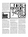
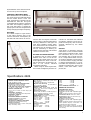
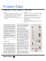
Product Data Multifunction Acoustic Calibrator — Type 4226 FEATURES: USES: 1/2″ ❍ Calibration and comprehensive check of and 4″ microphone set-ups and acoustic instruments conforming to IEC 651 and ANSI S 1.4-1983 such as sound level meters, dose meters, etc. 1/ ❍ Checks of filter sets and other frequency-dependent instruments ❍ Conforms to IEC 942 1988 and ANSI S 1.40 – 1984 ❍ Wide frequency range: tones from 31.5 Hz to 16 kHz in octave steps, plus tone at 12.5 kHz ❍ Calibration levels of 94 dB, 104 dB and 114 dB ❍ Free-field simulation for most 1/2″ Brüel & Kjær microphones ❍ Inverse A-weighting ❍ Recurrent pulses for time-weighting and crest factor checks The Multifunction Acoustic Calibrator Type 4226 enables you to check for the proper function of microphones, sound level meters and other related instruments. The 4226 generates accurate and stable signals with a frequency varying from 31.5 Hz to 16 kHz in octave steps, plus a signal at 12.5 kHz. The test signal can either be applied to a 1/2″ or 1/4″ microphone with the coupler provided, or picked up from an electrical output. For ease of use, the 4226 can simulate a constant free-field, and can apply a very accurate inverse A-weighting correction. All you have to do is check that the displayed and nominal values are identical within the given tolerances. An external generator can also be connected to the 4226 if a frequency sweep is desired. Introduction The high reliability of electronic measuring instruments such as sound level meters enables you to make accurate measurements after a simple check with a single-tone calibrator. In many cases this check is also carried out after each measurement to validate the results. To make sure an instrument is working correctly, more comprehensive checks are required periodically. You can make such a check and calibration with the Multifunction Acoustic Calibrator Type 4226 on microphones, Brüel & Kjær B 7/6-'89 K sound level meters and other acoustic instruments. The calibrator is easy to use so you can make comprehensive checks whenever extra confidence is required in a measurement. How the Calibrator Works Fig. 2 shows a block diagram of the 4226. A crystal-locked sine generator produces signals of very stable frequency. These signals pass through a variable gain amplifier and are sent to the transducers located in the 4226’s acoustic coupler. A reference microphone that is symmetrical to the microphone to be calibrated is situated in the coupler, both are exposed to the actual SPL in the coupling volume. The reference microphone drives a compression-loop, which in turn controls the variable gain amplifier of the calibrator. This method of signal generation has many advantages: over a wide frequency range it gives a very accurate and stable SPL. The SPL obtained depends essentially on the reference microphone which is itself very stable with respect to time and temperature variation. The SPL produced is practically independent of atmospheric pressure changes. The calibrator gives you a signal when the constant SPL in the coupler is correct. The response obtained from a microphone of any type, free-field or pressure, will always be its pressure response. However, the main interest for sound level meters is the free-field response. Because the difference between the pressure response and the free-field response is known for Brüel & Kjær microphones, you can correct the SPL in the coupler as a function of frequency to obtain a flat response from an ideal free-field microphone. This SPL correction is automatically applied by the calibrator when you specify which Brüel & Kjær microphone is to be calibrated. The construction of the calibrator also enables you to connect an external generator (for example, for frequency sweeps) or to pick up an electrical calibration signal (for example, for filter checks). 114 104 94 94 ,, Lin. Inv. A b Falcon Reference c Traditional Input Amp. + att. + A Weight Detector + Corrector Comparator Variable Gain Amplifier C o n t r o l l e r Sine Generator Function Level Uncal. Level Shift Zero Decector 1/2" Adaptor Microphone to calibrate AC Output SPL Set Up On Down Frequency Off Timer 892146/1e Reference Microphone cross section 880608e of the Calibrating the Sensitivity An SPL of 94 dB ±0.2 dB re 20 µPa at 1 kHz can be used for calibration purposes. You can use other calibration levels and frequencies with slightly reduced accuracy. See specifications. Checking the Frequency Response Type 4226 delivers a very stable tone with a frequency varying from 31.5 Hz to 16 kHz in octave steps, with an extra tone at 12.5 kHz. The 12.5 kHz tone is used for checking the highest frequency specified for Type 1 sound level meters. The actual frequency of the tone corresponds to those frequencies recommended in ISO 266. Checking A-weighting Networks A “94 dB inverse A-weighted” SPL can be applied in the acoustic coupler of the 4226. This means that an SPL of 94 dB, plus the corrections due to the microphone type and the sound field type, plus the inverse A-weighting correction is produced in the coupler. All the corrections are of course frequency-dependent, so to check an 2 Crest Fast Slow Test Cal. Error Dectector Cal. H.F. Transducer Fig.1 Simplified acoustic coupler Frequency Display Frequency L.F. Transducer Electronic Circuitry Ext. Gen. Sound Mic. Field a Press. Acoustic Coupler , , , SPL dB Fig.2 Simplified block diagram of the Multifunction Acoustic Calibrator Type 4226 A-weighted measuring instrument means making sure that it reads 94 dB within the tolerances. Note: at 31.5 Hz, the level in the coupler will reach 134 dB. Checking Input Attenuators With the 4226, there are three calibrated levels 94, 104 and 114 dB at all frequencies. You can use these three levels, for example, to check for the proper function of the input attenuators of an instrument, such as the 20 dB Input Attenuator ZF 0020 for Brüel & Kjær sound level meters or for calibration of a level recorder. Checking Time Weighting Networks This check is made by comparing the instrument readings for short pulses with the reading obtained for a continuous signal of the same level. The difference depends on the time weighting. The preset test frequency is 2 kHz (in accordance with IEC 651) however, whatever the frequency, each pulse is an integer number of cycles. The pulses are automatically repeated: one pulse of approximately 200 ms every 2 s for the F (Fast) time weighting and one pulse of approximately 500 ms every 8 s for the S (Slow) time weighting. The delay between pulses ensures that the detector of the instrument under test has time to decay before the next pulse. To check the time weighting, the feedback loop is disconnected since its response time is incompatible with this test. The pulses in this case are obtained by an intermittent 20 dB attenuation of the constant level set by a potentiometer. Checking Crest Factor Capabilities The signal used to check an instrument’s crest factor capability has the same RMS level as the constant test signal set on the calibrator. The check is made by comparing the readings with both signals, which should be identical within specified tolerances. The signal applied in the acoustic coupler has a crest factor of 3. To check the crest factor capability of sound level meters (standards require a crest factor capability of 10 for Type 0 and 1 instruments), the signal from the AC output socket (crest factor: 10) can be applied directly to the sound level meter input stage. It is valid to check a sound level meter in this way as the crest factor capability is normally limited by the detector of the sound level meter and not by the microphone. Calibrating a Noise Dose Meter Noise dose meters are calibrated using one of the three calibrated levels and the 4226’s built-in timer. The timer automatically switches off the stabilised SPL after 30 s. This gives a well-defined noise dose to calibrate the meter. The frequency response of the noise dose meter is checked by applying the inverse A-weighted level and by changing the signal frequency. AC Output This socket outputs a signal similar to the signal normally sent to the acoustic transducer. Consequently all the electrical tests which can be car- Fig.4 Type 4226 as delivered in its case ried out with this signal are similar to the acoustic tests described above. The only difference is the signal for crest factor capability checks which has a crest factor of 10. The electrical test signals are, for example, convenient for calibrating or checking recorders, filters and other instruments related to acoustic work. Fig.3 Checking and calibrating a sound level meter with Type 4226 Use with an External Generator A generator with an output voltage between 0.5 V and 1.5 V can be connected to this socket (see Fig. 2). The 4226 regulates the level in the coupler and ensures a constant SPL relative to the inverse reference microphone response. When using an external generator, the inverse A-weighting and the cor- rections for free-field and reference microphone response cannot be applied since they only refer to the frequencies delivered by the 4226's generator. General Type 4226 is a laboratory precision instrument. Its size, and the included power supply of 4 alkaline cells, make the instrument easy to use in-situ (for example, with a sound level meter or a large measurement set-up in an anechoic chamber). The simplicity of use also makes it highly portable; no specific documentation or correction tables are required for checks on standard Brüel & Kjær sound level meters, noise dose meters, microphones, etc. Specifications 4226 Calibration Function NOMINAL SOUND PRESSURE LEVELS: 94 dB, 104 dB and 114 dB REFERENCE SOUND PRESSURE LEVEL: (at Reference Ambient Conditions) 94 dB ± 0.2 dB re 20 µPa, at 1 kHz 10 dB AND 20 dB LEVEL STEP ACCURACY: ± 0.1 dB for f ≤ 8 kHz; ± 0.2 dB for f > 8 kHz NOMINAL FREQUENCIES: From 31.5 Hz to 16 kHz in octave steps, plus 12.5 kHz FREQUENCY ACCURACY: ± 1% re the ISO 266 stated exact frequencies FREQUENCY STABILITY: Better than ± 30 ppm REFERENCE AMBIENT CONDITIONS: Ambient Temperature: 20°C (68°F) Ambient Pressure: 1013 hPa INFLUENCE OF AMBIENT CONDITIONS: (at Reference Sound Pressure Level): Ambient Temperature: + 0.002 dB/°C in the range −10°C to +50°C (max. temp. uncertainty ±5°C*) Ambient Pressure: + 0.00055 dB/hPa in the range 650 hPa to 1080 hPa (max. press. uncertainty ±30 hPa*) * To satisfy IEC 942 Class 1 requirements Magnetic Field Sensitivity: No observable effect (<0.01 dB) at 100 A/m FREQUENCY RESPONSE: Pressure Field: Linear (94 dB, 104 dB and 114 dB SPL) and inverse A-weighting (94 dB SPL at 1 kHz) Equivalent 0°Free-field: Linear (94 dB, 104 dB and 114 dB SPL) and Inverse A-weighting (94 dB SPL at 1 kHz) LEVEL ACCURACY AT FIXED: FREQUENCIES (Lin. and inv. A-weighting): Pressure Field: (re 1 kHz): 31.5 Hz to 125 Hz : ±0.15 dB 250 Hz to 500 Hz : ±0.10 dB 2 kHz to 4 kHz : ±0.15 dB 8 kHz : ±0.25 dB 12.5 kHz to 16 kHz : ±0.5 dB Equivalent 0°Free-field: (re 1 kHz): 31.5 Hz to 125 Hz : ±0.2 dB 250 Hz to 500 Hz : ±0.10 dB 2 kHz 4 kHz 8 kHz 12.5k 16 kHz TOTAL HARMONIC : ±0.2 dB : ±0.3 dB : ±0.5 dB : ±1.0 dB : ±1.5 dB DISTORTION: ≤2% Additional Functions TIME WEIGHTING TESTS: Frequency: 2 kHz preselected Test Level: Typically 94 dB. Adjustable approx. ± 12 dB Signal: Continuous reference and tone burst Level Between Bursts: Ref. level − 20 dB Burst Duration: 500 ms (S) and 200 ms (F) CREST FACTOR TEST: Frequency: 2 kHz preselected Test Level: Typically 94 dB. Adjustable approx. ± 12 dB Signal: Continuous reference and tone burst of 40 Hz repetition frequency. Crest factor 3 at preselected and higher frequencies. Note: All burst signals consist of an integral number of sine waves with amplitude shifting at zero crossing 3 Specifications 4226 (continued) DOSE METER CALIBRATION: Calibration Period: 30 s Obtained Doses at 1 kHz: SPL dB IEC ANSI 94 0.26% ±0.01% 0.18% ±0.01% 104 2.62% ±0.20% 0.73% ±0.03% 114 26.20% ±1.90% 2.90% ±0.12% AC OUTPUT: Output Voltage: 12.5 mV ± 0.5 mV at settings 94 dB, 1 kHz and pressure mode. Voltage changes according to the selected level, type of microphone, sound field and function. Signal for testing time weighting and crest factor capabilities as above, except that the crest factor is 10 Note: The acoustic output is switched off when a plug is inserted in the AC OUT socket Output Impedance: 600 Ω, short-circuit proof Frequency Response: ± 0.2 dB from 31.5 Hz to 16 kHz in pressure mode EXTERNAL GENERATOR INPUT: Input Voltage: 0.5 V–1.5 V Input Impedance: 47 kΩ Frequency Response in the Coupler: 31.5 Hz to <8 kHz : ± 0.15 dB 8 kHz to <12.5 kHz : ± 0.25 dB 12.5 kHz to 16 kHz : ± 0.50 dB Note: These tolerances are relative to the inverse pressure response of the reference microphone (see User Manual). Only Pressure and Linear response are possible with external generator Standards EFFECTIVE COUPLER VOLUME: Approximately 400 cm 3 at 31.5 Hz, decreasing to approximately 30 cm3 at 1 kHz. Obtained by feedback SPECIFICATIONS VALID FOR BRÜEL & KJÆR MICROPHONE TYPES: Pressure Field: Type 4180 Equivalent 0° Free Field: “Microphone” setting Traditional Types Falcon Range Types “a” 4129, 4130, 4176 4187, 4188 “b” 4155, 4165 4189, 4190 “c” 4133, 4134, 4147, 4149 4191, 4192, 4193 For other types of microphones see manual Ambient Pressure: 650 hPa to 1080 hPa Dimensions and Weight (including mahogany case): Length: 265 mm (10.4 in) Width: 125 mm (4.9 in) Height: 62 mm (2.4 in) Weight: 1.5 kg (3.3 lb.) Note: All values are typical at 25 °C (77°F), unless measurement uncertainty is specified. All uncertainty values are specified at 2σ (i.e. expanded uncertainty using a coverage factor of 2) COMPLIANCE WITH STANDARDS: CE-mark indicates compliance with: EMC Directive. Safety EN 61010–1 and IEC 1010–1: Safety requirements for electrical equipment for measurement, control and laboratory use. EMC Emission EN 50081–1: Generic emission standard. Part 1: Residential, commercial and light industry. EN 50081–2: Generic emission standard. Part 2: Industrial environment. CISPR 22: Radio disturbance characteristics of information technology equipment. Class B Limits. FCC Rules, Part 15: Complies with the limits for a Class B digital device. EMC Immunity EN 50082–1: Generic immunity standard. Part 1: Residential, commercial and light industry. EN 50082–2: Generic immunity standard. Part 2: Industrial environment. Note 1: The specified calibration levels will not deviate more than 0.5 dB when exposed to RF specified in EN 50082–2 (10 V/m field). Temperature IEC 68–2–1 & IEC 68–2–2: Environmental Testing. Cold and Dry Heat. Operating Temperature: –10 to + 55°C (14 to 131°F) Storage Temperature: –25 to + 70°C (–13 to +158°F) Humidity IEC 68–2–3: Damp Heat: 90% RH (non-condensing at 30 °C (86°F)) Mechanical Non-operating: IEC 68–2–6: Vibration: 0.3 mm, 20 m/s2, 10–500 Hz IEC 68–2–27: Shock: 1000 m/s2 IEC 68–2–29: Bump: 3000 bumps at 250 m/s2 Enclosure IEC 529 (1989): Protection provided by enclosures: IP 20 The 4226 complies with: IEC 942 1988 Sound Calibrators, Class 1 (at Reference Sound Pressure Level) ANSI S1.40-1984, Specifications for Acoustical Calibrators General Specifications STABILISATION TIME: The LED corresponding to the selected frequency lights continuously when the SPL is stabilised (typically 2 to 10 s) BATTERIES: Type: 4 × 1.5 V alkaline cells IEC LR6 Life Time: 10 hours approx. at 20°C with alkaline batteries Battery Check: The “Batt. Low” LED is lit when reaching the last 10% of the battery life Environmental Ordering Information Type 4226 Includes the UA 1231: DP 0781: 2 × JP 0213: 4 × QB 0013: Multifunction Acoustic Calibrator following accessories: 1/2″ Microphone Adaptor 1/4″ Microphone Adaptor 2.5mm Mini Jack Plug Alkaline Batteries (IEC LR6) Optional Accessories DP 0682: DP 0750: AO 0481: Type 4003/4006 Adaptor (16 mm) Type 4004/4007 Adaptor (12 mm) Mini-Jack to BNC cable (1.2 m) Brüel&Kjær reserves the right to change specifications and accessories without notice Brüel & Kjær B 7/6-'89 K WORLD HEADQUARTERS: DK-2850 Nærum · Denmark · Telephone: +45 45 80 05 00 · Fax: +45 45 8014 05 · Internet: http://www.bk.dk · e-mail: [email protected] Australia (02) 9450-2066 · Austria 00 43-1-865 74 00 · Belgium 016/44 92 25 · Brazil (011) 246-8166 · Canada: (514) 695-8225 · China 10 68419 625 / 10 6843 7426 Czech Republic 02-67 02 11 00 · Finland (0)9-229 3021 · France (01) 69 90 69 00 · Germany 06103 / 908-5 · Hong Kong 2548 7486 · Hungary (1) 215 83 05 Italy (02) 57 60 4141 · Japan 03-3779-8671 · Republic of Korea (02) 3473-0605 · Nederland (0)30 6039994 · Norway 66 90 4410 · Poland (0-22) 40 93 92 Portugal (1) 471 14 53 Singapore (65) 275-8816 · Slovak Republic 07 378 9520 · Spain (91) 36810 00 · Sweden (08) 71127 30 · Switzerland 01/940 09 09 Taiwan (02) 713 9303 · United Kingdom and Ireland (0181) 954-2366 · USA 1 800 332 2040 Local representatives and service organisations worldwide BP 0772 – 16 97/07